


INSTRUCTIONS
IX71/IX51
INVERTED RESEARCH MICROSCOPE/ INVERTED BASIC MICROSCOPE
This instruction manual is for the Olympus Inverted Microscopes Models IX71 and IX51. To |
|
ensure the safety, obtain optimum performance and to familiarize yourself fully with the use |
|
of the microscope, we recommend that you study this manual thoroughly before operating |
|
the microscope. Retain this instruction manual in an easily accessible place near the work |
|
desk for future reference. |
A X 7 3 1 9 |

IX71/IX51
CONTENTS
Correct assembly and adjustments are critical for the microscope to exhibit its full performance. If you are going to assemble the microscope yourself, please read Chapter 9, “ASSEMBLY” (pages 55 to 65) carefully. For the modules provided with instruction manuals, also read the assembly procedures in their instruction manuals.
IMPORTANT — Be sure to read this section for safe use of the equipment. — |
1-4 |
|
|
|
|
|
|
|
1 |
MODULE NOMENCLATURE |
5 |
|
|
|
|
|
|
2 |
CONTROLS |
6-11 |
|
|
|
3TRANSMITTED LIGHT BRIGHTFIELD OBSERVATION PROCEDURE 12, 13
4 |
USING THE CONTROLS |
|
|
14-31 |
||
|
|
|
|
|||
|
4-1 |
Power Supply Unit and Microscope Frame......................................................................................... |
14-16 |
|||
|
|
1 |
Turning Power On, Adjusting the Brightness |
2 |
Light Path Selection |
|
|
|
3 |
Magnification Change (IX71 Only) |
4 |
Frame Clamping Plate |
|
|
|
5 |
Option Button (IX71 Only) |
|
|
|
|
4-2 |
Focusing Block............................................................................................................................................................................. |
|
|
16, 17 |
|
|
|
1 |
Rotation Direction of the Coarse/Fine Adjustment Knobs |
|
||
|
|
2 |
Adjusting the Coarse Adjustment Knob Tension |
|
||
|
|
3 |
Detaching the Fine Adjustment Knob |
4 |
Pre-focusing Lever |
|
|
4-3 |
Stage ........................................................................................................................................................................................................... |
|
|
18, 19 |
|
|
|
1 |
Placing the Specimen |
2 |
Moving the Specimen |
|
|
|
3 |
Connecting the Grounding Wire |
4 |
Adjusting the X-Axis/Y-Axis Knob Rotation Tension |
|
|
4-4 |
Observation Tube .................................................................................................................................................................... |
|
|
20-22 |
|
|
|
1 |
Adjusting the Interpupillary Distance |
2 |
Adjusting the Diopter |
|
|
|
3 |
Using the Eye Shades |
4 |
Using Eyepiece Micrometer Disks |
|
|
|
5 |
Selecting the Light Path of Observation Tube (U-TR30H-2 Only) |
|
||
|
|
6 |
Using the CT Turret (U-BI90CT Only) |
7 |
Adjusting the Tilt (U-TBI90 Only) |
|
|
4-5 |
Illumination Column IX2-ILL100........................................................................................................................... |
|
|
22-24 |
|
|
|
1 |
Tilting the Illumination Column |
2 |
Mounting the Filters |
|
|
|
3 |
Using the Field Iris Diaphragm |
|
|
|
|
|
4 |
Adjusting the Condenser Height Adjustment Knob Tension |
|
||
|
|
5 |
Mounting the Manipulator |
|
|
|
|
4-6 |
Illumination Column IX2-ILL30 ............................................................................................................................. |
|
|
25, 26 |
|
|
|
1 |
Using the Aperture Iris Diaphragm |
2 |
Removing the Condenser Lens |
|
|
|
3 |
Mounting the Filters |
4 |
Using the Filters |
|
|
4-7 |
Condenser .......................................................................................................................................................................................... |
|
|
27-29 |
|
|
|
1 |
Centering the Condenser |
2 |
Using the Aperture Iris Diaphragm |
|
|
|
3 |
Flipping Up the Condenser Holder |
|
|
|
|
4-8 |
Objectives .......................................................................................................................................................................................... |
|
|
30, 31 |
|
|
|
1 |
Oil-Proof Cap (UIS Series only) |
2 |
Adjusting the Correction Collar |
|
|
|
3 |
Using Immersion Objectives |
|
|
|

|
|
|
|
|
|
|
|
|
|
|
5 |
OTHER OBSERVATION METHODS |
32-43 |
|
|
|
|
|
|
|
|
5-1 |
Phase Contrast Observation (Using the IX2-ILL100 Column) ................................. |
32-35 |
|
|
5-2 |
Phase Contrast Observation (Using the IX2-ILL30 Column).................................... |
36, 37 |
|
|
5-3 Differential Interference Contrast Observation (Using the IX2-ILL100 Column) .... |
38-42 |
|
|
|
5-4 |
Simplified Polarized Light Observation (Using the IX2-ILL100 Column).............. |
43 |
|
|
5-5 |
Reflected Light Fluorescence Observation (See Separate Manual) ........................ |
43 |
|
|
|
|
|
|
6 |
PHOTOMICROGRAPHY AND TV OBSERVATION |
44-48 |
|
|
|
|
|
|
|
|
6-1 |
Photomicrography .................................................................................................................................................................. |
44-46 |
|
|
6-2 |
TV Observation ............................................................................................................................................................................ |
47, 48 |
|
|
|
|
|
|
7 |
TROUBLESHOOTING GUIDE |
49-51 |
|
|
|
|
|
|
|
|
|
|
|
|
8 |
SPECIFICATIONS |
52-54 |
|
|
|
|
|
|
9ASSEMBLY — See this section for the replacement of the light bulb. — 55-65
PROPER SELECTION OF THE POWER SUPPLY CORD ................................................................... |
66, 67 |
10 LAMP HOUSING INSPECTION SHEET |
68 |
This device complies with the requirements of directive 98/79/EC concerning in vitro diagnostic medical devices. CE marking means the conformity to the directive.
NOTE: This equipment has been tested and found to comply with the limits for a Class A digital device, pursuant to Part 15 of the FCC Rules. These limits are designed to provide reasonable protection against harmful interference when the equipment is operated in a commercial environment. This equipment generates, uses, and can radiate radio frequency energy and, if not installed and used in accordance with the instruction manual, may cause harmful interference to radio communications. Operation of this equipment in a residential area is likely to cause harmful interference in which case the user will be required to correct the interference at his own expense.
FCC WARNING: Changes or modifications not expressly approved by the party responsible for compliance could void the user’s authority to operate the equipment.
IX71/IX51
IMPORTANT
This microscope employs a UIS2/UIS (Universal Infinity System) optical design, and should be used with modules designed for the IX2 or BX2 series (as well as some of the modules designed for the Olympus IX or BX series).
For the applicable modules, please consult Olympus or the latest catalogues. Less than optimum performance may result if inappropriate module combinations are used.
If you want to use one or more motorized modules, you should prepare the IX2-UCB control box, U- HSTR2 hand switch, a PC and the IX2-BSW (Ver. 01.03) software (which runs on Windows 2000 or Windows Me).
Configuration of Instruction Manuals
Since these microscopes are expandable to a variety of systems, separate instruction manuals are prepared so that the user has to read only the manuals according to the user’s own system.
Manual Name |
Main Contents |
IX71/IX51 |
Observation procedures including transmitted light brightfield, |
|
phase contrast and DIC observations |
|
|
Fluorescence System for IX2 |
Reflected light fluorescence observation |
|
|
IX2-GCP |
Glass Center Plate |
|
|
IX2-MLWCD |
Mid-Long Working Distance Condenser |
|
|
IX2-DICD |
DIC Condenser |
|
|
U-FWT/FWR/FWO |
Motorized filter wheels (The U-FWT cannot be used with these |
|
microscopes.) |
|
|
IX2-UCB/U-HSTR2 |
Functions of the Control Box (incorporating the power supply) |
|
and Hand Switch |
|
|
IX2 Software for PC (CD-ROM) |
Methods of PC control of microscope functions |
IX2-BSW (Ver. 01.03 or later) |
|
|
|
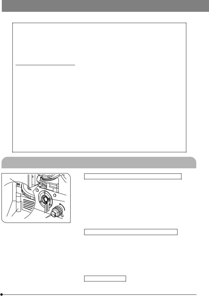
Precautions When Unpacking the Microscope
³ |
|
|
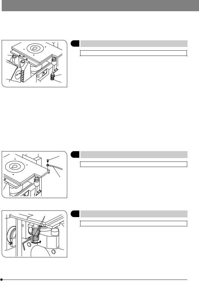
Releasing the Transport Lock of the Revolving Nosepiece |
|
|
|
|
#Never attempt to rotate the coarse or fine adjustment knob @ without |
|
|
|
|
|
removing the clamping rod. Otherwise, the focusing mechanism may |
|
|
|
|
be damaged. |
|
|
|
1. |
Loosen the screw ³ of the clamping rod ² using the Allen screwdriver |
|
|
| |
|
provided with the microscope frame. |
|
|
2. |
Rotate the coarse and fine adjustment knobs @ in the direction of the |
|
|
|
|
||
|
|
|
|
arrow and remove the clamping rod ². |
|
|
|
3. |
Attach the provided seal (10 mm dia., black) on the hole made after remov- |
² |
@ |
|
|
ing the transport lock knob to prevent penetration of dust through the hole. |
|
}Retain the clamping rod ² and screw ³ carefully because they will be |
|||
|
|
|
||
|
Fig. 1 |
|
|
used again the next time the microscope is transported. |
Releasing the Transport Lock of the Light Path Selector
#Never attempt to operate the light path selector without removing the transport lock knob |. Otherwise, the light path selector mechanism may be damaged.
·Rotate the knob counterclockwise to remove it.
·To prevent penetration of dust through the hole made after removing the transport lock knob, stop the hole by attaching the provided seal (10 mm
dia., black).
}Retain the knob carefully because it will be used again the next time the microscope is transported.
Stage (IX2-SFR, IX-MVR)
·Before transporting the stage, fix the flexible knobs with pieces of adhesive tape so that they will not move.
1
 SAFETY PRECAUTIONS
1.After the equipment has been used in an observation of a specimen that is accompanied with a potential of infection, clean the parts coming in contact with the specimen to prevent infection.
·Moving this product is accompanied with the risk of dropping the specimen. Be sure to remove the specimen before moving this product.
·In case the specimen is damaged by erroneous operation, promptly take the infection prevention measures.
2.The microscope is provided with a simplified waterproof mechanism. Therefore, if culture liquid or water is spilt on the stage, revolving nosepiece or microscope frame, damage to the equipment or an electrical shock may result. Immediately wipe the liquid or water off if it is spilt on them.
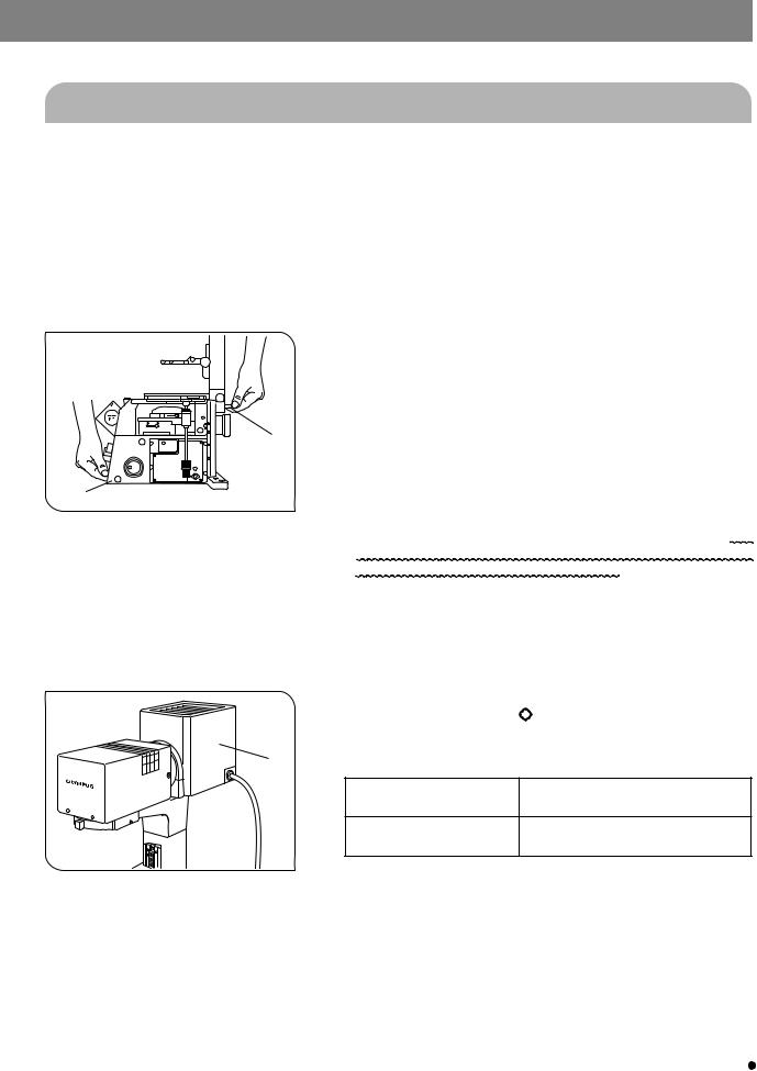
3.When moving the microscope, remove the observation tube, condenser
|
and reflected light mercury lamp housing, then carefully carry the micro- |
|
|
scope frame by the base (front edge) @ and the grasping part on the |
|
|
illumination column ² as shown in Fig. 2. (Weight: approx. 20 kg) |
|
|
Also be sure to remove the specimen since it may fall. |
|
|
When moving the microscope for a long distance, it is also recommended |
|
² |
to disconnect all cables from the equipment. |
|
|
When transporting it, also engage the transport lock mechanisms and |
|
|
package it sufficiently. |
|
@ |
Also be careful against slipping of hands during carrying. |
|
#Damage to the microscope will occur if you grasp it by other parts |
||
|
||
Fig. 2 |
including the stage, coarse/fine adjustment knobs, etc. |
|
|
4.The microscope is not covered by warranty in terms of laser safety. The user should assume liabilities for any consequence of user modification including introduction of the use of laser beam.
5.The surfaces of the lamp housing will become extremely hot during operation. When installing the microscope, make sure to allow ample free space (10 cm or more) around and in particular above the lamp housing.
6.When installing the microscope, route the power cord away from the lamp housing. Should the power cord come in contact with the hot lamp housing, the power cord could melt and cause electric shock.
IX2-ILL100 |
7. To avoid potential shock hazards and burns when replacing the light |
||
bulb, set the main switch to “ ” (OFF) then disconnect the power cord |
|||
|
|||
|
from the wall outlet in advance. Whenever you replace the bulb during |
||
³ |
use or right after use, allow the lamp housing ³ and bulb to cool before |
||
touching. (Fig. 3) |
|
||
|
Designated halogen bulb |
12V100WHAL (PHILIPS 7724) |
|
|
(Illumination column: IX2-ILL100) |
Bulb life: 2000 hours of rated operation |
|
|
Designated halogen bulb |
6V30WHAL (PHILIPS 5761) |
|
|
(Illumination column: IX2-ILL30) |
Bulb life: 100 hours of rated operation |
|
|
Fig. 3 |
8. Always use the power cord provided by Olympus. If no power cord is |
|
provided, please select the proper power cord by referring to the section |
|
|
|
|
|
|
“PROPER SELECTION OF THE POWER SUPPLY CORD” at the end of |
|
|
this instruction manual. If the proper power cord is not used, product |
|
|
safety performance cannot be warranted. |
|
|
9. Always ensure that the grounding terminal of the microscope and that of |
|
|
the wall outlet are properly connected. If the equipment is not grounded, |
|
|
Olympus can no longer warrant the electrical safety performance of the |
|
|
equipment. |
|
|
10. Never insert metallic objects into the air vents of the microscope frame |
2 |
|
as this could result in electrical shock, personal injury and equipment |
|
damage. |
|
|
|
|
|
|
IX71/IX51
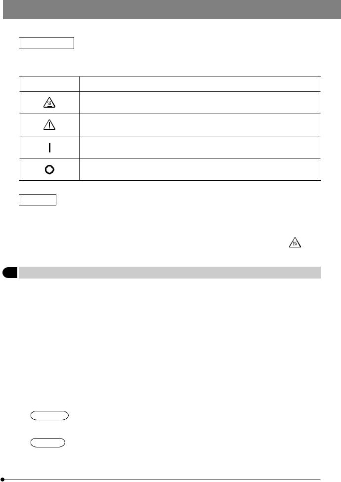
Safety Symbols
The following symbols are found on the microscope. Study the meaning of the symbols and always use the equipment in the safest possible manner.
Symbol |
Explanation |
|
|
Indicates that the surface becomes hot, and should not be touched with bare hands.
Before use, carefully read the instruction manual. Improper use could result in personal injury to the user and/or damage to the equipment.
Indicates that the main switch is ON.
Indicates that the main switch is OFF.
Warnings
Warning engravings are placed at parts where special precaution is required when handling and using the microscope. Always heed the warnings.
Warning engraving |
Lamp housing |
(High Temperature |
||
position |
(U-LH100L-3, U-LH100-3, IX-HLSH100, U-LS30-3) |
warning) |
|
|
|
||||
|
|
|
|
|
1Getting Ready
1.A microscope is a precision instrument. Handle it with care and avoid subjecting it to sudden or severe impact.
2.Do not use the microscope where it is subjected to direct sunlight, high temperature and humidity, dust or vibrations. (For operating conditions, see Chapter 8, “SPECIFICATIONS” on page 54).
3.An intermediate attachment with a thickness of up to 60 mm can be mounted between the microscope frame and binocular observation tube (U-BI90CT, U-BI90).
·If the U-TBI90 is used together with an intermediate attachment, the image may be cut off or obscured.
4.The oil-proof cap can only be mounted on a UIS Series 3 objective. Note that this does not change the optical performance. (For applicable objectives, see page 30.)
5.Restrictions in brightfield, phase contrast and DIC observations
·When the U-BI90CT is used together with the optional 2X magnification changer built into the microscope frame, the brightness in the peripheral area of the field may become insufficient.
(The insufficiency in brightness can be improved by extending the light path length using the U-EPA2 eye-point adjuster.)
·With the combination of U-TR30H + U-FWO, the full optical performance may not be able to be manifested with the objectives listed in @ below and it is not possible to use the objectives listed in ² below. (This also applies to objectives other than Series 3 objectives.)
UIS2 Series
1UPlanSApo4X, 10X2, UPlanFLN4X, 10X2, 20X, CPlanFLN10X, LUCPlanFLN20X, UPlanSApo100XO
2PlanN40X, PlanApoN60XO
UIS Series
@UPlanApo4X, 10X, UPlanFl4X, 10X and 20X, CPlanFl10X, LCPlanFl20X, UPlanApo100XOI3 ²Plan40X, UPlanApo40XOI3/340, PlanApo60XO3
3

6.Restrictions in TV observation
@The following combinations are not permitted in consideration of the optical performance.
·IX2-SPT + PE4X + U-PMTVC on the side port
·IX2-SPT + PE5X + U-PMTV1X on the side port (With the IX71, this is applicable only when the magnification changer is set to 1X.)
·U-TV0.35XC + 2X magnification changer (optional)
·U-TV0.35XC + DP50 (optional 2X magnification changer on the side port)
²The following combination may deteriorate the optical performance a little.
·U-TV0.35XC + DP50 (UPlanSApo/UPlanApo4X or 10X on the side port) (With the IX71, this is applicable only when the magnification changer is set to 1X.)
7.Restrictions in fluorescence observation
·With combination of IX2-SHA + U-FWR (x 2) + U-LH100HGAPO, objectives UPlanSApo/UPlanApo40X, UPlanFLN/ UPlanFl20X, UPlanFLN100XO/100XOI, UPlanFl100XO3, PlanAPoN60XO and PlanApo60XO3 cannot be used due to a problem in the optical performance. (This also applies to objectives other than Series 3 objectives.)
8.Other
·The U-TRU or U-TVCAC cannot be mounted on the side port.
·When a large module is attached to the U-TR30H straight photo tube, it will be difficult to confirm the specimen.
·Only either the lower back port or left side port can be used.
2Maintenance and Storage
1.To clean the lenses and other glass components, simply blow dirty away using a commercially available blower and wipe gently using a piece of cleaning paper (or clean gauze).
If a lens is stained with fingerprints or oil smudges, wipe it gauze slightly moistened with commercially available absolute alcohol.
 Since the absolute alcohol is highly flammable, it must be handled carefully.
Be sure to keep it away from open flames or potential sources of electrical sparks --- for example, electrical equipment that is being switched on or off.
Also remember to always use it only in a well-ventilated room.
2.Be sure to clean the oil immersion objective after use. Leaving immersion oil on it will degrades its performance.
3.Do not attempt to use organic solvents to clean the non-optical components of microscope. To clean them, use a lint-free, soft cloth slightly moistened with a diluted neutral detergent.
4.Never attempt to disassemble any part of the microscope.
5.When not using the microscope, make sure to set the main switch to “ ” (OFF), confirm that the lamp housing is cool enough and cover the microscope with the provided dust cover.
3Caution
If the microscope is used in a manner not specified by this manual, the safety of the user may be imperiled. In addition, the equipment may also be damaged. Always use the equipment as outlined in this instruction manual.
The following symbols are used to set off text in this instruction manual.
 : Indicates that failure to follow the instructions in the warning could result in bodily harm to the user and/or damage to equipment (including objects in the vicinity of the equipment).
# : Indicates that failure to follow the instructions could result in damage to equipment. } : Indicates commentary (for ease of operation and maintenance).
4Intended use
This instrument has been designed to be used to observe magnified images of specimens in routine and research applications.
Do not use this instrument for any purpose other than its intended use.
4
IX71/IX51
MODULE NOMENCLATURE
}The modules shown below are only the representative modules. As there are other modules which can be combined with the microscope but are not shown below, please also refer to the latest Olympus catalogues or your dealer.
For the modules marked *, refer to their separate instruction manuals.
Modules marked } are motorized modules, which should be used in combination with the IX2-UCB, a PC, etc.
Condenser
·IX2-LWUCDA2}
·IX2-LWUCD
·IX-ULWCD
·IX2-DICD*
·IX2-MLWCD*
·U-UCD8*
(Used together with IX-ADUCD)
Stage
·IX2-SFR
·IX-SVL2
· IX2-GS*
· IX2-SP
(Can be used together with IX-MVR)
· IX2-KSP
(Can be used together with CK40-MVR)
Eyepieces
· WHN10X · WHN10X-H
Observation Tube 
· U-BI90CT
· U-BI90
· U-TBI90
· U-TR30H-2
(Used together with IX-ATU)
· U-MO
6-Position Revolving
Nosepiece
(Fixed on the microscope frame)
Microscope Frame
· IX71S1F-3 · IX71S8F-3 · IX51S1F-3 · IX51S8F-3
Fluorescence Mirror Unit
Cassette
·IX2-RFACA*}
·IX2-RFAC*
Hand Switch
U-HSTR2*}
Transmitted Light Lamp Housing
·U-LH100L-3
·U-LH100-3 + U-RMT
·IX-HLSH100 + U-RMT
Transmitted Light Illumination Column
·IX2-ILL100
·IX2-ILL30
Reflected Light Fluorescence Illuminator
·IX2-RFA*
·IX2-RFAL*
Reflected Light High-Intensity
Lamp Housing
·U-LH100HG*
·U-LH100HGAPO*
·U-LH75XEAPO*
High-Intensity Power
Supply Unit
· U-RFL-T* · U-RX-T*
Control Box
IX2-UCB*}
Power Supply Unit
· TH4
· TL4
PC}
(IX2-BSW Ver. 01.03 or later software installed)
5

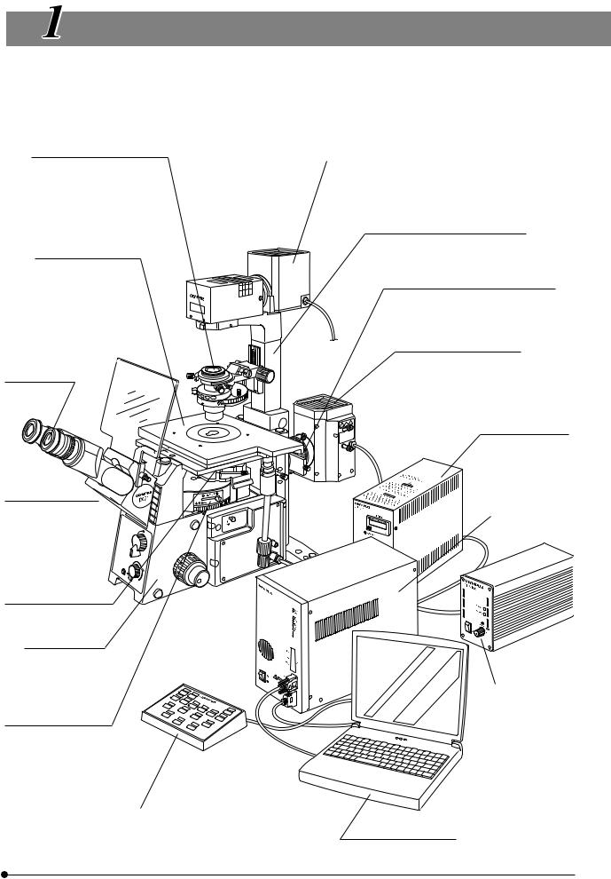
 CONTROLS
}If you have not yet assembled the microscope, read Chapter 9, “ASSEMBLY” (pages 55 to 65).
· The illustration shows the system composed of modules enclosed in |
|
. |
IX71
Filter pocket (Page 23)
Field iris diaphragm lever
Condenser centering knobs
Universal Condenser
IX2-LWUCD
Aperture iris diaphragm lever
Tilting Binocular
Tube
U-TBI90
Indicator plate pockets
Light path selector lever (Page 15)
 : Observation/
 : Side port
Option button (Page 16)
Transmitted light ON-OFF button (Page 14)
Light intensity control knob (Page 14)
Coarse adjustment knob tension adjustment ring (Page 16)
Coarse adjustment knob (Page 16)
Fine adjustment knob (Page 17)
Detachable.
X-axis knob (Page 19)
Y-axis knob (Page 19)
Magnification selector knob (Page 15)
Pushed in: 1X Pulled out: 1.6X
Halogen Lamp Housing
U-LH100L-3
Applicable halogen bulb: 12V100WHAL-L
Illumination Column
IX2-ILL100
Condenser height adjustment knob (Page 27)
Column tilt clamping screw (Page 22)
Stage center plate
Cross Stage
IX2-SFR
Option connector (Page 16)
Microscope
Frame
IX71S1F-3
IX71S8F-3
Power Supply Unit
TH4
Light intensity control knob (Page 14)
Main switch (Page 14)
6
IX71/IX51
IX51
Lamp Socket
U-LS30-3
Filter holder (Page 26)
Applicable halogen bulb: 6V30WHAL
Aperture iris diaphragm lever (Page 25)
Phase Contrast Slider 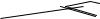


IX2-SL
Diopter adjustment ring (Page 20)
Binocular
Observation
Tube
U-BI90
Indicator plate pocket
Microscope Frame
IX51S1F-3
IX51S8F-3
Coarse adjustment knob tension adjustment ring (Page 16)
Coarse adjustment knob (Page 16)
Fine adjustment knob (Page 17)
Detachable.
Light path selector lever (Page 15)
 : Observation/
  : Side port
Illumination Column
IX2-ILL30
Plain Stage
IX2-KSP
Mechanical Stage
CK40-MVR
Y-axis knob (Page 19)
X-axis knob (Page 19)
Power Supply Unit
TL4
Main switch (Page 14)
Light intensity control knob (Page 14)
7
Left Side View of Microscope Frame
IX71
Allen screwdriver
storage position (Rear panel)
Side port 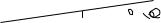

Transport lock knob
#Be sure to remove this before use.
IX51
Allen wrench and optical element centering knob (x 2)
storage position (Rear panel)
Eyepieces
WHN10X/WHN10X-H
Binocular Observation Tube
U-BI90CT
Diopter adjustment ring (Page 20)
Interpupillary distance adjustment scale (Page 20)
CT turret (Page 21)
Focus ring (Page 21)
Coarse adjustment knob (Page 16)
Pre-focusing lever (Page 17)
Fine adjustment knob (Page 17)
Detachable.
Allen wrench and optical element centering knob (x 2)
storage position (Rear panel)
Eyepieces
Allen screwdriver
WHN10X/WHN10X-H
storage position (Rear panel) Binocular Observation Tube U-BI90CT
Diopter adjustment ring (Page 20)
Interpupillary distance adjustment scale (Page 20)
CT turret (Page 21)
Focus ring (Page 21)
Side port
Coarse adjustment knob (Page 16)
Pre-focusing lever (Page 17)
Transport lock knob
#Be sure to remove this before use.
Fine adjustment knob (Page 17)
Detachable.
8

IX71/IX51
Other Modules
Monocular Tube
U-MO
Plain Stage
IX2-KSP
Plain Stage
IX2-SP
Cross Stage
IX-SVL2
Y-axis knob


10X eyepiece
(Fixed)
Manipulator mounting screw holes
M6 screws (x 6)
CK40-MVR/CK2-SS mounting screw holes
(On both sides)
Manipulator mounting screw holes
M6 screws (x 6)
IX-MVR/CK2-SS mounting screw holes
(On both sides)
Trinocular Observation Tube H
U-TR30H-2
Straight photo tube mount (Page 44)
Light path selector knob (Page 21)
Intermediate Tube
IX-ATU
Mechanical Stage |
}Can be mounted on the IX2-KSP. |
|
CK40-MVR |
||
|
Mechanical Stage |
}Can be mounted on the IX2-SP. |
|
IX-MVR |
||
|
Y-axis knob
X-axis knob 


X-axis knob
9
|
|
|
|
|
|
|
|
|
|
|
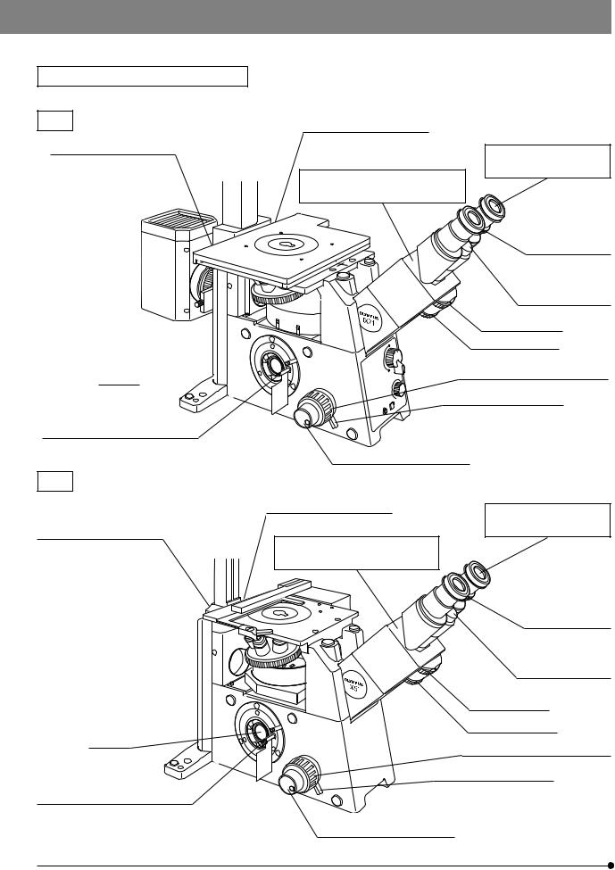
Long WD Universal Condenser |
|
UCD Adapter |
|
|
IX2-LWUCD |
|
IX-ADUCD |
|
|
|
|
|
|
}This is a manually controlled condenser.
Aperture iris |
Condenser height fine |
|
adjustment knob (Page 28) |
||
diaphragm lever |
||
|
||
(Page 27) |
Turret (Page 27) |
|
|
||
Index mounting holes |
|
|
|
Centering knob insertion holes |
|
|
(x 2) |
ULWCD Condenser
IX-ULWCD
}This is a manually controlled condenser.
Aperture iris |
Index mounting holes |
|
diaphragm lever |
(x 2) |
|
(Page 27) |
||
Turret (Page 27) |
||
|
Universal Condenser
U-UCD8
}This is a manually controlled condenser. Refer to the separate instruction manual for details.
Centering knob insertion hole
Motorized Long WD Universal Condenser
IX2-LWUCDA2
}This is a motorized condenser.
Index mounting holes
Centering knob insertion holes
Aperture iris diaphragm lever (Page 27)
10

IX71/IX51
Power Supply Unit
TH4
}The applicable halogen bulb is the 12V100WHAL-L. For details, refer to the separate instruction manual.
Hand Switch TH4-HS
}The IX71 does not need this module because its functions are incorporated in the microscope frame.
|
|
Light intensity control |
|
|
knob |
|
POWER LED |
|
Main switch |
REMOTE LED |
Lamp ON-OFF |
|
||
: ON. : OFF. |
|
switch |
|
Light intensity control knob |
|
Power Supply Unit |
}The applicable halogen bulb is the 6V30WHAL. |
|
TL4 |
||
|
||
|
|
Light intensity control knob |
Lamp socket |
|
connector |
Main switch
: ON. : OFF.
11

TRANSMITTED LIGHT BRIGHTFIELD
OBSERVATION PROCEDURE
}The following flow shows the operating procedure for the transmitted light brightfield observation which is the basic observation method of this microscope. The operating procedures for phase contrast observation and DIC observation will be described separately in Chapter 5, “OTHER OBSERVATION METHODS” on page 32.
For the fluorescence observation, refer to the separate instruction manual entitled “Manual/Motorized Reflected Fluorescence System”.
Set the main switch to “ I ” (ON).
Disengage the DIC slider and analyzer from the light path.
(Controls Used) |
(Page) |
@Main switch: “ I ” (ON) |
(P. 14) |
²Lamp ON-OFF button: ON |
(P. 14) |
³Light intensity control knob |
(P. 14) |
|
|
Disengage the filter other than the |
|Filter pocket |
(P. 23/26) |
|
|
|
frost filter from the light path. |
|||
|
|
|
|
||
|
|
|
|
|
|
|
|
|
|
|
|
Select the (observation) light path with the |
|
ƒLight path selector lever |
(P. 15) |
||
light path selector lever. |
|
||||
|
|
|
|||
|
|
|
|
…X-axis and Y-axis knobs |
(P. 19) |
|
|
|
|||
|
|
|
|
||
Place the specimen on the stage. |
|
||||
|
|
|
|
†Revolving nosepiece |
|
|
|
|
|
||
|
|
|
|
|
|
Engage a 10X objective in the light path. |
|
|
|||
|
|
|
|
|
|
|
|
|
|
|
|
|
|
|
|
|
|
Bring the specimen into focus. |
|
‡Coarse/fine adjustment knobs |
(P. 16) |
||
|
|
|
|
³Light intensity control knob |
(P. 14) |
|
|
|
|||
|
|
Adjust the brightness. |
|||
|
|
||||
|
|
|
|
ŠBinocular observation tube |
(P. 20) |
|
|
|
|
||
|
|
Adjust the interpupillary distance. |
‰Diopter adjustment ring |
(P. 20) |
|
|
|
Adjust the diopter. |
‹Condenser height adjustment knob* (P. 27/ |
||
|
|
||||
|
|
Adjust the light axis. |
28) |
|
|
|
|
|
|
ŒCondenser centering knobs* |
(P. 27/28) |
|
|
|
|
||
|
|
|
|
™Field iris diaphragm lever* |
(P. 24) |
|
|
|
|
||
Engage the objective to be used in the light |
|
†Revolving nosepiece |
|
||
path and bring the specimen in focus. |
|
‡Coarse/fine adjustment knobs |
(P. 16) |
||
|
|
|
|
šAperture iris diaphragm lever |
(P. 29) |
|
|
|
|
||
|
|
|
|
||
Adjust the aperture iris and field iris diaphragms. |
|
||||
|
™Field iris diaphragm lever* |
(P. 24) |
|||
|
|
|
|
||
|
|
Engage the required filters. |
|Filter pocket |
(P. 23/26) |
|
|
|
||||
|
|
Adjust the brightness. |
³Light intensity control knob |
(P. 14) |
|
|
|
||||
|
|
|
|
|
|
Start observation. |
|
|
|||
* This operation is not required when the IX2-ILL30 illumination column is used.
12

IX71/IX51
|
™
Œ
š
‰
Š
ƒ
With the IX71
³
²
‡ |
Hand Switch |
TH4-HS |
³
²
‹
†
ƒ
With the IX51
…
Power Supply Unit
TH4
@
³
When the TL4 power supply unit is used
³
@
} Make a photocopy of the observation procedure pages and post it near your microscope.
13
 USING THE CONTROLS
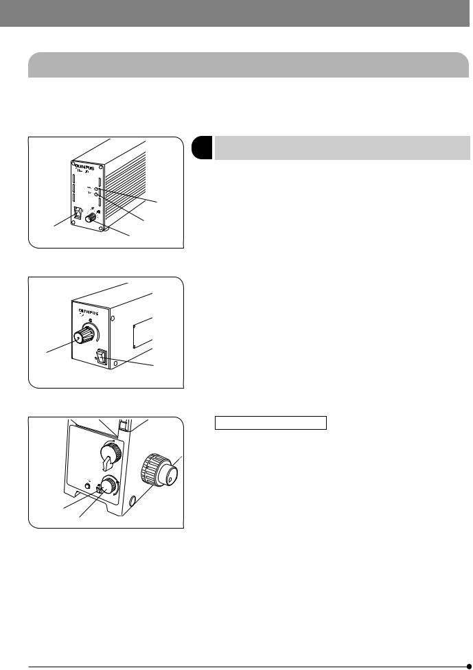
4-1 Power Supply Unit and Microscope Frame
}The power supply unit to be used is variable depending on the illumination column in use.
·IX2-ILL100: TH4 power supply unit.
·IX2-ILL30: TL4 power supply unit.
|
1 |
Turning Power On, Adjusting the |
(Figs. 4 & 5) |
|||
|
Brightness |
|
||||
|
|
|
||||
|
|
1. |
Make sure that the light intensity control knob @ is in the MIN (minimum |
|||
|
|
|
intensity) position and set the main switch ² to “ I ” (ON). (The POWER |
|||
|
³ |
|
LED ³ lights up.) |
|
|
|
|
2. |
Rotate the knob @ toward MAX (maximum intensity) to increase the |
||||
|
| |
|
intensity and the illumination brightness. |
|
|
|
² |
}With the TH4, the position (approx. 9 V) marked indicates the position |
|||||
@ |
||||||
|
|
where the daylight illumination suitable for photomicrography is obtained |
||||
|
Fig. 4 |
|
when the 45LBD filter is engaged in the light path. |
|
||
|
|
The position marked of the IX71 and TH4-HS also has the identical |
||||
|
|
|
||||
|
|
|
function. |
|
|
|
|
|
|
With the TL4, the position marked |
is not provided and even |
||
|
|
|
the maximum light intensity (6 V) may sometimes be unsuitable |
|||
|
|
|
for photomicrography. |
|
|
|
@
²
Fig. 5
…
ƒ
Fig. 6
With the IX71 Frame (Fig. 6)
}If the TH4 connection cable provided with the microscope frame is connected to the TH4 (the REMOTE LED | lights in this case), the light intensity control knob @ on the power supply unit is defeated and only the light intensity control knob ƒ on the front of the microscope frame is available.
1.Press the transmitted light ON-OFF button … (so that the button is illuminated) and adjust the brightness with the light intensity control knob ƒ.
2.To turn the lamp OFF, set the transmitted light ON-OFF button … to OFF.
#The microscope frame is in standby mode when the REMOTE LED | is lit. Power of about 2.5 W is consumed in this period.
When the microscope system is not be used for a long period, set the main switch ² to “ ” (OFF).
14
IX71/IX51
When the TH4-HS Hand Switch is Used (Fig. 7)
ƒ
}The illumination brightness can be adjusted from the hand switch in the same way as on the IX71 microscope frame.
The hand switch is provided with double-sided adhesive tape, so it can be adhered to an easy-to-use position.
…
Fig. 7
IX71
@
²
Fig. 8
2 |
Light Path Selection |
(Figs. 8 & 9) |
}The light path selector lever allows for light path switching between the |
||
|
observation ( ) and side port ( |
) paths. |
: Observation 100% light path.
 : Side port 100% light path (with the IX71S1F-2/IX51S1F-2 frame) Side port light path 80%/Observation 20% light path (with the IX71S8F-2/IX51S8F-2)
}The light path to the lower back port can also be set by the manufacturer’s part replacement operation. (IX2-LBPC)
IX51 
@
Fig. 9
IX71 |
|
3 Magnification Change (IX71 Only) |
(Fig. 10) |
|
|
When the magnification selector knob @ is pulled out, the magnification |
|
|
|
will be 1.6X. When the knob is pushed in, the magnification will be 1X. |
|
|
|
}The 1X 1.6X magnification changer lens can be replaced with a 1X 2X |
|
|
@ |
magnification changer lens (IX2-CA2) by the manufacturer operation. |
|
|
|
|
|
Fig. 10
15
4Frame Clamping Plate
}This is the module for clamping the microscope frame onto an anti-vibration platform. The applicable anti-vibration platforms are the following four models
·25 mm pitch and 50 mm pitch anti-vibration platforms.
·1-inch pitch and 2-inch pitch anti-vibration platforms. For the assembly procedure, see item 10 on page 65.
5 |
Option Button (IX71 Only) |
(Fig. 8) |
}Pressing the option button ² makes it possible to release or close an external shutter (UNIBLITZ, etc.) To do this, the external shutter be connected to the right side of the frame using a commercially available BNC cable.
#When the option button is not used, leave the cap attached to it.
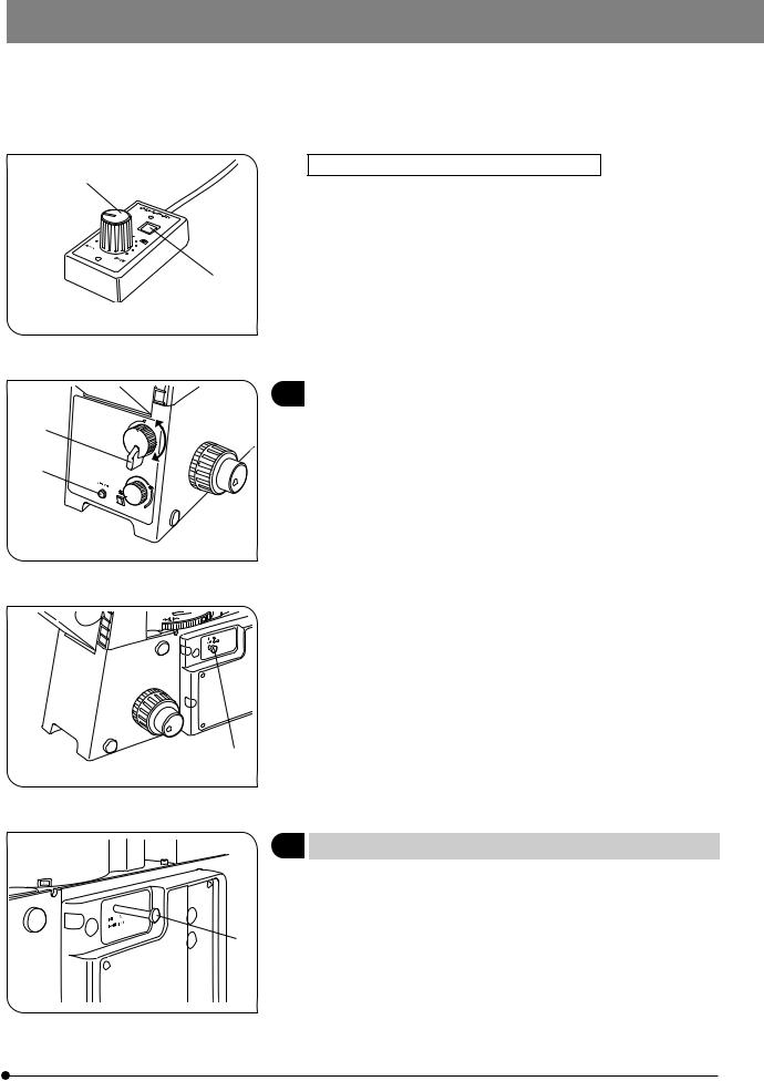
4-2 Focusing Block
²
@³
1 |
Rotation Direction of the Coarse/ |
(Fig. 11) |
|
Fine Adjustment Knobs |
|||
|
}Rotating the coarse or fine focus adjustment knob @ toward the front (in the direction of the arrow) raises the objective and toward the rear (opposite direction) lowers the objective.
2 |
Adjusting the Coarse Adjustment Knob |
(Fig. 11) |
|
Tension |
|||
|
Fig. 11
#Always use the rotation tension adjustment ring ² to control the rotation tension of the coarse adjustment knob.
The tension of the coarse adjustment knob has been pre-adjusted to optimum tension, but this can be changed as required. Turn the rotation tension adjustment ring ² in the direction of the arrow to decrease the knob’s tension and in the opposite direction to increase it.
If the objective lowers by its own weight or the focusing obtained with the fine adjustment knob is lost soon, the tension is set too low. In this case, turn the rotation tension adjustment ring in the opposite direction to the arrow to increase the tension.
16
IX71/IX51
|
|
|
|
3 |
|
|
|
Detaching the Fine Adjustment Knob |
(Fig. 11) |
|
}The fine adjustment knob is designed detachable in order to prevent interference between the knob and the operator’s hand manipulating the X- and Y-axis knobs.
·Loosen the clamping screw ³ using the Allen screwdriver and remove the fine adjustment knob.
After detaching, the seat of the fine adjustment knob is hollowed to facilitate manipulation with the thick of a finger.
4 |
Pre-focusing Lever |
(Fig. 12) |
|
|
}The pre-focusing lever prevents collision between the specimen and |
||
|
objective and simplifies the focusing operation. |
|
|
|
After bringing the specimen into approximate focus with the coarse |
||
|
adjustment knob, turn the pre-focusing lever @ in the direction of the |
||
|
arrow to lock it. Hereafter, the upper limit of the coarse adjustment will |
||
|
be limited at the position where the lever is locked. |
|
|
@ |
When bringing a specimen in focus, approximate focus can be obtained |
||
by simply raising the coarse adjustment to the stop position so all you |
|||
|
|||
Fig. 12 |
have to do more is control the fine adjustment knob. |
|
|
|
}The stage up/down movement using the fine adjustment knob is not |
||
|
limited. |
|
|
|
#When the pre-focusing lever is locked, the coarse adjustment stroke is |
||
limited by the mechanism and it cannot reach the previous lower limit. If you want to control the coarse adjustment knob to the previous lower limit, unlock the pre-focusing lever.
17

4-3 Stage
@ |
1 Placing the Specimen |
(Figs. 13 to 16)
With the IX2-SFR or IX-SVL2 Stage |
(Fig. 13) |
|
|
Place the specimen on the center of the stage.
}In the case of a slide glass specimen, place the specimen with the cover glass facing down.
}If the specimen is prone to slide on the stage, attach the stage clips (IX-SCL) @ and clamp the specimen down with the clips.
Fig. 13
@
Fig. 14
With the IX-MVR Mechanical Stage + IX2-SP Stage (Figs. 14 & 15)
}96-well or 24-well microtiter plates, etc. are held in place by the specimen holder.
Microtiter plates with dimensions of max. 136 mm x 92 mm can be accommodated in this way.
1.Open the spring-loaded finger of the specimen holder @ and slide the microtiter plate into the holder frame. Gently release the curved finger to clamp. (Fig. 14)
|
}To secure other vessels than microtiter plates, various optional holders |
|||
² |
|
are available. A Terasaki plate holder ² is available for holding Terasaki |
||
³ |
|
plates (72-well, or 60-well). When using this, it is necessary to replace the |
||
|
stage scales with those provided with the plate holder. Petri dish holder |
|||
| |
|
|||
|
³ is available for 35 mm, 54 mm and 65 mm diameter petri dishes, and |
|||
|
|
a slide glass holder | is available for holding slide glass, and the IX2- |
||
|
|
BCTP* ƒ is available for a blood cell test plate holder. (Fig. 15) |
|
|
|
* A blood cell test plate or other calculating chamber for bacteria and |
|||
|
|
|
+0.3 |
|
ƒ |
|
eosinophil with mounting section dimensions corresponding to H 77+0 x |
||
|
+0.3 |
|
||
|
|
V 35+0 x D 2 mm can be used. A 60 mm diameter petri dish can also be |
||
Fig. 15 |
|
used. |
|
|
|
|
|
||
|
|
|
||
|
With the CK40-MVR Mechanical Stage + IX2-KSP Stage |
(Fig. 16) |
||
|
1. |
96-well or 24-well microtiter plates can be held directly in place by |
||
@ |
|
widening the specimen holder @. |
|
|
2. |
To secure other vessels than microtiter plates, use one of the following |
|||
² |
||||
|
|
holders provided with the mechanical stage. |
|
|
³ |
|
· Terasaki plate holder ² (AB4488): For test plate, 35 mm diameter petri |
||
|
|
dish holder | or 65 mm diameter petri dish |
|
|
| |
|
· Slide glass holder ³ (AB4489): For slide glass or 54 mm petri dish |
||
}The IX2-BCTP blood cell test plate holder (Fig. 15 ƒ) can also be used. |
||||
Fig. 16
18
IX71/IX51
|
2 Moving the Specimen |
(Fig. 17) |
³ |
With the IX2-SFR or IX-SVL2 Stage |
|
|
|
To move the specimen to a desired position, rotate the X-axis knob @ and Y-axis knob ².
}When the index mark on the upper stage is aligned with the index line ³ ² provided on the substages, the center of the stage center plate aperture is almost in the center of the optical axis. Use this as a guideline when
@ |
moving the specimen. |
|
Fig. 17 |
The travel area is 50 mm (X-axis) x 50 mm (Y-axis). |
|
}If, after observing a specimen with an objective with short WD (0.5 mm |
||
|
||
|
or less), the revolving nosepiece is rotated to change the objective, the |
|
|
objective may interfere with the center plate. When using objectives |
|
|
with short WD or immersion objectives frequently by avoiding interference, |
|
|
it is recommended to attach the optional IX-CP50 center plate with a |
|
|
center aperture diameter of 50 mm. |
|
|
}The travel area of the IX-SVL2 stage is 50 mm (X-axis) x 43 mm (Y-axis). |
|
|
|
|
|
With the IX-MVR or CK40-MVR Mechanical Stage |
|
|
|
|
|
Specimens are moved in the same manner as outlined above. |
|
|
}The stage travel area is 130 mm (X-axis) x 85 mm (Y-axis) with the IX-MVR |
|
|
or 120 mm (X-axis) x 78 mm (Y-axis) with the CK40-MVR. |
² |
3 |
Connecting the Grounding Wire |
(Fig. 18) |
|
|
|
With the IX2-SFR or IX-SVL2 Stage |
|
|
|
|
}A grounding wire can be attached to the stage for electrophysiological |
||
@ |
|
|
experiments, etc. |
|
|
|
Prepare a grounding wire @ and one M4 screw ² and attach the |
||
|
|
|
grounding wire as shown in Fig. 18. |
|
|
|
#The screw hole may sometimes be stuck by paint, etc. In such a |
||
|
|
|
case, screw in the M4 screw a few times to expose the metallic |
|
Fig. 18 |
|
|
thread inside the screw hole and improve the contact before |
|
|
|
attaching the grounding wire firmly. |
|
|
|
|
|
|
|
@ |
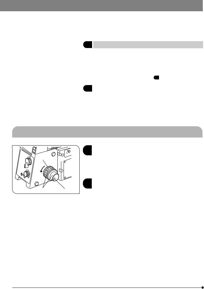
4 |
Adjusting the X-Axis/Y-Axis Knob Rotation Tension |
(Fig. 19) |
|
|
|
With the IX-SVL2 Stage |
|
|
|
|
}The tension of the X-axis and Y-axis knobs can be adjusted independently. |
||
|
|
1. |
Loosen the two setscrews @ of a knob using the provided Allen wrench, |
|
|
|
|
hold the stage so that it will not move, then rotate the knob to adjust the |
|
|
|
|
tension. Rotating it in the direction of the arrow increases the tension and |
|
|
|
|
rotating in the opposite direction decreases the tension. |
|
|
|
2. |
After adjustment, tighten the setscrews firmly. |
|
Fig. 19 |
|
#If the tension of a knob is too tight or too loose, skipping or returning |
||
|
|
of image may occur during the stage movement. |
|
|
|
|
|
|
|
19
 Loading...