


LM120K-15-883
NSC LM120K-15-883, LM120K-12-883, LM120HG-5MW8, LM120HG-15MW8, LM120H-5.0-883 Datasheet
...
TL/H/7767
LM120/LM320 Series 3-Terminal Negative Regulators
November 1994
LM120/LM320
Series 3-Terminal Negative Regulators
General Description
The LM120 series are three-terminal negative regulators
with a fixed output voltage of
b
5V,
b
12V, and
b
15V, and
up to 1.5A load current capability. Where other voltages are
required, the LM137 and LM137HV series provide an output
voltage range of
b
1.2V to
b
47V.
The LM120 need only one external componentÐa compen-
sation capacitor at the output, making them easy to apply.
Worst case guarantees on output voltage deviation due to
any combination of line, load or temperature variation as-
sure satisfactory system operation.
Exceptional effort has been made to make the LM120 Se-
ries immune to overload conditions. The regulators have
current limiting which is independent of temperature, com-
bined with thermal overload protection. Internal current limit-
ing protects against momentary faults while thermal shut-
down prevents junction temperatures from exceeding safe
limits during prolonged overloads.
Although primarily intended for fixed output voltage applica-
tions, the LM120 Series may be programmed for higher out-
put voltages with a simple resistive divider. The low quies-
cent drain current of the devices allows this technique to be
used with good regulation.
Features
Y
Preset output voltage error less than
g
3%
Y
Preset current limit
Y
Internal thermal shutdown
Y
Operates with input-output voltage differential down to
1V
Y
Excellent ripple rejection
Y
Low temperature drift
Y
Easily adjustable to higher output voltage
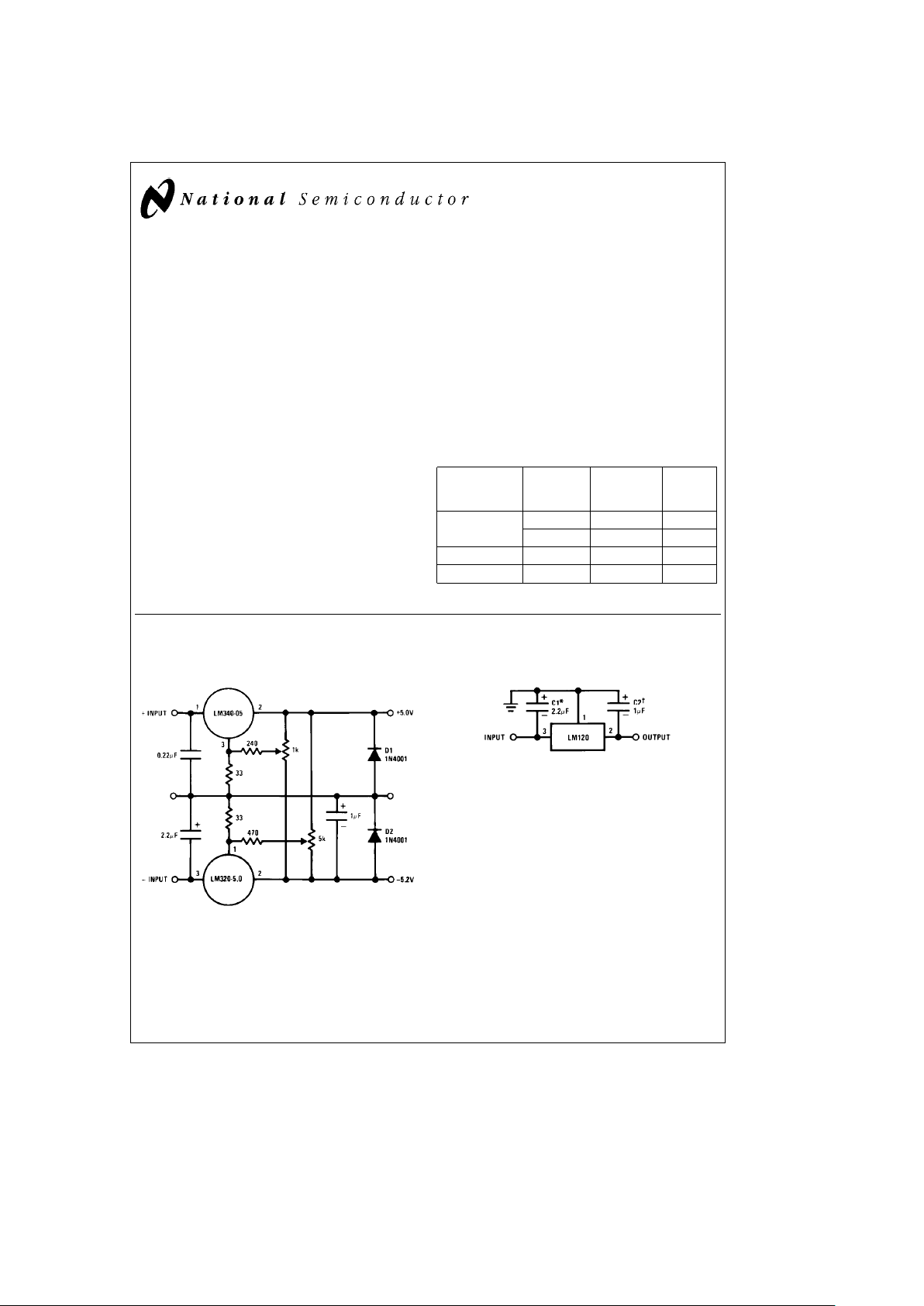
LM120 Series Packages and Power Capability
Rated Design
Device Package Power Load
Dissipation Current
LM120/LM320 TO-3 (K) 20W 1.5A
TO-39 (H) 2W 0.5A
LM320 TO-220 (T) 15W 1.5A
LM320M TO-202 (P) 7.5W 0.5A
Typical Applications
Dual Trimmed Supply
TL/H/7767– 3
Fixed Regulator
TL/H/7767– 2
*Required if regulator is separated from filter capacitor by more than 3
×
. For
value given, capacitor must be solid tantalum. 25 mF aluminum electrolytic
may be substituted.
²
Required for stability. For value given, capacitor must be solid tantalum. 25
mF aluminum electrolytic may substituted. Values given may be increased
without limit.
For output capacitance in excess of 100 mF, a high current diode from
input to output (1N4001, etc.) will protect the regulator from momentary
input shorts.
C
1995 National Semiconductor Corporation RRD-B30M115/Printed in U. S. A.
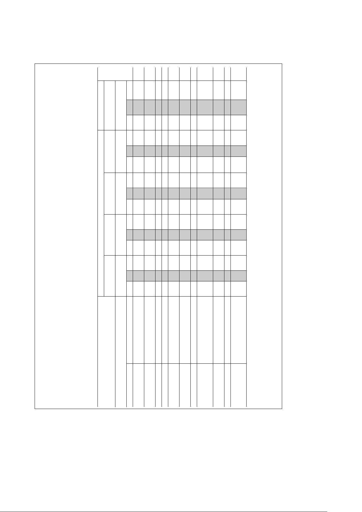
b
5 Volt Regulators (Note 3)
Absolute Maximum Ratings
If Military/Aerospace specified devices are required, Input-Output Voltage Differential 25V
please contact the National Semiconductor Sales
Junction Temperatures See Note 1
Office/Distributors for availability and specifications.
Storage Temperature Range
b
65
§
Cto
a
150
§
C
(Note 5)
Lead Temperature (Soldering, 10 sec.) 300
§
C
Power Dissipation Internally Limited
Plastic 260
§
C
Input Voltage
b
25V
Electrical Characteristics
Metal Can Package Power Plastic Package
Order Numbers
LM120K-5.0 LM320K-5.0 LM120H-5.0 LM320H-5.0 LM320T-5.0
(TO-3) (TO-3) (TO-39) (TO-39) (TO-220)
Units
Design Output Current (I
D
) 1.5A 1.5A 0.5A 0.5A 1.5A
Device Dissipation (P
D
) 20W 20W 2W 2W 15W
Parameter Conditions (Note 1) Min Typ Max Min Typ Max Min Typ Max Min Typ Max Min Typ Max
Output Voltage T
J
e
25
§
C, V
IN
e
10V,
b
5.1
b
5
b
4.9
b
5.2
b
5
b
4.8
b
5.1
b
5
b
4.9
b
5.2
b
5
b
4.8
b
5.2
b
5
b
4.8 V
I
LOAD
e
5mA
Line Regulation T
J
e
25
§
C, I
LOAD
e
5 mA,
10 25 10 40 10 25 10 40 10 40 mV
V
MIN
s
V
IN
s
V
MAX
Input Voltage
b
25
b
7
b
25
b
7
b
25
b
7
bb
25
b
7
b
25
b
7.5 V
Ripple Rejection f
e
120 Hz 54 64 54 64 54 64 54 64 54 64 dB
Load Regulation, T
J
e
25
§
C, V
IN
e
10V,
50 75 60 100 30 50 30 50 50 100 mV
(Note 2) 5 mA
s
I
LOAD
s
I
D
Output Voltage,
b
7.5V
s
V
IN
s
V
MAX
,
b
5.20
b
4.80
b
5.25
b
4.75
b
5.20
b
4.80
b
5.25
b
4.75
b
5.25
b
4.75 V
(Note 1) 5 mA
s
I
LOAD
s
I
D
,P
s
P
D
Quiescent Current V
MIN
s
V
IN
s
V
MAX
12 12 12 12 1 mA
Quiescent Current T
J
e
25
§
C
Change V
MIN
s
V
IN
s
V
MAX
0.1 0.4 0.1 0.4 0.05 0.4 0.05 0.4 0.1 0.4 mA
5mA
s
I
LOAD
s
I
D
0.1 0.4 0.1 0.4 0.04 0.4 0.04 0.4 0.1 0.4 mA
Output Noise Voltage T
A
e
25
§
C, C
L
e
1 mF, I
L
e
5 mA,
150 150 150 150 150 mV
V
IN
e
10V, 10 Hz
s
f
s
100 kHz
Long Term Stability 5 50 5 50 5 50 5 50 10 mV
Thermal Resistance
Junction to Case 3 3 Note 4 Note 4 4
§
C/W
Junction to Ambient 35 35 Note 4 Note 4 50
§
C/W
Note 1: This specification applies over
b
55
§
C
s
T
J
s
a
150
§
C for the LM120 and 0
§
C
s
T
J
s
a
125
§
C for the LM320.
Note 2: Regulation is measured at constant junction temperature. Changes in output voltage due to heating effects must be taken into account separately. To ensure constant junction temperature, low duty cycle, pulse testing is
used. The LM120/LM320 series does have low thermal feedback, improving line and load regulation. On all other tests, even though power dissipation is internally limited, electrical specifications apply only up to P
D
.
Note 3: For
b
5V 3 amp regulators, see LM145 data sheet.
Note 4: Thermal resistance of typically 85
§
C/W (in 400 linear feet air flow), 224
§
C/W (in static air) junction to ambient, of typically 21
§
C/W junction to case.
Note 5: Refer to RETS120-5H drawing for LM120H-5.0 or RETS120-5K drawing for LM120-5K military specifications.
2
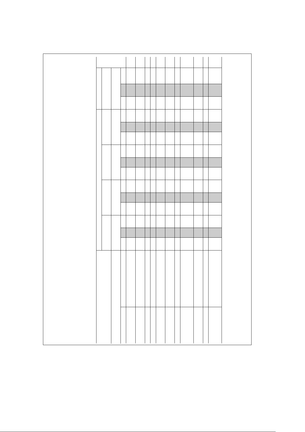
b
12 Volt Regulators
Absolute Maximum Ratings
If Military/Aerospace specified devices are required, Input-Output Voltage Differential 30V
please contact the National Semiconductor Sales
Junction Temperatures See Note 1
Office/Distributors for availability and specifications.
Storage Temperature Range
b
65
§
Cto
a
150
§
C
(Note 4)
Lead Temperature (Soldering, 10 sec.) 300
§
C
Power Dissipation Internally Limited
Input Voltage
b
35V
Electrical Characteristics
Metal Can Package Power Plastic Package
Order Numbers
LM120K-12 LM320K-12 LM120H-12 LM320H-12 LM320T-12
(TO-3) (TO-3) (TO-39) (TO-39) (TO-220)
Units
Design Output Current (I
D
) 1A 1A 0.2A 0.2A 1A
Device Dissipation (P
D
) 20W 20W 2W 2W 15W
Parameter Conditions (Note 1) Min Typ Max Min Typ Max Min Typ Max Min Typ Max Min Typ Max
Output Voltage T
J
e
25
§
C, V
IN
e
17V,
b
12.3
b
12
b
11.7
b
12.4
b
12
b
11.6
b
12.3
b
12
b
11.7
b
12.4
b
12
b
11.6
b
12.4
b
12
b
11.6 V
I
LOAD
e
5mA
Line Regulation T
J
e
25
§
C, I
LOAD
e
5 mA,
4 10 4 20 4 10 4 20 4 20 mV
V
MIN
s
V
IN
s
V
MAX
Input Voltage
b
32
b
14
b
32
b
14
b
32
b
14
b
32
b
14
b
32
b
14.5 V
Ripple Rejection f
e
120 Hz 56 80 56 80 56 80 56 80 56 80 dB
Load Regulation, T
J
e
25
§
C, V
IN
e
17V,
30 80 30 80 10 25 10 40 30 80 mV
(Note 2) 5 mA
s
I
LOAD
s
I
D
Output Voltage, 14.5V
s
V
IN
s
V
MAX
,
b
12.5
b
11.5
b
12.6
b
11.4
b
12.5
b
11.5
b
12.6
b
11.4
b
12.6
b
11.4 V
(Note 1) 5 mA
s
I
LOAD
s
I
D
,P
s
P
D
Quiescent Current V
MIN
s
V
IN
s
V
MAX
24 24 24 24 2 4 mA
Quiescent Current T
J
e
25
§
C
Change V
MIN
s
V
IN
s
V
MAX
0.1 0.4 0.1 0.4 0.05 0.4 0.05 0.4 0.1 0.4 mA
5mA
s
I
LOAD
s
I
D
0.1 0.4 0.1 0.4 0.03 0.4 0.03 0.4 0.1 0.4 mA
Output Noise Voltage T
A
e
25
§
C, C
L
e
1 mF, I
L
e
5 mA,
400 400 400 400 400 mV
V
IN
e
17V, 10 Hz
s
f
s
100 kHz
Long Term Stability 12 120 12 120 12 120 12 120 24 mV
Thermal Resistance
Junction to Case 3 3 Note 3 Note 3 4
§
C/W
Junction to Ambient 35 35 Note 3 Note 3 50
§
C/W
Note 1: This specification applies over
b
55
§
C
s
T
J
s
a
150
§
C for the LM120 and 0
§
C
s
T
J
s
a
125
§
C for the LM320.
Note 2: Regulation is measured at constant junction temperature. Changes in output voltage due to heating effects must be taken into account separately. To ensure constant junction temperature, low duty cycle, pulse testing is
used. The LM120/LM320 series does have low thermal feedback, improving line and load regulation. On all other tests, even though power dissipation is internally limited, electrical specifications apply only up to P
D
.
Note 3: Thermal resistance of typically 85
§
C/W (in 400 linear feet/min air flow), 224
§
C/W (in static air) junction to ambient, of typically 21
§
C/W junction to case.
Note 4: Refer to RETS120H-12 drawing for LM120H-12 or RETS120-12K drawing for LM120K-12 military specifications.
3
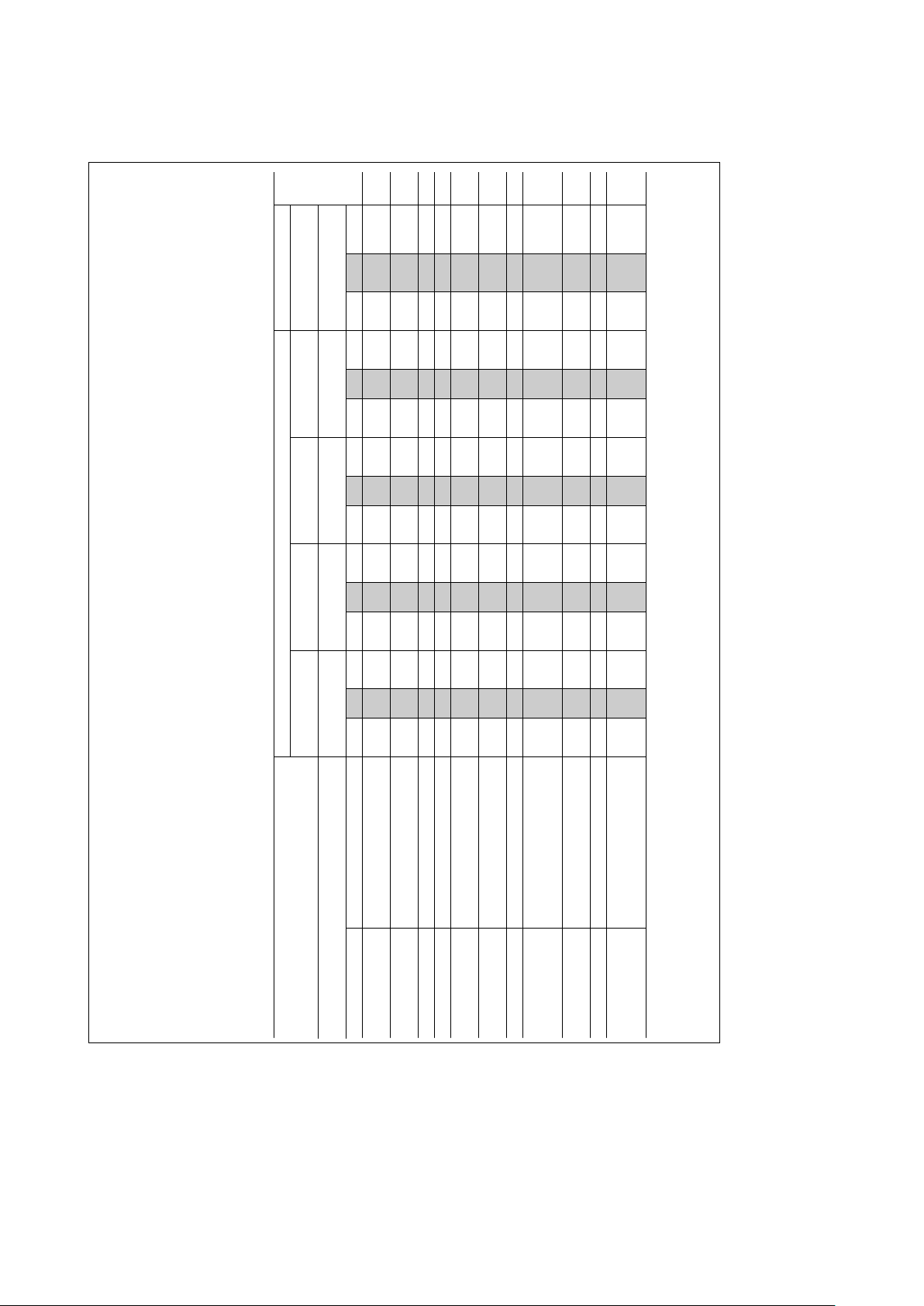
b
15 Volt Regulators
Absolute Maximum Ratings
If Military/Aerospace specified devices are required, Input-Output Voltage Differential 30V
please contact the National Semiconductor Sales
Junction Temperatures See Note 1
Office/Distributors for availability and specifications.
Storage Temperature Range
b
65
§
Cto
a
150
§
C
(Note 4)
Lead Temperature (Soldering, 10 sec.) 300
§
C
Power Dissipation Internally Limited
Input Voltage
LM120/LM320
b
40V
LM320T
b
35V
Electrical Characteristics
Metal Can Package Power Plastic Package
Order Numbers
LM120K-15 LM320K-15 LM120H-15 LM320H-15 LM320T-15
(TO-3) (TO-3) (TO-39) (TO-39) (TO-220)
Units
Design Output Current (I
D
) 1A 1A 0.2A 0.2A 1A
Device Dissipation (P
D
) 20W 20W 2W 2W 15W
Parameter Conditions (Note 1) Min Typ Max Min Typ Max Min Typ Max Min Typ Max Min Typ Max
Output Voltage T
J
e
25
§
C, V
IN
e
20V,
b
15.3
b
15
b
14.7
b
15.4
b
15
b
14.6
b
15.3
b
15
b
14.7
b
15.4
b
15
b
14.6
b
15.5
b
15
b
14.5 V
I
LOAD
e
5mA
Line Regulation T
J
e
25
§
C, I
LOAD
e
5 mA,
5 10 5 20 5 10 5 20 5 20 mV
V
MIN
s
V
IN
s
V
MAX
Input Voltage
b
35
b
17
b
35
b
17
b
35
b
17
b
35
b
17
b
35
b
17.5 V
Ripple Rejection f
e
120 Hz 56 80 56 80 56 80 56 80 56 80 dB
Load Regulation, T
J
e
25
§
C, V
IN
e
20V,
30 80 30 80 10 25 10 40 30 80 mV
(Note 2) 5 mA
s
I
LOAD
s
I
D
Output Voltage, 17.5V
s
V
IN
s
V
MAX
,
b
15.5
b
14.5
b
15.6
b
14.4
b
15.5
b
14.5
b
15.6
b
14.4
b
15.7
b
14.3 V
(Note 1) 5 mA
s
I
LOAD
s
I
D
,P
s
P
D
Quiescent Current V
MIN
s
V
IN
s
V
MAX
24 24 24 24 2 4 mA
Quiescent Current T
J
e
25
§
C
Change V
MIN
s
V
IN
s
V
MAX
0.1 0.4 0.1 0.4 0.05 0.4 0.05 0.4 0.1 0.4 mA
5mA
s
I
LOAD
s
I
D
0.1 0.4 0.1 0.4 0.03 0.4 0.03 0.4 0.1 0.4 mA
Output Noise Voltage T
A
e
25
§
C, C
L
e
1 mF, I
L
e
5 mA,
400 400 400 400 400 mV
V
IN
e
20V, 10 Hz
s
f
s
100 kHz
Long Term Stability 15 150 15 150 15 150 15 150 30 mV
Thermal Resistance
Junction to Case 3 3 Note 3 Note 3 4
§
C/W
Junction to Ambient 35 35 Note 3 Note 3 50
§
C/W
Note 1: This specification applies over
b
55
§
C
s
T
J
s
a
150
§
C for the LM120 and 0
§
C
s
T
J
s
a
125
§
C for the LM320.
Note 2: Regulation is measured at constant junction temperature. Changes in output voltage due to heating effects must be taken into account separately. To ensure constant junction temperature, low duty cycle, pulse testing is
used. The LM120/LM320 series does have low thermal feedback, improving line and load regulation. On all other tests, even though power dissipation is internally limited, electrical specifications apply only up to P
D
.
Note 3: Thermal resistance of typically 85
§
C/W (in 400 linear feet/min air flow), 224
§
C/W (in static air) junction to ambient, of typically 21
§
C/W junction to case.
Note 4: Refer to RETS120-15H drawing for LM120H-15 or RETS120-15K drawing for LM120K-15 military specifications.
4
 Loading...