


CNC

 C6/C64/C64T
PARAMETER MANUAL
BNP-B2267C(ENG)
MELDAS and MELSEC are registered trademarks of Mitsubishi Electric Corporation.
Microsoft and Windows are a registered trademark of Microsoft Corporation in the United States and/or other countries.
Other brands and product names throughout this manual are trademarks or registered trademarks of their respective holders.
Introduction
This manual is a guide of the parameters used with the CNC MELDAS C6/C64/C64T. This manual is written on the assumption that all machine parameters of the MELDAS
C6/C64/C64T are provided. However, the CNC may not necessarily be provided with all of the options. When the system is used, therefore, reference should be made to the
Specifications Manual issued by the machine maker.
Points to be observed when reading this manual
(1)This manual contains general descriptions as seen from the standpoint of NC (numerical control) and thus refer to the Instruction Manual issued by the machine maker for descriptions of individual machine tools.
The Instruction Manual issued by the machine maker takes precedence over this manual when any mention of "restrictions", "usable states" or such details are mentioned.
(2)As much information as possible on special procedures has been included in this manual, and it may be considered that any procedures not mentioned cannot be undertaken.
(3)Also refer to the following manuals.
•MELDAS C6/C64/C64T Instruction Manual........................................ BNP-B2259
•MELDAS C6/C64/C64T Programming Manual
(Machining center/Transfer machine system)........ |
BNP-B2260 |
•MELDAS C6/C64/C64T Programming Manual (Lathe system) .......... BNP-B2264
•MELDAS AC Servo MDS-B-Vx Series Servo Parameter Manual....... BNP-A2993
•MELDAS AC Servo MDS-C1 Series Specification Manual................. BNP-C3000
 CAUTION
For items described as "Restrictions" or "Usable State" in this manual, the Instruction Manual issued by the machine maker takes precedence over this manual.
Items that are not described must be interpreted as "not possible".
This manual is written on the assumption that all option functions are added. Refer to the Specifications Manual issued by the machine maker before starting use.
Refer to the manuals issued by the machine manufacturer for each machine tool explanation.
Some screens and functions may differ or may not be usable depending on the NC system version.
Precautions for Safety
Always read the Specifications Manual issued by the machine maker, this manual, related manuals and attached documents before installation, operation, programming, maintenance or inspection to ensure correct use. Understand this numerical controller, safety items and cautions before using the unit.
This manual ranks the safety precautions into "DANGER", "WARNING" and "CAUTION".
|
|
DANGER |
When the user may be subject to imminent fatalities or major injuries |
|
|
||
|
|
if handling is mistaken. |
|
|
|
|
When the user may be subject to fatalities or major injuries if |
|
|
|
|
|
|
WARNING |
|
|
|
||
|
|
handling is mistaken. |
|
|
|
|
When the user may be subject to injuries or when physical damage |
|
|
|
|
|
|
CAUTION |
|
|
|
||
|
|
may occur if handling is mistaken. |
|
|
|
|
|
Note that even items ranked as "  CAUTION", may lead to major results depending on the situation.
In any case, important information that must always be observed is described.
 DANGER
Not applicable in this manual.
 WARNING
Not applicable in this manual.
 CAUTION
1. Items related to product and manual
 For items described as "Restrictions" or "Usable State" in this manual, the Instruction Manual issued by the machine maker takes precedence over this manual.
 Items that are not described must be interpreted as "not possible".
 This manual is written on the assumption that all option functions are added. Refer to the Specifications Manual issued by the machine maker before starting use.
 Refer to the manuals issued by the machine manufacturer for each machine tool explanation.
 Some screens and functions may differ or may not be usable depending on the NC system version.

CAUTION
2. Items related to servo/spindle parameters
To change the control mode to the High-gain amp (MDS-B-V14/V24) mode after replacement of the Standard amp (MDS-B-V1/V2), it is need to change the parameters and to adjust the servo parameters to fit to the High-gain amp.
Mode change between the Standard amp mode and the High-gain amp mode is actually performed when the power (200V) is turned ON. Thus, when changing some parameters unique to each amp, an alarm “7F” occurs and requests to turn the power ON again.
Note that the alarm “7F” may occur when the amp is mounted on the machine for the first time.
When the alarm “7F” occurs, turn the power ON again.
The alarm “7F” may not occur at second turning ON or later unless the above-mentioned parameters are changed.
With MDS-C1 series, only the serial encoder is applied as the motor end detector. Thus, OHE/OHA type detector cannot be used as the motor end detector.
Do not make remarkable adjustments or changes of the parameters as the operation may became unstable.
3. Items related to the other parameters
When setting the parameter (#6449/bit6, 7) not to check the overheat, the control unit and the communication terminal may not be controlled because of overheat.
In such case, axis runaway may cause a machine breakage, an accident resulting in injury or death, or device breakage.
To prevent the serious results, ordinarily set the parameters so that the overheat check is valid.
|
|
|
CONTENTS |
|
1. Parameter Screens .................................................................................................................................. |
1 |
|||
2. Machining Parameters ............................................................................................................................. |
3 |
|||
|
2.1 |
Workpiece Coordinate Offset ......................................................................................................... |
3 |
|
|
2.2 |
Process Parameters....................................................................................................................... |
4 |
|
|
2.3 |
Control Parameters ........................................................................................................................ |
6 |
|
|
2.4 |
Axis Parameters ............................................................................................................................. |
7 |
|
|
2.5 |
Barrier Data .................................................................................................................................... |
8 |
|
3. |
I/O Parameters......................................................................................................................................... |
9 |
||
|
3.1 |
Base Parameters............................................................................................................................ |
9 |
|
|
3.2 |
I/O Device Parameters ................................................................................................................. |
10 |
|
4. Setup Parameters .................................................................................................................................. |
14 |
|||
5. |
Base Specifications Parameters............................................................................................................ |
15 |
||
6. |
Axis Specifications Parameters ............................................................................................................. |
66 |
||
|
6.1 |
Axis Specifications Parameters.................................................................................................... |
66 |
|
|
6.2 |
Zero Point Return Parameters ..................................................................................................... |
73 |
|
|
6.3 |
Absolute Position Parameters...................................................................................................... |
75 |
|
|
6.4 |
Axis Specifications Parameters 2................................................................................................. |
77 |
|
7. Servo Parameters .................................................................................................................................. |
80 |
|||
|
7.1 |
MDS-B-SVJ2 ................................................................................................................................ |
82 |
|
|
7.2 |
MDS-C1-Vx High-gain (MDS-B-Vx4 Compatible)...................................................................... |
108 |
|
|
7.3 |
MDS-C1-Vx Standard Specification (MDS-B-Vx Compatible) ................................................... |
136 |
|
|
7.4 |
Supplement ................................................................................................................................ |
166 |
|
|
|
7.4.1 |
D/A Output Specifications ................................................................................................ |
166 |
|
|
7.4.2 |
Electronic Gears .............................................................................................................. |
172 |
|
|
7.4.3 Lost Motion Compensation.............................................................................................. |
173 |
|
8. |
Spindle Parameters ............................................................................................................................. |
174 |
||
|
8.1 |
Spindle Base Specifications Parameters ................................................................................... |
174 |
|
|
8.2 |
MDS-B-SPJ2 .............................................................................................................................. |
181 |
|
|
8.3 |
MDS-B-SP/SPH, MDS-C1-SP/SPH ........................................................................................... |
201 |
|
|
8.4 |
MDS-C1-SPM............................................................................................................................. |
234 |
|
|
8.5 |
Supplement ................................................................................................................................ |
266 |
|
|
|
8.5.1 |
D/A Output Specifications ................................................................................................ |
266 |
9. Machine Error Compensation .............................................................................................................. |
269 |
|||
|
9.1 |
Function Outline ......................................................................................................................... |
269 |
|
|
9.2 |
Setting Compensation Data ....................................................................................................... |
273 |
|
|
9.3 |
Example in Using a Linear Axis as the Base Axis ..................................................................... |
275 |
|
|
9.4 |
Example in Using a Rotation Axis as the Base Axis .................................................................. |
277 |
|
10. PLC Constants................................................................................................................................... |
278 |
|||
|
10.1 PLC Timer ................................................................................................................................ |
278 |
||
|
10.2 PLC Counter............................................................................................................................. |
278 |
||
|
10.3 PLC Constants ......................................................................................................................... |
279 |
||
|
10.4 |
PLC Bit Selection ..................................................................................................................... |
280 |
|
11. |
Macro List |
........................................................................................................................................... |
283 |
|
12. |
Position Switch................................................................................................................................... |
284 |
||
|
12.1 |
Outline ...................................................................................................................of Function |
284 |
|
|
12.2 |
Canceling ..................................................................................................the Position Switch |
286 |
|
13. Indexing Axis ...................................................................................................................Parameters |
287 |
|||
14. Indexing Axis .............................................................................................................Position Switch |
289 |
|||
|
14.1 |
Outline ...................................................................................................................of Function |
289 |
|
15. Indexing Axis ...................................................................................................................Commands |
290 |
|||
16. |
Auxiliary Axis ..................................................................................................................Parameters |
291 |
||

1. Parameter Screens
1. Parameter Screens
The parameter input setting units are as follow.
Input unit |
Linear axis "#1017 rot"=0 |
Rotary axis |
||
Machine constant:mm |
Machine constant:inch |
|||
"#1003 iunit" |
"#1017 rot"=1 |
|||
|
"#1040 M_inch"=0 |
"#1040 M_inch"=1 |
|
|
B |
0.001 mm |
0.0001 inch |
0.001° |
|
|
|
|
|
|
C |
0.0001 mm |
0.00001 inch |
0.0001° |
|
|
|
|
|
|
(1)User parameters
The following menus can be selected when the key
TOOL
PARAM is pressed.
Menu |
Details |
|
Reference Section |
WORK |
The WORK OFFSET screen will open. |
2.1 |
Workpiece Coordinate |
|
|
|
Offset |
PROCESS |
The PROCESS PARAM screen will open. |
2.2 |
Process Parameters |
|
|
2.3 |
Control Parameters |
|
|
2.4 |
Axis Parameters |
|
|
2.5 |
Barrier Data |
I/O PARAM |
The I/O PARAM screen will open. |
3.1 |
Base Parameters |
|
|
3.2 |
I/O Device Parameters |
SETUP |
The screen to set the setup parameters will |
4. |
Setup Parameters |
|
open. |
|
|
1

1. Parameter Screens
(2)Setup Parameters
The following menus can be selected when SETUP is selected. (Refer to the section "4. Setup Parameters" for details.
|
Menu |
Details |
|
|
Reference Section |
|
|
BASE |
The BASE SPEC. PARAM screen will open. |
5. |
Base Specifications |
||
|
|
|
|
|
|
Parameters |
|
|
|
|
|
|
|
|
AXIS SPEC |
The AXIS SPEC PARAM screen will open. |
6. |
Axis Specifications |
||
|
|
|
|
|
|
Parameters |
|
|
|
|
|
|
|
|
SERVO |
The SERVO PARAM screen will open. |
|
7. |
Servo Parameters |
|
|
|
|
|
|
|
|
|
SPINDLE |
The SPINDLE BASE SPEC. PARAM screen will |
8. |
Spindle Parameters |
||
|
|
open. |
|
|
|
|
|
MC-ERR |
The MC-ERR. CMP. screen will open. |
|
9. |
Machine Error |
|
|
|
|
|
|
|
Compensation |
|
PLC |
The PLC DATA screen will open. |
|
10. |
PLC Constants |
|
|
|
|
|
|
|
|
|
MACRO |
The MACRO FILE screen will open. |
|
11. |
Macro List |
|
|
|
|
|
|
|
|
|
PSW |
The POSITION SWITCH screen will open. |
|
12. |
Position Switch |
|
|
|
|
|
|
|
|
|
IDX-PRM |
The INDEXING AXIS PARAMETERS screen will |
13. |
Indexing Axis Parameters |
||
|
|
open. |
|
|
|
|
|
|
|
|
|
|
|
|
IDX-PSW |
The INDEXING AXIS POSITION SWITCH |
|
14. |
Indexing Axis Position |
|
|
|
screen will open. |
|
|
Switch |
|
|
|
|
|
|
|
|
|
IDX-CMD |
The INDEXING AXIS COMMANDS screen will |
15. |
Indexing Axis Commands |
||
|
|
open. |
|
|
|
|
|
|
|
|
|
|
|
|
|
|
|
|
|
|
(3) The following menus can be selected when the key |
|
ALARM |
is pressed. |
|||
|
DIAGN |
|||||
|
|
|
|
|
|
|
|
Menu |
Details |
|
|
Reference Section |
|
|
|
|
|
|
|
|
|
AUX-PRM |
The AUX-PARA screen will open. |
|
16. |
Auxiliary Axis Parameter |
|
|
|
|
|
|
|
|
2
2.Machining Parameters
2.1Workpiece Coordinate Offset
2.Machining Parameters
2.1 Workpiece Coordinate Offset
# |
Parameter |
|
|
Explanation |
|
Setting range (unit) |
||
54 |
G54 offset |
Set the workpiece coordinate system and external |
±99999.999 (mm) |
|||||
|
|
workpiece coordinate offset values from G54 to G59. |
|
|||||
|
|
The workpiece coordinate system offset data can |
|
|||||
55 |
G55 offset |
|
||||||
be set as an absolute value or incremental value. |
|
|||||||
|
|
|
||||||
|
|
|
Basic machine |
|
M |
|
|
|
56 |
G56 offset |
|
|
|
|
|||
|
coordinate system |
|
|
|
||||
|
|
|
|
|
|
|
|
|
57 |
G57 offset |
|
|
|
External |
R |
|
|
|
|
G55 |
W2 |
|
(EXT) |
|
|
|
|
|
|
offset |
Reference |
|
|||
|
|
workpiece |
|
|
|
point |
|
|
58 |
G58 offset |
coordinate |
|
|
|
|
|
|
system |
|
|
|
|
|
|
||
|
|
|
|
|
|
|
|
|
|
|
|
G54 |
W1 |
|
|
|
|
59 |
G59 offset |
|
workpiece |
|
|
|
|
|
|
|
|
|
|
|
|||
|
coordinate |
|
|
|
|
|
||
|
|
|
|
|
|
|
|
|
|
|
|
system |
|
|
|
|
|
|
|
|
|
|
|
|
|
|
60 |
EXT offset |
|
|
|
|
|
|
|
|
|
|
|
|
|
|
|
|
3

2.Machining Parameters
2.2Process Parameters
2.2 Process Parameters
<WRK COUNT> (No. of workpieces machined)
# |
Item |
Contents |
Setting range (unit) |
8001 |
WRK COUNT M |
Set the M code that counts the No. of workpiece |
0 to 99 |
|
|
repeated machining. |
|
|
|
The No. will not be counted when set to 0. |
|
8002 |
WRK COUNT |
The current machining No. is displayed. Set the |
0 to 999999 |
|
|
initial value. |
|
|
|
|
|
8003 |
WRK LIMIT |
Set the maximum No. of workpieces machined. |
0 to 999999 |
|
|
A signal is output to PLC when the No. of machining |
|
|
|
times is counted to this limit. |
|
<AUTO TLM> (Automatic tool length measurement) |
|
||
|
|
|
|
# |
Item |
Contents |
Setting range (unit) |
8004 |
SPEED |
Set the feedrate during automatic tool length |
1 to 1000000 |
|
|
measurement. |
(mm/min) |
|
|
|
|
8005 |
ZONE r |
Set the distance between the measurement position |
0 to 99999.999 (mm) |
|
|
and deceleration start point. |
|
|
|
|
|
8006 |
ZONE d |
Set the tolerable zone of the measurement position. |
0 to 99999.999 (mm) |
|
|
If the sensor signal turns on in front of d before the |
|
|
|
measurement position‚ or if the signal does not turn |
|
|
|
on after d is passed‚ an alarm will occur. |
|
<AUTO CORNER OVR> (Automatic corner override) |
|
||
|
|
|
|
# |
Item |
Contents |
Setting range (unit) |
8007 |
OVERRIDE |
Set the override value for automatic corner override. |
0 to 100 (%) |
8008 |
MAX ANGLE |
Set the max. corner opening angle where deceler- |
0 to 180 (degrees) |
|
|
ation should start automatically. |
|
|
|
If the angle is larger than this value‚ deceleration will |
|
|
|
not start. |
|
|
|
|
|
8009 |
DSC. ZONE |
Set the position where deceleration starts at the |
0 to 99999.999 (mm) |
|
|
corner. |
|
|
|
Designate at which length point before the corner |
|
|
|
deceleration should start. |
|
<T-TIP OFFSET> (Wear data input) |
|
||
# |
Item |
Contents |
Setting range (unit) |
8010 |
ABS. MAX. |
Set the max. value when inputting the tool wear |
0 to 99.999 (mm) |
|
(For L system only) |
compensation amount. |
|
|
|
A value exceeding this setting value cannot be set. |
|
8011 |
INC. MAX. |
Set the max. value for when inputting the tool wear |
0 to 99.999 (mm) |
|
(For L system only) |
offset amount in the addition mode. |
|
|
|
|
|
4
2.Machining Parameters
2.2Process Parameters
<FIXED C.> (Fixed cycle)
# |
Item |
|
Contents |
Setting range (unit) |
|
8012 |
G73 n |
Set the return amount for G73 (step cycle). |
0 to 99999.999 (mm) |
||
|
(For M system only) |
|
|
|
|
|
|
|
|
|
|
8013 |
G83 n |
Set the return amount for G83 (deep hole drilling |
0 to 99999.999 (mm) |
||
|
|
cycle). |
|
||
|
|
|
|
|
|
8014 |
CDZ-VALE |
Set the screw cut up amount for G76‚ 78 (thread |
0 to 127 |
||
|
(For L system only) |
cutting cycle). |
(0.1 lead) |
||
|
|
|
|
|
|
8015 |
CDZ-ANGLE |
Set the screw cut up angle for G76‚ 78 (thread |
0 to 89 (degrees) |
||
|
(For L system only) |
cutting cycle). |
|
||
|
|
|
|
|
|
8016 |
G71 MINIMUM |
Set the minimum cut amount for the final cutting in |
0 to 99.999 (mm) |
||
|
(For L system only) |
G71‚ 72 (rough cutting cycle). |
|
||
|
|
If the final cutting amount is smaller than this value‚ |
|
||
|
|
the final cut will not be performed. |
|
||
8017 |
DELTA-D |
Set the change amount to the command cut amount |
0 to 99.999 (mm) |
||
|
(For L system only) |
D for G71‚ 72 (rough cutting cycle). |
|
||
|
|
Each cut amount will be the value obtained by |
|
||
|
|
adding or subtracting this value from command D‚ |
|
||
|
|
and thus‚ the amount can be changed each cut. |
|
||
8018 |
G84/G74 return |
Set up return length m at a G84/G74 pecking tap |
0 to 99.999 (mm) |
||
|
(For M system only) |
cycle. |
|
||
|
|
(Note) Set 0 to specify a usual tap cycle. |
|
||
<PRECISION> (High precision control) |
|
||||
|
|
|
|
|
|
# |
Item |
|
Contents |
Setting range (unit) |
|
8019 |
R COMP |
Set up a compensation factor for reducing a control |
0 to 99 (%) |
||
|
|
error in the reduction of a corner roundness and |
|
||
|
|
arch radius. |
|
||
|
|
Indicates a maximum control error (mm) in |
|
||
|
|
parentheses. |
|
||
|
|
The larger the setup value, the smaller the |
|
||
|
|
theoretical error will be. However, since the speed |
|
||
|
|
at the corner goes down, the cycle time is extended. |
|
||
|
|
|
|
|
|
8020 |
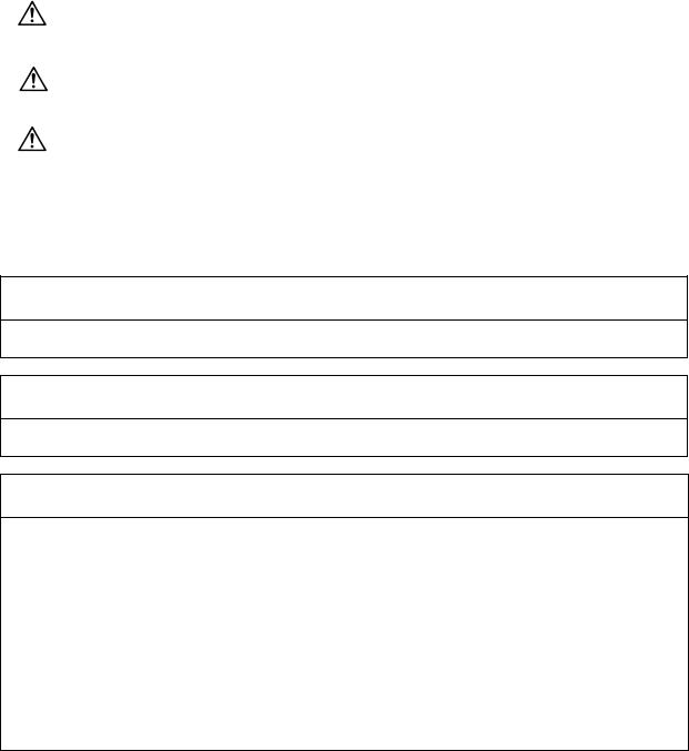
DCC ANGLE |
Set up the minimum value of an angle (external |
0 to 30 (degrees) |
||
|
|
angle) that should be assumed to be a corner. |
0: The angle will be 5 |
||
|
|
When an inter-block angle (external angle) in high- |
degrees. |
||
|
|
precision mode is larger than the set value, it is |
|
||
|
|
determined as a corner and the speed goes down to |
|
||
|
|
sharpen the edge. |
|
||
|
|
|
|
|
|
|
|
θ |
If the set value is smaller than |
|
|
|
|
θ, the speed goes down to |
|
|
|
|
|
|
optimize the corner. |
|
|
|
|
|
|
|
|
|
|
(Note) If “0” is set, it will be handled as 5 degrees. |
|
||
|
|
The standard setting value is “0”. |
|
||
5

2.Machining Parameters
2.3Control Parameters
2.3 Control Parameters
# |
Item |
Contents |
Setting range (unit) |
8101 |
MACRO SINGLE |
Select the control of the blocks where the user |
0/1 |
|
|
macro command continues. |
|
|
|
0: Do not stop while macro block continues. |
|
|
|
1: Stop every block during signal block operation. |
|
8102 |
COLL. ALM OFF |
Select the interference (bite) control to the |
0/1 |
|
|
workpiece from the tool diameter during cutter |
|
|
|
compensation and nose R offset. |
|
|
|
0: An alarm is output and operation stops when |
|
|
|
an interference is judged. |
|
|
|
1: Changes the path to avoid interference. |
|
|
|
|
|
8103 |
COLL. CHK OFF |
Select the interference (bite) control to the work |
0/1 |
|
|
from the tool diameter during cutter compensation |
|
|
|
and nose R offset. |
|
|
|
0: Performs interference check |
|
|
|
1: Does not perform interference check |
|
|
|
|
|
8105 |
EDIT LOCK B |
Select the edit lock for program Nos. 8000 to 9999. |
0/1 |
|
|
0: Program can be edited. |
|
|
|
1: Editing of above program is prohibited. |
|
|
|
|
|
8106 |
G46 NO REV-ERR |
Select the control for the compensation direction |
0/1 |
|
(For L system only) |
reversal in G46 (nose R offset). |
|
|
|
0: An alarm is output and operation stops when |
|
|
|
the compensation direction is reversed (G41 |
|
|
|
→ G42‚ G42 → G41). |
|
|
|
1: An alarm does not occur when the compensa- |
|
|
|
tion direction is reversed‚ and the current |
|
|
|
compensation direction is maintained. |
|
|
|
|
|
8107 |
R COMPENSATION |
0: In arc cutting mode, the machine moves to the |
0/1 |
|
|
inside because of a delay in servo response to |
|
|
|
a command, making the arc smaller than the |
|
|
|
command value. |
|
|
|
1: In arc cutting mode, the machine compensates |
|
|
|
the movement to the inside because of a delay |
|
|
|
in servo response to a command |
|
8108 |
R COMP Select |
Specify whether to perform arc radius error |
0/1 |
|
|
correction over all axes or axis by axis. |
|
|
|
0: Perform correction over all axes. |
|
|
|
1: Perform correction over axis by axis. |
|
|
|
(Note) This parameter is effective only when |
|
|
|
"#8107 R COMPENSATION" is 1. |
|
8109 |
HOST LINK |
Not used. |
0 |
6

2.Machining Parameters
2.4Axis Parameters
2.4 Axis Parameters
# |
Item |
Contents |
Setting range (unit) |
8201 |
AX. RELEASE |
Select the function to remove the control axis from |
0/1 |
|
|
the control target. |
|
|
|
0: Control as normal |
|
|
|
1: Remove from control target |
|
8202 |
OT-CHECK OFF |
Select the stored stroke limit function set in #8204 |
0/1 |
|
|
and #8205. |
|
|
|
0: Stored stroke limit valid |
|
|
|
1: Stored stroke limit invalid |
|
|
|
|
|
8203 |
OT-CHECK-CANCEL |
When the simple absolute position method ("#2049 |
0/1 |
|
|
type" is 9) is selected‚ the stored stroke limits I, II (or |
|
|
|
IIB) and IB will be invalid until the first reference |
|
|
|
point return is executed after the power is turned on. |
|
|
|
0: Stored stroke limit II valid (according to #8202) |
|
|
|
1: Stored stroke limit II invalid |
|
|
|
(Note) This setting (#8203) affects all the stored |
|
|
|
stroke limits. |
|
|
|
|
|
8204 |
OT-CHECK-N |
Set the coordinates of the (–) direction in the |
–99999.999 to |
|
|
moveable range of the stored stroke limit II or the |
+99999.999 (mm) |
|
|
lower limit coordinates of the prohibited range of |
|
|
|
stored stroke limit IIB. |
|
|
|
If the sign and value are the same as #8205 (other |
|
|
|
than "0"), the stored stroke limit II (or IIB) will be |
|
|
|
invalid. |
|
|
|
If the stored stroke limit IIB function is selected, the |
|
|
|
prohibited range will be between two points even |
|
|
|
when #8204 and #8205 are set in reverse. |
|
|
|
When II is selected, the entire range will be |
|
|
|
prohibited. |
|
8205 |
OT-CHECK-P |
Set the coordinates of the (+) direction in the |
–99999.999 to |
|
|
moveable range of the stored stroke limit II or the |
+99999.999 (mm) |
|
|
upper limit coordinates of the prohibited range of |
|
|
|
stored stroke limit IIB. |
|
|
|
|
|
8206 |
TOOL CHG. P |
Set the coordinates of the tool change position for |
–99999.999 to |
|
|
G30. n (tool change position return). |
+99999.999 (mm) |
|
|
Set with coordinates in the basic machine coordinate |
|
|
|
system. |
|
|
|
|
|
8207 |
G76/87 IGNR |
Select the shift operation at G76 (fine boring) and |
0/1 |
|
(For M system only) |
G87 (back boring). |
|
|
|
0: Shift effective |
|
|
|
1: No shift |
|
7

2.Machining Parameters
2.5Barrier Data
# |
Item |
Contents |
Setting range (unit) |
8208 |
G76/87 (–) |
Specify the shift direction at G76 and G87. |
0/1 |
|
(For M system only) |
0: Shift to (+) direction |
|
|
|
1: Shift to (–) direction |
|
8209 |
G60 SHIFT |
Set the last positioning direction and distance for a |
–99999.999 to |
|
(For M system only) |
G60 (uni-directional positioning) command. |
+99999.999 (mm) |
8210 |
OT INSIDE |
The stored stoke limit function set in #8204 and |
0/1 |
|
|
#8205 prevents the machine from moving to the |
|
|
|
inside or outside of the specified range. |
|
|
|
0: Inhibits outside area. |
|
|
|
(select stored stroke limit II.) |
|
|
|
1: Inhibits inside area. |
|
|
|
(select stored stroke limit II B.) |
|
|
|
|
|
2.5 Barrier Data
# |
Item |
Contents |
Setting range (unit) |
8300 |
P0 |
Set the reference X-coordinates of the chuck and |
–99999.999 to |
|
(For L system only) |
the tail stock barrier. |
+99999.999 (mm) |
|
|
Set the center coordinate (Radius value) of |
|
|
|
workpiece by the basic machine coordinate system. |
|
|
|
|
|
8301 |
P1 |
Set the area of the chuck and tail stock barrier. |
–99999.999 to |
8302 |
P2 |
(Radius value) |
+99999.999 (mm) |
8303 |
P3 |
Set the coordinate value from the center of workpiece |
|
8304 |
P4 |
for X-axis. |
|
8305 |
P5 |
Set the coordinate value by basic machine |
|
8306 |
P6 |
coordinate system for Z-axis. |
|
|
(For L system only) |
|
|
|
|
|
|
8

3.I/O Parameters
3.1Base Parameters
3. I/O Parameters
3.1 Base Parameters
<I/O> |
# |
<PORT No.> |
# |
<DEV. No.> <DEV. NAME> |
|
|
Specify the board No. to which the serial |
|
Set the input/output device No. for |
|
|
input/output device is connected to each |
|
each application. |
|
|
application. |
|
The device Nos. are 0 to 4 and |
|
|
|
|
correspond to the input/output |
|
|
|
|
device parameters. |
|
|
|
|
The device name set in the |
|
|
|
|
input/output device parameter is |
|
|
|
|
also displayed for identification. |
|
|
|
|
|
DATA IN |
9001 |
Specify the port for inputting the data |
9002 |
Specify the No. of the device that |
|
|
such as machine program and |
|
inputs the data. |
|
|
parameters. |
|
|
|
|
|
|
|
DATA OUT |
9003 |
Specify the port for outputting the data |
9004 |
Specify the No. of the device that |
|
|
such as machine program and |
|
outputs the data. |
|
|
parameters. |
|
|
TAPE MODE |
9005 |
Specify the input port for running with |
9006 |
Specify the No. of the device to be |
|
|
the tape mode. |
|
run with the tape mode. |
|
|
|
|
|
MACRO |
9007 |
Specify the output port for the user |
9008 |
Specify the No. of the device for the |
|
macro DPRINT command. |
|
DPRINT command. |
|
|
|
|
|
|
PLC IN/OUT |
9009 |
Specify the port for inputting/outputting |
9010 |
Specify the No. of the device for the |
|
|
various data with PLC. |
|
PLC input/output. |
|
|
|
|
|
REMOTE |
9011 |
Not used. |
9012 |
Not used. |
PROG IN |
|
|
|
|
|
|
|
|
|
9

3.I/O Parameters
3.2I/O Device Parameters
3.2 I/O Device Parameters
Parameters for up to five types of input/output devices can be set in DEV <0> to <4>.
(Note) The parameters are set for each device.
|
|
9101 ~ |
Set the same settings for device 0. |
|
|
|
|
|
9201 ~ |
Set the same settings for device 1. |
|
|
|
|
|
9301 ~ |
Set the same settings for device 2. |
|
|
|
|
|
9401 ~ |
Set the same settings for device 3. |
|
|
|
|
|
9501 ~ |
Set the same settings for device 4. |
|
|
|
|
|
|
|
|
||
# |
|
Item |
Contents |
Setting range (unit) |
||
9101 |
DEVICE NAME 0 |
Set the device name corresponding to the device |
Use alphabet |
|||
9201 |
DEVICE NAME 1 |
No. |
characters‚ numerals |
|||
9301 |
DEVICE NAME 2 |
Set a simple name for quick identification. |
and symbols to set a |
|||
9401 |
DEVICE NAME 3 |
|
|
name within 3 |
||
9501 |
DEVICE NAME 4 |
|
|
characters. |
||
|
|
|
|
|||
9102 |
BAUD RATE |
Set the serial communication speed. |
1: 9600 (bps) |
|||
9202 |
|
|
|
|
2: 4800 |
|
9302 |
|
|
|
|
3: 2400 |
|
9402 |
|
|
|
|
4: 1200 |
|
9502 |
|
|
|
|
5: |
600 |
|
|
|
|
|
6: |
300 |
|
|
|
|
|
7: |
150 |
9103 |
STOP BIT |
Set the stop bit length used in the start-stop system. |
1: |
1 (bit) |
||
9203 |
|
|
|
|
2: |
1.5 |
9303 |
|
|
|
|
3: |
2 |
9403 |
|
|
|
|
|
|
9503 |
|
|
|
|
|
|
9104 |
PARITY CHECK |
Specify whether to add the parity check bit to the |
0: Parity bit not added |
|||
9204 |
|
|
data during communication. |
1: Parity bit added |
||
9304 |
|
|
|
|
|
|
9404 |
|
|
|
|
|
|
9504 |
|
|
|
|
|
|
|
|
|
|
|||
9105 |
EVEN PARITY |
Specify the odd or even parity when it is added to |
0: Odd parity |
|||
9205 |
|
|
the data. |
1: Even parity |
||
9305 |
|
|
|
|
|
|
9405 |
|
|
|
|
|
|
9505 |
|
|
|
|
|
|
|
|
|
|
|
||
9106 |
CHR. LENGTH |
Set the length of the data bit. |
0: |
5 (bit) |
||
9206 |
|
|
|
|
1: |
6 |
9306 |
|
|
|
|
2: |
7 |
9406 |
|
|
|
|
3: |
8 |
9506 |
|
|
|
|
|
|
|
|
|
|
|
|
|
10

3.I/O Parameters
3.2I/O Device Parameters
# |
Item |
Contents |
Setting range (unit) |
9107 |
TERMINATOR TYPE |
The code to terminate data reading can be selected. |
0 and 3: EOR |
9207 |
|
|
1 and 2: EOB or EOR |
9307 |
|
|
|
9407 |
|
|
|
9507 |
|
|
|
9108 |
HAND SHAKE |
Specify the transmission control method. |
1: RTS/CTS method |
9208 |
|
The method will be no procedure if a value except 1 |
(This method can |
9308 |
|
to 3 is set. |
be used only for |
9408 |
|
|
SIO2.) |
9508 |
|
|
2: No procedure (No |
|
|
|
handshaking) |
|
|
|
3: DC code method |
9109 |
DC CODE PARITY |
Specify the DC code when the DC code method is |
0: No parity to DC |
9209 |
|
selected. |
code (DC3 = 13H) |
9309 |
|
|
1: DC code with parity |
9409 |
|
|
(DC3 = 93H) |
9509 |
|
|
|
|
|
|
|
9111 |
DC2/DC4 OUTPUT |
Specify the DC code handling when outputting data |
DC2 / DC4 |
9211 |
|
to the output device. |
0: None / None |
9311 |
|
|
1: Yes / None |
9411 |
|
|
2: None / Yes |
9511 |
|
|
3: Yes / Yes |
|
|
|
|
9112 |
CR OUTPUT |
Specify whether to insert the <CR> code just before |
0: Do not add |
9212 |
|
the EOB (L/F) code during output. |
1: Add |
9312 |
|
|
|
9412 |
|
|
|
9512 |
|
|
|
|
|
|
|
9113 |
EIA Output |
In data output mode, select the ISO or EIA code for |
0: ISO code output |
9213 |
|
data output. |
1: EIA code output |
9313 |
|
In data input mode, the ISO and EIA codes are |
|
9413 |
|
identified automatically. |
|
9513 |
|
|
|
9114 |
FEED CHR. |
Specify the length of the tape feed to be output at |
0 to 999 (characters) |
9214 |
|
the start and end of the data during tape output. |
|
9314 |
|
|
|
9414 |
|
|
|
9514 |
|
|
|
9115 |
PARITY V |
Specify whether to check the parity of the No. of |
0: Do not perform |
9215 |
|
characters in block during data input. |
parity V check |
9315 |
|
The No. of characters is factory-set so that the |
1: Perform parity V |
9415 |
|
check is valid at all times. |
check |
9515 |
|
|
|
11

3.I/O Parameters
3.2I/O Device Parameters
# |
Item |
Contents |
Setting range (unit) |
9116 |
TIME-OUT (s) |
Set the time out time to detect an interruption in |
0 to 30 (s) |
9216 |
|
communication. |
|
9316 |
|
The time out is not checked when 0 is set, so the |
|
|
waiting time will be infinite. |
|
|
9416 |
|
|
|
|
The screens cannot be changed during the waiting |
|
|
9516 |
|
|
|
|
time. |
|
|
|
|
|
|
|
|
Set this time to 10 as the standard. |
|
|
|
|
|
9117 |
DR OFF |
Specify whether to check the DR data at the data |
0: DR valid |
9217 |
|
input/output. |
1: DR invalid |
9317 |
|
|
|
9417 |
|
|
|
9517 |
|
|
|
|
|
|
|
9118 |
DATA ASC II |
0: Output in ISO/EIA code (Depends on whether |
0/1 |
9218 |
|
#9113, #9213, #9313, #9413, or #9513 EIA |
|
9318 |
|
output parameter is set up) |
|
9418 |
|
1: Output in ASC II code |
|
9518 |
|
|
|
|
|
|
|
9119 |
INPUT FORM |
Specify the mode for input (collation). |
0/1 |
9219 |
|
0: Standard input (Data from the very first EOB is |
|
9319 |
|
handled as significant information.) |
|
9419 |
|
1: EOBs following the first EOB of the input data |
|
9519 |
|
are skipped until data other than EOB is input. |
|
|
|
|
|
9121 |
EIA CODE [ |
When outputting with the EIA codes, special ISO |
0 to FF (hexadecimal) |
9221 |
|
codes not included in EIA can be output with |
|
9321 |
|
alternate codes. |
|
|
For each special code, designate a code (as a |
|
|
9421 |
|
|
|
|
hexadecimal) that is not duplicated with existing EIA |
|
|
9521 |
|
|
|
|
codes. |
|
|
|
|
|
|
|
|
(Continued on the next page.) |
|
|
|
|
|
9122 |
] |
|
|
9222 |
|
|
|
9322 |
|
|
|
9422 |
|
|
|
9522 |
|
|
|
|
|
|
|
9123 |
# |
|
|
9223 |
|
|
|
9323 |
|
|
|
9423 |
|
|
|
9523 |
|
|
|
|
|
|
|
9124 |
|
|
|
9224 |
|
|
|
9324 |
|
|
|
9424 |
|
|
|
9524 |
|
|
|
|
|
|
|
12

3.I/O Parameters
3.2I/O Device Parameters
# |
Item |
Contents |
Setting range (unit) |
9125 |
= |
(Continued from the previous page.) |
|
9225 |
|
|
|
9325 |
|
|
|
9425 |
|
|
|
9525 |
|
|
|
9126 |
: |
|
|
9226 |
|
|
|
9326 |
|
|
|
9426 |
|
|
|
9526 |
|
|
|
9127 |
$ |
|
|
9227 |
|
|
|
9327 |
|
|
|
9427 |
|
|
|
9527 |
|
|
|
9128 |
! |
|
|
9228 |
|
|
|
9328 |
|
|
|
9428 |
|
|
|
9528 |
|
|
|
13
4. Setup Parameters
4. Setup Parameters
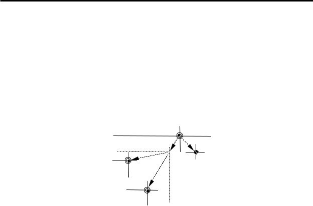
Pressing the menu key SETUP displays the OPEN SETUP PARAM screen.
The system’s basic parameters are normally hidden as setup parameters to prevent mistaken operations and to simplify the display.
The setup parameters can be displayed and set by making a declaration to open the setup parameters on this screen.
[OPEN SETUP PARAM] |
|
PARAM 3 |
Open the menu setup parameter? *YES: "Y" "INPUT"
*NO : "N" "INPUT"
# ( |
) |
|
|
|
|
WORK |
PROCESS I/O PAR |
SETUP |
MENU |
1)Select the setup parameter.
Key-in Y in # ( )‚ and then press INPUT .
The basic specification parameter screen appears and the normally hidden setup parameter menu will display.
The required menu can be selected to display and set the setup parameters.
2)Cancel the setup parameter selection. Key-in N in # ( )‚ and then press INPUT . The setup parameter menu will disappear.
(Note) The setup parameters are not displayed when the power is turned on.
Refer to "5. Base Specifications Parameters" and following for details on the setup parameters. Be sure to turn off the power supply after selecting the setup parameter.
14
5.Base Specifications Parameters
5.Base Specifications Parameters
After setting up the parameter (PR) listed in the table, turn off the NC power. To validate the parameter, turn on the power again.
# |
|
Items |
|
Details |
Setting range (unit) |
|||||
1001 |
SYS_ON Part system |
Specify the presence of the PLC axes and the 1st to |
0: Not used |
|||||||
(PR) |
|
validation |
7th part systems with 1 or 0. |
1: Used |
|
|
||||
|
|
setup |
|
|
|
|
|
|
|
|
1002 |
axisno |
Number of |
Set No. of axes in each part system and the No. of PLC |
0 to 14 |
|
|
||||
(PR) |
|
axes |
axes. |
|
|
|
|
|
|
|
|
|
|
Set so that the total of the NC axes and PLC axes is |
|
|
|
|
|
|
|
|
|
|
less than the maximum number of controllable axes. |
|
|
|
|
|
|
|
|
|
|
|
|
|
|
|
|
|
|
1003 |
iunit |
Input setup |
Specify the input setting value for each part system |
B: |
1 µm |
|
|
|||
(PR) |
|
unit |
and the PLC axis. The parameter units will follow this |
C: |
0.1 µm |
|||||
|
|
|
specification. |
|
|
|
|
|
|
|
1013 |
axname Axis name |
Specify each axis’ name address with an alphabetic |
Axis addresses |
|||||||
|
|
|
character. |
|
such as X, Y, Z, U, |
|||||
|
|
|
Use the characters X‚ Y‚ Z‚ U‚ V‚ W‚ A‚ B or C. |
V, W, A, B, and C |
||||||
|
|
|
Do not specify the same address in one part system. |
|
|
|
|
|
|
|
|
|
|
The same address can be specified as the other part |
|
|
|
|
|
|
|
|
|
|
system. |
|
|
|
|
|
|
|
|
|
|
The PLC address does not need to be set. (The axis |
|
|
|
|
|
|
|
|
|
|
name is displayed as 1 and 2.) |
|
|
|
|
|
|
|
|
|
|
|
|
|
|
|
|
|
|
1014 |
incax |
Increment |
When specifying the program movement rate’s |
|
|
|
|
|
|
|
|
|
command |
absolute or incremental method with an address‚ |
|
|
|
|
|
|
|
|
|
axis name |
specify the incremental command axis name address |
|
|
|
|
|
|
|
|
|
|
with an alphabetic character. |
|
|
|
|
|
|
|
|
|
|
The address that can be used is the same as "#1013 |
|
|
|
|
|
|
|
|
|
|
axname". |
|
|
|
|
|
|
|
|
|
|
Specify an address that is different from that #1013. |
|
|
|
|
|
|
|
|
|
|
Setting is not required if absolute/incremental command |
|
|
|
|
|
|
|
|
|
|
with addresses is not performed ("#1076 Abslnc" = 0). |
|
|
|
|
|
|
|
1015 |
cunit |
Command |
Specify the minimum unit of the program movement |
|
|
|
|
|
|
|
|
|
10 |
|
1 µm |
|
|||||
(PR) |
|
unit |
amount. |
|
|
|
|
|
||
|
|
|
|
|
|
|
|
|||
|
|
|
|
100 |
|
10 µm |
|
|||
|
|
|
cunit Movement amount for movement command 1 |
|
|
|
|
|||
|
|
|
|
|
|
|
|
|
||
|
|
|
|
|
1000 |
|
100 µm |
|
||
|
|
|
10: 0.001 mm ( 1 µm) |
|
|
|
|
|||
|
|
|
|
|
|
|
|
|
||
|
|
|
100: 0.01 |
mm ( 10 µm) |
|
|
10000 |
|
1 mm |
|
|
|
|
|
|
|
|
|
|
||
|
|
|
1000: 0.1 |
mm (100 µm) |
|
|
|
|
|
|
|
|
|
10000: 1.0 |
mm |
|
|
|
|
|
|
|
|
|
If there is a decimal point in the movement command‚ |
|
|
|
|
|
|
|
|
|
|
the decimal point position will be handled as 1mm |
|
|
|
|
|
|
|
|
|
|
regardless of this setting. |
|
|
|
|
|
|
|
1016 |
iout |
Inch output |
Specify whether the machine system (ball screw pitch‚ |
0: Metric unit |
||||||
(PR) |
|
|
position detection unit) is an inch unit system or metric |
|
|
system |
|
|
||
|
|
|
unit system. |
|
1: Inch unit system |
|||||
|
|
|
|
|
|
|
|
|
|
|
15

5. Base Specifications Parameters
# |
|
Items |
Details |
Setting range (unit) |
|
1017 |
rot |
Rotational |
Specify whether the axis is a rotary axis or linear axis. |
0: Linear axis |
|
(PR) |
|
axis |
For the rotary axis‚ the position display will be 360 |
1: Rotary axis |
|
|
|
|
degrees‚ and the axis will return to 0 degrees. |
|
|
|
|
|
If the position display is to be continuously displayed |
|
|
|
|
|
even with the rotary axis‚ set the axis as a linear axis |
|
|
1018 |
ccw |
Motor CCW |
Specify the direction of the motor rotation to the |
0: |
Rotates |
(PR) |
|
|
command direction. |
|
clockwise |
|
|
|
0: Rotates clockwise (looking from motor shaft) with |
1: |
Rotates |
|
|
|
the forward rotation command. |
|
counter- |
|
|
|
1: Rotates counterclockwise (looking from motor |
|
clockwise |
|
|
|
shaft) with the forward rotation command. |
|
|
|
|
|
|
|
|
1019 |
dia |
Diameter |
Specify whether the program movement amount is to |
0: |
Command with |
(PR) |
|
specification |
be commanded with the diameter dimension or as |
|
movement |
|
|
axis |
movement amount. |
|
amount |
|
|
|
When the movement amount is commanded with the |
1: |
Command with |
|
|
|
diameter dimensions‚ 5mm will be moved when the |
|
diameter |
|
|
|
command is a movement distance of 10mm. |
|
dimension |
|
|
|
The movement amount per pulse will also be halved |
|
|
|
|
|
during manual pulse feed. |
|
|
|
|
|
Among parameters concerning length‚ the tool length‚ |
|
|
|
|
|
the wear compensation amount and the workpiece |
|
|
|
|
|
coordinate offset are displayed in diameter value when |
|
|
|
|
|
diameter is specified‚ but other parameters are always |
|
|
|
|
|
displayed in radius value. |
|
|
|
|
|
|
|
|
1020 |
sp_ax |
Spindle |
Specify 1 when the NC control axis is used as the |
0: |
The NC control |
(PR) |
|
Interpolation |
spindle. |
|
axis is used as |
|
|
|
|
|
the servo axis. |
|
|
|
|
1: |
The NC control |
|
|
|
|
|
axis is used as |
|
|
|
|
|
the spindle. |
|
|
|
|
|
|
16

5. Base Specifications Parameters
# |
|
Items |
Details |
Setting range (unit) |
|
1025 |
l_plane |
Initial plane |
Specify the plane to be selected when the power is |
1: |
X-Y plane (G17 |
|
|
selection |
turned on or reset. |
|
command state) |
|
|
|
When 0 is specified, 1 is assumed (X-Y plane). |
2: |
Z-X plane (G18 |
|
|
|
|
|
command state) |
|
|
|
|
3: |
Y-Z plane (G19 |
|
|
|
|
|
command state) |
|
|
|
|
|
|
1026 |
base_l |
Base axis I |
Specify the basic axis address that composes the |
Control axis |
|
1027 |
base_J |
Base axis J |
plane. |
addresses such as |
|
1028 |
base_K |
Base axis K |
Specify the axis address set in “#1013 axname”. |
X, Y, and Z |
|
|
|
|
Set the axis name even when there is no need to |
|
|
|
|
|
configure a plane, such as the case of 2-axis |
|
|
|
|
|
specifications. |
|
|
|
|
|
Normally‚ when X‚ Y and Z are specified respectively |
|
|
|
|
|
for base_l‚_J‚_K‚ the following relation will be |
|
|
|
|
|
established: |
|
|
|
|
|
G17: X-Y |
|
|
|
|
|
G18: Z-X |
|
|
|
|
|
G19: Y-Z |
|
|
|
|
|
Specify the desired address to set an axis address |
|
|
|
|
|
other than the above. |
|
|
|
|
|
|
|
|
1029 |
aux_I |
Flat axis I |
If there is an axis parallel to "#1026 base_l"‚ specify |
Control axis |
|
|
|
|
that axis address. |
addresses such as |
|
|
|
|
|
X, Y, and Z |
|
|
|
|
|
|
|
1030 |
aux_J |
Flat axis J |
If there is an axis parallel to "#1027 base_J"‚ specify |
Control axis |
|
|
|
|
that axis address. |
addresses such as |
|
|
|
|
|
X, Y, and Z |
|
|
|
|
|
|
|
1031 |
aux_K |
Flat axis K |
If there is an axis parallel to "#1028 base_K"‚ specify |
Control axis |
|
|
|
|
that axis address. |
addresses such as |
|
|
|
|
|
X, Y, and Z |
|
17
5. Base Specifications Parameters
# |
Items |
|
|
Details |
Setting range (unit) |
||
1037 |
cmdtyp Command |
Specify the program G code series and compensation |
1 to 8 |
||||
|
type |
type. |
|
|
|
|
|
|
|
|
|
|
|
|
|
|
|
|
cmdtyp |
G code series |
Compensation type |
|
|
|
|
|
1 |
System 1 (for M) |
Type A (one compensation |
|
|
|
|
|
|
|
amount for one compen- |
|
|
|
|
|
|
|
sation number) |
|
|
|
|
|
2 |
System 2 (for M) |
Type B (shape and wear |
|
|
|
|
|
|
|
amounts for one compen- |
|
|
|
|
|
|
|
sation number) |
|
|
|
|
|
|
|
|
|
|
|
|
|
3 |
System 2 (for L) |
Type C (two kinds of |
|
|
|
|
|
|
compensation amount of |
|
|
|
|
|
|
|
|
shape and wear per |
|
|
|
|
|
|
|
compensation No.) |
|
|
|
|
|
|
|
|
|
|
|
|
|
|
System 3 (for L) |
Same as above |
|
|
|
|
|
4 |
|
|
|
|
|
|
|
|
|
|
|
|
|
|
|
5 |
System 4 |
Same as above |
|
|
|
|
|
(for special L) |
|
|
|
|
|
|
|
|
|
|
|
|
|
|
|
6 |
System 5 |
Same as above |
|
|
|
|
|
(for special L) |
|
|
|
|
|
|
|
7 |
System 6 |
Same as above |
|
|
|
|
|
(for special L) |
|
|
|
|
|
|
|
|
|
|
|
|
|
|
|
8 |
System 7 |
Same as above |
|
|
|
|
|
(for special L) |
|
|
|
|
There are some items in the specifications that can be used or cannot be used according to the value set in this parameter.
The file structure may also change depending on the compensation data type.
Thus‚ after changing this parameter‚ initialize the system with "#1060 SETUP".
|
# (1060) DATA ( 1) ( ) |
INPUT |
|
|
↓ |
|
|
|
"BASE PARA SET? (Y/N)" : N |
|
|
|
INPUT |
|
|
|
↓ |
|
|
|
|
|
|
|
"FORMAT? (Y/N)" : Y |
|
|
|
INPUT |
|
|
|
↓ |
|
|
|
|
|
|
|
"SETUP COMPLETE" |
|
|
|
(Note) The machining program is cleared with the |
||
|
above operations. Back up necessary |
||
|
machining programs in an external memory |
||
|
before initializing. |
|
|
1038 plcsel Ladder |
Specify the PLC type. |
|
0 to 2 |
selection |
|
|
|
18

5. Base Specifications Parameters
# |
|
Items |
|
|
|
Details |
|
Setting range (unit) |
||||
1039 |
spinno |
Number of |
|
Specify the existence of a spindle. |
|
0 to 7 |
||||||
|
|
spindles |
|
0: No spindle |
4: Four spindles |
|
|
|
|
|||
|
|
|
|
|
1: One spindle |
5: Five spindles |
|
|
|
|
||
|
|
|
|
|
2: Two spindles |
6: Six spindles |
|
|
|
|
||
|
|
|
|
|
3: Three spindles |
7: Seven spindles |
|
|
|
|
||
1040 |
M_inch Constant |
|
Specify the parameter unit system for the position and |
0: |
Metric system |
|||||||
(PR) |
|
input (inch) |
|
length. |
|
|
|
|
1: |
Inch system |
||
|
|
|
|
|
|
|
|
|
|
|
||
1041 |
l_inch |
Initial state |
|
Specify the unit system for the program movement |
0: |
Metric system |
||||||
(PR) |
|
(inch) |
|
amount when the power is turned on or reset and for |
1: |
Inch system |
||||||
|
|
|
|
|
position display. |
|
|
|
|
|
|
|
|
|
|
|
|
|
|
|
|
|
|
||
1042 |
pcinch |
PLC axis |
|
Specify the unit system for the commands to the PLC |
0: |
Metric system |
||||||
(PR) |
|
command |
|
axis. |
|
|
|
|
1: |
Inch system |
||
|
|
(inch) |
|
|
|
|
|
|
|
|
|
|
|
|
|
|
|
|
|
|
|
|
|
||
1043 |
lang |
Select |
|
Specify the display language. |
|
0/1/21 |
|
|||||
|
|
language |
|
0 : |
Japanese display |
|
|
|
|
|||
|
|
displayed |
|
1 : |
English display |
|
|
|
|
|
|
|
|
|
|
|
|
21: Polish display |
|
|
|
|
|
|
|
|
|
|
|
|
(Note) If no character package is available for a |
|
|
|
|
|||
|
|
|
|
|
|
specified language, the screen is displayed in |
|
|
|
|||
|
|
|
|
|
|
English. |
|
|
|
|
|
|
|
|
|
|
|
|
|
|
|
||||
1044 |
auxno MR-J2-CT |
|
Specify the number of MR-J2-CT axes connected. |
0 to 7 |
||||||||
(PR) |
|
connections |
As for C6/C64 system, up to 5 axes of MR-J2-CT can |
|
|
|
||||||
|
|
|
|
|
be connected, thus, the setting range is 0 to 5. |
|
|
|
|
|||
(Note) Selection of inch and metric unit |
|
|
|
|
|
|
||||||
|
When set value of "#1041 I_inch" is changed‚ the unit of length is changed after reset. |
|||||||||||
|
Among parameters concerning length‚ following items are not changed automatically‚ therefore |
|||||||||||
|
change the set values to agree with the new unit system when the unit system is changed. |
|||||||||||
|
|
|
|
|
|
|
|
|
|
|||
|
Tool compensation amount |
|
|
|
|
|
|
|
||||
|
(Tool length compensation amount‚ tool wear compensation amount and tool tip compensation amount) |
|
||||||||||
|
Workpiece coordinate offset |
|
|
|
|
|
|
|
||||
|
Machining parameter |
|
#8004 SPEED |
#8013 G83n |
|
#8052 PULL UP |
|
|||||
|
|
|
|
#8005 ZONE r |
#8016 G71 MINIMUM |
|
#8053 G73U |
|
||||
|
|
|
|
#8006 ZONE d |
#8017 G71 DELTA-D |
|
#8054 W |
|
|
|||
|
|
|
|
#8009 DSC. ZONE |
#8018 G84/G74n |
|
#8056 G74 RETRACT |
|
||||
|
|
|
|
#8010 ABS. MAX. |
#8027 Toler-1 |
|
#8057 G76 LAST-D |
|
||||
|
|
|
|
#8011 INC. MAX. |
#8028 Toler-2 |
|
|
|
|
|
||
|
|
|
|
#8012 G73n |
#8051 G71 THICK |
|
|
|
|
|
||
|
Axis parameter |
|
#8204 OT-CHECK-N |
|
|
|
|
|
|
|||
|
|
|
|
#8205 OT-CHECK-P |
|
|
|
|
|
|
||
|
|
|
|
#8206 TOOL CHG.P |
|
|
|
|
|
|
||
|
|
|
|
#8209 G60 Shift |
|
|
|
|
|
|
||
|
Barrier data |
|
#8300 – #8306 |
|
|
|
|
|
|
|||
|
Basic specification |
|
#1084 RadErr |
|
|
|
|
|
|
|||
|
parameter |
|
|
|
|
|
|
|
||||
|
|
|
|
|
|
|
|
|
|
|
||
#8004 SPEED is 10 inches/min. unit for the inch system.
19

5. Base Specifications Parameters
# |
Items |
Details |
Setting range (unit) |
1060 |
SETUP Activate |
Execute the functions required for initializing the |
1 |
|
setup |
system. |
|
|
processing |
|
|
INPUT
“BASE PARA. SET? (Y/N)” is displayed.
|
|
|
|
|
|
|
|
|
|
|
|
|
|
|
|
|
|
|
|
|
|
|
|
|
|
|
Y |
|
|
|
INPUT |
|
|
|
N |
|
INPUT |
|
|
|
|
|
|
|
|
|
|
|
|
|
|
|
|
|
|
|
|
|
|
|
|
|
|
|
|
|
|
|
|
|
|
|
|
|
|
|
|
“FORMAT? (Y/N)” is displayed.
|
Y |
|
INPUT |
|
|
|
N |
|
INPUT |
|
|
|
|
|
|
|
|
|
|
|
|
|
|
|
|
|
|
|
|
|
|
|
“SETUP COMPLETE” is displayed.
|
|
(Note) Most setup parameters will be initialized with |
|
|
|
|
one-touch setup‚ so confirm the data before |
|
|
|
|
executing. |
|
|
|
|
This parameter will automatically be set to 0 when the |
|
|
|
|
power is turned on. |
|
|
|
|
|
|
|
1061 intabs |
Manual ABS |
Defines whether to update the absolute value data |
0: |
Does not update |
(PR) |
updating |
during automatic handle interrupt. |
|
(shift coordinates |
|
|
This parameter is valid only when "#1145 l_abs" is set |
|
by the amount of |
|
|
to 1. |
|
the interruption) |
|
|
1: |
Updates (same |
|
|
|
|
||
|
|
|
|
coordinates as |
|
|
|
|
when interrupt did |
|
|
|
|
not occur will be |
|
|
|
|
applied.) |
20

5. Base Specifications Parameters
# |
|
Items |
|
|
Details |
|
|
Setting range (unit) |
|
1062 |
T_cmp |
Tool offset |
Specify whether the tool length offset and wear |
0 to 3 |
|||||
|
|
function |
compensation is valid during T command execution. |
|
|
||||
|
|
|
|
|
|
|
|
|
|
|
|
|
|
Setting value |
Tool length offset |
Wear compensation |
|
|
|
|
|
|
|
0 |
Valid |
Valid |
|
|
|
|
|
|
|
1 |
Valid |
Invalid |
|
|
|
|
|
|
|
2 |
Invalid |
Valid |
|
|
|
|
|
|
|
3 |
Invalid |
Invalid |
|
|
|
|
|
|
|
|
|
|
|
|
|
1063 |
mandog Manual |
The initial return to the reference point is performed |
0: |
High speed |
|||||
|
|
dog-type |
with dog-type return after the power is turned on‚ and |
|
return |
||||
|
|
|
the coordinate system is established. |
1: |
Dog-type |
||||
|
|
|
Specify the manual reference point return method |
|
|
||||
|
|
|
after the coordinate system is established with this |
|
|
||||
|
|
|
parameter. |
|
|
|
|
|
|
|
|
|
(This setting is not required when using absolute |
|
|
||||
|
|
|
position detection.) |
|
|
|
|
||
1064 |
svof |
Error |
Specify whether to correct the error when the servo is |
0: |
Does not |
||||
(PR) |
|
correction |
off. |
|
|
|
|
correct the error |
|
|
|
|
|
|
|
|
|
1: |
Corrects the |
|
|
|
|
|
|
|
|
|
error |
|
|
|
|
|
|
|
|
||
1065 JOG_H |
JOG |
Set up an improved JOG response type. |
0 to 4 |
||||||
|
|
response |
|
0: Conventional specification |
|
|
|
|
|
|
|
type |
|
The system is started and stopped by signals |
|
|
|||
|
|
|
|
via ladder without reference to external input |
|
|
|||
|
|
|
|
signals. |
|
|
|
|
|
1:Type 1
The system is started up and stopped by external signals.
2:Type 2
The system is started up and stopped by performing the AND operation for external signals and signals via ladder.
3:Type 3
The system is started up when signals via ladder rise. It is stopped when external signals and signals via ladder fall.
4:Type 4
Reference point return mode:
The system is started up and stopped by signals via ladder without reference to external input signals (conventional specification).
Non-reference point return mode:
The system is started up and stopped by performing AND for external signals and signals via ladder (type 2).
21

5. Base Specifications Parameters
# |
|
Items |
|
Details |
Setting range (unit) |
|
1066 |
JOG_HP Select JOG |
Specify the number of the device that inputs +JOG |
X: 0000 to 03FF |
|||
|
|
activation |
activation signals. The device type is specified by |
|
(hexadecimal) |
|
|
|
(+) device |
"#1071 JOG_D". The effective range of set values vary |
M: |
0000 to 8191 |
|
|
|
|
depending on the device type. A value outside of the |
|
(decimal) |
|
|
|
|
effective range is invalid if specified. |
|
|
|
|
|
|
(Note) The setting range of this parameter has been |
|
|
|
|
|
|
|
expanded on the software Ver.D0 and later. |
|
|
|
|
|
|
|||
1067 |
JOG_HN Select JOG |
Specify the number of the device that inputs -JOG |
X: 0000 to 03FF |
|||
|
|
activation |
activation signals. The device type is specified by |
|
(hexadecimal) |
|
|
|
(−) device |
"#1071 JOG_D". The effective range of set values vary |
M: |
0000 to 8191 |
|
|
|
|
depending on the device type. A value outside of the |
|
(decimal) |
|
|
|
|
effective range is invalid if specified. |
|
|
|
|
|
|
(Note) The setting range of this parameter has been |
|
|
|
|
|
|
|
expanded on the software Ver.D0 and later. |
|
|
|
|
|
|
|
|
|
1068 |
slavno |
Slave axis |
Specify the axis number of a slave axis to be |
0: |
No slave axis |
|
(PR) |
|
number |
synchronized. The axis number is an NC number |
1 to 6: First to |
||
|
|
|
excluding the spindle and PLC axis. |
|
sixth axes |
|
|
|
|
Two or more slave axes cannot be set up for one |
|
|
|
|
|
|
master axis. |
|
|
|
|
|
|
This parameter "slavno" cannot be set up for a slave axis. |
|
|
|
|
|
|
A multiple part system cannot be set up so that the |
|
|
|
|
|
|
relation between the master and slave axes extends |
|
|
|
|
|
|
over a part system. |
|
|
|
|
|
|
|
|
|
|
1069 |
no_dsp |
Axis with no |
Set up an axis that displays no counter. This option is |
0: |
Displays the |
|
(PR) |
|
counter |
valid on the counter display screen (e.g. POSITION |
|
counter |
|
|
|
display |
screen). |
1: |
Does not |
|
|
|
|
|
|
|
display the |
|
|
|
|
|
|
counter. |
|
|
|
|
|
|
|
1070 |
axoff |
Axis |
Define an axis that enables axis removal control. |
0: |
Disables axis |
|
|
|
removal |
|
|
|
removal. |
|
|
|
|
|
1: |
Enables axis |
|
|
|
|
|
|
removal |
|
|
|
|
|
||
1071 |
JOG_D |
±JOG |
Specify the number of the device that inputs ±JOG |
0 to 2 |
||
(PR) |
|
activation |
activation signals. |
|
|
|
|
|
signal |
0 |
: X device |
|
|
|
|
device |
1 or 2: M device |
|
|
|
|
|
name |
Set the JOG_HP (#1066) and JOG_HN (#1067) |
|
|
|
|
|
|
parameters according to this device specification |
|
|
|
|
|
|
parameter. |
|
|
|
|
|
|
(Note) The setting range of #1066 and #1067 |
|
|
|
|
|
|
|
parameters has been expanded on the software |
|
|
|
|
|
|
Ver.D0 and later. |
|
|
|
|
|
|
|
|
|
22

5. Base Specifications Parameters
# |
|
Items |
Details |
Setting range (unit) |
|
1073 |
I_Absm |
Initial |
Specify the absolute value/incremental value mode for |
0: |
Incremental |
|
|
absolute |
when the power is turned on or reset. |
|
value command |
|
|
value |
|
|
mode |
|
|
|
|
1: |
Absolute value |
|
|
|
|
|
command |
|
|
|
|
|
mode |
|
|
|
|
|
|
1074 |
l_Sync |
Initial |
Specify the feedrate specification mode for when the |
0: |
Asynchronous |
|
|
synchronous |
power is turned on or reset. |
|
feed |
|
|
feed |
0: Asynchronous feed (feed per minute) |
1: |
Synchronous |
|
|
|
1: Synchronous feed (feed per rotation) |
|
feed |
1075 |
I_G00 |
Initial G00 |
Specify the linear command mode for when the power |
0: |
Linear |
|
|
|
is turned on or reset. |
|
interpolation |
|
|
|
0: Linear interpolation (G01 command state) |
1: |
Positioning |
|
|
|
1: Positioning (G00 command state) |
|
|
|
|
|
|
|
|
1076 |
Abslnc |
ABS/INC |
The absolute value/incremental commands can be |
0: |
Absolute/ |
|
(For L |
address |
issued by using the absolute value address and |
|
incremental |
|
system |
|
incremental value address for the same axis. |
|
with G |
|
only) |
|
0: Absolute/incremental with G command |
|
command |
|
|
|
1: Absolute/incremental with address code |
1: |
Absolute/ |
|
|
|
(The "#1013 axname" address will be the |
|
incremental |
|
|
|
absolute value command‚ and "#1014 incax" |
|
with address |
|
|
|
address will be the incremental value command) |
|
code |
|
|
|
|
|
|
1077 |
radius |
Incremental |
Specify if the diameter specification axis’ ("#1019 dia" is |
0: |
Diameter value |
|
|
command |
set to 1) incremental value command uses the diameter |
1: |
Radius value |
|
|
for diameter |
value or radius value |
|
|
|
|
specification |
|
|
|
|
|
axis |
|
|
|
|
|
|
|
|
|
1078 |
Decpt2 |
Decimal |
Specify the unit of position commands that do not have |
0: |
The min. input |
|
|
point type 2 |
a decimal point. |
|
command unit |
|
|
|
0: The min. input command unit is used (follows |
|
is used |
|
|
|
"#1015 cunit") |
1: |
1mm (or 1inch) |
|
|
|
1: 1mm (or 1inch) unit is used |
|
unit is used |
|
|
|
|
|
|
1079 |
F1digt |
Validate F1 |
Specify whether to execute the F command with a |
0: |
Direct |
|
|
digit |
1-digit code command or with a direct numerical |
|
numerical |
|
|
|
command. |
|
command |
|
|
|
0: Direct numerical command (command feedrate |
1: |
1-digit code |
|
|
|
during feed per minute or rotation) |
|
command |
|
|
|
1: 1-digit code command (feedrate specified with |
|
|
|
|
|
"#1185 spd_F1" to "#1189 F5") |
|
|
|
|
|
|
|
|
23

5. Base Specifications Parameters
# |
|
Items |
Details |
Setting range (unit) |
|
1080 |
Dril_Z |
Specify |
Specify a fixed-cycle boring axis. |
0/1 |
|
|
(For M |
boring axis |
0: Uses an axis perpendicular to the selected plane |
|
|
|
system |
|
as the boring axis. |
|
|
|
only) |
|
1: Uses the Z axis as the boring axis regardless of |
|
|
|
|
|
the selected plane. |
|
|
1081 |
Gmac_P Give priority |
Specify the G code priority relationship during the |
0/1 |
|
|
|
|
to G code |
macro call with the G command. |
|
|
|
|
parameter |
0: G code used in system is priority |
|
|
|
|
|
1: Registered G code for call out is priority |
|
|
|
|
|
|
|
|
1082 |
Geomet Geometric |
Specify the validity of the geometric function. |
0: |
Invalid |
|
|
(For L |
|
As the designated address code is used exclusively for |
1: |
Valid |
|
system |
|
geometric‚ if "A" or "C" is used for the axis address or |
|
|
|
only) |
|
2nd miscellaneous command code‚ "A" that is the axis |
|
|
|
|
|
address may be handled as the geometric’s angle |
|
|
|
|
|
specification. Take special care to the setting of the |
|
|
|
|
|
axis name‚ etc.‚ when using this function. |
|
|
|
|
|
|
|
|
1084 |
RadErr |
Arc error |
Specify the tolerable error range when a deviation |
0 to 1.000 (mm) |
|
|
|
|
occurs in the end point and center coordinate in the |
|
|
|
|
|
circular command. |
|
|
|
|
|
|
|
|
1085 |
G00Drn G00 dry run |
Specify whether to apply dry run (feed with manual |
0/1 |
|
|
|
|
|
setting speed instead of command feedrate) to the G00 |
|
|
|
|
|
command. |
|
|
|
|
|
0: Does not apply to G00 (moves at rapid traverse |
|
|
|
|
|
feedrate) |
|
|
|
|
|
1: Applies to G00 (moves at manual set feedrate) |
|
|
|
|
|
|
|
|
1086 |
G0lntp |
G00 non- |
Specify the G00 movement path type |
0/1 |
|
|
|
interpolation |
0: Moves linearly toward the end point (interpolation |
|
|
|
|
|
type) |
|
|
|
|
|
1: Moves to the end point of each axis at the rapid |
|
|
|
|
|
traverse feedrate for each axis |
|
|
|
|
|
(non-interpolation) |
|
|
|
|
|
|
|
|
1087 |
G96_G0 |
Constant |
Specify how to handle the cycle speed for the G00 |
0/1 |
|
|
|
surface |
command when using the constant surface speed |
|
|
|
|
speed |
control function. |
|
|
|
|
control by |
0: Calculates the cycle speed constantly even |
|
|
|
|
rapid |
during G00 movement. |
|
|
|
|
traverse |
1: Calculates the cycle speed at the block end point |
|
|
|
|
feed |
in the G00 command. |
|
|
|
|
command |
|
|
|
24
 Loading...