


Common Rail System (HP3) for MITSUBISHI TRITON
4D56/4M41 Engine
DENSO INTERNATIONAL THAILAND CO., LTD
00400554E

© 2005 DENSO CORPORATION
All Rights Reserved. This book may not be reproduced or copied, in whole or in part, without the written permission of the publisher.
|
|
Revision History |
|
|
|
|
|
|
|
|
|
|
Revision History |
|
|
|
|
|
|
|
|
||
|
Date |
Revision Contents |
|
||
|
|
|
|
||
|
2005.10.25 |
Portions of 14.2 Diagnostic Trouble Code Datails" revised. (See P1-37, 38, 39, 40, 41) |
|
||
|
|
"15.1 Engine ECU Externa Wring Diagram illustration (Applicable Illust. code: Q001257E, |
|
||
|
|
Q001258E) replaced. (See P1-42, 43) |
|
||
|
|
Portions of the "15.2 Engine ECU Connector Diagram Terminal Connections (1), (2), (3) replaced . |
|
||
|
|
(See P1-43, 44, 45) |
|
||
|
|
|
|
|
|
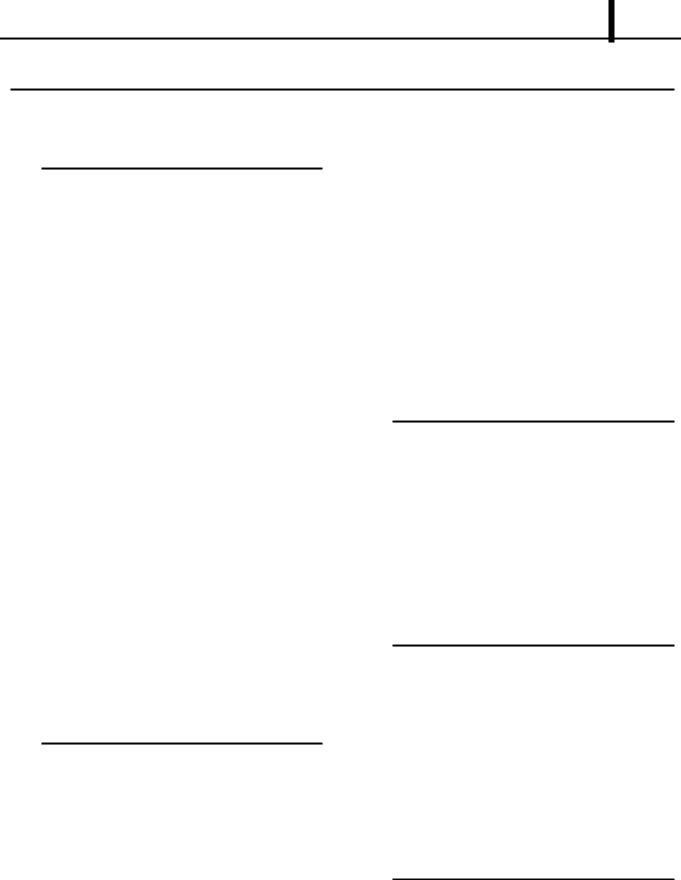
Table of Contents
Operation Section
1.PRODUCT APPILCATION INFORMATION
1.1 |
Application .................................................. |
1-1 |
1.2 |
System Components Part Number ............. |
1-1 |
2. |
OUTLINE OF SYSTEM |
|
2.1 |
Common Rail System Characteristics ........ |
1-2 |
2.2 |
Features of Injection Control....................... |
1-2 |
2.3 |
Comparison to the Conventional System.... |
1-3 |
2.4 |
Composition ................................................ |
1-3 |
2.5 |
Operation .................................................... |
1-4 |
2.6 |
Fuel System ................................................ |
1-4 |
2.7 |
Control System ........................................... |
1-4 |
3. |
SUPPLY PUMP |
|
3.1 |
Outline......................................................... |
1-6 |
3.2 |
Exterior View Diagram ................................ |
1-7 |
3.3 |
Supply Pump Internal Fuel Flow ................. |
1-7 |
3.4 |
Construction of Supply Pump ..................... |
1-8 |
3.5 |
Operation of the Supply Pump.................... |
1-9 |
4.SUPPLY PUMP COMPONENT PARTS
4.1 |
Feed Pump ................................................ |
1-11 |
4.2 |
SCV ( Suction Control Valve ) .................... |
1-11 |
4.3 |
Fuel Temperature Sensor ......................... |
1-13 |
5. |
RAIL |
|
5.1 |
Outline....................................................... |
1-14 |
6. RAIL COMPONENTS PARTS |
|
|
6.1 |
Rail Pressure Sensor (Pc Sensor) ............ |
1-15 |
6.2 |
Pressure limiter ......................................... |
1-15 |
7. |
INJECTOR (G2 TYPE) |
|
7.1 |
Outline....................................................... |
1-16 |
7.2 |
Characteristics .......................................... |
1-16 |
7.3 |
Exterior View Diagram .............................. |
1-17 |
7.4 |
Construction .............................................. |
1-18 |
7.5 |
Operation .................................................. |
1-18 |
7.6 |
QR Codes ................................................. |
1-19 |
7.7 |
Injector Actuation Circuit ........................... |
1-21 |
8.OPERATION OF CONTROL SYSTEM COMPONENTS
8.1 |
Engine Control System Diagram............... |
1-22 |
8.2 |
Engine ECU (Electronic Control Unit) ....... |
1-22 |
8.3 |
Cylinder Recognition Sensor (TDC).......... |
1-23 |
8.4 |
Turbo Pressure Sensor ............................. |
1-23 |
8.5 |
Mass Air Flow Sensor ............................... |
1-24 |
8.6 |
Electronic Control Throttle ........................ |
1-25 |
9. VARIOUS TYPES OF CONTROL
9.1 |
Outline....................................................... |
1-27 |
9.2 |
Fuel Injection Rate Control Function......... |
1-27 |
9.3 |
Fuel Injection Quantity Control Function ... |
1-27 |
9.4 |
Fuel Injection Timing Control Function...... |
1-27 |
9.5Fuel Injection Pressure Control Function (Rail
Pressure Control Function) ............. |
1-27 |
10.FUEL INJECTION QUANTITY CONTROL
10.1 |
Outline....................................................... |
1-28 |
10.2 |
Injection Quantity Calculation Method ...... |
1-28 |
10.3 |
Set Injection Quantities ............................. |
1-28 |

Table of Contents
11.FUEL INJECTION TIMING CONTROL
11.1 |
Ouline........................................................ |
1-32 |
11.2 |
Main and Pilot Injection Timing Control..... |
1-32 |
11.3 |
Microinjection Quantity Learning Control .. |
1-33 |
12.FUEL INJECTION RATE CONTROL
12.1 Outline....................................................... |
1-35 |
13.FUEL INJECTION PRESSURE CONTROL
13.1 Fuel Injection Pressure ............................. |
1-36 |
14.DIAGNOSTIC TROUBLE CODES (DTC)
14.1 |
About the Codes Shown in the Table........ |
1-37 |
14.2 |
Diagnostic Trouble Code Details............... |
1-37 |
15. EXTERNAL WIRING DIAGRAM
15.1 |
Engine ECU External Wiring Diagram ...... |
1-42 |
15.2 |
Engine ECU Connector Diagram .............. |
1-43 |

Operation Section
1 1
1.PRODUCT APPILCATION INFORMATION
1.1Application
|
|
Vehicle Manufac- |
Vehicle Name |
|
Engine Model |
|
Specification |
Destination (Vol- |
Line Off Period |
||
|
|
ture |
|
|
|
|
|
|
|
ume) |
|
|
|
|
|
|
|
|
|
|
|
|
|
|
|
|
|
|
4D56 |
|
|
2WD (MT/AT) |
|
|
|
|
|
MITSUBISHI |
TRITON |
|
|
|
|
|
Thailand |
June, 2005 |
|
|
|
|
|
|
|
4WD (MT) |
|||||
|
|
|
|
|
|
|
|
|
|
|
|
|
|
|
|
|
|
|
|
|
|
|
|
|
|
|
|
|
4M41 |
|
|
4WD (MT/AT) |
|
|
|
|
|
|
|
|
|
|
|
|
|
||
1.2 System Components Part Number |
|
|
|||||||||
|
|
|
|
|
|
|
|
|
|
|
|
|
|
Parts Name |
|
DENSO P/N |
|
Manufacturer P/N |
Remarks |
||||
|
|
|
|
|
|
||||||
|
Supply pump |
|
SM294000-0331 |
1460A001 |
For 4D56 Engine Model |
||||||
|
|
|
|
|
|
|
|||||
|
|
|
|
SM294000-0341 |
1460A003 |
For 4M41 Engine Model |
|||||
|
|
|
|
|
|
||||||
|
Injector |
|
SM095000-5600 |
1465A041 |
For 4D56 Engine Model |
||||||
|
|
|
|
|
|
|
|||||
|
|
|
|
SM095000-5760 |
1465A054 |
For 4M41 Engine Model |
|||||
|
|
|
|
|
|
|
|||||
|
Rail |
|
SM095440-0640 |
1465A034 |
ALL |
|
|||||
|
|
|
|
|
|
||||||
|
Engine ECU |
|
MA275800-425# |
1860A392 |
For 4D56 Engine Model (4WD) |
||||||
|
|
|
|
|
|
|
|||||
|
|
|
|
MA275800-431# |
1860A523 |
For 4D56 Engine Model (2WD MT) |
|||||
|
|
|
|
|
|
|
|||||
|
|
|
|
MA275800-432# |
1860A524 |
For 4D56 Engine Model (2WD AT) |
|||||
|
|
|
|
|
|
|
|||||
|
|
|
|
MA275800-357# |
1860A390 |
For 4M41 Engine Model (4WD) |
|||||
|
|
|
|
|
|
|
|
||||
|
Turbo pressure sensor |
|
079800-5960 |
|
MR577031 |
ALL |
|
||||
|
|
|
|
|
|
|
|||||
|
Cylinder recognition |
sensor |
949979-1590 |
|
1865A074 |
For 4M41 Engine Model |
|||||
|
(TDC) |
|
|
|
|
|
|
|
|
|
|
|
|
|
|
|
|
||||||
|
Electronic control throttle |
197920-0020 |
|
1450A033 |
For 4M41, 4D56 Engine Model (4WD) |
||||||
|
|
|
|
|
|
|
|||||
|
Fuel temperature sensor |
179730-0020 |
|
MR547077 |
ALL |
|
|||||
|
|
|
|
|
|
|
|||||
|
Mass air flow meter |
|
VN197400-4030 |
1460A001 |
ALL |
|
|||||
|
|
|
|
|
|
|
|
|
|
|
|
Operation Section
1 2
2.OUTLINE OF SYSTEM
2.1Common Rail System Characteristics
 The common rail system uses a type of accumulation chamber called a rail to store pressurized fuel, and injectors that contain electronically controlled solenoid valves to inject the pressurized fuel into the cylinders. Because the engine ECU controls the injection system (injection pressure, injection rate, and injection timing), the injection system is independent, and thus unaffected by the engine speed or load. This ensures a stable injection pressure at all times, particularly in the low engine speed range, and dramatically decreases the amount of black smoke ordinarily emitted by a diesel engine during start-up and acceleration. As a result, exhaust gas emissions are cleaner and reduced, and higher power output is achieved.
2.2 Features of Injection Control
(1)Injection Pressure Control
Enables high-pressure injection even at low engine speeds.
Optimizes control to minimize particulate matter and NOx emissions.
(2)Injection Timing Control
Enables finely tuned optimized control in accordance with driving conditions.
(3)Injection Rate Control
Pilot injection control injects a small amount of fuel before the main injection.
|
|
|
||||
|
|
|
|
|
||
|
|
|
|
|
|
|
|
|
|
|
|||
|
|
|
|
|
|
|
|
|
|
|
|
|
|
|
|
|
|
|
|
|
|
|
|
|
|
||
|
|
|
||||
|
|
|
||||
|
|
|
||||
|
|
|
||||
|
|
|
|
|
||
|
|
|
|
|
|
|
|
|
|
|
|||
|
|
|
|
|
|
|
|
|
|
|
|
|
|

|
|
Operation Section |
|
|
1 3 |
2.3 Comparison to the Conventional System |
||
In-line, VE Pump |
|
Common Rail System |
System |
|
|
|
|
|
|
|
|
|
|
|
|
|
|
|
|
|
|
|
|
|
|
|
|
|
|
|
|
|
|
|
|
|
|
|
|
|
|
|
|
|
||
|
|
|
|
Injection |
Pump (Governor) |
|
Engine ECU, Injector (TWV)*1 |
Quantity |
|
|
|
Control |
|
|
|
|
|
|
|
Injection |
Pump (Timer) |
|
Engine ECU, Injector (TWV)*1 |
Timing |
|
|
|
Control |
|
|
|
|
|
|
|
Rising |
Pump |
|
Engine ECU, Supply Pump |
Pressure |
|
|
|
|
|
|
|
Distributor |
Pump |
|
Engine ECU, Rail |
|
|
|
|
Injection |
Dependent upon Speed and Injection Quantity |
Engine ECU, Supply Pump (SCV)*2 |
|
Pressure |
|
|
|
Control |
|
|
|
< NOTE >
*1 : TWV: Two Way Valve
*2 : SCV: Suction Control Valve
2.4 Composition
 The common rail system consists primarily of a supply pump, rail, injectors, and engine ECU.

Operation Section
1 4


|
|
|
|
|
|
|
|
|
|
|
|
|
|
|
|
|
|
|
|
|
|
|
|
|
|
|
|
|
|
|
|
|
|
||
|
|
||
|
|
|
|
2.5 Operation
(1)Supply Pump (HP3)
The supply pump draws fuel from the fuel tank, and pumps the high pressure fuel to the rail. The quantity of fuel discharged from the supply pump controls the pressure in the rail. The SCV (Suction Control Valve) in the supply pump effects this control in accordance with commands received from the engine ECU.
(2)Rail
The rail is mounted between the supply pump and the injector, and stores the high-pressure fuel.
(3)Injector (G2 type)
This injector replaces the conventional injection nozzle, and achieves optimal injection by effecting control in accordance with signals from the engine ECU. Signals from the engine ECU determine the duration and timing in which current is applied the injector. This in turn, determines the quantity, rate and timing of the fuel that is injected from the injector.
(4)Engine ECU
The engine ECU calculates data received from the sensors to comprehensively control the injection quantity, timing and pressure, as well as the EGR (exhaust gas recirculation).
2.6 Fuel System
 This system comprises the route through which diesel fuel flows from the fuel tank via the rail to the supply pump, and is injected through the injector, as well as the route through which the fuel returns to the tank via the overflow pipe.
2.7 Control System
 In this system, the engine ECU controls the fuel injection system in accordance with signals received from various sensors. The components of this system can be broadly divided into the following three types: (1) sensors; (2) ECU; and (3) actuators.

Operation Section
1 5
(1)Sensors
Detect the engine and driving conditions, and convert them into electrical signals.
(2)Engine ECU
Performs calculations based on the electrical signals received from the sensors, and sends them to the actuators in order to achieve optimal conditions.
(3)Actuators
Operate in accordance with electrical signals received from the ECU. Injection system control is undertaken by electronically controlling the actuators. The injection quantity and timing are determined by controlling the duration and timing in which current is applied to the TWV (Two-Way Valve) in the injector. Injection pressure is determined by controlling the SCV (Suction Control Valve) in the supply pump.
|
|
|
|
|
|
||
|
|
|
|
|
|
||
|
|
|
|
|
|
||
|
|
|
|
|
|
|
|
|
|
|
|
|
|
|
|
|
|
|
|
|
|
||
|
|
|
|
|
|
||
|
|
|
|
|
|
|
|
|
|
|
|
|
|
||
|
|
|
|
||||
|
|
|
|
|
|||
|
|
|
|
|
|||
|
|
|
|
|
|
||
|
|
|
|
|
|
||
|
|
|
|
|
|
||
|
|
|
|
|
|
||
|
|
|
|
|
|
|
|
|
|
|
|||||
|
|
|
|
|
|
|
|
|
|
|
|
|
|
|
|
|
|
|
|
|
|
|
|
|
|
|
|
|
|
|
|
|
|
|
|
|
|
|
|
|
|
|
|
|
|
|
|
|
|
|
|
|
|
|
|
|
|
|
|
|
|
||
|
|
|
|
|
|||
|
|
|
|
|
|
||
|
|
|
|
|
|
|
|
|
|
|
|
|
|
|
|
Operation Section
1 6
3. SUPPLY PUMP
3.1 Outline
 The supply pump consists primarily of the pump body (eccentric cam, ring cam, and plungers), SCV (Suction Control Valve), fuel temperature sensor, and feed pump.
 The two plungers are positioned vertically on the outer ring cam for compactness.
 The engine drives the supply pump at a ratio of 1:1. The supply pump has a built-in feed pump (trochoid type), and draws the fuel from the fuel tank, sending it to the plunger chamber.
 The internal camshaft drives the two plungers, and they pressurize the fuel sent to the plunger chamber and send it to the rail. The quantity of fuel supplied to the rail is controlled by the SCV, using signals from the engine ECU. The SCV is a normally open type (the intake valve opened during de-energization).
|
|
|
|
|
|
|
|
|
|
|
|
|
|
|
|
|
|
|
|
|
|
|
|
|
|
|
|
|
|
|
|
|
|
|
|
|
|
|
|
|
|
|
|
Operation Section
1 7
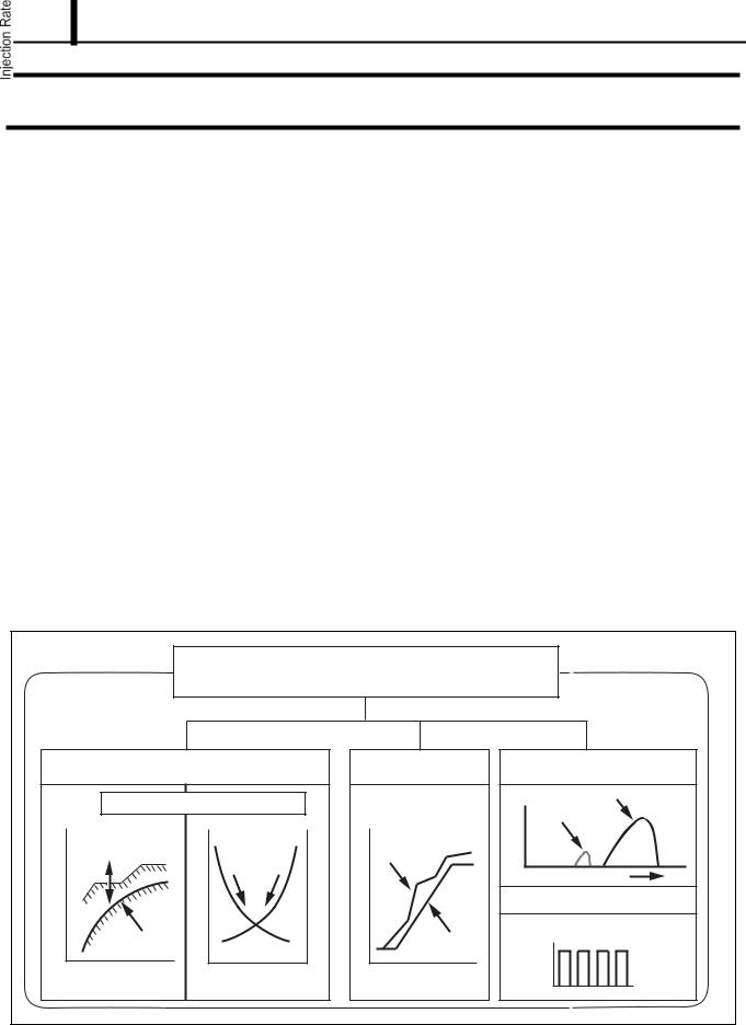
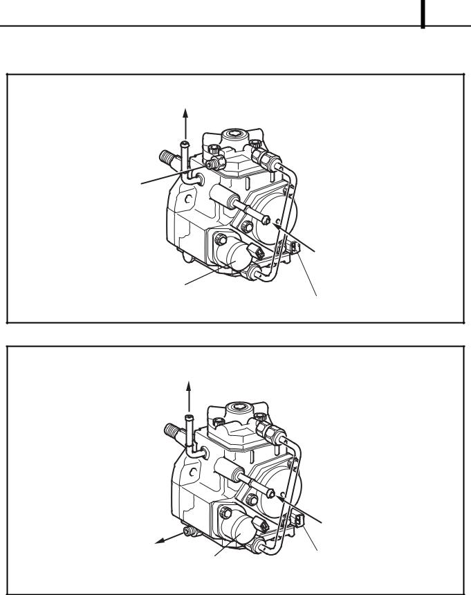
3.2 Exterior View Diagram
4D56 Engine Model

4M41 Engine Model
3.3 Supply Pump Internal Fuel Flow
 The fuel that is drawn from the fuel tank passes through the route in the supply pump as illustrated, and is fed into the rail.
Operation Section
1 8
|
|
|
|
|
|
|
|
|
|
|
|
|
|
|
|
|
|
|
|
|
|
|
||
|
|
|
|
|
|
|
|
|
|
|
|
|
|
|
|
|
|
|
|
|
|
|||
|
|
|
|
|
|
|
|
|
|
|
|
|
|
|
|
|
|
|
|
|
|
|
|
|
|
|
|
|
|
|
|
|
|
|
|
|
|
|
|
|
|
|
|
|
|
||||
|
|
|
|
|
|
|
|
|
|
|
|
|
|
|
||||||||||
|
|
|
|
|
|
|
|
|
|
|
|
|
|
|
|
|
|
|
|
|
|
|
|
|
|
|
|
|
|
|
|
|
|
|
|
|
|
|
|
|
|
||||||||
|
|
|
|
|
|
|
|
|
|
|
|
|||||||||||||
|
|
|
|
|
|
|
|
|
|
|
|
|
|
|
|
|
|
|
|
|
||||
|
|
|
|
|
|
|
|
|
|
|
|
|
|
|||||||||||
|
|
|
|
|
|
|
|
|
|
|
|
|
|
|
|
|
|
|||||||
|
|
|
|
|
|
|
|
|
|
|
|
|
|
|
|
|
|
|
|
|
|
|
|
|
|
|
|
|
|
|
|
|
|
|
|
|
|
|
|
|
|
|
|
|
|
|
|
|
|
3.4 Construction of Supply Pump
 The eccentric cam is attached to the drive shaft. The eccentric cam is connected to the ring cam.
 As the drive shaft rotates, the eccentric cam rotates eccentrically, and the ring cam moves up and down while rotating.

 The plunger and the suction valve are attached to the ring cam. The feed pump is connected to the rear of the drive shaft.
Operation Section
1 9
|
|
|
3.5 Operation of the Supply Pump
 As shown in the illustration below, the rotation of the eccentric cam causes the ring cam to push Plunger A upwards. Due to the spring force, Plunger B is pulled in the opposite direction to Plunger A. As a result, Plunger B draws in fuel, while Plunger A pumps it to the rail.

Operation Section
1 10
|
|


|
|
|
|
|
|
|
|
|
|
|
|
|
|
|
|
|
|
|
|
|
|
|
|
|
|
|
|
|
|
|
|
|
|
|
|
|
|
|
|
|
|
|
|
|
|
|
|
|
|
|
|
|
|
|
|
|
|
|
|
|
|
|
|
|
|
|
|
|
|
|
|
|
|
|
|
|
|
|
|
|
|
|
|
|
|
|
|
|
|
|
|
|
|
|
|
|
|
|
|
|
|
|
|
|
|
|
|
|
|
|
|
|
|
|
|
|
|
|
|
|
|
|
|
|
|
|
|
|
|
|
|
|
|
|
|
|
|
|
|
|
|
|
|
|
|
|
|
|
|
|
|
|
|
|
|
|
|
|
|
|
|
|
|
|
|
|
|
|
|
|
|
|
|
|
|
|
|
|
|
|
|
|
|
|
|
|
|
|
|
|
|
|
|
|
|
|
|
|
|
|
|
|
|
|
|
|
|
|
|
|
|
|
|
|
|
|
|
|
|
|
|
|
|
|
|
|
|
|
|
|
|
|
|
|
|
|
|
|
|
|
|
|
|
|
|
|
|
|
|
|
|
|
|
|
|
|
|
|
|
|
|
|
|
|
|
|
|
|
|
|
|
|
|
|
|
|
|
|
|
|
|
|
|
|
|
|
|
|
||||||||||||||||||||||||
|
|
|
|
||||||||||||||||||||||||

Operation Section
1 11
4. SUPPLY PUMP COMPONENT PARTS
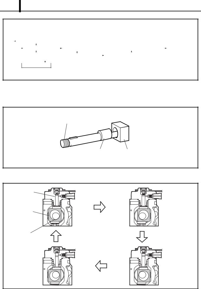
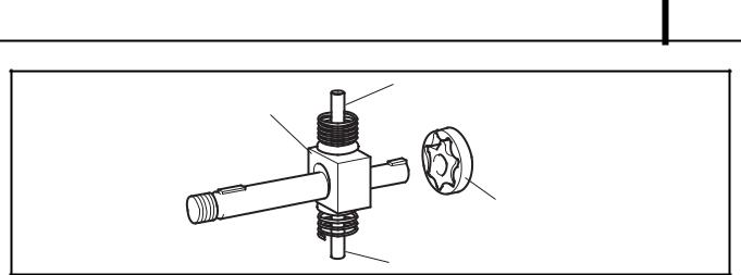
4.1 Feed Pump
 The trochoid type feed pump, which is integrated in the supply pump, draws fuel from the fuel tank and feeds it to the two plungers via the fuel filter and the SCV (Suction Control Valve). The feed pump is driven by the drive shaft. With the rotation of the inner rotor, the feed pump draws fuel from its suction port and pumps it out through the discharge port. This is done in accordance with the space that increases and decreases with the movement of the outer and inner rotors.
|
|
|
|
|
|
|
|
|
|
|
|
|
|
|
|
|
|
|
|
|
|
|
|
|
|||
|
|
|
|
4.2 SCV ( Suction Control Valve )
 A linear solenoid type valve has been adopted. The ECU controls the duty ratio (the duration in which current is applied to the SCV), in order to control the quantity of fuel that is supplied to the high-pressure plunger.
 Because only the quantity of fuel that is required for achieving the target rail pressure is drawn in, the actuating load of the supply pump decreases.
 When current flows to the SCV, variable electromotive force is created in accordance with the duty ratio, moving the cylinder (integrated with the armature) to the left side, and changing the opening of the fuel passage to regulate the fuel quantity.
 With the SCV OFF, the return spring contracts, completely opening the fuel passage and supplying fuel to the plungers. (Full quantity intake and full quantity discharge = normally open)
 When the SCV is ON, the force of the return spring moves the cylinder to the left, closing the fuel passage (normally open).
 By turning the SCV ON/OFF, fuel is supplied in an amount corresponding to the actuation duty ratio, and fuel is discharged by the plungers.
 Loading...