


00-1
GROUP 00
CONTENTS
HOW TO USE THIS MANUAL. . . . . . |
00-2 |
TARGETS OF DEVELOPMENT . . . . |
00-2 |
PRODUCT FEATURES . . . . . . . . . . . |
00-2 |
TECHNICAL FEATURES. . . . . . . . . . |
00-3 |
EXTERIOR . . . . . . . . . . . . . . . . . . . . . . . . . |
00-3 |
INTERIOR . . . . . . . . . . . . . . . . . . . . . . . . . . |
00-4 |
SPACIOUS CABIN . . . . . . . . . . . . . . . . . . . |
00-4 |
ENGINE . . . . . . . . . . . . . . . . . . . . . . . . . . . |
00-5 |
TRANSMISSION. . . . . . . . . . . . . . . . . . . . . |
00-5 |
SUSPENSION. . . . . . . . . . . . . . . . . . . . . . . |
00-8 |
BRAKE . . . . . . . . . . . . . . . . . . . . . . . . . . . . |
00-10 |
STEERING . . . . . . . . . . . . . . . . . . . . . . . . . |
00-11 |
LOCAL INTERCONNECT NETWORK (LIN) |
00-12 |
. . . . . . . . . . . . . . . . . . . . . . . . . . . . . . . . . . . . . . |
|
ACTIVE SAFETY. . . . . . . . . . . . . . . . . . . . . |
00-13 |
PASSIVE SAFETY . . . . . . . . . . . . . . . . . . . |
00-17 |
EQUIPMENTS . . . . . . . . . . . . . . . . . . . . . . . |
00-20 |
ENVIRONMENTAL PROTECTION . . . . . . . |
00-21 |
SERVICEABILITY AND RELIABILITY . . . . |
00-21 |
VEHICLE IDENTIFICATION . . . . . . . . |
00-22 |
MAJOR SPECIFICATIONS . . . . . . . . |
00-23 |
00-2 |
GENERAL |
HOW TO USE THIS MANUAL |
HOW TO USE THIS MANUAL
MODEL INDICATIONS
The following abbreviations are used in this manual for identification of model types.
1100: Indicates models equipped with the 1,124 mL <134910> petrol engine.
1300: Indicates models equipped with the 1,332 mL <135930> petrol engine.
M2000029000242
1500: Indicates models equipped with the 1,499 mL <13590> petrol engine.
DOHC: Indicates an engine with the double overhead camshaft.
MIVEC: Indicates Mitsubishi innovative valve timing electronic control system.
MPI: Indicates the multipoint injection. M/T: Indicates the manual transmission. A/C: Indicates the air conditioner.
TARGETS OF DEVELOPMENT
M2000004000342
COLT has been developed as entry model of Mitsubishi model line-up, as compact passenger car with space MPV versatility.
PRODUCT FEATURES
ADVANCED AND FASHIONABLE STYLING
The one motion silhouette which consists of roominess and stylish appearance.
NEWLY DEVELOPED ENGINE WITH GOOD FUEL EFFICIENCY AND EXCELLENT POWER-DRIVEN PERFORMANCE
•134910-DOHC MIVEC* engine with 3-cylinder
•135930-DOHC MIVEC engine and
135950-DOHC MIVEC engine with 4-cylinder
NOTE: *MIVEC: Mitsubishi Innovative Valve timing Electronic Control system is a generic term for the engine with variable valve timing mechanism.
M2000005000174
HIGH LEVEL OF SAFETY
•Reinforced Impact Safety Evolution (RISE) chassis adopted
•Driver's SRS airbag equipped as standard
•Front passenger's SRS airbag, SRS side airbag, and SRS curtain airbag adopted <Optional>
•ISO FIX child seat fixing bar equipped as standard
EXCELLENT PRACTICABILITY AND SPACE UTILITY
•Multi function box storage as cup holder, ashtray, small item holder, etc.
•6:4 separate sliding, tumbling and removable rear seat.

GENERAL |
00-3 |
TECHNICAL FEATURES |
TECHNICAL FEATURES
EXTERIOR
M2000017000331
DESIGN FEATURES
1
2
5
 3
3
 4
4
OVERALL
•Dynamic one motion line connects chamfered front end.
•Simple body side section emphasis the wheel arches.
•Dynamic DLO (day light opening) creates car is motion even when car is stop.
•Front lights on the chamfered surface follows one of the Mitsubishi identity.
•Inside of the light reflectors given high-tech image of Japanese product.
•Simple exterior design emprises car’s functionality.
•Door cut’s matching the lines of the DLO and rear light.
1
6
AC311182AC
1. SIDE SILHOUETTE
Simple and dynamic one motion curve from the front nose to the roof end.
2. BODY SIDE SURFACE
Take simple and clean surface to emphasize wheel arches.
3. MITSUBISHI MARK
New Mitsubishi front face which designed every elements connects from three diamonds.
4. FRONT END CORNER
Apply the chamfer shape for easy handling.
5. HEAD LAMP
Create the high-tech image of Japanese product.

00-4 |
GENERAL |
TECHNICAL FEATURES |
|
6. TAIL LAMP |
INTERIOR |
Apply long vertical type to easy to recognize from outside.
M2000018000312
DESIGN FEATURES
Combination meter |
Instrument panel |
|
Translucent |
|
parts |
|
AC312521AB |
Cup holder and ashtray |
Glove box |
OVERALL
• Sporty elegance feeling with comfortable space.
• The maximum roominess in the limited package.
INSTRUMENT PANEL
• Illumination systems presented by translucent parts of audio and A/C control panel
• Searchlight system from translucent parts.
• Useful glove box (card holder, pen holder, coin holders and bottle holder).
By the adoption of the long wheelbase, it realizes the interior length of the top-class.

GENERAL |
00-5 |
TECHNICAL FEATURES |
4 5
|
|
1 |
|
2 |
|
|
|
|
3 |
|
|
|
|
|
|
|
AC311954AB |
No. |
Item |
Dimension mm |
No. |
Item |
Dimension mm |
1 |
Brake pedal room |
880 |
4 |
Front head room |
931 |
2 |
Hip point couple |
825 |
5 |
Rear head room |
862 |
3 |
Total leg room |
1,705 |
|
|
|
NOTE: Refer to P.00-23 for the body dimensions.
ENGINE
M2000020000223
The following three types of newly developed engines have been adopted to realize light weight, small size, and good fuel efficiency. Those engines are complied with Step 4 in European emissions regulations.
Item |
|
134910 |
135930 |
135950 |
|
Total displacement mL |
1,124 |
1,332 |
1,499 |
||
|
|
|
|
||
Bore × stroke mm |
75 × 84.8 |
75 × 75.4 |
75 × 84.8 |
||
|
|
|
|
||
Compression ratio |
10.5 |
|
|
||
|
|
|
|
||
Combustion chamber |
Pentroof-type |
|
|
||
|
|
|
|
|
|
Valve |
Intake opening |
BTDC 41° − ATDC 9° |
BTDC 41° − ATDC 9° |
BTDC 41° − ATDC 9° |
|
timing |
|
|
|
|
|
Intake closing |
ABDC 19° − ABDC 69° |
ABDC 3° − ABDC 53° |
ABDC 11° − ABDC 61° |
||
|
|||||
|
|
|
|
|
|
|
Exhaust opening |
BBDC 35° |
BBDC 35° |
BBDC 39° |
|
|
|
|
|
|
|
|
Exhaust closing |
ATDC 5° |
ATDC 5° |
ATDC 5° |
|
|
|
|
|
|
|
Maximum |
output kW(PS)/rpm |
55(75)/6,000 |
70(95)/6,000 |
80(109)/6,000 |
|
|
|
|
|
||
Maximum torque |
100(10.2)/3,500 |
125(12.7)/4,000 |
145(14.8)/4,000 |
||
N m(kg-m)/rpm |
|
|
|
||
|
|
|
|
|
|
TRANSMISSION
M2000021000226
The following two types of newly developed transmissions with light weight and small-size design have been adopted to realize good fuel efficiency.
•F5MGA 5-speed manual transmission
•F6SGA 6-speed automated manual transmission

00-6 |
GENERAL |
TECHNICAL FEATURES |
MANUAL TRANSMISSION
SECTIONAL VIEW
5th gear |
2nd gear |
Reverse gear |
1st gear |
Input shaft
Output shaft
4th gear
3rd gear
Differential
AC311790 AC

GENERAL |
00-7 |
TECHNICAL FEATURES |
AUTOMATED MANUAL TRANSMISSION
OUTSIDE VIEW
Shift actuator assembly
Drum position sensor
Clutch actuator 
AC311791AB
As automated manual transmission is designed |
SCHEMATIC DIAGRAM |
||
based on 6-speed manual gearbox and driven by |
|
||
electric actuators (motors) via sophisticated |
|
||
twin-drum shift mechanism, it gives our customers |
|
||
"easy to drive as A/T", "fun to drive and high fuel effi- |
|
||
ciency as M/T". |
|
||
Shift actuator Automated manual transmission |
Clutch actuator |
||
assembly |
|
||
|
|
|
|
|
|
|
|
Engine
Engine automated manual transmission electronic control unit (Engine-A-M/T-ECU)
Accelerator pedal |
N |
Allshift lever |
A |
||
Brake pedal |
|
|
R |
AC311704AB |
DRIVING MODE
Driving mode provides either manual mode (like sequential M/T) or automatic mode (like conventional A/T), by tipping shift lever toward "A" or "+" or "−" from "s.b." position.

00-8 |
GENERAL |
TECHNICAL FEATURES |
+: Up shifting
s.b.: Stand by (manual selection of gear) : Down shifting
A: Switch automatic manual mode
N: Neutral
R: Reverse gear
 : Automatic resume
 : Manual operation
|
|
|
AC312516AB |
|
|
|
|
Position |
Operation |
Function |
Further explanation |
"N" |
In "N" |
Neutral |
Engine start possible only at "N". |
|
|
|
|
"R" |
"N" → "R" |
Reverse drive |
No creeping. |
|
|
|
|
s.b. (stand |
"N" → s.b. |
Forward drive |
Creeping starts (with brake pedal depress). |
by) |
|
|
|
|
Auto mode or Manual |
Starts from auto mode. <135950> |
|
|
|
mode |
|
|
|
Starts from manual mode. <135930> |
|
|
|
|
|
|
|
|
|
"A" |
s.b. → "A" |
Mode change |
Auto mode or Manual mode comes alternatively. |
|
(tip) |
|
(Auto mode → Manual mode → Auto mode → Manual |
|
|
|
mode) |
|
|
|
|
"+", "−" |
s.b. → "+" |
+: Manual up shifting |
Higher gear will be selected. *1, *2 |
|
(tip) |
|
|
|
−: Manual down shifting |
Lower gear will be selected. *1, *3 |
|
|
s.b. → "−" |
||
|
|
|
|
|
*1: After "+" or "−" tip action, mode becomes manual mode. |
||
|
(tip) |
||
|
|
*2: If vehicle speed is too low, some up shifts neglected. |
|
|
|
*3: If engine speed is too high, down shifting neglected. |
|
|
|
|
|
SUSPENSION
M2000023000211
FRONT SUSPENSION
The newly developed MacPherson Strut suspension with compatible characteristics of high rigidity and light weight has been adopted for the front suspension to realize sufficient driving comfort and driving stability.

GENERAL |
00-9 |
TECHNICAL FEATURES |
Strut assembly
Coil spring
Stabilizer bar
Lower arm
Crossmember
AC310151AB
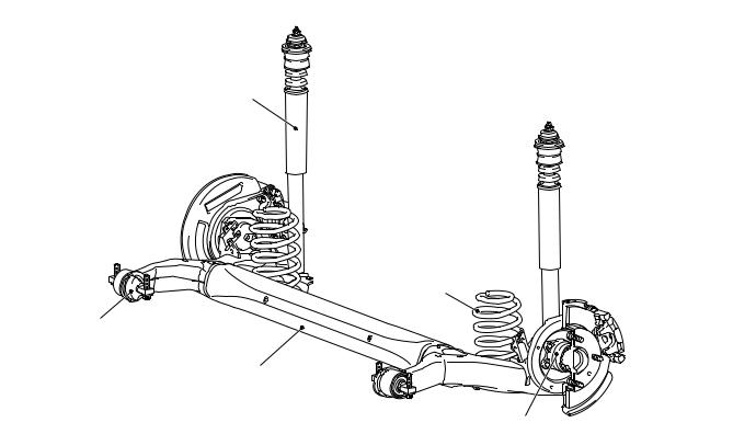
REAR SUSPENSION
The torsion beam suspension has been adopted for the rear suspension to realize a large suspension stroke and excellent driving comfort. The suspension with small-size design has provided ample interior space.
00-10 |
GENERAL |
TECHNICAL FEATURES |
Shock absorber
Coil spring
Arm bushing
Torsion beam and arm assembly
Unit type bearing |
AC310152AB |
BRAKE
M2000024000043
14-inch ventilated disk brake for the front, 8-inch leading trailing drum brake or 14-inch solid disk brake for the rear have been installed to realize high reliability and durability along with excellent braking performance.
GENERAL |
00-11 |
TECHNICAL FEATURES |
<Vehicle with rear drum brake>
Brake booster
Hydraulic unit
(Integrated with ABS-ECU/Active Stability Control System-ECU)
Rear drum brake
Master cylinder
Parking brake lever
Front disc brake |
AC311564 |
<Vehicle with rear disc brake>
Brake booster
Hydraulic unit
(Integrated with ABS-ECU/Active Stability Control System-ECU)
Master cylinder |
Rear disc brake |
|
Parking brake lever |
||
|
||
Front disc brake |
AC311651 |
|
|
AC311650AB |
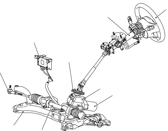
STEERING
M2000040000010
Due to the adoption of electric power steering driven by newly developed pinion shaft, effortless steering wheel manoeuvring at the low speed as well as stable steering wheel manoeuvring at the mid to high speed has been achieved.
00-12 |
GENERAL |
TECHNICAL FEATURES |
Steering wheel
Steering column assembly
Electric power steering-ECU
Dash panel cover
Tie rod end
Torque sensor
Motor
Crossmember
Steering gear |
AC310150AB |
LOCAL INTERCONNECT NETWORK (LIN)
M2000041000013
LIN refers to "Local Interconnect Network", a global
standard of serial multiplex communication protocol*1 administrated by LIN consortium. A communication circuit employing the LIN protocol connects each ECU, and switch data can be shared among ECUs, which enables more reduction in wiring. Transmission speed is 19.2 kbps.
For COLT, ETACS*2-ECU can receive some input
NOTE: *1: The regulations have been decided in detail, from software matters such as the necessary transmission rate for communication, the system, data format, and communication timing control method to hardware matters such as the harness type and length and the resistance values.
NOTE: *2: ETACS (Electronic Time and Alarm Control System)
NOTE: *3: CAN (Controller Area Network)
signals through CAN*3 communication in addition to the LIN communication.

GENERAL |
00-13 |
TECHNICAL FEATURES |
ACTIVE SAFETY
M2000031000216
BRAKING SYSTEM
ABS warning lamp
Brake warning lamp
AC311642
Hydraulic unit and
ABS-ECU
Diagnosis connector
Stop lamp switch |
Wheel speed sensor |
|
Wheel speed sensor |
AC311643 |
|
AC311644AC |
00-14 |
GENERAL |
TECHNICAL FEATURES |
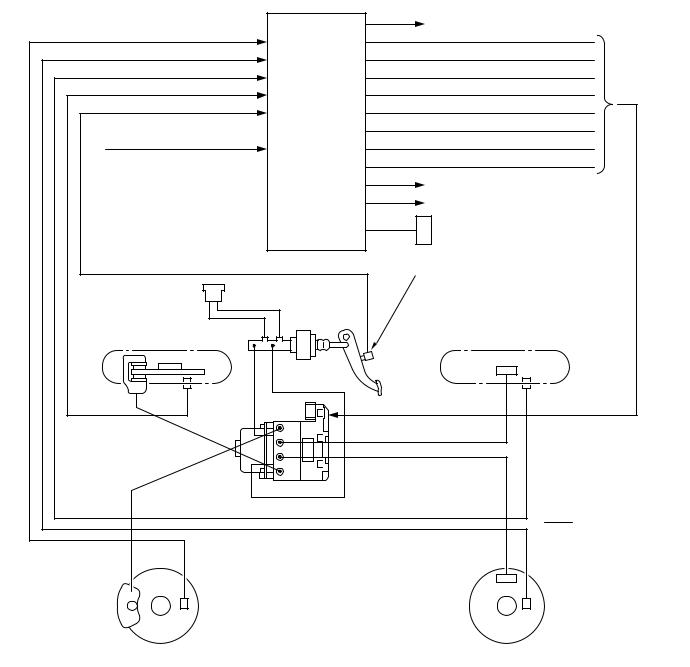
|
|
Engine-ECU <M/T> or Engine-A-M/T-ECU* |
|
Front-left wheel speed sensor |
|
<Automated manual transmission> |
|
|
Front right solenoid valve (out) |
||
Rear-left wheel speed sensor |
|
Front right solenoid valve (in) |
|
Rear-right wheel speed sensor |
|
Front left solenoid valve (out) |
|
Front-right wheel speed sensor |
|
Front left solenoid valve (in) |
|
Stop lamp switch |
|
Rear right solenoid valve (out) |
|
|
ABS-ECU |
Rear right solenoid valve (in) |
|
ABS-ECU power supply |
Rear left solenoid valve (out) |
||
|
|||
|
|
Rear left solenoid valve (in) |
|
|
|
Brake warning lamp |
|
|
|
ABS warning lamp |
|
|
|
Diagnosis connector |
|
|
|
Stop lamp switch |
Front-right wheel (FR) |
Rear-right wheel (RR) |
Front-right |
Rear-right wheel |
|
wheel |
speed sensor |
|
speed |
||
sensor |
Note |
|
|
||
|
*Engine-A-M/T-ECU: |
|
Hydraulic |
Engine automated manual |
|
transmission electronic |
||
unit (HU) |
||
|
control unit |
|
|
: CAN-bus line |
Front-left wheel |
Rear-left wheel |
speed sensor |
speed sensor |
Front-left wheel (FL) |
Rear-left wheel (RL) |
AC311645AC
4-WHEEL ANTI-SKID BRAKING SYSTEM (4ABS)
A 4-wheel anti-skid braking system (4ABS) has been adopted to prevent slipping caused by the vehicle wheels locking up, in order to minimize braking distance, and also to maintain a stable vehicle posture and steering performance.
ELECTRONIC BRAKE-FORCE DISTRIBUTION (EBD)
An electronic brake-force distribution (EBD) which makes it possible to maintain the maximum amount of braking force even when the vehicle's load is varied has been adopted.

GENERAL |
00-15 |
TECHNICAL FEATURES |
ANTI-SKID BRAKE SYSTEM (ABS)/ACTIVE STABILITY CONTROL SYSTEM
Anti-skid Brake/Active stability control indicator lamp
Steering wheel sensor
Pressure sensor, Hydraulic unit and Anti-skid Brake/Active stability control system control unit (ABS/Active stability control system-ECU)
Diagnosis connector
Engine-ECU <M/T> or Engine-A-M/T-ECU (Engine automated manual transmission electronic control unit)
<Automated manual transmission>
G and yaw rate sensor
Wheel speed sensor
Stop lamp switch
Wheel speed sensor |
AC311649AC |
00-16 |
GENERAL |
TECHNICAL FEATURES |
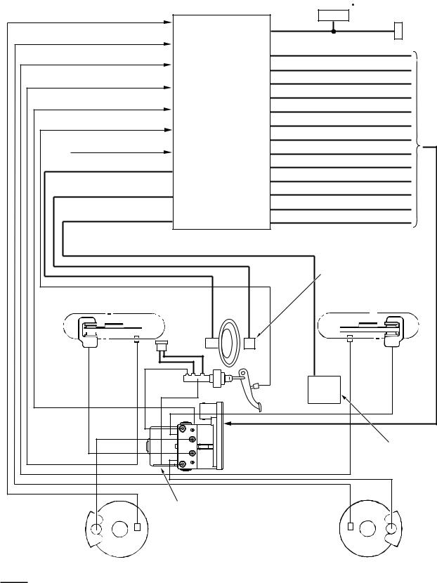
Front-left wheel speed sensor
Rear-left wheel speed sensor
Rear-right wheel speed sensor
Front-right wheel speed sensor
Master cylinder pressure sensor
Stop lamp switch
Power supply to ABS/Active stability control system-ECU
Steering wheel sensor
G and yaw rate sensor
Engine-ECU <M/T> or engine-A- M/T-ECU <Automated manual transmission>
ABS/Active stability control system-ECU
Combination meter ABS/Active stability control indicator lamp
Diagnosis
Connector
Suction valve (FR)
Suction valve (FL)
Cut valve (FR)
Cut valve (FL)
Control solenoid valve (FR) IN
Control solenoid valve (FR) OUT
Control solenoid valve (FL) IN
Control solenoid valve (FL) OUT
Control solenoid valve (RR) IN
Control solenoid valve (RR) OUT
Control solenoid valve (RL) IN
Control solenoid valve (RL) OUT
Pamp motor
G and yaw rate sensor
Front-right wheel (FR) |
Rear-right wheel (RR) |
||
|
|
|
|
|
Steering |
|
Wheel |
wheel |
Wheel |
sensor |
||
speed |
|
speed |
sensor |
|
sensor |
|
|
Stop lamp |
|
|
switch |
|
|
Engine-ECU <M/T> or engine- |
|
|
A-M/T-ECU <Automated manual |
|
|
transmission> |
|
Hydraulic |
|
|
unit |
Wheel speed |
|
Wheel speed |
|
|
sensor |
sensor |
Front-left wheel (FL)
Rear-left wheel (RL)
Note
: CAN-bus line |
AC311782AC |

GENERAL |
00-17 |
TECHNICAL FEATURES |
The Anti-skid Brake System (ABS)/Active stability control system is a combination system of active stability control system and anti-skid brake control system. The active stability control system avoids a dangerous vehicle attitude by limiting the engine output and braking a set of wheels (left front and right rear, or right front and left rear) according to driving conditions. The anti-skid brake control system prevents wheel spinning at vehicle start.
ABS/Active stability control system is available for all models as optional equipment.
PASSENGER’S AIR BAG CUT OFF SWITCH
AC311721
AC311720
AC312760 AB
Passenger’s air bag cut off switch is located in the glove box.
The passenger’s air bag cut off switch can be used to disable the passenger's (front) air bag.
PASSIVE SAFETY
M2000032000208
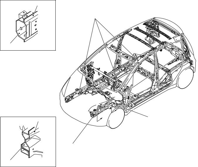
IMPACT SAFETY BODY
The front and rear structures to absorb high energy, and the highly tough cabin structure reduce the risk of passenger injuries at front-, rear-, and side-impact collisions, secure the space for life protection, and facilitate rescuing passengers.
00-18 |
GENERAL |
TECHNICAL FEATURES |
Section A - A Front side member outer
Front side member
inner |
AB301790 |
Section B - B Front side member outer
1
2
 B
B 

A


AB301783
B
1
A
Front side member |
|
|
inner |
AB301791 |
AB301835AB |
1.The octagonal cross section for the front of the front sidemember and 8-shaped cross section for the rear of the front sidemember have been adopted for enlargement so that the applied structures can effectively absorb energy from the impact at the time of collision.
2.Due to the adoption of straightened front sidemember and the rear floor sidemember, the structure can effectively absorb energy from the impact at the time of collision.

GENERAL |
00-19 |
TECHNICAL FEATURES |
SUPPLEMENTAL RESTRAINT SYSTEM (SRS) AND FRONT SEAT BELTS WITH PRE-TENSIONER
Driver's air bag |
Curtain air bag modules |
|
module |
Passenger's (front) |
|
Seat belt with |
||
air bag module |
||
pre-tensioner |
|
Side air bag modules
SUPPLEMENTAL RESTRAINT SYSTEM (SRS)
The SRS is designed to supplement the front seat belts. It eliminates or reduces injury to the front passenger(s) by deploying air bag(s) in case of a head-on collision.
AC313299AB
SEAT BELT WITH PRE-TENSIONER
The seat belts with pre-tensioner work simultaneously with the SRS. The pre-tensioner takes up seat belt slack immediately when a collision takes place, restraining the front passengers sooner than the SRS. This prevents the passengers from moving forward.
SRS SIDE AIR BAG
Side air bag systems in the front seats are activated when sideward impacts applied to the vehicle exceed a threshold to protect the occupants’ upper bodies.
SRS CURTAIN AIR BAG
The curtain air bag systems are activated when sideward impacts applied to the vehicle exceed a threshold, to protect the heads of the occupants in the front and rear seats.
STEERING SHAFT AND STEERING COLUMN
The impact absorption mechanism in combination of retractable steering shaft and steering column disengagement mechanism has been adopted to alleviate the impact from the steering wheel to the driver.
BRAKE PEDAL
The brake pedal backward movement restraint mechanism to restrain the backward movement of the brake pedal to the minimum at the time of frontal collision has been adopted so that the impact to the lower limbs of the driver can be alleviated.
00-20 |
GENERAL |
TECHNICAL FEATURES |
CHILD SEAT FIXING BAR COMPATIBLE WITH ISO FIX*
The anchor bar has been equipped as standard for easily and securely fixing the child seat compatible with ISO FIX.
NOTE: *ISO: International Organisation for Standardisation
REAR SEAT BELT WITH CHILD SEAT FIXING MECHANISM (ALR*)
The child seat fixing mechanism has been adopted to easily and securely fix the child seat that is not compatible with ISO FIX.
NOTE: *ALR: Automatic Locking Retractor
POWER WINDOW WITH SAFETY MECHANISM
The power window with safety mechanism has been adopted to automatically roll down and stop the door window glass as soon as the occurrence of jamming is detected at the time of rolling up the door window glass.
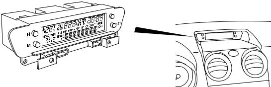
Multi-centre display
The multi-centre display to provide vehicle information in the text form has been equipped on the centre console as standard. The multi-centre display has the following functions:
• Clock
SUNROOF WITH SAFETY MECHANISM
The sunroof with safety mechanism has been adopted so that the roof lid glass can move in the reverse direction and stop when application of external force hinders the movement during the sliding to close or tilt down operation.
TRIMS AND HEADLINING
The head impact absorption structure has been adopted for the pillar trim, quarter trim, and headlining so that impact towards the head of a passenger can be reduced.
OTHER SAFETY FEATURES
•3-point ELR seat belts
•Child-protection rear door locks
•Front fog lamps <Optional>
•Rear fog lamp (Driver’s side)
EQUIPMENTS
M2000026000191
MULTI-CENTRE DISPLAY
AC311613 AB
•Outside temperature
•Vehicle information (average speed, instant fuel consumption, remaining distance)
•Audio information
|
|
GENERAL |
00-21 |
|
|
TECHNICAL FEATURES |
|
IMMOBILIZER SYSTEM |
|
|
|
Ignition key |
Key ring antenna |
ETACS-ECU |
Engine-ECU <M/T> or Engine-A-M/T-ECU* |
|
|
(immobilizer-ECU) |
<Automated manual transmission> |
|
|
|
Power |
Encrypted |
AMP |
SCI |
Clock |
code |
|
|
Data |
|
RF circuit |
||
Transponder |
|
||
|
|
|
|
|
Steering lock |
|
|
SCI |
CAN- |
CPU |
Ignition |
CPU |
Bus |
|
|
|
|
|
|
CAN- |
|
CAN-I/F |
Injection |
I/F |
|
|
|
Note |
|
*Engine-A-M/T-ECU: Engine automated manual transmission electronic control unit |
AC312166AC |
All models are equipped with the immobilizer system as standard. The immobilizer system is the theft prevention system designed for prohibiting the engine from fuel injection so that the vehicle cannot be started if someone tries to start the engine with something other than the ignition key encrypted for that vehicle.
ENVIRONMENTAL PROTECTION
M2000027000257
Mitsubishi has given careful consideration to protection of natural resources and the environment in the vehicle. Environmentally friendly features are shown below.
IMPROVEMENT ON RECYCLING EFFICIENCY
Category |
Part name |
Feature |
Recyclable materials |
Door handle |
Thermo plastics-easy recyclable |
|
|
|
|
Bumper |
|
|
|
|
|
Radiator grille |
|
|
|
|
|
Instrument panel |
|
|
|
|
Recycled materials |
Engine oil level gauge |
Recycled from other industries |
|
|
scrap |
|
|
|
REDUCTION OF MATERIAL BURDEN ON ENVIRONMENTt |
|
|
Category |
Part name |
Feature |
Elimination of hazardous |
Radiator core and heater core |
Lead free materials |
substances |
|
|
Windshield ceramic print |
|
|
|
|
|
|
|
|
|
Body electrodeposited coating |
|
|
|
|
|
Battery cable connector |
|
|
|
|
|
Wiring harness |
|
|
|
|
|
Water proof film |
Polyvinyl chloride (PVC) free |
|
|
material |
|
|
|
Prevention of ozone depletion |
Air conditioner refrigerant |
HFC134a refrigerant |
|
|
|
SERVICEABILITY AND RELIABILITY
M2000028000272
MUT-III (MULTI USE TESTER-III)
Comprehensive improvements have been made to the MUT-II, a tester for diagnosing problems with the electronic control system. For easier servicing, the newly developed MUT-III has greatly improved functions and is much easier to use. The MUT-III expands the functions of the MUT-II in the following
ways:
1.Interactive Error Diagnosis
•In response to the nature of the problem, the corresponding troubleshooting page from the maintenance manual is retrieved.
•Service data is displayed, and from the actuator test screen, the page of the maintenance manual is retrieved for a list of inspection reference values.
00-22 |
GENERAL |
VEHICLE IDENTIFICATION |
2.Service Manual Viewer
•The technical information manual and workshop manual can be displayed on a personal computer monitor.
3.CAN* bus diagnosis
•Auto diagnosis function for the CAN communications bus line.
NOTE: *CAN: Controller Area Network (for further details, refer to GROUP 54C P.54C-2).
IMPROVED SERVICEABILITY
•Since adoption of unvolatile memory (EEPROM*) helps the learned value not to be initialised when the battery terminal or connector of the control unit is disconnected, maintainability can be improved.
NOTE: *EEPROM: Electrical Erasable Programmable ROM (information to be memorised can be electronically written into and erased from ROM)
•Since the adoption of service hole at the quarter trim is designed for removal and installation of the rear shock absorber assembly, maintainability can be improved.
•Since the adoption of electric power steering makes hydraulic pipes and oil pumps unnecessary, maintainability can be improved.
•Since adoption of service hole at the splash shield helps for removal and installation of headlamp bulb (low beam) and front turn signal lamp bulb, maintainability can be improved.
•The instrument lower panel can be removed or installed without using tools at the time of fuse replacement in the junction block.
VEHICLE IDENTIFICATION
MODELS |
|
|
|
|
|
|
|
|
|
|
|
|
|
|
|
|
|
|
|
|
|
|
|
|
|
|
|
|
|
|
|
M2000001000644 |
|||||
|
|
|
|
|
|
|
|
|
|
|
|
|
|
|
|
|
|
|
|
|
|
|
|
|
|
|
|
|
|
|
|
|
|||||
|
|
|
|
|
|
|
|
|
|
|
|
|
|
|
|
|
|
|
|
|
|
|
|
|
|
|
|
|
|
|
|
|
|
|
|||
Model code |
|
|
|
|
|
|
|
|
Engine model |
|
|
|
|
|
|
Transmission model |
Fuel supply |
|
|||||||||||||||||||
|
|
|
|
|
|
|
|
|
|
|
|
|
|
|
|
|
|
|
|
|
|
|
|
|
|
|
|
|
|
|
|
|
|
|
|
system |
|
Z32A |
XNLHL6 |
|
|
|
|
|
134910-DOHC MIVEC (1,124 mL) |
F5MGA <2WD, 5M/T> |
MPI |
|
|||||||||||||||||||||||||||
|
|
|
|
|
|
|
|
|
|
|
|
|
|
|
|
|
|
|
|
|
|
|
|
|
|
|
|
|
|
|
|
|
|
|
|
|
|
|
|
|
|
|
XNLHR6 |
|
|
|
|
|
|
|
|
|
|
|
|
|
|
|
|
|
|
|
|
|
|
|
|
||||||||
|
|
|
|
|
|
|
|
|
|
|
|
|
|
|
|
|
|
|
|
|
|
|
|
|
|
|
|
|
|
|
|
|
|
|
|||
Z34A |
XNLHL6 |
|
|
|
|
|
135930-DOHC MIVEC (1,332 mL) |
|
|
|
|
|
|
||||||||||||||||||||||||
|
|
|
|
|
|
|
|
|
|
|
|
|
|
|
|
|
|
|
|
|
|
|
|
|
|
|
|
|
|
|
|
|
|
|
|
|
|
|
|
|
|
|
XNLHR6 |
|
|
|
|
|
|
|
|
|
|
|
|
|
|
|
|
|
|
|
|
|
|
|
|
||||||||
|
|
|
|
|
|
|
|
|
|
|
|
|
|
|
|
|
|
|
|
|
|
|
|
|
|
|
|
|
|
|
|
|
|
|
|
||
|
|
|
|
|
XJLHL6 |
|
|
|
|
|
|
|
|
|
|
|
|
|
|
|
|
|
|
|
|
|
F6SGA <2WD, 6-speed |
|
|
||||||||
|
|
|
|
|
|
|
|
|
|
|
|
|
|
|
|
|
|
|
|
|
|
|
|
|
|
|
|
|
|
|
|
automated manual |
|
|
|||
|
|
|
|
|
XJLHR6 |
|
|
|
|
|
|
|
|
|
|
|
|
|
|
|
|
|
|
|
|
|
|
|
|||||||||
|
|
|
|
|
|
|
|
|
|
|
|
|
|
|
|
|
|
|
|
|
|
|
|
|
|
transmission> |
|
|
|
|
|||||||
|
|
|
|
|
|
|
|
|
|
|
|
|
|
|
|
|
|
|
|
|
|
|
|
|
|
|
|
|
|
|
|
|
|
|
|
||
|
|
|
|
|
|
|
|
|
|
|
|
|
|
|
|
|
|
|
|
|
|
|
|
|
|
|
|
|
|
|
|
|
|
||||
Z36A |
XNLHL6 |
|
|
|
|
|
135950-DOHC MIVEC (1,499 mL) |
F5MGA <2WD, 5M/T> |
|
|
|||||||||||||||||||||||||||
|
|
|
|
|
|
|
|
|
|
|
|
|
|
|
|
|
|
|
|
|
|
|
|
|
|
|
|
|
|
|
|
|
|
|
|
|
|
|
|
|
|
|
XNLHR6 |
|
|
|
|
|
|
|
|
|
|
|
|
|
|
|
|
|
|
|
|
|
|
|
|
||||||||
|
|
|
|
|
|
|
|
|
|
|
|
|
|
|
|
|
|
|
|
|
|
|
|
|
|
|
|
|
|
|
|
|
|
|
|
||
|
|
|
|
|
XJLHL6 |
|
|
|
|
|
|
|
|
|
|
|
|
|
|
|
|
|
|
|
|
|
F6SGA <2WD, 6-speed |
|
|
||||||||
|
|
|
|
|
|
|
|
|
|
|
|
|
|
|
|
|
|
|
|
|
|
|
|
|
|
|
|
|
|
|
|
automated manual |
|
|
|||
|
|
|
|
|
XJLHR6 |
|
|
|
|
|
|
|
|
|
|
|
|
|
|
|
|
|
|
|
|
|
|
|
|||||||||
|
|
|
|
|
|
|
|
|
|
|
|
|
|
|
|
|
|
|
|
|
|
|
|
|
|
transmission> |
|
|
|
|
|||||||
|
|
|
|
|
|
|
|
|
|
|
|
|
|
|
|
|
|
|
|
|
|
|
|
|
|
|
|
|
|
|
|
|
|
|
|
||
|
|
|
|
|
|
|
|
|
|
|
|
|
|
|
|
|
|
|
|
|
|
|
|
|
|
|
|
|
|
|
|
|
|
|
|
|
|
MODEL CODE |
|
|
|
|
|
|
|
|
|
|
|
|
|
|
|
|
|
|
|
|
|
|
|
|
|
||||||||||||
|
|
|
|
|
|
|
|
|
|
|
|
|
|
|
|
|
|
|
No. |
Item |
|
Content |
|
|
|||||||||||||
|
|
|
|
|
|
|
|
|
|
|
|
|
|
|
|
|
|
|
|
|
|
|
|
|
|
|
|
|
|
1 |
Development |
|
Z3 |
MITSUBISHI COLT |
|
||
|
|
|
|
|
|
|
|
|
|
|
|
|
|
|
|
|
|
|
|
|
|
|
|
|
|
|
|
|
|
|
|
|
|
|
|
||
|
|
|
|
|
|
|
|
|
|
|
|
|
|
|
|
|
|
|
|
|
|
|
|
|
|
|
|
|
|
2 |
Engine type |
|
2 |
1,124 mL petrol engine |
|
||
|
|
|
|
|
|
|
|
|
|
|
|
|
|
|
|
|
|
|
|
|
|
|
|
|
|
|
|
|
|
|
|
|
|
|
|
|
|
|
|
Z3 |
2 |
|
A |
X |
N |
|
L |
|
H |
|
L |
6 |
|
|
|
|
|
|
4 |
1,332 mL petrol engine |
|
||||||||||||||
|
|
|
|
|
|
|
|
|
|
|
|
|
|
|
|
||||||||||||||||||||||
|
|
|
|
|
|
|
|
|
|
|
|
6 |
1,499 mL petrol engine |
|
|||||||||||||||||||||||
|
|
|
|
|
|
|
|
|
|
|
|
|
|
|
|
|
|
|
|
|
|
|
|
|
|
|
|
|
|
|
|
|
|
|
|||
|
|
|
|
|
|
|
|
|
|
|
|
|
|
|
|
|
|
|
|
|
|
|
|
|
|
|
|
|
|
|
|
|
|
|
|
||
|
|
|
|
|
|
|
|
|
|
|
|
|
|
|
|
|
|
|
|
|
|
|
|
|
|
|
|
|
|
3 |
Sort |
|
A |
Passenger car |
|
||
|
1 |
|
2 |
|
3 |
|
4 |
|
5 |
6 |
7 |
8 |
|
9 |
|
|
|
|
|
|
|
|
|
|
|||||||||||||
|
|
|
|
|
|
|
|
4 |
Body style |
|
X |
4-door hatchback |
|
||||||||||||||||||||||||
|
|
|
|
|
|
|
|
|
|
|
|
|
|
|
|
|
|
|
|
|
|
|
|
|
|
|
|
|
|
|
|
||||||
|
|
|
|
|
|
|
|
|
|
|
|
|
|
|
|
|
|
|
|
|
|
AC311514 |
|
|
|
|
|
|
|
|
|
||||||
|
|
|
|
|
|
|
|
|
|
|
|
|
|
|
|
|
|
|
|
|
|
|
|
|
|
|
|
|
|
|
|||||||

GENERAL |
00-23 |
MAJOR SPECIFICATIONS |
No. |
Item |
|
Content |
5 |
Transmission |
N |
5-speed manual |
|
type |
|
transmission |
|
|
|
|
|
|
J |
6-speed automated |
|
|
|
manual transmission |
|
|
|
|
6 |
Trim level |
L |
L-line |
|
|
|
|
7 |
Specification |
H |
MPI-DOHC MIVEC |
|
engine feature |
|
|
|
|
|
|
8 |
Steering wheel |
L |
Left hand drive |
|
location |
|
|
|
R |
Right hand drive |
|
|
|
||
|
|
|
|
9 |
Destination |
6 |
For Europe |
|
|
|
|
MAJOR SPECIFICATIONS
|
|
|
|
M2000030000268 |
|
|
|
|
8 |
1 |
7 |
4 |
5 |
9 |
3 |
||||
2 |
|
6 |
|
|
|
|
|
|
AC313517AB |
Item |
|
|
Z32A |
Z34A |
|
Z36A |
|
|
|
|
XNLHL6/R6 |
XNLHL6/R6 |
XJLHL6/R6 |
XNLHL6/R6 |
XJLHL6/R6 |
Vehicle |
Front track |
1 |
1,460 |
|
|
|
|
dimensions |
|
|
|
|
|
|
|
Overall width |
2 |
1,695 |
|
|
|
|
|
mm |
|
|
|
|
|||
|
|
|
|
|
|
|
|
Front overhang |
3 |
780 |
|
|
|
|
|
|
|
|
|
|
|||
|
|
|
|
|
|
|
|
|
Wheel base |
4 |
2,500 |
|
|
|
|
|
|
|
|
|
|
|
|
|
Rear overhang |
5 |
590 |
|
|
|
|
|
|
|
|
|
|
|
|
|
Overall length |
6 |
3,870 |
|
|
|
|
|
|
|
|
|
|
|
|
|
Ground clearance |
7 |
154/169* |
|
|
|
|
|
|
|
|
|
|
|
|
|
Overall height |
8 |
1,550/1,565* |
|
|
|
|
|
|
|
|
|
|
|
|
|
Rear track |
9 |
1,445 |
|
|
|
|
|
|
|
|
|
|
|
|
00-24 |
|
|
|
|
GENERAL |
|
|
|
|
|
|
|
MAJOR SPECIFICATIONS |
|
|
||||
|
|
|
|
|
|
|
|
|
|
Item |
|
|
|
Z32A |
|
Z34A |
|
Z36A |
|
|
|
|
|
XNLHL6/R6 |
|
XNLHL6/R6 |
XJLHL6/R6 |
XNLHL6/R6 |
XJLHL6/R6 |
Vehicle |
Kerb weight |
965 |
|
970 |
975 |
990 |
995 |
||
weight kg |
|
|
|
|
|
|
|
||
Max. gross vehicle |
1,450 |
|
1,460 |
|
1,465 |
|
|||
|
weight |
|
|
|
|
|
|
|
|
|
|
|
|
|
|
|
|
||
|
Max. axle weight |
735 |
|
745 |
|
750 |
|
||
|
rating-front |
|
|
|
|
|
|
|
|
|
|
|
|
|
|
|
|
||
|
Max. axle weight |
745 |
|
|
|
|
|
||
|
rating-rear |
|
|
|
|
|
|
|
|
|
|
|
|
|
|
|
|
|
|
|
Max. |
|
With brake |
1,000 |
|
|
|
|
|
|
trailer |
|
|
|
|
|
|
|
|
|
|
Without |
500 |
|
|
|
|
|
|
|
weight |
|
|
|
|
|
|
||
|
|
brake |
|
|
|
|
|
|
|
|
|
|
|
|
|
|
|
|
|
|
|
|
|
|
|
|
|
|
|
|
Max. trailer |
-nose |
50 |
|
|
|
|
|
|
|
weight |
|
|
|
|
|
|
|
|
|
|
|
|
|
|
|
|
|
|
Seating capacity |
|
5 |
|
|
|
|
|
||
|
|
|
|
|
|
|
|
||
Engine |
Model code |
134910 |
|
135930 |
|
135950 |
|
||
|
|
|
|
|
|
|
|
||
|
Total displacement mL |
1,124 |
|
1,332 |
|
1,499 |
|
||
|
|
|
|
|
|
|
|
||
Transmission |
Model code |
F5MGA |
|
|
F6SGA |
F5MGA |
F6SGA |
||
|
|
|
|
|
|
|
|||
|
Type |
|
5-speed manual |
6-speed |
5-speed |
6-speed |
|||
|
|
|
|
transmission |
|
|
automated |
manual |
automated |
|
|
|
|
|
|
|
manual |
transmission |
manual |
|
|
|
|
|
|
|
transmission |
|
transmission |
|
|
|
|
|
|
|
|
||
Fuel system |
Fuel supply system |
MPI |
|
|
|
|
|
||
|
|
|
|
|
|
|
|
|
|
NOTE: *: Vehicles with high ground suspension

11-1
GROUP 11
CONTENTS
ENGINE MECHANICAL <134>. . . . . . . . . . . . . . . . . . . . . . . . . . 11A ENGINE MECHANICAL <135>. . . . . . . . . . . . . . . . . . . . . . . . . . 11B

11A-1
GROUP 11A
ENGINE
MECHANICAL <134>
CONTENTS
GENERAL INFORMATION . . . . . . . . |
11A-2 BASE ENGINE . . . . . . . . . . . . . . . . . . |
11A-3 |

11A-2 ENGINE MECHANICAL <134>
GENERAL INFORMATION
GENERAL INFORMATION
The newly developed 1.1L 134910 engine features 3-cylinder, 12-valve, and double overhead camshafts (DOHC).
The engine family has the following features.
•Aluminum cylinder block
•A counter balance shaft
M2112000100404
•MIVEC (Mitsubishi Innovative Valve timing Electronic Control system)
•Selective valve tappet of direct acting valve system for valve clearance adjustment
•Timing chain
MAJOR SPECIFICATIONS
Item |
|
Specification |
Total displacement mL |
|
1,124 |
|
|
|
Bore × Stroke mm |
|
75 × 84.8 |
|
|
|
Compression ratio |
|
10.5 |
|
|
|
Compression chamber |
|
Pentroof-type |
|
|
|
Valve timing |
Intake opening |
BTDC 41° − ATDC 9° |
|
|
|
|
Intake closing |
ABDC 19° − ABDC 69° |
|
|
|
|
Exhaust opening |
BBDC 35° |
|
|
|
|
Exhaust closing |
ATDC 5° |
|
|
|
Maximum output kW (PS)/rpm |
|
55 (75)/6,000 |
|
|
|
Maximum torque Nm (kgm)rpm |
|
100 (10.2)/3,500 |
|
|
|
Fuel system |
|
Electronically controlled multipoint fuel injection |
|
|
|
Ignition system |
|
Electronic-controlled 3-coil |
|
|
|
ENGINE MECHANICAL <134> |
11A-3 |
BASE ENGINE |
|
BASE ENGINE
M2112001000325
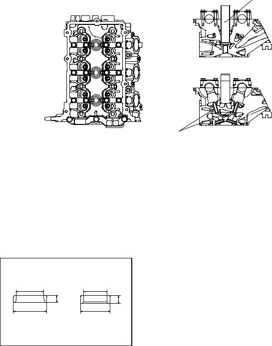
CYLINDER HEAD
Spark plug guide
Exhaust |
Intake |
side |
side |
Valve guide
AK305051AB
The cylinder head is made of aluminum alloy, which is lightweight and has an excellent cooling efficiency. The pentroof type combustion chamber has a spark plug in the center. The valve angle is relatively small, contributing to size reduction.
The intake and exhaust ports are arranged in a cross-flow construction. Each cylinder has a pair of intake ports on one side and a pair of exhaust ports on the other side.
Each of the intake and exhaust camshafts is supported by 4 bearings. On each camshaft, the thrust load is supported by No. 1 bearing. The No. 1 bearings for the intake and exhaust camshafts have a common bearing cap.
VALVE SEAT
Intake |
Exhaust |
d |
d |
h |
h |
D |
D |
Sintered alloy valve seat
Item |
Intake |
Exhaust |
D (Outer diameter) mm |
31.5 |
28 |
|
|
|
d (Inner diameter) mm |
26 |
22 |
|
|
|
h (height) mm |
6.6 |
7.3 |
|
|
|
AK305052AB
11A-4 |
ENGINE MECHANICAL <134> |
|
BASE ENGINE |
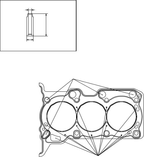
VALVE GUIDE
d
h
D
AK305053AB
The intake and exhaust valves use the same-design valve guide.
Item |
Specification |
D (Outer diameter) mm |
10.5 |
|
|
d (Inner diameter) mm |
4.5 |
|
|
h (height) mm |
34.5 |
|
|
CYLINDER HEAD GASKET
Oil hole
Water hole
AK305055AB
The metal gasket having the one layer of wave stopper is used for the cylinder head gasket.
ENGINE MECHANICAL <134> |
11A-5 |
BASE ENGINE |
|
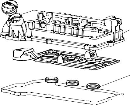
CYLINDER HEAD COVER
Cylinder head cover
 Plate
Plate
Oil seal
Cylinder head
 cover gasket
AK305057AB
A resin cylinder head cover is used for the cylinder head.
The oil plate and the oil seal are integrated with the cylinder head cover assembly.
 Loading...