


 Loading...
11A-0-1
ENGINE
4D68
CONTENTS
|
|
|
|
|
|
|
|
. . . . . . . . . . . . . . . . . . . . . . . . . . . . . . . . . . . . .GENERAL INFORMATION |
11A-0-3 |
|
|
1. |
SPECIFICATIONS . . . . . . . . . . . . . . . . . . . . . . . . . . . . . . . . . . . . . . . . . . |
11A-1-1 |
|
|
SERVICE SPECIFICATIONS . . . . . . . . . . . . . . . . . . . . . . . . . . . . |
11A-1-1 |
|
|
REWORK DIMENSIONS . . . . . . . . . . . . . . . . . . . . . . . . . . . . . . . . . |
11A-1-3 |
|
|
TORQUE SPECIFICATIONS . . . . . . . . . . . . . . . . . . . . . . . . . . . . . |
11A-1-4 |
|
|
NEW TIGHTENING METHOD - BY USE OF BOLTS |
|
|
|
TO BE TIGHTENED IN PLASTIC AREA . . . . . . . . . . . . . . . . |
11A-1-7 |
|
|
SEALANT . . . . . . . . . . . . . . . . . . . . . . . . . . . . . . . . . . . . . . . . . . . . . . . . . |
11A-1-7 |
|
|
FORM-IN-PLACE GASKET . . . . . . . . . . . . . . . . . . . . . . . . . . . . . . |
11A-1-8 |
|
2. |
SPECIAL TOOLS . . . . . . . . . . . . . . . . . . . . . . . . . . . . . . . . . . . . . . . . . . |
11A-2-1 |
|
3. |
DRIVE BELT AND GLOW PLUG . . . . . . . . . . . . . . . . . . . . . . . . . . |
11A-3-1 |
|
4. |
TIMING BELT . . . . . . . . . . . . . . . . . . . . . . . . . . . . . . . . . . . . . . . . . . . . . . . |
11A-4-1 |
|
5. |
GLOW PLUG, FUEL INJECTION PUMP |
|
|
|
AND INJECTION NOZZLE . . . . . . . . . . . . . . . . . . . . . . . . . . . . . . . . |
11A-5-1 |
|
6. |
INTAKE AND EXHAUST MANIFOLDS . . . . . . . . . . . . . . . . . . . . |
11A-6-1 |
|
7. |
WATER PUMP, THERMOSTAT, HOSE AND PIPES . . . . . . |
11A-7-1 |
|
8.ROCKER ARMS, ROCKER SHAFT AND CAMSHAFT . . . 11A-8-1
9.CYLINDER HEAD, VALVES AND VALVE SPRINGS . . . . . 11A-9-1
10.FRONT CASE, COUNTERBALANCE SHAFTS
AND OIL PAN . . . . . . . . . . . . . . . . . . . . . . . . . . . . . . . . . . . . . . . . . . . . . . . 11A-10-1
11. PISTONS AND CONNECTING RODS . . . . . . . . . . . . . . . . . . . . . 11A-11-1 12. CRANKSHAFT, CYLINDER BLOCK AND FLYWHEEL . . . 11A-12-1
|
|
|
E Mitsubishi Motors Corporation |
Dec. 1996 |
PWEE9609 |

11A-0-2
NOTES
E Mitsubishi Motors Corporation |
Dec. 1996 |
PWEE9609 |

4D68 ENGINE (E-W) - General Information |
11A-0-3 |
|
|
GENERAL INFORMATION
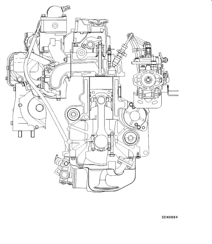
SECTIONAL VIEW OF ENGINE
E Mitsubishi Motors Corporation |
Dec. 1996 |
PWEE9609 |
11A-0-4 |
4D68 ENGINE (E-W) - General Information |
|
|
SECTIONAL VIEW OF ENGINE
E Mitsubishi Motors Corporation |
Dec. 1996 |
PWEE9609 |

|
|
4D68 ENGINE (E-W) - General Information |
11A-0-5 |
|||
|
|
|
|
|
|
|
GENERAL SPECIFICATIONS |
|
|
|
|||
|
|
|
|
|
|
|
Descriptions |
|
|
|
Specifications |
|
|
|
|
|
|
|
|
|
Type |
|
|
|
Diesel engine |
|
|
|
|
|
|
|
|
|
Number of cylinders |
|
4 in-line |
|
|||
|
|
|
|
|
|
|
Combustion chamber |
|
Swirl chamber |
|
|||
|
|
|
|
|
|
|
Total displacement dm3 |
|
1.998 |
|
|||
Cylinder bore mm |
|
|
|
82.7 |
|
|
|
|
|
|
|
|
|
Piston stroke mm |
|
|
|
93 |
|
|
|
|
|
|
|
|
|
Compression ratio |
|
|
|
22.4 |
|
|
|
|
|
|
|
|
|
Valve timing |
|
Intake valve |
|
Opens (BTDC) |
20° |
|
|
|
|
|
|
|
|
|
|
|
|
Closes (ABDC) |
48° |
|
|
|
|
|
|
|
|
|
|
Exhaust valve |
|
Opens (BBDC) |
54° |
|
|
|
|
|
|
|
|
|
|
|
|
Closes (ATDC) |
22° |
|
|
|
|
|
|
|
|
Lubrication system |
|
|
|
Pressure feed, full-flow filtration |
|
|
|
|
|
|
|
|
|
Oil pump type |
|
|
|
External gear type |
|
|
|
|
|
|
|
|
|
Cooling system |
|
|
|
Water-cooled |
|
|
|
|
|
|
|
|
|
Water pump type |
|
|
|
Centrifugal impeller type |
|
|
|
|
|
|
|
|
|
EGR type |
|
|
|
Single type |
|
|
|
|
|
|
|
||
Fuel system |
|
|
|
Electronic control distributor-type injection pump |
||
|
|
|
|
|
|
|
Supercharging |
|
|
|
Turbocharger |
|
|
|
|
|
|
|
|
|
Rocker arm |
|
|
|
Roller type |
|
|
|
|
|
|
|
|
|
Adjusting screw |
|
|
|
Elephant foot type |
|
|
|
|
|
|
|
|
|
Oil lever sensor |
|
|
|
Provided |
|
|
|
|
|
|
|
|
|
E Mitsubishi Motors Corporation |
Dec. 1996 |
PWEE9609 |

4D68 ENGINE (E-W) - Specifications |
11A-1-1 |
||
|
|
|
|
1. SPECIFICATIONS |
|
|
|
SERVICE SPECIFICATIONS |
|
|
|
|
|
|
|
Item |
|
Standard value |
Limit |
|
|
|
|
Drive belt and glow plug |
|
|
|
|
|
|
|
Glow plug resistance W |
|
0.5 |
- |
|
|
|
|
Timing belt |
|
|
|
|
|
|
|
Timing belt deflection mm |
|
4.0- 5.0 |
- |
|
|
|
|
Timing belt “B” deflection mm |
|
5.0- 7.0 |
- |
|
|
|
|
Rocker arms, rocker shaft and camshaft |
|
|
|
|
|
|
|
Camshaft cam height mm |
Intake |
41.90 |
41.40 |
|
|
|
|
|
Exhaust |
41.96 |
41.46 |
|
|
|
|
Valve clearance (on cold engine) mm |
Intake |
0.25 |
- |
|
|
|
|
|
Exhaust |
0.35 |
- |
|
|
|
|
Camshaft journal O.D. mm |
|
30.0 |
- |
|
|
|
|
Cylinder head, valves and valve springs |
|
|
|
|
|
|
|
Cylinder head gasket surface flatness mm |
|
Within 0.03 |
0.2 |
|
|
|
|
Cylinder head overall height mm |
|
86.9- 87.1 |
- |
|
|
|
|
Valve overall length mm |
Intake |
114.05 |
113.55 |
|
|
|
|
|
Exhaust |
113.80 |
113.30 |
|
|
|
|
Thickness of valve head (margin) mm |
|
1.5 |
0.7 |
|
|
|
|
Valve stem O.D. mm |
|
6.0 |
- |
|
|
|
|
Valve face angle |
|
45°- 45.5° |
- |
|
|
|
|
Valve stem to guide clearance mm |
|
0.05- 0.09 |
0.15 |
|
|
|
|
Valve spring free length mm |
|
49.1 |
48.1 |
|
|
|
|
Valve load/installed height N/mm |
|
240/37.9 |
- |
|
|
|
|
Valve spring out-of-squareness |
|
2° or less |
Max. 4° |
|
|
|
|
Valve seat valve contact width mm |
|
0.9- 1.3 |
- |
|
|
|
|
Valve stem projection mm |
|
43.45 |
43.95 |
|
|
|
|
Valve guide I.D. mm |
|
8.0 |
- |
|
|
|
|
Valve guide projection from cylinder head upper surface mm |
|
15 |
- |
|
|
|
|
Cylinder head bolt shank length mm |
|
- |
119.7 |
|
|
|
|
Front case, counterbalance shafts and oil pan |
|
|
|
|
|
|
|
Oil cooler by-pass valve dimension (L) [Normal temperature] mm |
|
34.5 |
- |
|
|
|
|
E Mitsubishi Motors Corporation |
Dec. 1996 |
PWEE9609 |

11A-1-2 |
4D68 ENGINE (E-W) - Specifications |
|
||
|
|
|
|
|
|
|
|
|
|
Item |
|
|
Standard value |
Limit |
|
|
|
|
|
Oil cooler by-pass valve dimension (L) [by-pass hole closing temperature |
40.0 |
- |
||
(97103°C or more)] mm |
|
|
|
|
|
|
|
|
|
Oil pump side clearance |
|
Drive gear |
0.08- 0.14 |
- |
|
|
|
|
|
|
|
Driven gear |
0.06- 0.12 |
- |
|
|
|
|
|
Pistons and connecting rods |
|
|
|
|
|
|
|
|
|
Piston O.D. mm |
|
|
82.7 |
- |
|
|
|
|
|
Piston ring to piston ring groove clearance mm |
No. 1 |
0.05- 0.07 |
0.15 |
|
|
|
|
|
|
|
|
No. 2 |
0.05- 0.07 |
0.15 |
|
|
|
|
|
Piston ring end gap mm |
|
No. 1 |
0.20- 0.32 |
0.8 |
|
|
|
|
|
|
|
No. 2 |
0.35- 0.50 |
0.8 |
|
|
|
|
|
|
|
Oil ring |
0.10- 0.30 |
0.8 |
|
|
|
|
|
Piston pin O.D. mm |
|
|
25.0 |
- |
|
|
|
|
|
Crankshaft pin oil clearance mm |
|
0.02- 0.05 |
0.1 |
|
|
|
|
|
|
Connecting rod big end side clearance mm |
|
0.10- 0.25 |
0.4 |
|
|
|
|
|
|
Connecting rod bushing I.D. mm |
|
25.01525.025 |
- |
|
|
|
|
||
Connecting rod bushing bend (Parallelism between big end center line and small |
0.05 |
- |
||
end center line) mm |
|
|
|
|
|
|
|
||
Connecting rod bushing twist (Deflection between big end center line and small |
0.1 |
- |
||
end center line) mm |
|
|
|
|
|
|
|
|
|
Crankshaft, cylinder block and flywheel |
|
|
|
|
|
|
|
|
|
Crankshaft end play mm |
|
|
0.05- 0.18 |
0.25 |
|
|
|
|
|
Crankshaft journal O.D. mm |
|
|
57.0 |
- |
|
|
|
|
|
Crankshaft pin O.D. mm |
|
|
45.0 |
- |
|
|
|
|
|
Crankshaft journal oil clearance mm |
|
0.02- 0.04 |
0.1 |
|
|
|
|
|
|
Cylinder block gasket surface flatness mm |
|
0.05 |
0.1 |
|
|
|
|
|
|
Cylinder block overall height mm |
|
235 |
- |
|
|
|
|
|
|
Cylinder bore I.D. mm |
|
|
82.7082.73 |
- |
|
|
|
|
|
Cylinder conicity mm |
|
|
0.01 |
- |
|
|
|
|
|
Piston to cylinder clearance mm |
|
0.03- 0.05 |
- |
|
|
|
|
|
|
Cylinder sleeve press-fitting force N |
|
2,200 or more |
- |
|
|
|
|
|
|
Piston projection mm |
|
|
0.823 |
- |
|
|
|
|
|
E Mitsubishi Motors Corporation |
Dec. 1996 |
PWEE9609 |

4D68 ENGINE (E-W) - Specifications |
11A-1-3 |
|||
|
|
|
|
|
REWORK DIMENSIONS |
|
|
|
|
|
|
|
|
|
Item |
|
Standard value |
Limit |
|
|
|
|
|
|
Cylinder head, valves and valve springs |
|
|
|
|
|
|
|
|
|
Cylinder head oversize valve guide hole |
0.05 O.S. |
13.05013.068 |
- |
|
(both intake and exhaust) mm |
|
|
|
|
0.25 O.S. |
13.25013.268 |
- |
||
|
||||
|
|
|
|
|
|
0.50 O.S. |
13.50013.518 |
- |
|
|
|
|
|
|
Cylinder head oversize intake valve seat ring hole mm |
0.3 O.S. |
38.30038.325 |
- |
|
|
|
|
|
|
|
0.6 O.S. |
38.60038.625 |
- |
|
|
|
|
|
|
Cylinder head oversize exhaust valve seat ring hole mm |
0.3 O.S. |
34.30034.325 |
- |
|
|
|
|
|
|
|
0.6 O.S. |
34.60034.625 |
- |
|
|
|
|
|
|
NOTE |
|
|
|
|
O.D.: Outer diameter |
|
|
|
|
I.D.: Inner diameter
O.S.: Oversize diameter
E Mitsubishi Motors Corporation |
Dec. 1996 |
PWEE9609 |

11A-1-4 |
4D68 ENGINE (E-W) - Specifications |
|
|
|
|
|
|
TORQUE SPECIFICATIONS |
|
||
|
|
|
|
Items |
|
|
Nm |
|
|
|
|
Drive belt and glow plug |
|
|
|
|
|
|
|
Oil level gauge guide bolt |
|
|
13 |
|
|
|
|
Pulley bolt (for power steering pump drive) |
9 |
||
|
|
|
|
Alternator brace bolt |
|
|
23 |
|
|
|
|
Lock bolt |
|
|
23 |
|
|
|
|
Adjusting bolt |
|
|
10 |
|
|
|
|
Alternator pivot nut |
|
|
44 |
|
|
|
|
Crankshaft pulley bolt |
|
|
25 |
|
|
|
|
Glow plug |
|
|
18 |
|
|
|
|
Glow plug nut |
|
|
1.8 |
|
|
|
|
Timing belt |
|
|
|
|
|
|
|
Timing belt cover |
|
Flange bolt |
11 |
|
|
|
|
|
|
Washer bolt |
9 |
|
|
|
|
Crankshaft position sensor bolt |
|
|
9 |
|
|
|
|
Timing belt tensioner bolt |
|
|
48 |
|
|
|
|
Tensioner spring bolt |
|
|
13 |
|
|
|
|
Timing belt idler pulley bolt |
|
|
48 |
|
|
|
|
Camshaft sprocket bolt |
|
|
88 |
|
|
||
Injection pump sprocket flange bolt |
9 |
||
|
|
|
|
Injection pump sprocket nut |
|
|
83 |
|
|
|
|
Crankshaft bolt |
|
|
118 |
|
|
|
|
Oil pump sprocket nut |
|
|
54 |
|
|
|
|
Tensioner “B” bolt |
|
|
18 |
|
|
||
Counterbalance shaft sprocket bolt |
45 |
||
|
|
|
|
Timing belt rear cover bolt |
|
|
11 |
|
|
||
Engine support bracket bolt and nut |
49 |
||
|
|
||
Glow plug, fuel injection pump and injection nozzle |
|
||
|
|
|
|
Injection pipe |
|
|
29 |
|
|
|
|
Injection pipe clamp bolt |
|
|
5 |
|
|
|
|
Fuel pipe bolt |
|
|
13 |
|
|
|
|
Engine hanger bolt |
|
|
18 |
|
|
|
|
Fuel injection pump bolt |
|
|
23 |
|
|
|
|
Fuel injection pump nut |
|
|
18 |
|
|
|
|
Fuel injection pump stay bolt |
|
|
35 |
|
|
|
|
Fuel return pipe nut |
|
|
29 |
|
|
|
|
E Mitsubishi Motors Corporation |
Dec. 1996 |
PWEE9609 |

4D68 ENGINE (E-W) - Specifications |
11A-1-5 |
|
|
|
|
|
|
|
Items |
|
Nm |
|
|
|
Injection nozzle |
|
54 |
|
|
|
Fuel injection pump bracket nut |
|
23 |
|
|
|
Intake and exhaust manifold |
|
|
|
|
|
Air temperature sensor |
|
14 |
|
|
|
Air intake fitting bolt |
|
17 |
|
|
|
EGR valve bolt |
|
24 |
|
|
|
EGR pipe bolt and nut |
|
17 |
|
|
|
Turbocharger heat protector bolt |
M8 |
13 |
|
|
|
|
M6 |
11 |
|
|
|
Exhaust fitting heat protector bolt |
|
13 |
|
|
|
Water pipe “A” and “B” eye bolt |
|
30 |
|
|
|
Water pipe “A” and “B” bolt |
|
10 |
|
|
|
Oil pipe eye bolt |
|
16 |
|
|
|
Exhaust fitting bolt and nut |
|
59 |
|
|
|
Oil return pipe bolt |
|
9 |
|
|
|
Heat protector front and rear bolt |
|
13 |
|
|
|
Turbocharger assembly bolt |
|
59 |
|
|
|
Exhaust manifold bolt and nut |
|
29 |
|
|
|
Alternator brace stay bolt |
|
23 |
|
|
|
Intake manifold bolt and nut |
|
17 |
|
|
|
Water pump, thermostat, hose and pipe |
|
|
|
|
|
Oil pipe eye bolt |
|
16 |
|
|
|
Oil return pipe eye bolt |
|
17 |
|
|
|
Oil return pipe bolt |
|
9 |
|
|
|
Engine coolant temperature sensor |
|
35 |
|
|
|
Engine coolant temperature gauge unit |
|
11 |
|
|
|
Cover bolt |
|
19 |
|
|
|
Water pump bolt |
|
13 |
|
|
|
Water inlet pipe bolt |
|
12 |
|
|
|
Vacuum pump bolt |
|
22 |
|
|
|
Water inlet fitting bolt |
|
23 |
|
|
|
Water outlet fitting bolt |
|
12 |
|
|
|
Thermostat housing bolt |
|
23 |
|
|
|
Rocker arms, rocker shaft and camshaft |
|
|
|
|
|
Rocker cover bolt |
|
6 |
|
|
|
Rocker shaft bolt |
|
29 |
|
|
|
E Mitsubishi Motors Corporation |
Dec. 1996 |
PWEE9609 |
11A-1-6 |
4D68 ENGINE (E-W) - Specifications |
|
|
|
|
|
|
|
|
|
|
|
|
|
Items |
|
|
Nm |
|
|
|
|
|
|
Adjusting nut |
|
|
15 |
|
|
|
|
|
|
Camshaft bearing cap bolt |
|
M8 ¢ 25, M8 ¢ 40 |
20 |
|
|
|
|
|
|
|
|
M8 ¢ 55 |
29 |
|
|
|
|
|
|
Cylinder head, valves and valve springs |
|
|
||
|
|
|
|
|
Cylinder head bolt |
|
|
90 |
|
|
|
|
¯ |
|
|
|
|
Fully loosen |
|
|
|
|
¯ |
|
|
|
|
40 |
+ 90° + 90° |
|
|
|
||
Front case, counterbalance shafts and oil pan |
|
|
||
|
|
|
|
|
Drain plug |
|
|
39 |
|
|
|
|
|
|
Oil level sensor bolt |
|
|
9 |
|
|
|
|
|
|
Oil pan bolt |
|
|
7 |
|
|
|
|
|
|
Oil screen bolt |
|
|
19 |
|
|
|
|
|
|
Oil cooler by-pass valve |
|
|
54 |
|
|
|
|
|
|
Oil pressure switch |
|
|
10 |
|
|
|
|
|
|
Relief plug |
|
|
44 |
|
|
|
|
|
|
Oil filter bracket bolt |
|
|
18 |
|
|
|
|
|
|
Plug |
|
|
23 |
|
|
|
|
|
|
Flange bolt |
|
|
36 |
|
|
|
|
|
|
Front case bolt |
|
|
24 |
|
|
|
|
|
|
Oil pump cover |
|
Bolt |
16 |
|
|
|
|
|
|
|
|
Screw |
10 |
|
|
|
|
|
|
Pistons and connection rods |
|
|
|
|
|
|
|
|
|
Connecting rod cap nut |
|
|
20 |
|
|
|
|
¯ |
|
|
|
|
+90° - 100° |
|
|
|
|
||
Crankshaft, cylinder block and flywheel |
|
|
||
|
|
|
|
|
Flywheel bolt |
|
|
132 |
|
|
|
|
|
|
Rear plate bolt |
|
|
11 |
|
|
|
|
|
|
Oil seal case bolt |
|
|
11 |
|
|
|
|
|
|
Bearing cap bolt |
|
|
25 |
|
|
|
|
¯ |
|
|
|
|
+90° - 100° |
|
|
|
|
|
|
Check valve |
|
|
15 |
|
|
|
|
|
|
E Mitsubishi Motors Corporation |
Dec. 1996 |
PWEE9609 |

4D68 ENGINE (E-W) - Specifications |
11A-1-7 |
|
|
NEW TIGHTENING METHOD - BY USE OF BOLTS TO BE TIGHTENED IN PLASTIC AREA
A new type of bolts, to be tightened in plastic area, is currently used some parts of the engine. The tightening method for the bolts is different from the conventional one. Be sure to observe the method described in the text when tightening the bolts.
Service limits are provided for the bolts. Make sure that the service limits described in the text are strictly observed.
DAreas where the bolts are in use:
(1)Cylinder head bolts
(2)Main bearing cap bolts
(3)Connecting rod cap bolts
DTightening method
After tightening the bolts to the specified torque, tighten them another 90° or 180° (twice 90°). The tightening method varies on different areas. Observe the tightening method described in the text.
SEALANT
Items |
Specified sealant |
Quantity |
|
|
|
|
|
Thermostat housing |
Mitsubishi Genuine Part No. MD970389 or equivalent |
As required |
|
|
|
|
|
Engine coolant temperature |
3M |
Nut Locking Part No. 4171 or equivalent |
As required |
gauge unit |
|
|
|
|
|
|
|
Oil pressure switch |
3M |
ATD Part No. 8660 or equivalent |
As required |
|
|
|
|
Water outlet fitting |
Mitsubishi Genuine Part No. MD970389 or equivalent |
As required |
|
|
|
|
|
Oil pan |
Mitsubishi Genuine Part No. MD970389 or equivalent |
As required |
|
|
|
|
|
Oil seal case |
Mitsubishi Genuine Part No. MD970389 or equivalent |
As required |
|
|
|
|
|
Cover |
Mitsubishi Genuine Part No. MD970389 or equivalent |
As required |
|
|
|
|
|
Camshaft bearing cap |
3M |
ATD Part No. 8660 or equivalent |
As required |
|
|
|
|
E Mitsubishi Motors Corporation |
Dec. 1996 |
PWEE9609 |

11A-1-8 |
4D68 ENGINE (E-W) - Specifications |
|
|
FORM-IN-PLACE GASKET
The engine has several areas where the form-in-place gasket (FIPG) is in use. To ensure that the gasket fully serves its purpose, it is necessary to observe some precautions when applying the gasket. Bead size, continuity and location are of paramount importance. Too thin a bead could cause leaks. Too thick a bead, on the other hand, could be squeezed out of location, causing blocking or narrowing of the fluid feed line. To eliminate the possibility of leaks from a joint, therefore, it is absolutely necessary to apply the gasket evenly without a break, while observing the correct bead size.
The FIPG used in the engine is a room temperature vulcanization (RTV) type and is supplied in a 100-gram tube (Part No. MD970389 or MD997110). Since the RTV hardens as it reacts with the moisture in the atmospheric air, it is normally used in the metallic flange areas. The FIPG, Part No. MD970389, can be used for sealing both engine oil and coolant, while Part No. 997110 can only be used for engine oil sealing.
Disassembly
The parts assembled with the FIPG can be easily disassembled without use of a special method. In some cases, however, the sealant between the joined surfaces may have to be broken by lightly striking with a mallet or similar tool. A flat and thin gasket scraper may be lightly hammered in between the joined surfaces. In this case, however, case must be taken to prevent damage to the joined surfaces. For removal of the oil pan, the special tool “Oil Pan Remover” (MD998727) is available. Be sure to use the special tool to remove the oil pan.
Surface Preparation
Thoroughly remove all substances deposited on the gasket application surfaces, using a gasket scraper or wire brush. Check to ensure that the surfaces to which the FIPG is to be applied is flat. Make sure that there are no oils, greases and foreign substances deposited on the application surfaces. Do not forget to remove the old sealant remained in the bolt holes.
Form-In-Place Gasket Application
When assembling parts with the FIPG, you must observe some precautions, but the procedures is very simple as in the case of a conventional precut gasket.
Applied FIPG bead should be of the specified size and without breaks. Also be sure to encircle the bolt hole circumference with a completely continuous bead. The FIPG can be wiped away unless it is hardened. While the FIPG is still moist (in less than 15 minutes), mount the parts in position. When the parts are mounted, make sure that the gasket is applied to the required area only. In addition, do not apply any oil or water to the sealing locations or start the engine until a sufficient amount of time (about one hour) has passed after installation is completed.
The FIPG application procedure may vary on different areas. Observe the procedure described in the text when applying the FIPG.
E Mitsubishi Motors Corporation |
Dec. 1996 |
PWEE9609 |
|
4D68 ENGINE (E-W) - Special Tools |
11A-2-1 |
||
|
|
|
|
|
2. SPECIAL TOOLS |
|
|
|
|
|
|
|
|
|
Tool |
Number |
Name |
Use |
|
|
|
|
|
|
|
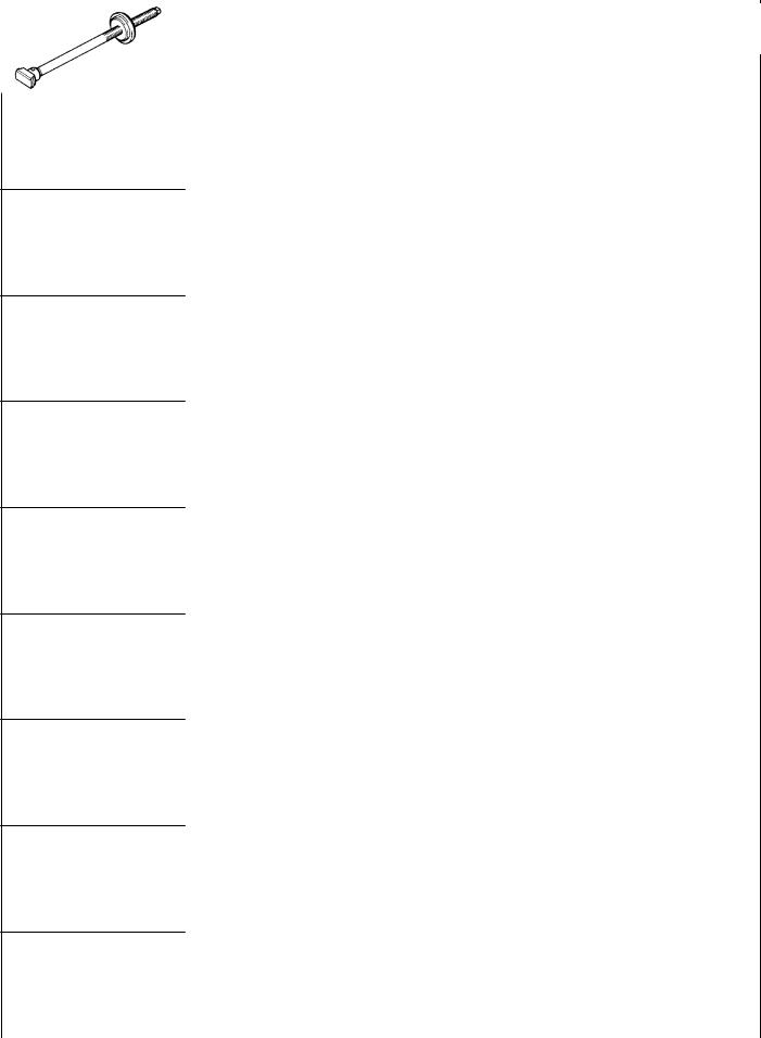
MB990767 |
End yoke holder |
Holding camshaft sprocket or fuel injection |
|
|
|
|
pump when loosening or tightening bolts. |
|
|
|
|
Use with MD998719 |
|
|
|
|
|
|
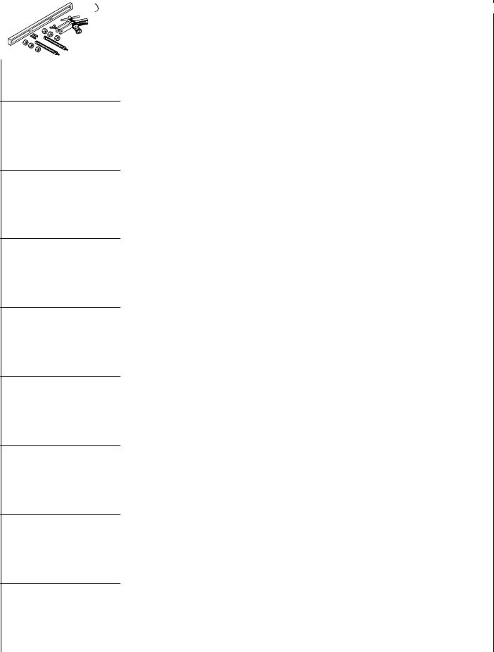
MB991603 |
Bearing installer |
A guide for removal and installation of |
|
stopper |
counterbalance shaft left rear bearing |
|
|
|
MD990938 |
Handle |
Installation of crankshaft rear oil seal |
|
|
(Use with MD998776) |
|
|
|
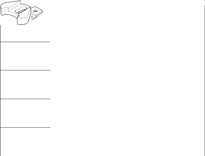
MB991654 |
Cylinder head bolt |
Tightening and loosening of cylinder head bolt |
|
wrench |
|
|
|
|
MD998115 |
Valve guide |
Removal and installation of valve guide |
|
installer |
|
|
|
|
MD998162 |
Plug wrench |
Removal and installation of front case cap plug |
|
|
(Use with MD998783) |
|
|
|
MD998285 |
Crankshaft front oil |
Guide for installation of crankshaft front oil seal |
|
seal guide |
|
|
|
|
MD998371 |
Silent shaft bearing |
Removal of counterbalance shaft front bearing |
|
puller |
|
|
|
|
|
MD998372 |
Silent shaft bearing |
Removal of counterbalance shaft rear bearing |
|
|
puller |
|
|
|
|
|
E Mitsubishi Motors Corporation |
Dec. 1996 |
PWEE9609 |
11A-2-2 |
4D68 ENGINE (E-W) - Special Tools |
||
|
|
|
|
|
|
|
|
Tool |
Number |
Name |
Use |
|
|
|
|
|
MD998375 |
Crankshaft front oil |
Installation of crankshaft front oil seal |
|
|
seal installer |
|
|
|
|
|
MD998388 |
Injection pump |
Removal of injection pump sprocket |
|
sprocket puller |
|
|
|
|
MD998702 |
Connecting-rod |
Replacement of connecting-rod small-end |
|
small-end bushing |
bushing |
|
replacement tool |
|
|
|
|
MD998705 |
Silent shaft bearing |
Installation of counterbalance shaft bearing |
|
installer |
|
|
|
|
MD998713 |
Camshaft oil seal |
Installation of camshaft oil seal |
|
installer |
|
|
|
|
MD998719 |
Pulley holder pin |
Use with MB990767 |
|
(2) |
|
|
|
|
MD998727 |
Oil pan sealer |
Removal of oil pan |
|
cutter |
|
|
|
|
MD998729 |
Valve stem seal |
Installation of valve stem seal |
|
installer |
|
|
|
|
|
MD998772 |
Valve spring |
Compression of valve spring |
|
|
compressor |
|
|
|
|
|
E Mitsubishi Motors Corporation |
Dec. 1996 |
PWEE9609 |
|
4D68 ENGINE (E-W) - Special Tools |
11A-2-3 |
||
|
|
|
|
|
|
|
|
|
|
Tool |
Number |
Name |
Use |
|
|
|
|
|
|
|
MD998776 |
Crankshaft rear oil |
Installation of crankshaft rear oil seal |
|
|
|
seal installer |
(Use with MB990938) |
|
|
|
|
|
|
MD998778 |
Crankshaft |
Removal of crankshaft sprocket |
|
sprocket puller |
|
|
|
|
MD998781 |
Flywheel stopper |
Holding of flywheel and drive plate |
|
|
|
MD998783 |
Plug wrench |
Removal and installation of front case cap plug |
|
retainer |
(Use with MD998162) |
|
|
|
|
MD998785 |
Sprocket stopper |
Holding of counterbalance shaft sprocket |
|
|
|
|
E Mitsubishi Motors Corporation |
Dec. 1996 |
PWEE9609 |
4D68 ENGINE (E-W) - Drive Belt and Glow Plug |
11A-3-1 |
|
|
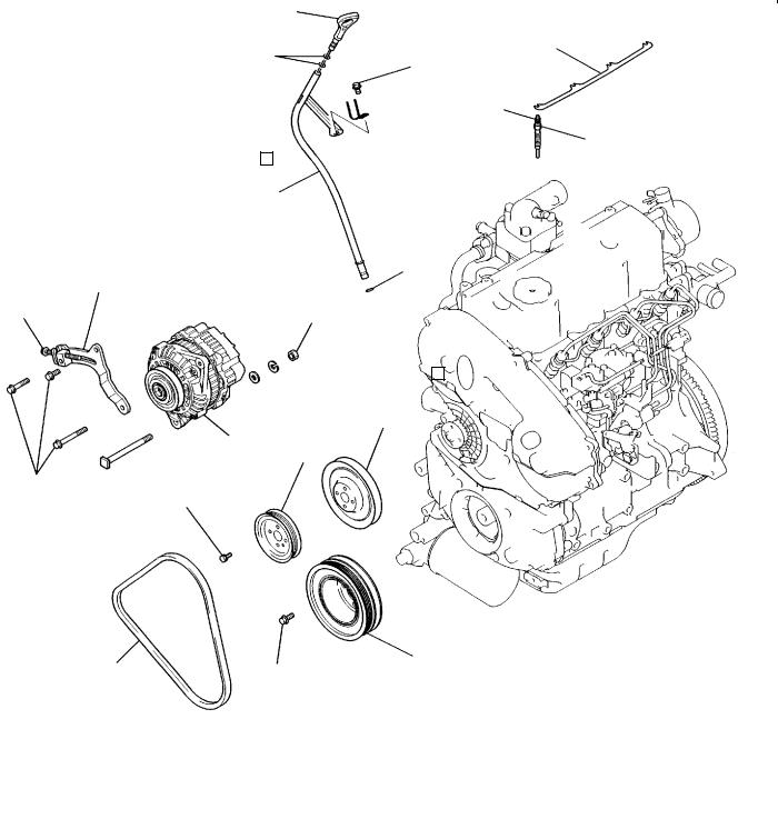
3. DRIVE BELT AND GLOW PLUG
REMOVAL AND INSTALLATION
1
|
2 |
11 |
|
13 Nm |
|
|
||
|
|
|
|
|
1.8 Nm |
12
3
|
4 |
|
|
|
|
10 Nm |
8 |
|
44 Nm |
|
|
|
|
7
9
6
23 Nm
9 Nm
5 |
25 Nm |
10 |
|
18 Nm
DEN0885
Removal steps |
|
|
|
1. |
Oil level gauge |
7. |
Water pump pulley |
2. |
O-ring |
8. |
Alternator brace |
3. |
Oil level gauge guide |
9. |
Alternator |
4. |
O-ring |
10. |
Crankshaft pulley |
5. |
Drive belt (V-type) |
11. |
Glow plug plate |
6. |
Pulley (for power steering pump |
AA" "AA 12. |
Glow plug |
|
drive) |
|
|
E Mitsubishi Motors Corporation |
Dec. 1996 |
PWEE9609 |
11A-3-2 4D68 ENGINE (E-W) - Drive Belt and Glow Plug
REMOVAL SERVICE POINTS
AA" GLOW PLUG REMOVAL
(1)When removing the glow plug, you may loosen using a tool up to the point where one or more threads are left in engagement. Beyond this point, loosen with fingers.
Caution
D Do not reuse a glow plug that has been dropped from a height of 10 cm or more.
INSTALLATION SERVICE POINTS
"AA GLOW PLUG INSTALLATION
(1)When installing the glow plug, screw in one thread or more with fingers and then tighten with a tool.
Caution
DDo not reuse a glow plug that has been dropped from a height of 10 cm or more.
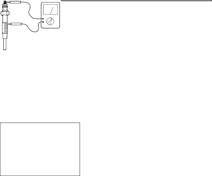
INSPECTION
GLOW PLUG
(1)Check the glow plugs for continuity between the terminal and the body as shown. Replace the glow plugs which show no continuity or too large a resistance.
Standard value: 0.5 W
DEL034
E Mitsubishi Motors Corporation |
Dec. 1996 |
PWEE9609 |
4D68 ENGINE (E-W) - Timing Belt |
11A-4-1 |
|
|
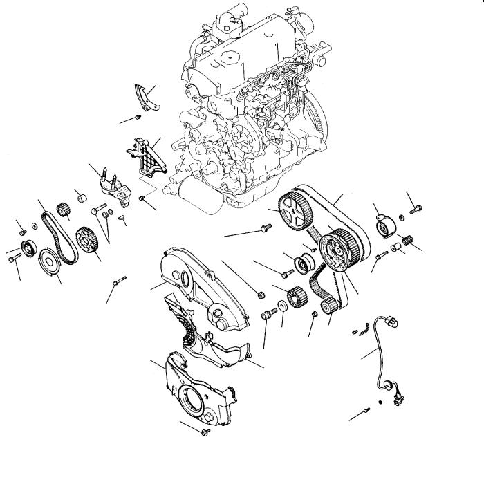
4. TIMING BELT
REMOVAL AND INSTALLATION
27
|
|
11 Nm |
|
|
26 |
|
|
28 |
21 |
23 |
|
|
|
|
45 Nm |
22 |
11 Nm |
|
25 |
|
|
|
|
20 |
|
49 Nm |
|
|
|
|
|
24 |
18 Nm |
18 |
1 |
|
||
|
|
11 Nm |
3
9 Nm
Removal steps
1.Timing belt front upper cover
2.Timing belt front center cover
3.Timing belt front lower cover
4.Crankshaft position sensor
AA" "IA 5. Timing belt
"HA 6. Timing belt tensioner
7.Tensioner spacer
8.Tensioner spring
9.Timing belt idler pulley AB" "GA 10. Camshaft sprocket bolt
11.Camshaft sprocket
12.Flange
AC" "FA 13. Injection pump sprocket nut AD" 14. Injection pump sprocket
|
|
|
|
|
|
|
|
|
|
5 |
48 Nm |
|
|
|
|
|
11 |
|
|
|
6 |
||
|
|
|
|
|
|
|
14 |
|
|||
|
|
|
|
|
|
|
|
|
|
|
|
|
|
|
|
|
|
|
|
|
|
|
|
88 Nm |
10 |
|
|
|
|
9 Nm |
|
||||
|
|
|
|
|
|
|
|
|
|
||
83 Nm |
|
|
|
|
|
|
|
9 |
|
7 8 |
|
|
|
48 Nm |
|
|
|||||||
|
|
|
|
|
|
|
|
||||
|
|
|
|
|
|
|
|
|
|
|
|
|
|
|
|
|
|
|
|
|
|
|
|
|
|
13 |
|
17 |
|
|
|
13 Nm |
|||
|
|
|
|
|
|
|
|
|
12 |
||
|
|
|
|
|
|
|
|
|
|
|
|
|
|
|
|
|
|
|
|
|
19 |
|
|
|
|
|
|
|
15 |
|
16 |
|
|||
|
|
|
|
|
|
|
|
|
|
54 Nm |
|
|
|
|
|
|
|
|
|
|
|
|
|
118 Nm |
4 |
|
2 |
||
|
|
|
9 Nm |
|
|
DEN0886 |
AE" "EA 15. |
Crankshaft bolt |
|
AF" |
16. |
Special washer |
17. |
Crankshaft sprocket |
|
|
18. |
Crankshaft sensing blade |
AG" "DA 19. |
Oil pump sprocket |
|
|
20. |
Tensioner “B” |
AH" "CA 21. |
Timing belt “B” |
|
AI" |
"BA 22. |
Counterbalance shaft sprocket |
AJ" |
"AA 23. |
Spacer |
24. |
Crankshaft sprocket “B” |
|
|
25. |
Key |
|
26. |
Timing belt rear center cover |
|
27. |
Timing belt rear right cover |
|
28. |
Engine support bracket |
E Mitsubishi Motors Corporation |
Dec. 1996 |
PWEE9609 |

11A-4-2 |
4D68 ENGINE (E-W) - Timing Belt |
|
|
REMOVAL SERVICE POINTS
AA" TIMING BELT REMOVAL
(1)Using chalk, etc., mark an arrow on the back of the timing belt to indicate the direction of rotation. This is to ensure correct installation of the belt in case it is reused.
DEN0739
(2)Attach a bolt to the front end face of the timing belt tensioner. Fit an offset wrench onto the bolt and turn the wrench downward as shown to tighten the tensioner mounting bolt temporarily.
Caution
D Use such a short bolt as would not come into contact with the timing belt tensioner mounting
bolt at the rear end face when it is tightened.
(3) Remove the timing belt.
DEN0838
AB" CAMSHAFT SPROCKET BOLT LOOSENING
MB990767
MD998719
DEN0741
MB998719
AC" INJECTION PUMP SPROCKET NUT LOOSENING
MB990767
DEN0742
AD" INJECTION PUMP SPROCKET REMOVAL
(1)Do not strike the sprocket and drive shaft to remove these parts.
MD998388 |
|
DFU0625 |
|
E Mitsubishi Motors Corporation Dec. 1996 |
PWEE9609 |
4D68 ENGINE (E-W) - Timing Belt |
11A-4-3 |
|
|
MD998781
DEN0743
MD998778
DEN0744
Plug |
Screwdriver |
|
|
6EN0563 |
6EN0564 |
DEN0745
AE" CRANKSHAFT BOLT LOOSENING
AF" CRANKSHAFT SPROCKET REMOVAL
AG"OIL PUMP SPROCKET REMOVAL
(1)Before loosening the oil pump sprocket nut (flange nut), remove the timing belt and then the plug at the left side of the cylinder block and insert a Phillips screwdriver [shank diameter 8 mm] through the plug hole to keep the left counterbalance shaft in position.
Caution
D If the nut is loosened without removing the timing belt, the force produced by loosening the nut will be borne by the belt and can cause damage to the belt cogs.
AH" TIMING BELT “B” REMOVAL
(1)Using chalk, etc., mark an arrow on the back of the timing belt to indicate the direction of rotation. This is to ensure correct installation of the belt in case it is reused.
NOTE
(1)Water or oil on the belt shortens its life drastically, so the removed timing belt, sprocket, and tensioner must be free from oil and water. Do not immerse parts in cleaning solvent.
(2)If there is oil or water on any part, check the front case oil seals, camshaft oil seal and water pump for leaks.
E Mitsubishi Motors Corporation |
Dec. 1996 |
PWEE9609 |
Loading...