


601 diesel engine Shop Manual
GROUP INDEX |
|
HOW TO READ THIS MANUAL |
|
GENERAL ...................... |
• |
{for
industrial
use)
ENGINE ......................... |
• |
LUBRICATION .................. |
·lfl |
|
. |
FOREWORD |
|
This Shop Manual is published for the information and guid- |
|
|
ance of personnel responsible for maintenance of Mitsubishi |
|
|
601 series diesel engine, and includes procedures for ad- |
|
|
justment and maintenance services. |
|
|
We earnestly look forward to seeing that this manual is made |
|
|
full use of in orderto perform correct service with no wastage. |
|
( |
For more details, please consult your nearest authorized |
|
|
Mitsubishi dealer or distributor. |
|
|
Kindly note that the specifications and maintenance service |
|
|
figures are subject to change without prior notice in line with |
|
|
improvement which will be effected from time to time in the |
|
|
future. |
|
|
Applicable models |
|
|
6014 |
6014-T |
|
6015-T |
6016 |
|
6016-E |
6016-T |
|
6016-TE 6016-TL |
|
|
6016-TLE ··············SK330(N)LC-6E |
|
FUEL AND ENGINE CONTROL |
... • |
ELECTRONICALLY |
mf.11 |
CONTROLLED FUEL SYSTEM |
...... |
COOLING ....................... |
• |
INTAKE AND EXHAUST .......... |
• |
CLUTCH ........................ |
• |
ELECTRICAL SYSTEM ........... |
• |
SPECIAL EQUIPMENT ........... |
• |
NOTE; The parts marked"*" are deleted as |
|
they are not applicable to the SK330(N)LC-6E. |
|
©
2001
Mitsubishi Motors Corporation Printed in Japan
From the library of Barrington Diesel Club


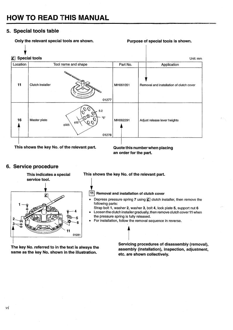
HOW TO
RE.AD
THIS MANUAL
HOW THIS MANUAL IS COMPILED . • • • • • . • • . • . . |
• • . • . . |
• . . . . |
||
GENERAL EXPLANATION OF THIS MANUAL . . • • • . . . . . |
. . . . . |
|||
TERMS AND UNITS . . . . • . • • . • • • • • • • • . . |
• . . |
• • • . . |
• • . • . • . • • . • |
|
ii iii vii


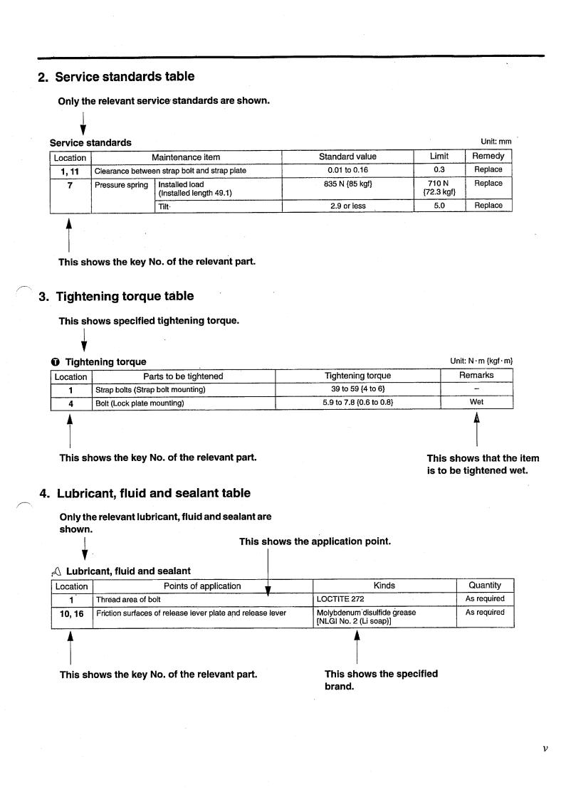
2. Service standards table Only the relevant service· standards are shown.
Service standards |
|
||
Location |
|
Maintenance item |
|
1'11 |
Clearance between strap bolt and strap plate |
||
|
|
||
7 |
Pressure spring |
Installed load |
|
(Installed length 49.1) |
|||
|
|
||
|
|
lilt· |
|
t This shows the key No. of the relevant part.
Standard value 0.01 to 0.16 835 N {85 kgf}
2.9 or less
Limit
0.3
710 N {72.3 kgf}
5.0
Unit: mm Remedy Replace Replace
Replace
3. Tightening torque table
|
This shows specified tightening torque. |
|
0 |
t |
|
Tightening torque |
||
Location |
Parts to be tightened |
|
|
1 |
Strap bolts (Strap bolt mounting) |
|
|
|
|
4 |
Bolt (Lock plate mounting) |
|
|
|
t This shows the key No. of the relevant part.
4. Lubricant, fluid and sealant table
Tightening torque 39 to 59 {4 to 6} 5.9 to 7.8 {0.6 to 0.8}
Unit: N ·m {kgf ·m}
Remarks
-
Wet
t
This shows that the item is to be tightened wet.
Only the relevant lubricant, fluid and sealant are shown. This shows the application point.
~ |
Lubricant, fluid and sealant |
Location |
Points of application |
1 |
|
|
|
1 |
Thread area of bolt |
|
10,16 |
Friction surfaces of release lever plate a!ld release lever |
|
t This shows the key No. of the relevant part.
Kinds
LOCTITE272
Molybdenum·disulfidegrease [NLGI No.2 (Li soap)]
t This shows the specified brand.
Quantity As required As required
v
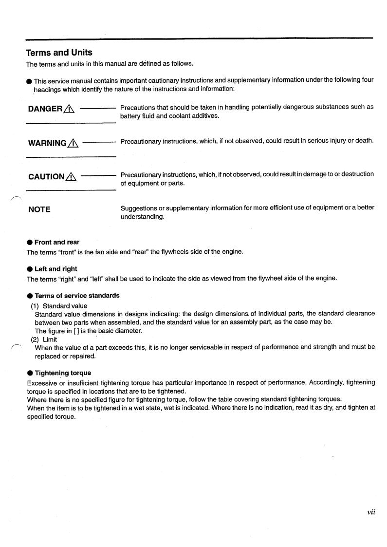
Terms
and
Units
The terms and units in this manual are defined as follows. |
|
|
e |
This service manual contains important cautionary instructions and supplementary |
information under the following four |
|
||
|
.headings which identify the nature of the instructions and information: |
|
DANGER,&.
Precautions that should be taken in handling potentially dangerous substances such as battery fluid and coolant additives.
WARNING_&.---
Precautionary instructions, which,
if not observed, could
result
in
serious injury or death.
CAUTION,&.
---
Precautionary instructiqns, which, if not observed, could of equipment or parts.
result in damage to
or
destruction
NOTE
Suggestions or supplementary information for more efficient use of equipment or a better understanding.
e
Front and rear
The terms ''front"is the fan side and "rear''the flywheels side of the engine.
e
Left and right
The terms
"right" and "left" shall
be
used to indicate the side as viewed from the flywheel side of the engine.
e
Terms of service standards
(1) Standard value Standard value dimensions in designs indicating: the design dimensions. of individual parts, the standard clearC\nce between two parts when assembled, and the standard value for an assembly part, as the case may be. The figure in [ ] is the basic diameter. (2) Limit When the value of a part exceeds this, it is no longer serviceable in respect of performance and strength and must be replaced or repaired.
e Tightening torque Excessive or insufficient tightening torque has particular importance in respect of performance. Accordingly, tightening torque is specified in locations that are to be tightened. Where there is no specified figure for tightening torque, follow the table covering standard tightening torques. When the item is to be tightened in a wet state, wet is indicated. Where there is no indication, read it as dry, and tighten at specified torque.
vii

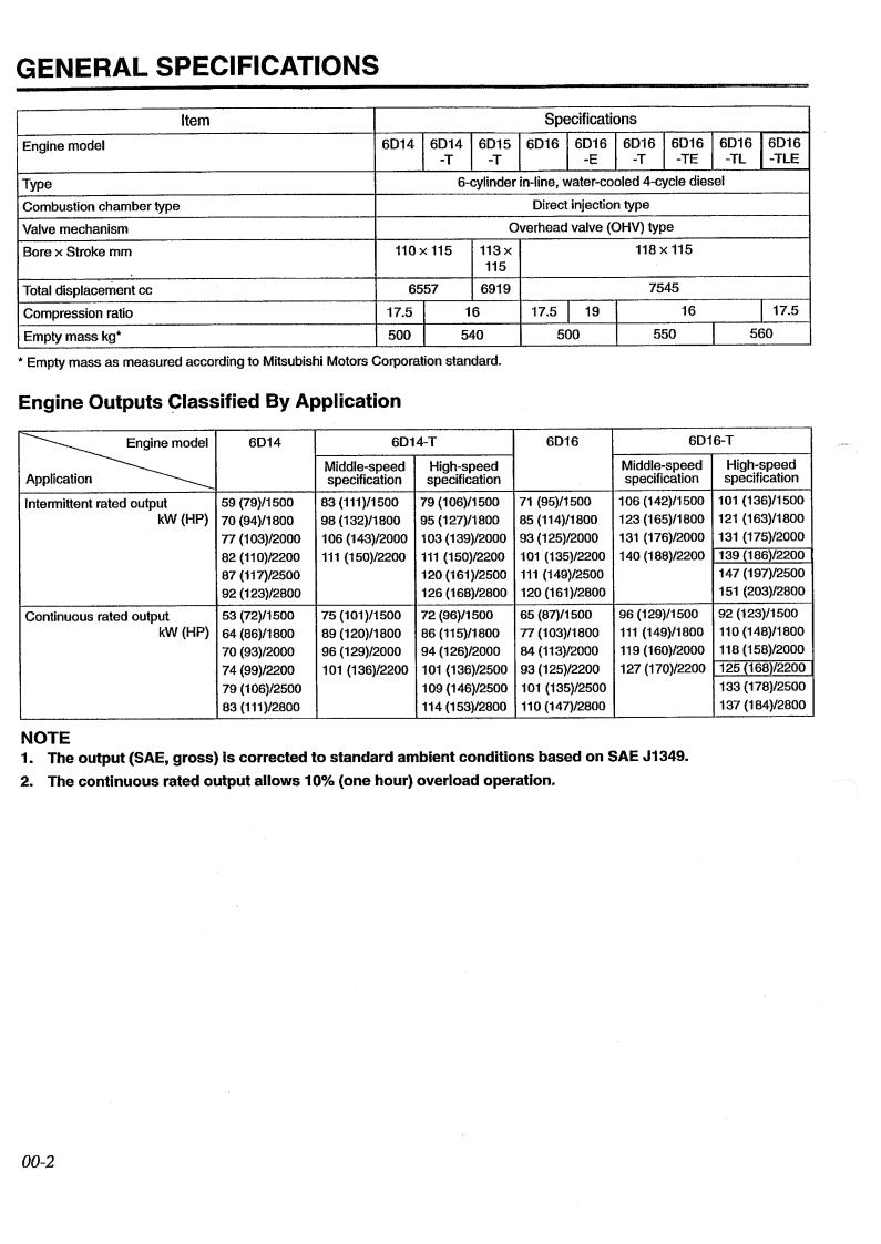
GENERAL SPECIFICATIONS
Item
Specifications
Engine model
Type Combustion chamber type Valve mechanism Bore x Stroke mm
Total displacement cc Compression ratio Empty mass kg*
6014 |
6014 |
6015 |
601616016 |
6016160161601616016 |
||||||
|
-T |
|
-T |
|
|
-E |
-T |
-TE |
-TL |
-TLE |
|
|
6-cylinder in-line, water-cooled 4-cycle diesel |
|
|
||||||
|
|
|
|
Direct injection type |
|
|
|
|||
|
|
|
Overhead valve (OHV) type |
|
|
|
||||
110x115 |
|
113 X |
|
|
|
118x115 |
|
|
||
|
|
|
115 |
|
|
|
|
|
|
|
6557 |
|
6919 |
|
|
|
7545 |
|
|
||
17.5 |
|
|
16 |
17.5 |
1 |
19 |
|
16 |
1 |
17.5 |
|
|
|
I |
|||||||
500 |
|
540 |
500 |
|
550 |
560 |
||||
|
|
|
||||||||
|
|
|
|
|
||||||
*
Empty
mass
as
measured according to Mitsubishi Motors Corporation standard.
Engine
Outputs
~lassified
By
Application
~n Intermittent rated output kW (HP)
Continuous rated output kW (HP)
|
|
6014 |
59 (79)/1500 |
||
70 (94}/1800 |
||
77 |
(1 |
03)/2000 |
82 (110)/2200 |
||
87 (117)/2500 |
||
92 |
(123}/2800 |
|
53 |
(72)/1500 |
|
64 |
(86)/1800 |
|
70 (93}/2000 |
||
74 (99)/2200 |
||
79 |
(106)/2500 |
|
83 {111)/2800 |
||
|
6014-T |
|
|
|
6016 |
|
6016-T |
|
||
|
|
|
|
|
|
|
|
|||
Middle-speed |
High-speed |
|
|
|
Middle-speed |
High-speed |
||||
specification |
specification |
|
|
|
specification |
specification |
||||
83 (111)/1500 |
79 (106)/1500 |
71 |
(95)/1500 |
106 (142)/1500 |
101 |
(136)/1500 |
||||
98 (132)/1800 |
95 (127)/1800 |
85 (114}/1800 |
123 (165)/1 BOO |
121 |
(163}/1800 |
|||||
|
|
|
|
|||||||
106 (143)/2000 |
103 (139)/2000 |
93 (125)/2000 |
131 |
(176}/2000 |
131 |
(175)/2000 |
||||
111 |
(150)/2200 |
111 |
(150)/2200 |
101 |
(135)/2200 |
140 (188)/2200 |
139 (186)/2200 |
|||
|
|
|
|
|||||||
|
|
120 (161)/2500 |
111 |
(149}/2500 |
|
|
147 (197)/2500 |
|||
|
|
|
|
|
|
|||||
|
|
126 (168)/2800 |
120 (161)/2800 |
|
|
151 |
(203}/2800 |
|||
|
|
|
|
|
|
|||||
75 (101)/1500 |
72 (96)/1500 |
65 (87)/1500 |
96 (129)/1500 |
92 (123)/1500 |
||||||
89 (120)/1800 |
86 (115}/1800 |
77 (103)/1800 |
111 |
(149)/1800 |
110 |
(148)/1800 |
||||
96 (129}/2000 |
94 (126)/2000 |
84 (113}/2000 |
119 |
(160}/2000 |
118 |
(158)/2000 |
||||
101 |
(136)/2200 |
101 |
(136)/2500 |
93 (125)/2200 |
127 (170)/2200 |
125 (168)/2200 |
||||
|
|
|||||||||
|
|
109 (146)/2500 |
101 |
(135)/2500 |
|
|
133 {178)/2500 |
|||
|
|
|
|
|
|
|||||
|
|
114 (153)/2800 |
110 |
(147)/2800 |
|
|
137 (184)/2800 |
|||
|
|
|
|
|
|
|||||
NOTE
1. The
output
(SAE,
gross)
Is
corrected
to
standard
ambient
conditions
based
on
SAE J1349.
2.
The
continuous
rated
output
allows
10% {one
hour)
overload operation.
00-2
ENGINE NUMBER AND NAME PLATE
00
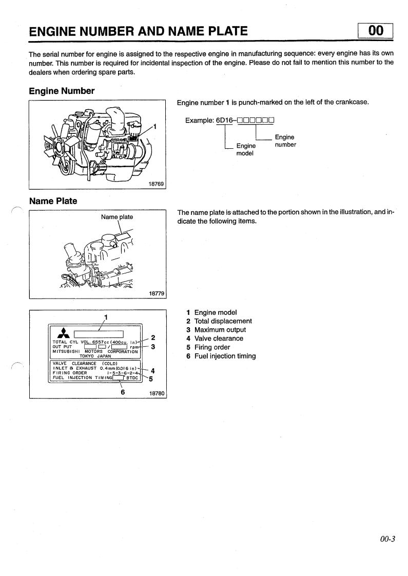
The serial number for engine is assigned to the respective engine in manufacturing |
sequence: every |
|
|
number. This number is required for incidental inspection of the engine. Please do not fail to mention |
|
dealers when ordering spare parts. |
|
engine has its own this number to the
Engine Number
1
Engine number 1 is punch-marked on the left of the crankcase.
Example: 6016-DDDDDD |
|
|
1 |
LEngine |
|
|
||
|
Engine |
number |
|
model |
|
Name Plate
Name plate
The name plate is-attached to the portion shown in the illustration, and indicate the following items.
~ I
|
|
|
|
|
|
|
18779 |
|
|
|
|
1 |
|
|
|
|
|
|
|
I |
|
|
|
AI |
|
I |
I |
|
|
2 |
|
TOTAL CYL VOL. 6557cc (400cu. |
In) |
_.... |
3 |
||||
OUT PUT |
|
c::::::::J CJ ;c=J |
rpm- |
- |
|||
MITSUBISHI |
MOTORS |
CORPORATION |
|
|
|||
|
|
TOKYO |
JAPAN |
|
|
|
|
VALVE |
CLEARANCE |
|
(COLD) |
|
|
4 |
|
INLETS. EXHAUST |
0.4mm(O.OI61n) |
j-- |
|||||
FIRING |
ORDER |
|
1-5-3-6-2-4 |
r---- |
5 |
||
FUEL INJEcTioN TIMINGO;sTDc |
|||||||
|
|
|
|
\ |
|
|
|
|
|
|
|
|
|
|
|
|
|
|
|
6 |
|
|
18780 |
1 2 3 4 5 6
Engine model Total displacement Maximum output Valve clearance Firing order Fuel injection timing
00-3

PRECAUTIONS FOR MAINTENANCE OPERATION
In order to determine the condition of the vehicle adequately, attend the vehicle beforehand to find and keep record of the accumulated mileage, operating condition, what the. customer'sdemand is, and other information that may be necessary. Prepare the steps to be taken and perform efficient and wasteless maintenance procedure.
Determine where the fault exists and check for the cause to see whether removal or disassembly of the part is necessary. Then follow the procedure specified by this manual.
0
18770
Perform maintenance work at a level area.
Prepare the following.
•Prepare general and special tools necessary for the maintenance work.
WARNING& -------------- |
|
|
Do not attempt to use tools other than special tools where use of |
|
special tools is specified in this manual. This will avoid injury or |
|
damage. |
Pay special attention to safety when removing or installing heavy items |
|
such as engines, transmissions. |
|
When lifting up heavy items using cables, pay special attention to the fol- |
|
lowing points: |
|
• |
Check the mass of the item to be lifted and use a cable capable of lifting |
|
that mass. |
14194 |
|
• |
If you do not have the specified lifting hanger, secure the item using |
|
cable taking the point-of-balance of the item into consideration. |
14195
•You must work in a position where you will not be injured even if the cable comes undone and the lifted item falls.
00-4
00
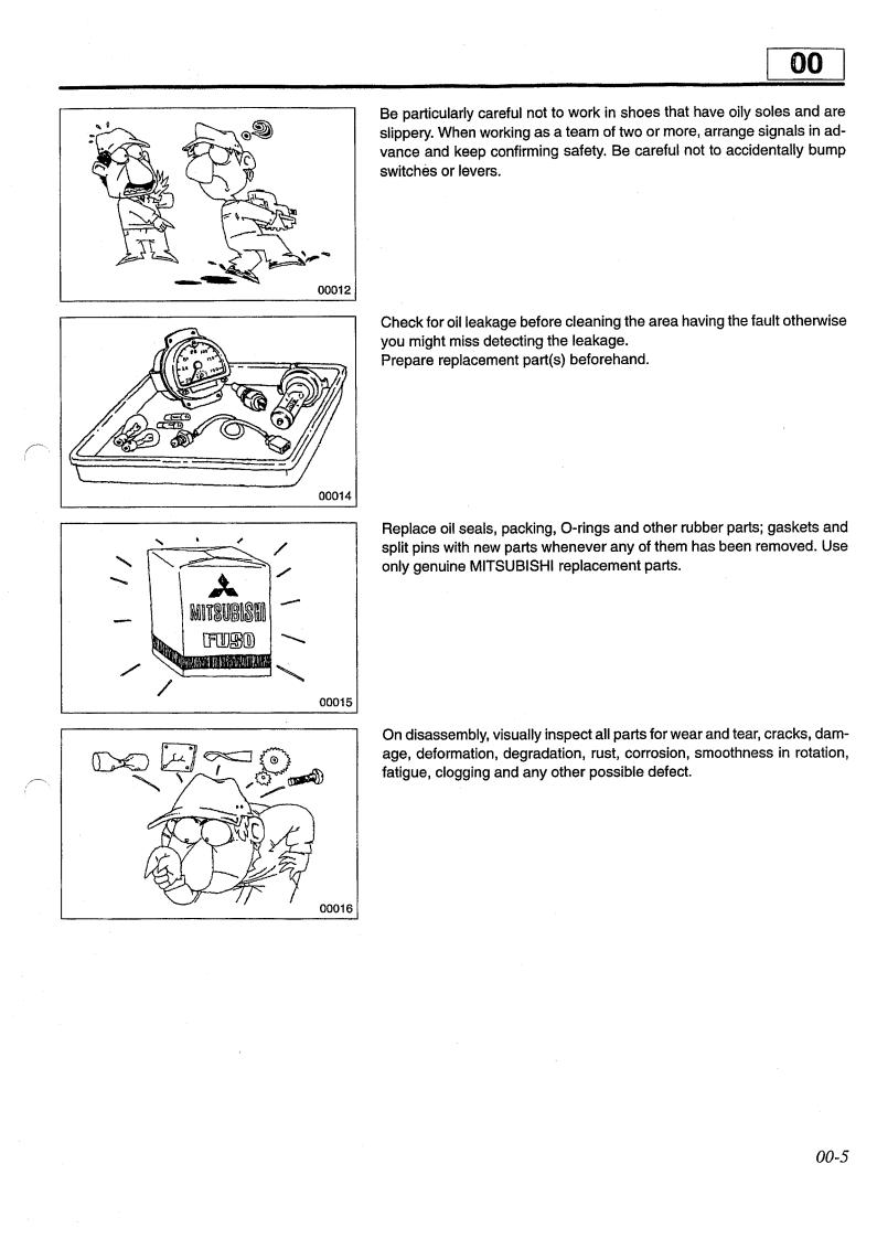
Be particularly careful not to slippery. When working as a vance and keep confirming switches or levers.
work in shoes that have oily soles and are team of two or more, arrange signals in adsafety. Be careful not to accidentally bump
00012
Check for oil leakage before cleaning the area having the fault otherwise you might miss detecting the leakage. Prepare replacement part(s) beforehand.
/~
|
|
|
|
|
00014 |
|
' |
~ |
|
/ |
|
|
|
|
|
||
' |
""- |
;.. |
|
/ |
|
......... |
|
|
|
- |
|
|
|
~~1r~w~~~m~ |
|||
|
|
[f[][J~[[) |
-- |
||
|
|
|
|
||
/ |
/ |
|
|
' |
|
|
|
|
|||
|
|
|
|
00015 |
|
|
|
|
|
|
|
([>C) 8~~ |
|||||
""'\ |
f |
• |
|
~ |
|
|
|
|
"/ |
|
|
Replace oil seals, packing, 0-rings and other rubber parts; gaskets and split pins with new parts whenever any of them has been removed. Use only genuine MITSUBISHI replacement parts.
On disassembly, visually inspect all parts for wear and tear, cracks, damage, deformation, degradation, rust, corrosion, smoothness in rotation, fatigue, clogging and any other possible defect.
00016
00-5

PRECAUTIONS FOR
MAINTENANCE
OPERATION
Put alignment marks on part combinations before disassembly and arrange the disassembled parts neatly. This will help avoid mismating of the parts later. Put the alignment marks, punch marks, etc. where performance and appearance will not be affected. Cover the area left open after removal of parts to keep it free from dust. CAUTION,& . --------------
• •
Take care and right, Keep new arate.
to avoid etc. parts for
mixing up numerous parts, similar parts, left replacement and original (removed) parts sep-
Apply the specified oil or grease to U-packings, oil seals, dust seals and bearings during assembly. Use only the specified oil, grease, etc. for lubricant, remove the excess immediately after application with a piece of waste, etc. CAUTION _ & -------------- When the specified lubricant, fluid and sealant is not available, you may use an equivalent.
00018
Wear goggles when using a grinder or welder. Pay full attention to safety by wearing gloves when necessary. Watch out for sharp edges, etc. that might injure your hands or fingers.
00019
Before carrying out maintenance work on the electric system, disconnect the negative terminals of the batteries to prevent them from short-circuit- ing and burning-out. CAUTION_&-----------------
Be sure to turn starter and lighting switches, connecting or connecting battery terminals, conductors can be damaged.
etc. off before dis because the semi
- -
00-6

00
Take care when .handling sensors, relays, etc. which are vulnerable to shock and heat. Do not attempt to remove the cover from, or apply paint to, the electronic control unit.
Pull the connector, and not the harness lead, to separate connectors. To separate a lock-type connector, first push toward arrow mark. To reconnect a lock-type connector, press the separated parts until they click together.
When washing the vehicle, cover the electric system parts and instruments with waterproof material beforehand (Cover with vinyl sheet or the like). Keep water away from harness wire connectors and sensors. If any of them should get wet, wipe them off immediately.
00023
When using an electric welder, such electronic parts that are directly con- |
|
nected to the batteries might be damaged due to the flow of current from |
|
the welder that flows through the negative circuit. Parts that have switches |
|
might be subject to the same danger if the switches are left on. |
|
Therefore, do not fail to observe the following. |
|
• |
Connect the negative terminal of the welder as near as possible to the |
|
area that is to be welded. |
• |
Disconnect the negative terminals of batteries. |
To apply voltage for testing, check that the positive and negative cables are connected properly, then increase voltage gradually from 0 volt. Do not apply voltage higher than the specified value. In particular, pay close attention to the electronic control unit and sensors, since they are not always fed the battery voltage.
14185
00-7
PRECAUTIONS FOR MAINTENANCE OPERATION
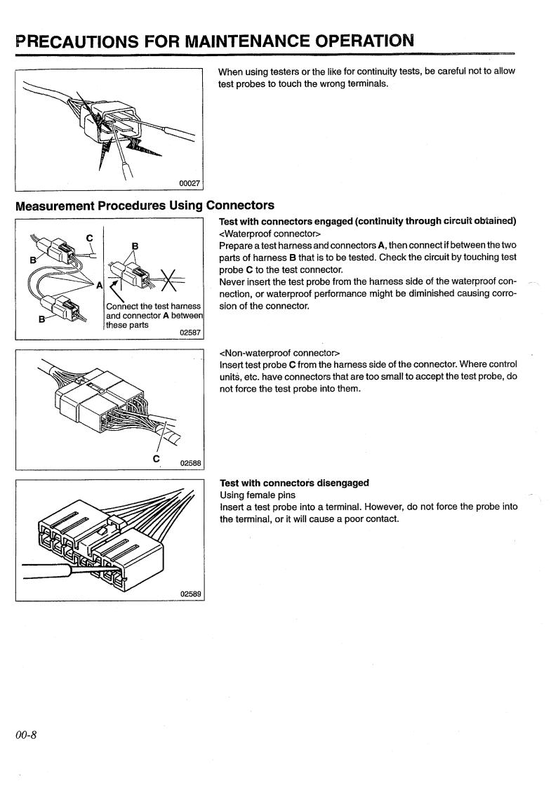
When using testers test probes to touch
or the like for continuity tests, be careful not to allow the wrong terminals.
Measurement Procedures Using Connectors
Test with
connectors engaged (continuity through
circuit
obtained)
<Waterproof connector> Prepare a test harness and connectors A, then connect if between the two parts of harness B that is to be tested. Check the circuit by touching test probe C to the test connector. Never insert the test probe from the harness side of the waterproof connection, or waterproof performance might be diminished causing corrosion of the connector.
02587
<Non-waterproof connector> Insert test probe C from the harness side of the units, etc. have connectors that are too small to not force the test probe into them.
connector. Where control accept the test probe, do
c
02588
Test with connectors disengaged Using female pins Insert a test probe into a terminal. However, do not force the probe into the terminal, or it will cause a poor contact.
00-8

00
Using male pins Touch the pins directly using test probes. CAUTION . &_ --------------
Be sure that you do not short circuit the connector use the test probe because this could damage the of the electronic control unit.
pins when you internal circuit
02590 Connector Inspection Procedures
Visual inspection Check for loose connection and
poor
engagement.
02591
Check if harnesses are broken by pulling gently around the terminals.
Check for a decrease in contact pressure between the male and female terminals.
02593
Check for poor contact caused by connector pins having fallen out, rusted terminals or foreign particles.
00-9

00
•While the engine is running, do not remove the battery terminals. If the battery terminals are removed at that time, a surge voltage is gener-
ated and the
diode or
regulato~
might be weakened.
•Do not use a high-voltage tester such as a megger for inspection. If a high-voltage tester is used, the diode or regulator might be destroyed.
02371
•Do not splash water over the alternator.
If water is directly splashed over the alternator, individual components will be short-circuited and might be destroyed.
05165
•
Do not short-circuit tor. If the terminals are diode trio might be
terminal Band terminal L
short-circuited while the destroyed.
while running the alterna-
alternator is running, the
f
04749
• |
Disconnect the |
battery terminals before quick-charging the battery. |
|
|
Quick-charging |
without disconnecting the battery terminals might |
|
|
damage the diode or regulator. |
· |
|
I
/
05166
00-11


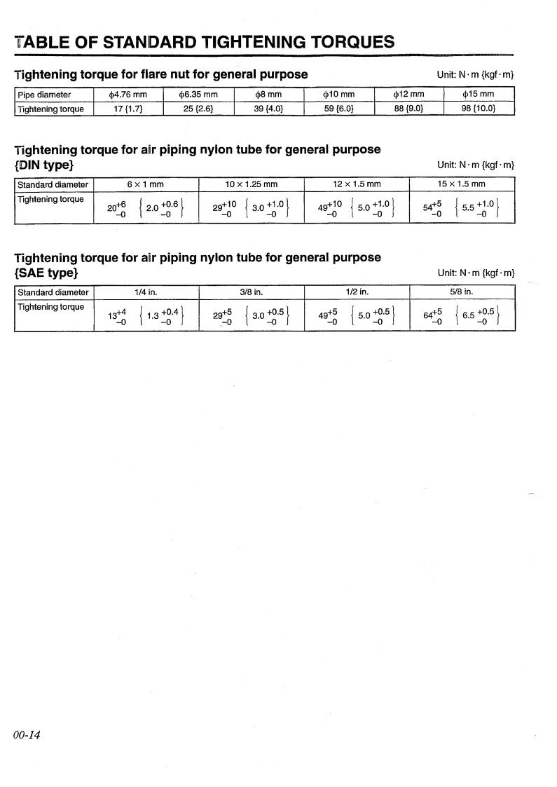
TABLE OF STANDARD TIGHTENING TORQUES |
|||||
Tightening torque for flare nut for general purpose |
|
|
|||
Pipe diameter |
Q>4.76 mm |
<j>6.35 mm |
Q>8mm |
Q>10mm |
Q>12mm |
Tightening torque |
17{1.7} |
25 {2.6} |
39 {4.0} |
59 {6.0} |
88 {9.0} |
Unit: N ·m {kgf ·m}
Q>15mm 98 {10.0}
Tightening torque for anr piping nylon tube for general purpose |
|||||||||
{DIN type} |
|
|
|
|
|
|
|
|
|
Standard diameter |
|
6x1mm |
10 x 1.25 mm |
|
|
12 x 1.5 mm |
|||
Tightening torque |
6 |
{ 2.0 |
~g·6} |
29+10 |
{ 3.0 ~· |
0 |
} |
49+10 |
{ 5.0 ~~.0} |
|
|||||||||
|
2o+ |
|
|
|
|
|
|
||
|
-0 |
|
|
-0 |
|
|
|
-0 |
|
|
Unit: N ·m {kgf ·m} |
||
|
15 x 1.5 mm |
||
54+ |
5 |
{ 5.5 |
~~.0} |
|
|
||
-0 |
|
|
|
Tightening torque for air piping nylon tube for general purpose |
||||||||||||||
{SAE type} |
|
|
|
|
|
|
|
|
|
|
|
|
|
|
Standard diameter |
|
1/4 in. |
|
|
|
3/8 in. |
|
|
|
1/2 in. |
|
|||
Tightening torque |
4 |
{ |
1.3 |
~g.4} |
29+ |
5 |
{ |
3.0 |
~g-5} |
49+ |
5 |
{ |
5.0 |
~g-5} |
|
||||||||||||||
|
13+ |
|
|
|
|
|
|
|
|
|
|
|
||
|
-0 |
|
|
|
-0 |
|
|
|
-0 |
|
|
|
||
|
Unit: N ·m {kgf ·m} |
|||
|
|
5/8 in. |
|
|
64+ |
5 |
{ |
6.5 |
~g-5} |
|
|
|
||
-0 |
|
|
|
|
00-14


STR·UCTURE AND OPERATION
11
1. Cylinder Head and Crankcase <Engines with wet type cylinder liners: 6014, 14-T, 15-T>
1 9
2
1 |
Connecting plate |
2 |
Glow plug |
3 |
Cylinder liner |
4 |
o~ring |
5 |
Crankcase |
6 |
Water jacket |
7 |
Piston |
8 |
Injection nozzle |
9 |
Cylinder head |
A: Cylinder liner size mark: |
|
A,
B, C
•
•
•
A
01924
The cylinde~ liners 3 are a removable wet type liners. They are press-fitted into the top of the crankcase 5 and the bottom of the water jacket 6.
The 0-rings 4 are provided to prevent the ingress of coolant. The cylinder liners 3 and pistons 7 have size marks. The liner and piston that are paired should be of the same size mark.
<Engines with
dry type cylinder liner: 6015-T, 16, 16-E, 16-T, 16-TE, 16-TL,I16-TLEI>
-c--1
/-"-"lt'"H'~-""'~
1 2 3 4 5 6 7 8
Connecting plate Glowplug Cylinder liner Crankcase Water jacket Piston Injection nozzle Cylinder head
7
A
•
•
A: Cylinder liner size mark Outer diameter mark: 1, 2, 3 Inner diameter mark: A, B
The cylinder liners 3 are a dry type liners that are easier to remove than wet liners. Liners are press-fitted into the crankcase 4.
The cylinder liners 3, crankcase 4, and pistons 6 have size marks. They should be combined as specified according to the size marks. CD P.11-28
3
01925
11-3


STRUCTURE AND OPERATION |
|
6. |
Flywheel |
|
1 |
|
I l!!!!l!!lll!!l!l!!!!l 1' |
3
2
|
A |
|
|
|
|
- |
5 |
1 |
|
I |
1 |
|||
l!!!l!l!!!lnnlm!l |
||||
1 2 3
A:
Flywheel
Pilot bearing
Ring gear
Angle scale, cylinder number
01934
7.
Flywheel
PTO
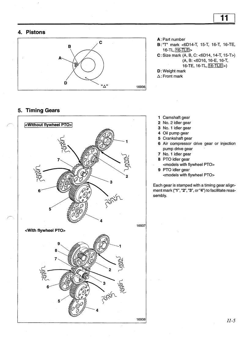
1 2 3 4 5 6 7 8 9
Flange PTO shaft PTO idler shaft Flywheel housing Crank!;lhaft gear No. 1 idler gear PTO idler gear PTO idler gear PTO gear
. The flywheel PTO is fitted onto the top of the flywheel housing 4 and is driven by the crankshaft
gear
5.
01935
11-6
 Loading...