


 Loading...
Introduction of <CNC 70 Series Maintenance Training> Course
Course name |
: CNC 70 |
Series maintenance |
Maximum number |
: 5 |
|
of trainees |
|
|
Aim of the course |
: to learn about maintenance of CNC 70 Series |
|
Intended trainees |
: Engineers in charge of NC machine tool maintenance |
|
Textbook to use |
: CNC 70 |
Series Maintenance Course |
NC model to use |
: CNC 70 |
Series |
Curriculum (One-day course)
Date |
Time |
Contents |
|
|
|
|
|
|
|
( Day |
9:15 |
Orientation |
The entry of |
|
|
participation |
|||
NC system hardware configuration |
||||
to |
||||
|
|
record |
||
|
Maintenance and diagnosis screens |
|||
) |
12:00 |
|||
|
|
|||
Data input/output operation and practice |
|
|||
(Month |
|
|
||
|
|
|
||
|
NC alarms and part replacement practice |
|
||
|
|
|
||
|
13:00 |
|
|
|
|
NC setup and practice |
|
||
|
to |
|
|
|
|
Drive system maintenance and part |
|
||
|
16:30 |
replacement practice |
|
|
|
|
|
|
|
) |
|
Drive system alarms and their remedies |
|
|
|
|
|
|
Preface
This textbook is designed to be used in "CNC 70 Series maintenance training course". Operations and procedures described in this textbook are basically standard ones. Therefore, they
may be different from yours, depending on your NC model, machine tool builder, machine type, and so on. Before you carry out actual maintenance such as part replacement, we recommend you to consult with our service center.
As this textbook has been written based mostly on the following manuals, please refer to them for the details.
• 700/70 Series Instruction Manual.................................................................. |
IB-1500041 |
• 700/70 Series Setup Manual ......................................................................... |
IB-1500123 |
• 70 Series Connection Manual ....................................................................... |
IB-1500253 |
• MDS-D/DH Series Instruction Manual........................................................... |
IB-1500024 |
• MDS-D-SVJ3/SPJ3 Series Instruction Manual.............................................. |
IB-1500192 |
Contents
1. 70 Series System Configuration ......................................................................................................................... |
1 |
1.1 NC Configuration ........................................................................................................................................... |
1 |
1.2 System Configuration .................................................................................................................................... |
2 |
1.2.1 System Basic Configuration Drawing...................................................................................................... |
2 |
1.2.2 General Connection Diagram.................................................................................................................. |
3 |
1.2.3 List of Configuration Units ....................................................................................................................... |
5 |
1.2.3.1 Control Unit: FCU7-MU521/FCU7-MU522........................................................................................ |
5 |
1.2.3.2 Display Unit: FCU7-DU120-12/FCU7-DU140-12/FCU7-DU140-32 ................................................. |
5 |
1.2.3.3 Operation Panel I/O Unit: FCU7-DX7xx............................................................................................ |
6 |
1.2.3.4 Keyboard Unit: FCU7-KB024/ FCU7-KB044 .................................................................................... |
7 |
1.2.3.5 Remote I/O Unit: |
|
FCUA-DX100/FCUA-DX110/FCUA-DX120/FCUA-DX140/FCUA-DX101/FCUA-DX111/ |
|
FCUA-DX121/FCUA-DX141 ......................................................................................................................... |
7 |
1.2.3.6 Scan I/O Card: HR357/HR347.......................................................................................................... |
7 |
1.2.3.7 Card-sized I/O Card: HR361/HR371/HR381/HR383 ........................................................................ |
8 |
1.2.3.8 External Power Supply Unit: PD25/PD27 ......................................................................................... |
8 |
2. Maintenance Screens ......................................................................................................................................... |
9 |
2.1 Input/Output Screen ...................................................................................................................................... |
9 |
2.1.1 Changing the Valid Area........................................................................................................................ |
12 |
2.1.2 Selecting a Device, Directory and File .................................................................................................. |
13 |
2.1.3 Transferring a File ................................................................................................................................. |
20 |
2.1.4 Comparing Files (Compare) .................................................................................................................. |
22 |
2.1.5 Formatting an External Device.............................................................................................................. |
23 |
2.1.6 List of File Names.................................................................................................................................. |
23 |
2.2 All Backup Screen........................................................................................................................................ |
24 |
2.2.1 Performing a Backup Operation............................................................................................................ |
26 |
2.2.2 Performing a Restore Operation ........................................................................................................... |
26 |
2.2.3 Setting Automatic Backup ..................................................................................................................... |
27 |
2.2.4 Backing up the SRAM ........................................................................................................................... |
28 |
2.3 Absolute Position Setting Screen ................................................................................................................ |
30 |
2.3.1 Selecting the Axis .................................................................................................................................. |
32 |
2.3.2 Carrying Out Dogless-type Zero Point Initialization .............................................................................. |
33 |
2.3.3 Carrying Out Dog-type Zero Point Initialization..................................................................................... |
41 |
2.3.4 Precautions............................................................................................................................................ |
41 |
3. Diagnosis Screens ............................................................................................................................................ |
44 |
3.1 System Configuration Screen...................................................................................................................... |
44 |
3.2 Option Display Screen................................................................................................................................. |
47 |
3.3 I/F Diagnosis Screen ................................................................................................................................... |
48 |
3.3.1 Displaying the PLC Device Data ........................................................................................................... |
51 |
3.3.2 Carrying Out Modal Output ................................................................................................................... |
52 |
3.3.3 Carrying Out One-shot Output .............................................................................................................. |
53 |
3.4 Drive Monitor Screen................................................................................................................................... |
54 |
3.4.1 Servo Axis Unit Display Items ............................................................................................................... |
56 |
3.4.2 Spindle Unit Display Items..................................................................................................................... |
59 |
3.4.3 Display Items for the Power Supply Unit............................................................................................... |
68 |
3.4.4 Display Items for the Synchronous Error .............................................................................................. |
70 |
3.4.5 Clearing the Alarm History..................................................................................................................... |
71 |
3.5 NC Memory Diagnosis Screen (NC Memory Diagn Screen) ...................................................................... |
72 |
3.5.1 Writing/Reading the Data Using the NC Data Designation ................................................................... |
74 |
3.6 Alarm Screen ............................................................................................................................................... |
75 |
3.6.1 Alarm History ......................................................................................................................................... |
77 |
3.7 Self Diagnosis Screen ................................................................................................................................. |
79 |
4. NC's Maintenance Check and Replacement Procedure .................................................................................. |
83 |
4.1 Maintenance Items ...................................................................................................................................... |
83 |
4.1.1 Escutcheon............................................................................................................................................ |
83 |
4.1.2 LCD Panel ............................................................................................................................................. |
84 |
4.1.3 Compact Flash/IC card.......................................................................................................................... |
84 |
4.2. H/W Replacement Methods........................................................................................................................ |
85 |
4.2.1 Durable Parts......................................................................................................................................... |
85 |
4.2.1.1 Control unit battery.......................................................................................................................... |
85 |
4.2.1.2 Backlight.......................................................................................................................................... |
87 |
4.2.2 Unit ........................................................................................................................................................ |
89 |
4.2.2.1 Control Unit ..................................................................................................................................... |
89 |
4.2.2.2 Display Unit ..................................................................................................................................... |
91 |
4.2.2.3 Keyboard unit .................................................................................................................................. |
92 |
4.2.2.4 DX Unit............................................................................................................................................ |
94 |
4.2.3 Compact Flash ...................................................................................................................................... |
95 |
4.2.3.1 Front Compact Flash....................................................................................................................... |
95 |
5. NC Setup Procedures ....................................................................................................................................... |
96 |
5.1 Setup Procedure after SRAM Clear ............................................................................................................ |
96 |
5.1.1 Outline of Hardware Configuration........................................................................................................ |
96 |
5.1.2 Outline of Setup Procedures ................................................................................................................. |
97 |
5.2 Setup Details ............................................................................................................................................... |
99 |
5.2.1 Erasing the backed up data (SRAM)..................................................................................................... |
99 |
5.2.2 Inputting the Parameters ..................................................................................................................... |
100 |
5.2.2.1 When There is No Parameter File ................................................................................................ |
100 |
5.2.2.2 When a Parameter File is Available .............................................................................................. |
101 |
5.2.2.3 Parameter Screens ....................................................................................................................... |
102 |
5.2.3 Formatting the File System ................................................................................................................. |
113 |
5.2.4 Integrated Time Display....................................................................................................................... |
114 |
5.2.4.1 Setting the Integrated Time........................................................................................................... |
115 |
5.2.4.2 Setting the Time Display Selection ............................................................................................... |
116 |
5.2.5 Credit System...................................................................................................................................... |
117 |
5.2.6 Absolute Position Detection System ................................................................................................... |
119 |
5.2.6.1 Dog-type Reference Position Return Operation ........................................................................... |
119 |
5.2.6.2 Starting up the Absolute Position Detection System..................................................................... |
120 |
5.2.7 PLC Switch Function ........................................................................................................................... |
122 |
5.2.7.1 Turning PLC Switches ON/OFF .................................................................................................... |
123 |
5.3 7-segment LED's Alarm/Status Indication ................................................................................................. |
124 |
5.3.1 Outline ................................................................................................................................................. |
124 |
5.3.2 Status Display...................................................................................................................................... |
124 |
5.3.3 Alarm Display ...................................................................................................................................... |
124 |
5.3.4 Notes ................................................................................................................................................... |
125 |
5.3.5 Example of alarm display .................................................................................................................... |
126 |
6. Drive Unit Maintenance................................................................................................................................... |
134 |
6.1 MDS-D/DH Series...................................................................................................................................... |
134 |
6.1.1 Part system connection diagram......................................................................................................... |
134 |
6.1.2 Maintenance........................................................................................................................................ |
135 |
6.1.2.1 Inspections .................................................................................................................................... |
135 |
6.1.2.2 Service parts ................................................................................................................................. |
135 |
6.1.2.3 Adding and replacing units and parts............................................................................................ |
136 |
6.1.2.3.1 Replacing the drive unit .......................................................................................................... |
136 |
6.1.2.3.2 Replacing the unit fan ............................................................................................................. |
137 |
6.1.2.3.3 Replacing the battery.............................................................................................................. |
138 |
6.1.2.3.4 Replacing the fuse .................................................................................................................. |
140 |
6.2 MDS-D-SVJ3/SPJ3 Series ........................................................................................................................ |
141 |
6.2.1 Part system connection diagram......................................................................................................... |
141 |
6.2.2 Maintenance........................................................................................................................................ |
142 |
6.2.2.1 Inspections .................................................................................................................................... |
142 |
6.2.2.2 Service parts ................................................................................................................................. |
142 |
6.2.2.3 Adding and replacing units and parts............................................................................................ |
143 |
6.2.2.3.1 Replacing the drive unit .......................................................................................................... |
143 |
6.2.2.3.2 Replacing the unit fan ............................................................................................................. |
144 |
6.2.2.3.3 Replacing the battery.............................................................................................................. |
145 |
7. Servo System Maintenance............................................................................................................................ |
146 |
7.1 D/A output specifications for servo drive unit ............................................................................................ |
146 |
7.1.1 MDS-D/DH Series ............................................................................................................................... |
146 |
7.1.1.1 |
D/A output specifications ............................................................................................................... |
146 |
7.1.1.2 |
Setting the output data .................................................................................................................. |
147 |
7.1.1.3 Setting the output magnification.................................................................................................... |
148 |
|
7.1.2 MDS-D-SVJ3 Series............................................................................................................................ |
149 |
|
7.1.2.1 D/A output specifications............................................................................................................... |
149 |
|
7.1.2.2 Setting the output data .................................................................................................................. |
150 |
|
7.1.2.3 Setting the output magnification.................................................................................................... |
151 |
|
7.2 Vibration Suppression................................................................................................................................ |
152 |
|
7.2.1 Notch filte............................................................................................................................................. |
152 |
|
8. Spindle System Maintenance ......................................................................................................................... |
153 |
|
8.1 D/A output specifications for spindle drive unit.......................................................................................... |
153 |
|
8.1.1 MDS-D/DH Series ............................................................................................................................... |
153 |
|
8.1.1.1 D/A output specifications............................................................................................................... |
153 |
|
8.1.1.2 Setting the output data .................................................................................................................. |
154 |
|
8.1.1.3 Setting the output magnification.................................................................................................... |
156 |
|
8.1.2 MDS-SPJ3 Series ............................................................................................................................... |
157 |
|
8.1.2.1 D/A output specifications............................................................................................................... |
157 |
|
8.1.2.2 Setting the output data .................................................................................................................. |
158 |
|
8.1.2.3 Setting the output magnification.................................................................................................... |
160 |
|
8.2 Diagnostic Procedure When Vibration/Noise Occurs................................................................................ |
161 |
|
8.2.1 How to judge whether the cause is on machine side or control unit side ........................................... |
161 |
|
8.2.2 How to judge PLG trouble ................................................................................................................... |
161 |
|
8.2.3 How to check PLG waveform.............................................................................................................. |
162 |
|
8.2.3.1 Configuration of serial detector TS5691 ....................................................................................... |
162 |
|
8.2.3.2 Adjust A and B phase signals........................................................................................................ |
163 |
|
8.2.3.3 Check Z phase signal.................................................................................................................... |
164 |
|
8.3 Adjustment of Orientation Stop Position .................................................................................................... |
166 |
|
9. Servo/Spindle's Troubleshooting..................................................................................................................... |
167 |
|
9.1 MDS-D/DH Series...................................................................................................................................... |
167 |
|
9.1.1 Points of caution and confirmation ...................................................................................................... |
167 |
|
9.1.1.1 LED display when alarm or warning occurs.................................................................................. |
168 |
|
9.1.2 Protective functions list of units ........................................................................................................... |
169 |
|
9.1.2.1 List of alarms................................................................................................................................. |
169 |
|
9.1.2.2 List of warnings ............................................................................................................................. |
173 |
|
9.1.3 Troubleshooting................................................................................................................................... |
176 |
|
9.1.3.1 Troubleshooting at power ON ....................................................................................................... |
176 |
|
9.1.3.2 Troubleshooting for each alarm No............................................................................................... |
177 |
|
9.1.3.3 Troubleshooting for each warning No. .......................................................................................... |
200 |
|
9.1.3.4 Parameter numbers during initial parameter error........................................................................ |
202 |
|
9.1.3.5 Troubleshooting the spindle system when there is no alarm or warning ...................................... |
203 |
|
9.2 MDS-D-SVJ3/SPJ3 Series ........................................................................................................................ |
205 |
|
9.2.1 Points of caution and confirmation ...................................................................................................... |
205 |
|
9.2.1.1 LED display when alarm or warning occurs.................................................................................. |
206 |
|
9.2.2 Protective functions list of units ........................................................................................................... |
207 |
|
9.2.2.1 List of alarms................................................................................................................................. |
207 |
|
9.2.2.2 List of warnings ............................................................................................................................. |
210 |
|
9.2.3 Troubleshooting................................................................................................................................... |
213 |
|
9.2.3.1 Troubleshooting at power ON ....................................................................................................... |
213 |
|
9.2.3.2 Troubleshooting for each alarm No............................................................................................... |
214 |
|
9.2.3.3 Troubleshooting for each warning No. .......................................................................................... |
232 |
|
9.2.3.4 Parameter numbers during initial parameter error........................................................................ |
234 |
|
9.2.3.5 Troubleshooting the spindle system when there is no alarm or warning ...................................... |
235 |
|
10. Appendix |
....................................................................................................................................................... |
237 |
10.1 List of Alarms ........................................................................................................................................... |
237 |
|
10.1.1 Operation ...............................................................................................................................Alarms |
237 |
|
10.1.2 Stop ........................................................................................................................................Codes |
245 |
|
10.1.3 Servo/Spindle ........................................................................................................................Alarms |
249 |
|
10.1.4 MCP ........................................................................................................................................Alarm |
258 |
|
10.1.5 System ..................................................................................................................................Alarms |
268 |
|
10.1.6 Absolute .....................................................................................Position Detection System Alarms |
274 |
|
10.1.7 Distance ...........................................................................................-coded Reference Scale Errors |
277 |
|
10.1.8 Messages during Emergency Stop ................................................................................................... |
278 |
10.1.9 Computer Link Errors ........................................................................................................................ |
280 |
10.1.10 User PLC Alarms............................................................................................................................. |
281 |
10.1.11 Network Service Errors.................................................................................................................... |
283 |
10.2 RS-232C I/O Device Parameter Setting Examples ................................................................................. |
284 |
1. 70 Series System Configuration
1.1 NC Configuration
1. 70 Series System Configuration
1.1 NC Configuration
70 Series configuration
|
System model |
Display |
Control unit |
Display unit name |
Machine |
System # |
|
name |
size |
name |
type |
||
|
|
|
||||
|
|
|
|
|
|
|
|
FCA70P-2A |
8.4" LCD |
|
FCU7-DU120-12 |
|
|
MITSUBISHI CNC 70 |
|
|
FCU7-MU522 |
|
|
|
FCA70P-4A |
10.4" LCD |
FCU7-DU140-12 |
|
|
||
Type A |
|
|
||||
|
|
|
|
|
|
|
|
FCA70H-4A |
10.4" LCD |
|
FCU7-DU140-32 |
Common |
BND- |
|
|
|
|
|
to M/L |
1009W000 |
|
FCA70P-2B |
8.4" LCD |
|
FCU7-DU120-12 |
||
|
|
|
|
|||
MITSUBISHI CNC 70 |
|
|
FCU7-MU521 |
|
|
|
FCA70P-4B |
10.4" LCD |
FCU7-DU140-12 |
|
|
||
Type B |
|
|
||||
|
|
|
|
|
|
|
|
FCA70H-4B |
10.4" LCD |
|
FCU7-DU140-32 |
|
|
|
|
|
|
|
|
|
F 
 C
C 
 A
A 
 7
7 
 0
0 
 P 4
P 4 
 A
A
Code |
Hardware type |
P |
Panel-in type (without touch panel specification) |
H |
Panel-in type (with touch panel specification)* |
Code Display unit size
2 8.4 inch
4 10.4 inch
Code Type
AType A
BType B
|
|
* Reserved for future expansion |
|
FCA70 |
M70 Series |
||
|
|||
There are six types of M70 H/W configurations |
|||
1
1. 70 Series System Configuration
1.2 System Configuration
1.2 System Configuration
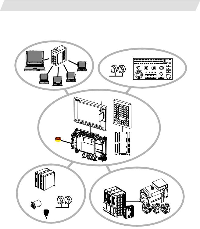
1.2.1 System Basic Configuration Drawing
Ethernet |
hub
Personal computer
Manual pulse |
Machine operation panel |
||||||||||||||
TF |
T CODE DA TA |
|
SFLED29LED30 LED31LED32LED33LED34LED35LED36 |
|
ON |
||||||||||
generator |
MF |
M CODE DATA |
|
AL1 AL2 AL3 |
AL4 |
TAP DEN |
OP SA |
MA |
DEGITAL SWITCH |
||||||
|
|
|
|
|
|
|
|
|
|
|
|
|
RESET |
FIN |
|
|
SW1 SW2 SW3 SW4 SW5 SW6 SW7 SW8 SW9 SW10 SW11 SW12 SW13 OVSL OVC SRN F1D |
OFF |
|||||||||||||
|
|
||||||||||||||
|
HANDLE/STEPMULTIPLICATION |
MODE SELECT |
|
MANUAL FEED RATE |
CUTTINGFEEDRATEOVERRIDE |
|
|
||||||||
|
100 |
1000 5000 |
STEP |
RAPID |
R-POINTRETURN2002705207201000 |
8090100110120 |
|
|
|||||||
|
10 |
10000 |
X |
|
JOG |
|
100 |
|
1400 |
70 |
|
|
130 |
|
|
|
|
|
52 |
|
2000 |
60 |
|
|
140 |
MACHINELOCK MSTLOCK |
|||||
|
|
100000HANDLE |
Z |
|
MDI |
|
27 |
|
2700 |
50 |
|
|
150 |
||
|
|
|
|
2 |
|
7200 |
20 |
|
|
180 |
|
|
|||
|
1 |
50000 |
Y |
|
MEM |
20 |
|
3700 |
40 |
|
|
160 |
|
|
|
|
|
|
|
|
|
|
10 |
|
5200 |
30 |
|
|
170 |
|
|
|
|
|
4 |
|
TAPE |
1 |
|
10000 |
10 |
0 |
% |
190 |
SINGLEBLOCK DRYRUN |
||
|
|
|
|
|
0mm/min14000 |
|
200 |
||||||||
|
- |
+ |
|
|
1STREFERENCEPOSITION |
|
RAPIDTRAVERSEOVERRIDE |
|
|
||||||
|
|
|
|
REACHED |
|
|
|
|
|||||||
|
|
|
|
X |
Y |
|
Z |
4 |
50 |
100 |
|
|
|
||
|
|
|
|
+X |
+Y |
|
+Z |
+4 |
25 |
|
|
|
EMERGENCYSTOP |
||
|
|
|
|
|
1 |
|
|
|
|
|
|||||
|
|
|
|
-X |
-Y |
|
-Z |
-4 |
CYCLESTART |
FEEDHOLD |
|
|
|||
CF card I/F
Display unit
Keyboard unit
Control unit
Operation panel
 I/O unit Emergency
stop switch
|
Remote I/O |
Servo/Spindle drive units |
|
unit |
MDS-D/DH Series |
|
|
MDS-D-SVJ3/SPJ3 Series |
|
Manual pulse |
|
Synchronous feed |
generator |
|
encoder |
|
|
|
Skip |
Motors |
|
|
(Note 1) Control unit is mounted on the back side of the display unit.
(Note 2) Operation panel I/O unit is mounted on the back side of the keyboard unit.
2
1. 70 Series System Configuration
1.2 System Configuration
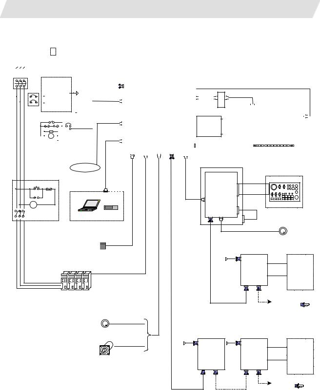
1.2.2General Connection Diagram
(1)Without Touch Panel
Dotted lines indicate the sections prepared by machine tool builder.
The name with brackets <> indicates the cable for the unit.
R S T
|
|
No-fuse breaker(NFB |
|
|
|
|
|
CNC control unit |
|
|
|
|
|
|
|
|
|
|
|
|
|
|
|
|
|
|
|
|
|
|
|
|
|
|
|
|
|
|||||||||||||||||||||
|
|
|
|
|
|
|
FCU7-MU521/522 |
|
|
|
|
|
|
|
|
|
|
|
|
|
|
|
|
|
|
|
|
|
|
|
|
|
|
|
|
|
||||||||||||||||||||||
|
|
|
|
|
|
|
24VDC |
|
|
|
|
|
|
|
|
|
|
|
|
|
|
|
|
|
|
|
|
|
|
|
|
|
|
|
|
|
|
|
|
|
|
|||||||||||||||||
|
|
|
|
|
|
|
|
F070 |
|
|
|
|
|
|
|
|
|
|
|
|
|
|
|
|
|
|
|
<8.4-type: G097> |
|
|
|
|
|
|
|
|
|
|
|
|
|
|
||||||||||||||||
|
|
|
|
|
|
stabilized power |
|
|
|
|
DCIN |
|
|
|
|
|
|
|
|
|
|
|
|
|
|
|
|
|
|
|
|
|
|
|
|
|
|
|
|
|
||||||||||||||||||
|
|
|
|
|
|
|
supply |
24VDC |
|
|
|
|
|
Main card HN76x |
|
|
|
LCD |
|
|
<10.4-type: G098> |
|
|
|
|
|
|
|
|
|||||||||||||||||||||||||||||
|
|
|
|
|
|
|
|
|
DCOUT |
|
|
|
|
|
|
|
|
|
|
|
|
|
<F480> |
|
|
|
|
|
<10.4-type: G482> |
|
|
|
|
|
|
|
|
|||||||||||||||||||||
|
|
|
|
|
|
ACIN |
|
|
F120 |
|
EMG |
|
|
|
|
INV |
|
|
|
|
|
|
|
|
|
|
|
|
|
|
|
|||||||||||||||||||||||||||
|
|
|
|
|
|
|
|
|
|
|
|
|
|
|
|
|
|
|
|
|
|
|
|
|
|
|
|
|||||||||||||||||||||||||||||||
|
|
|
|
|
|
|
|
|
|
FG |
|
|
|
|
|
|
|
|
|
|
|
|
|
|
|
|
|
|
|
|
|
|
|
|
|
|
|
|
|
|
|
|
|
|
|
|
|
|||||||||||
|
|
NFB |
|
|
|
|
|
|
|
|
|
|
|
|
|
|
|
|
|
|
|
Memory card |
|
|
|
|
|
|
|
|
|
Backlight inverter |
|
|
|
|
|
|
|
|
|
|
|
|
|
|||||||||||||
|
|
|
|
|
|
|
|
|
|
|
|
|
|
|
|
|
|
|
|
|
|
|
|
|
|
|
HN4xx |
|
|
|
|
|
|
|
|
|
|
|
|
|
|
|
|
|
|
|
|
|||||||||||
|
|
|
OT release switchEMG |
FG |
|
|
|
|
|
|
|
|
|
|
|
|
Display unit |
|
|
|
|
|
|
|
|
|||||||||||||||||||||||||||||||||
|
|
|
|
G300/G301 |
|
LAN |
|
|
|
|
Expansion |
|
|
FRONT |
|
|
Front CF |
|
|
|
|
|
|
|
8.4-type FCU7-DU120-12 |
|
|
|
|
|
|
|
|
|||||||||||||||||||||||||
|
|
|
|
|
|
|
|
|
|
|
|
|
|
|
|
|
|
|
|
|
|
|
|
|
|
|
|
|
|
card |
|
|
|
|
|
|
|
|
|
10.4-type FCU7-DU140-12 |
|
|
|
|
|
|
|
|
||||||||||
|
|
|
|
|
|
|
|
|
|
|
|
|
|
|
|
|
|
|
|
|
|
|
|
|
|
|
card |
|
|
|
|
|
|
|
|
|
|
|
|
|
|
|
|
|
|
|
|
|
|
|
|
|
||||||
|
|
|
|
|
|
|
|
|
|
|
|
|
|
|
|
|
|
|
|
|
|
|
|
|
|
|
|
|
|
|
|
|
|
|
|
HN791 |
|
|
|
|
|
|
|
|
|
|
|
|
|
|
|
|
|
|
||||
|
|
|
|
|
|
|
RA |
|
|
|
|
|
FG |
|
|
|
|
|
SIO |
|
|
|
|
HN75x |
|
|
MENU |
|
|
|
|
|
|
|
|
|
(VGA:640×480) |
|
|
|
|
|
|
|
|
|||||||||||||
|
|
|
|
|
|
|
|
|
|
|
|
|
|
|
|
|
|
|
|
|
|
|
|
|
|
|
|
|
|
|
|
|
|
|
|
|
|
|
|
|
|
|
|
|
|
|
|
|
||||||||||
|
|
|
|
|
|
|
|
|
|
|
|
|
|
|
|
|
|
|
|
|
|
|
|
|
|
|
|
|
|
|
|
|
|
|
|
|
|
|
|
|
|
|
|
|
|
|
|
|
|
|
|
|
|
|||||
|
|
|
|
|
|
|
|
|
|
|
|
|
|
|
|
|
|
|
|
|
|
SKIP |
OPT ENC RIO1 |
CG71 |
|
|
|
|
|
|
|
|
|
|
|
|
|
|
Menu key |
|
|
|
|
|
|
|
|
|||||||||||
|
|
|
|
|
|
|
|
|
|
|
|
|
|
|
|
|
|
|
|
|
|
|
|
|
|
|
|
|
|
|
|
|
|
|
|
|
|
|
|
|
|
|
|
|
|
|
|
|
|
|
|
|
|
|
|
|
|
|
|
|
|
|
|
|
|
|
|
|
|
|
|
|
|
|
|
|
|
|
|
|
|
|
|
|
|
|
|
|
|
|
|
|
|
|
|
|
|
|
|
|
|
|
|
|
|
|
|
|
|
|
|
|
|
|
|
|
|
|
|
|
Keyboard unit |
|
|
|
|
Network |
|
FCU7-KB024/44 |
|
|
|
|
|
|
|
|
|
|
|
|
|
Operation panel |
Machine operation panel |
||
ON |
OFF |
USER 2ch |
I/O unit |
|||
1ch: F034 |
FCU7-DXxxx |
|
|
|
||
|
|
2ch: F035 |
|
|
|
|
MC |
|
CG3 |
|
|
|
|
RS232C Device |
F351 |
|
|
|||
|
G011 |
|
|
|||
|
|
|
CG71 |
|
|
|
MC |
|
|
max. 0.5m |
|
|
|
|
|
NCKB |
<G402> |
|
|
|
|
|
|
|
|
||
MC |
|
|
|
|
|
|
|
|
RIO3 MPG |
|
|
|
|
|
|
|
|
|
Manual pulse generator |
|
|
|
|
|
12V:F320/F321 |
2ch |
|
|
Skip signal input |
|
|
|
||
|
|
5V:F023/F024 |
|
|
||
|
Sensor signals |
FCUA-R030 |
|
|
|
|
|
Max. 8 pints |
|
|
Remote I/O unit |
|
|
|
|
|
|
|
|
|
|
|
|
24VDC |
DCIN |
|
|
|
|
|
F070 |
|
|
|
|
|
|
FCUA-DX1xx |
|
Machine |
|
|
|
|
|
|
||
|
1ch |
G395/G396/G380 |
|
|
|
|
|
|
DI-L/R |
|
control |
||
|
|
|
|
|
R300 |
relay/contact |
|
|
|
|
RIO1 RIO2 |
|
|
|
|
|
|
|
|
|
|
Spindle/Servo Drive Units |
|
FCUA-R211 |
|
To the next remote |
|
|
|
/SH41 |
|
|||
|
MDS-D/DH/SVJ3/SPJ3 |
|
|
|||
|
|
|
I/O or terminator |
|||
|
|
|
|
|||
|
|
|
|
|
||
Manual pulse generator |
|
|
|
|
|
2ch |
|
|
|
|
|
5V:G023/G024 |
|
|
|
|
|
|
|
Remote I/O unit |
Remote I/O unit |
|
|
Sync. Encoder |
24VDC |
|
24VDC |
|
|
1ch |
|
DCIN |
DCIN |
|
|
FCUA-R050/054 |
F070 |
FCUA-DX1xx |
F070 |
|
Machine |
|
|
FCUA-DX1xx |
|
||
|
|
|
DI-L/R |
|
control |
|
|
|
R300 |
relay/contact |
|
|
|
|
|
||
|
|
RIO1 RIO2 |
RIO1 RIO2 |
|
|
|
|
|
|
||
|
FCUA-R211 |
FCUA-R211 |
To the next remote I/O |
||
|
or terminator |
||||
|
/SH41 |
/SH41 |
|||
|
|
|
|||
3
1. 70 Series System Configuration
1.2 System Configuration
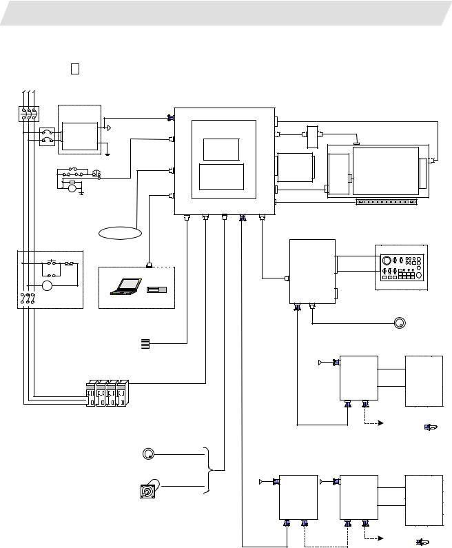
(2) With Touch Panel
Dotted lines indicate the sections prepared by machine tool builder.
The name with brackets <> indicates the cable for the unit.
R S T
No-fuse breaker(NFB |
|
|
CNC control unit |
|
|
|
|
||
|
|
FCU7-MU521/522 |
|
|
|
|
|||
24VDC |
|
|
|
|
|
|
|||
|
F070 |
|
|
|
|
|
|
||
stabilized power |
|
DCIN |
|
|
<G098> |
|
|
||
supply |
|
|
|
LCD |
|
|
|
||
|
|
|
Main card HN76x |
|
|
|
|||
|
|
24VDC |
|
|
|
|
|
||
|
DCOUT |
|
|
INV |
<F480> |
<G482> |
|
||
ACIN |
|
F120 |
|
|
|
||||
|
|
EMG |
|
Backlight |
|
|
|||
FG |
|
|
|
|
|
||||
|
|
|
Memory card |
|
|
|
|||
NFB |
|
|
|
|
inverter |
|
|
||
|
|
|
|
|
|
|
|||
|
|
|
|
HN4xx |
|
|
|
|
|
|
|
FG |
|
|
|
Front CF |
HN244 |
|
|
OT release switchEMG |
|
|
|
FRONT |
Touch panel display unit |
||||
|
G300/G301 |
LAN |
Expansion |
card |
|
||||
|
|
|
|
|
HN791 |
|
FCU7-DU140-32 |
||
|
|
|
|
|
card |
|
TPIN |
|
|
|
|
|
|
|
|
|
|
||
|
|
|
|
|
HN75x |
|
|
|
|
|
|
|
|
|
|
|
TESTIN |
(VGA:640×480) |
|
RA |
|
|
|
|
|
TEST |
|
||
FG |
|
|
SIO |
|
<G422> |
|
|||
|
|
|
|
|
|
|
|||
|
|
|
|
|
|
|
|
||
|
|
|
|
|
MENU |
|
|
|
|
|
|
|
|
|
|
|
|
|
|
|
|
|
|
SKIP |
OPT ENC RIO1 |
CG71 |
|
|
Menu key |
|
|
Network |
|
|
|
|
|
Operation panel |
Machine operation panel |
ON |
OFF |
USER 2ch |
I/O unit |
|
1ch: F034 |
FCU7-DXxxx |
|
||
|
|
2ch: F035 |
|
|
MC |
|
CG3 |
|
|
|
RS232C Device |
F351 |
||
|
|
G011 |
||
|
|
|
CG71 |
|
MC |
|
|
max. 0.5m |
|
|
|
NCKB |
|
|
|
|
|
|
MC |
|
|
RIO3 MPG |
|
|
|
|
|
|
|
|
Manual pulse generator |
|
|
|
|
|
12V:F320/F321 |
2ch |
|
Skip signal input |
|
|
|
|
||
|
|
5V:F023/F024 |
|
|
||
Sensor signals |
FCUA-R030 |
|
|
|
|
|
Max. 8 pints |
|
|
|
Remote I/O unit |
|
|
|
|
|
|
|
|
|
|
|
|
24VDC |
DCIN |
|
|
|
|
|
F070 |
|
|
|
|
|
|
FCUA-DX1xx |
|
Machine |
|
|
|
|
|
|
||
1ch |
G395/G396/G380 |
|
|
|
|
|
|
|
DI-L/R |
|
control |
||
|
|
|
|
|
R300 |
relay/contact |
|
|
|
|
RIO1 RIO2 |
|
|
|
|
|
|
|
|
|
Spindle/Servo Drive Units |
|
|
FCUA-R211 |
|
To the next remote |
|
|
|
/SH41 |
|
|||
MDS-D/DH/SVJ3/SPJ3 |
|
|
|
|||
|
|
|
I/O or terminator |
|||
|
|
|
|
|||
|
|
|
|
|
||
Manual pulse generator |
|
|
|
|
|
|
|
2ch |
|
|
|
|
|
|
5V:G023/G024 |
|
|
|
|
|
|
|
|
Remote I/O unit |
Remote I/O unit |
|
|
Sync. Encoder |
24VDC |
24VDC |
DCIN |
|
|
|
|
1ch |
|
DCIN |
|
|
|
|
FCUA-R050/054 |
F070 |
F070 |
FCUA-DX1xx |
|
Machine |
|
|
|
FCUA-DX1xx |
|
||
|
|
|
|
DI-L/R |
|
control |
|
|
|
|
R300 |
relay/contact |
|
|
|
|
|
|
||
|
|
|
RIO1 RIO2 |
RIO1 RIO2 |
|
|
|
|
|
|
|
||
|
|
FCUA-R211 |
FCUA-R211 |
To the next remote I/O |
||
|
|
or terminator |
||||
|
|
/SH41 |
/SH41 |
|
||
|
|
|
|
|
||
4

1. 70 Series System Configuration
1.2 System Configuration
1.2.3 List of Configuration Units
1.2.3.1 Control Unit: FCU7-MU521/FCU7-MU522
Type |
Function |
Configuration element |
Details |
FCU7-MU521 |
NC functions and |
Main control card (HN761) |
Export Trade Control Ordinance |
|
display controller |
Memory card (HN451) |
and Foreign Trade Ordinance |
|
|
CF I/F Card (HN791) |
noncompliant unit |
FCU7-MU522 |
NC functions and |
Main control card (HN761) |
Export Trade Control Ordinance |
|
display controller |
Memory card (HN451) |
and Foreign Trade Ordinance |
|
|
Expansion card (HN751) |
noncompliant unit |
|
|
CF I/F Card (HN791) |
|
1.2.3.2 Display Unit: FCU7-DU120-12/FCU7-DU140-12/FCU7-DU140-32
Type |
Function |
Configuration element |
Details |
FCU7-DU120-12 |
8.4-type color TFT |
LCD panel |
CF card I/F is normally equipped |
|
|
Backlight inverter (84PW031) |
with the control unit. |
|
|
Menu keys |
|
|
|
G097 cable |
|
FCU7-DU140-12 |
10.4-type color TFT |
LCD panel |
CF card I/F is normally equipped |
|
|
Backlight inverter (104PW161) |
with the control unit. |
|
|
Menu keys |
|
|
|
G098 cable |
|
|
|
G482 cable |
|
FCU7-DU140-32 |
10.4-type color TFT |
LCD panel |
CF card I/F is normally equipped |
|
touch panel |
Backlight inverter (104PW161) |
with the control unit. |
|
|
Menu keys |
|
|
|
Touch panel |
|
|
|
Touch panel control card (HN244) |
|
|
|
G098 cable |
|
|
|
G422 cable |
|
|
|
G482 cable |
|
5

1. 70 Series System Configuration
|
|
|
|
|
|
1.2 System Configuration |
1.2.3.3 Operation Panel I/O Unit: FCU7-DX7xx |
|
|
||||
|
|
|
|
|
|
|
|
Type |
|
Function |
Configuration element |
Details |
|
|
FCU7-DX710 |
DI/DO |
Sink/source input |
Base card |
(HN341) |
DI/DO = 64 points/64 points + MPG 2ch |
|
|
DO sink output |
Terminator |
(R-TM) |
|
|
|
|
|
|
|
|
|
|
FCU7-DX711 |
DI/DO |
Sink/source input |
Base card |
(HN351) |
DI/DO = 64 points/64 points + MPG 2ch |
|
|
DO source output |
Terminator |
(R-TM) |
|
|
|
|
|
|
|
|
|
|
FCU7-DX720 |
DI/DO |
Sink/source input |
Base card |
(HN341) |
DI/DO = 64 points/64 points + MPG 2ch |
|
|
DO sink output |
Terminator |
(R-TM) |
|
|
|
|
|
|
Add-on card |
(HN361) |
DI/DO = 32 points/16 points + AO 1ch |
|
|
|
|
|
|
|
|
FCU7-DX721 |
DI/DO |
Sink/source input |
Base card |
(HN351) |
DI/DO = 64 points/64 points + MPG 2ch |
|
|
DO source output |
Terminator |
(R-TM) |
|
|
|
|
|
|
Add-on card |
(HN371) |
DI/DO = 32 points/16 points + AO 1ch |
|
|
|
|
|
|
|
|
FCU7-DX730 |
DI/DO |
Sink/source input |
Base card |
(HN341) |
DI/DO = 64 points/64 points + MPG 2ch |
|
|
DO sink output |
Terminator |
(R-TM) |
|
|
|
|
|
|
Add-on card |
(HN362) |
DI/DO = 32 points/32 points |
|
|
|
|
|
|
|
|
FCU7-DX731 |
DI/DO |
Sink/source input |
Base card |
(HN342) |
DI/DO = 64 points/64 points + MPG 2ch |
|
|
DO source output |
Terminator |
(R-TM) |
|
|
|
|
|
|
Add-on card |
(HN372) |
DI/DO = 32 points/32 points |
|
|
|
|
|
|
|
(Note 1) Operation panel I/O unit is mounted on the back side of the keyboard unit FCU7-KB024/KB026/KB044.
(Note 2) Operation panel I/O unit for 700 Series is not available.
6

1. 70 Series System Configuration
|
|
|
|
1.2 System Configuration |
1.2.3.4 Keyboard Unit: FCU7-KB024/ FCU7-KB044 |
|
|||
|
|
|
|
|
|
Type |
Function |
Configuration element |
Details |
|
FCU7-KB024 |
8.4-type display keyboard |
Escutcheon, key switch |
Connect with G011 cable from control unit. |
|
|
Sheet keys |
G402 cable |
Mounting method: Mount on front panel |
|
|
|
|
|
|
FCU7-KB026 |
8.4-type display keyboard |
Escutcheon, key switch |
Connect with G011 cable from control unit. |
|
|
Clear keys |
G402 cable |
Mounting method: Mount on front panel |
|
|
|
|
|
|
FCU7-KB044 |
10.4-type display keyboard |
Escutcheon, key switch |
Connect with G011 cable from control unit. |
|
|
Sheet keys |
G402 cable |
Mounting method: Mount on front panel |
|
|
|
|
|
1.2.3.5Remote I/O Unit: FCUA-DX100/FCUA-DX110/FCUA-DX120/FCUA-DX140/FCUA-DX101/FCUA-DX111/ FCUA-DX121/FCUA-DX141
Type |
Function |
Configuration element |
Details |
FCUA-DX100 |
Sink/source input + sink output |
RX311 |
DI/DO = 32 points/32 points |
FCUA-DX110 |
Sink/source input + sink output |
RX311+RX321-1 |
DI/DO = 64 points/48 points |
FCUA-DX120 |
Sink/source input + sink output |
RX311+RX321 |
DI/DO = 64 points/48 points |
|
+ analog output |
|
+ analog output 1 point |
FCUA-DX140 |
Sink/source input + sink output |
RX311+RX341 |
DI/DO = 32 points/32 points |
|
+ analog input/output |
|
+ analog input 4 points |
|
|
|
+ analog output 1 point |
FCUA-DX101 |
Sink/source input + source |
RX312 |
DI/DO = 32 points/32 points |
|
output |
|
|
FCUA-DX111 |
Sink/source input + source |
RX312+RX322-1 |
DI/DO = 64 points/48 points |
|
output |
|
|
FCUA-DX121 |
Sink/source input + source |
RX312+RX322 |
DI/DO = 64 points/48 points |
|
output + analog output |
|
+ analog output 1 point |
FCUA-DX141 |
Sink/source input + source |
RX312+RX341 |
DI/DO = 32 points/32 points |
|
output + analog input/output |
|
+ analog input 4 points |
|
|
|
+ analog output 1 point |
1.2.3.6 Scan I/O Card: HR357/HR347
Type |
Function |
Configuration element |
Details |
HR357 |
Scan I/O (source) |
HR357 |
Scan DI/DO = 64 points/64 points |
|
|
|
DI/DO = 32 points/32 points |
HR347 |
Scan I/O (sink) |
HR347 |
Scan DI/DO = 64 points/64 points |
|
|
|
DI/DO = 32 points/32 points |
7

1. 70 Series System Configuration
|
|
|
|
1.2 System Configuration |
1.2.3.7 Card-sized I/O Card: HR361/HR371/HR381/HR383 |
|
|||
|
|
|
|
|
|
Type |
Function |
Configuration element |
Details |
|
HR361 |
DI16 (sink/source) |
HR361 |
DI/DO = 16 points/16 points |
|
|
+DO16 (sink) |
|
|
|
HR371 |
DI32 (sink/source) |
HR371 |
DI/DO = 16 points/16 points |
|
|
+DO16 (source) |
|
|
|
HR381 |
AO x 1 |
HR381 |
AO x 1 |
|
HR383 |
AI x 4+AO x 1 |
HR383 |
AI x 4+AO x 1 |
1.2.3.8 External Power Supply Unit: PD25/PD27 |
|
|||
|
|
|
|
|
|
Type |
Function |
Configuration element |
Details |
|
PD25 |
External power supply with |
Power supply card |
Input 200VAC |
|
|
power supply ON/OFF |
Case set |
Output 24VDC (3A) |
|
|
function |
|
|
|
PD27 |
External power supply with |
Power supply card |
Input 200V to 400VAC |
|
|
power supply ON/OFF |
Case set |
Output 24VDC (8A) |
|
|
function |
|
|
8
2. Maintenance Screens
2.1 Input/Output Screen
2. Maintenance Screens
2.1 Input/Output Screen
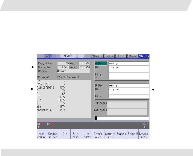
The Input/Output screen is used to carry out NC data input/output between the NC internal memory and the external input/output devices.
Here, the hard disk built into the NC device is also treated as external devices.
In 70 series, only "Memory", "Memory card", "Serial", "Ethernet" and "Anshin-net server" can be used.
(1) 
(2)
 (4)
(4)
(3) |
|
|
|
(5) |
|
|
|
||
|
 (6)
(6)
 (7)
(7)
Display items
|
Display item |
Details |
(1) |
Number of programs |
This displays the registration information of machining program of the selected |
|
registered and remainder |
device. |
|
(Note 1) |
Number of programs registered : |
|
|
This displays the number of programs previously registered as user machining |
|
|
programs. |
|
|
Remainder : |
|
|
This displays the remaining number of programs that can be registered. |
|
|
When "Memory" is selected as the device, the total of the number of programs |
|
|
registered and the remainder is the maximum number of registrations set in the |
|
|
specifications. |
(2) |
Number of memory |
This displays the number of characters of the machining program of the selected |
|
characters and remainder |
device. |
|
(Note 1) |
Number of memory characters : |
|
|
This displays the number of characters previously registered as user machining |
|
|
programs. |
|
|
Remainder : |
|
|
This displays the remaining number of characters that can be registered. The total |
|
|
of the number of memory characters and the remainder is the maximum number of |
|
|
memory characters set in the specifications. |
9

2. Maintenance Screens
|
|
2.1 Input/Output Screen |
|
|
|
|
Display items |
Details |
(3) |
List (Note 2) |
This displays a contents list (directory and file name) of the directory in the setting |
|
|
column (file setting column A or B) where the cursor is currently located. |
|
|
Program : |
|
|
When "Memory" is selected for the device, this displays the file name (program No.) |
|
|
of the machining programs already registered. The file names are displayed in |
|
|
order from the smallest number, from 1 to 99999999. When a device other than |
|
|
memory is selected, this displays the file name and directory to be included in the |
|
|
directory that is set in the current setting column. |
|
|
When the number of characters exceeds 12, the excess is indicated as "*". |
|
|
Character : |
|
|
The size of each file (when memory is selected for the device, the number of |
|
|
characters in the machining program). When directory is selected, this displays |
|
|
"DIR". |
|
|
Comment : |
|
|
This displays the comment (up to 17 alphanumeric characters and symbols) of |
|
|
each file. |
|
|
The date which the file is updated is displayed for the HD, FD, memory card, DS or |
|
|
Ethernet. |
|
|
When the number of characters exceeds 17, the excess is not displayed. |
(4) |
File setting column A |
This sets the device, directory, and file name of the target file for transfer, compare, |
|
|
erasing, etc., operations. |
(5) |
File setting column B |
When transferring, the file name of the transfer origin file is set. When renaming, the |
|
|
file name before renaming is set. When erasing, the erasing range is set. When the |
|
|
number of characters exceeds 28, the excess is not displayed. |
(6) |
Input data |
This displays the data being transferred. |
(7) |
Comparison data |
This displays the data being compared. If an error occurs during comparison, the |
|
|
block with the error is displayed. |
(Note 1) Depending on the device, some items are not displayed.
Device |
Memory |
HD |
Serial |
Memory |
DS |
Ethernet |
FD |
Anshin-net |
|
Display item |
|
|
|
card |
|
|
|
server |
|
Number of programs |
{ |
{ |
× |
{ |
{ |
{ |
{ |
× |
|
registered |
|||||||||
|
|
|
|
|
|
|
|
||
Remainder |
{ |
× |
× |
× |
× |
× |
× |
× |
|
Number of memory |
{ |
{ |
× |
{ |
{ |
{ * |
{ |
× |
|
characters |
|||||||||
|
|
|
|
|
|
|
|
||
Remainder |
{ |
{ |
× |
{ |
{ |
× |
{ |
× |
|
|
|
|
|
|
|
|
|
|
|
List |
{ |
{ |
× |
{ |
{ |
{ |
{ |
× |
|
|
|
|
|
|
|
|
|
|
|
|
|
|
|
|
{ : Displayed |
× : Not displayed |
|||
*: When the Ethernet parameter "#97*1 Host n no total siz" is set to 1, the number of host memory characters will not appear.
(Note 2) The list does not appear when using serial.
10
2. Maintenance Screens
2.1 Input/Output Screen
Menus
|
Menu |
|
Details |
Type |
Reference |
|
|
|
This changes the setting area to file setting column A (transfer origin) |
C |
2.1.1 Changing the Valid |
|
Area |
||||
|
|
or file setting column B (transfer destination). The display of the valid |
|
Area |
|
|
change |
|
|
||
|
|
area (A or B) is highlighted. |
|
|
|
|
|
|
|
|
|
|
|
|
This displays the submenu of the machining program storage area. |
A |
2.1.2 Selecting a |
|
Device |
|
When the submenu is selected, the device is confirmed, and if a |
|
Device, Directory, and |
|
select |
|
directory exists it is set in the root. |
|
File |
|
|
|
The memory is selected as the default. |
|
|
|
|
|
This menu sets the directory that carries out input/ output operations, |
A |
|
|
Dir |
|
|||
|
|
and is on standby for input. Note that when memory is selected for the |
|
|
|
|
|
|
device, the directory can be selected from the submenu. |
|
|
|
|
|
|
||
|
|
|
This menu sets the file name that carries out input/ output operations, |
A |
|
|
File |
|
|
||
|
|
and is on standby for input. When memory is selected for the device, |
|
|
|
|
name |
|
|
|
|
|
|
setting is not necessary if the directory is not the program. |
|
|
|
|
|
|
|
|
|
|
|
|
This updates the list. The list of the directly selected in the currently |
C |
- |
|
List |
|
|||
|
update |
|
valid file setting column (A/B) is updated. |
|
|
|
|
|
|
|
|
|
|
|
This copies the file in file setting column A (transfer origin) to the file |
B |
2.1.3 Transferring a File |
|
Transfr |
|
setting column B (transfer destination). (The transfer origin file is not |
|
|
|
A→B |
|
changed.) A message appears during transfer and when the transfer |
|
|
|
|
|
is completed. |
|
|
|
|
|
This compares the files in file setting column A (transfer origin) and file |
C |
2.1.4 Comparing Files |
|
Compare |
|
|||
|
A:B |
|
setting column B (transfer destination). |
|
(Compare) |
|
|
|
|
|
|
|
|
|
This erases the file in file setting column A. |
B |
|
|
Erase A |
|
|
||
|
|
(Note) The NC memory (excluding programs), serial and Ethernet |
|
|
|
|
|
|
(host file) cannot be erased. |
|
|
|
|
|
|
|
|
|
|
|
This erases the file in file setting column B. |
B |
|
|
Erase B |
|
|
||
|
|
(Note) The NC memory (excluding programs), serial and Ethernet |
|
|
|
|
|
|
(host file) cannot be erased. |
|
|
|
|
|
|
|
|
|
|
|
This changes the name of the file in file setting column A (transfer |
B |
|
|
|
|
origin) to the name of the file in file setting column B (transfer |
|
|
|
Rename |
|
|
|
|
|
|
destination). |
|
|
|
|
A→B |
|
|
|
|
|
|
(Note) The same device must be selected for A and B. |
|
|
|
|
|
|
|
|
|
|
|
|
The NC memory (excluding programs) and serial cannot be renamed. |
|
|
|
|
|
This changes whether to show or hide the comment field. |
B |
|
|
Comment |
|
|
||
|
nondisp |
|
|
|
|
|
|
|
|
|
|
|
|
|
This creates a new directory in the directory of the currently valid file |
A |
|
|
Dir |
|
setting column (A/B). |
|
|
|
create |
|
The directory can be created when HD, FD, memory card or DS is |
|
|
|
|
|
selected for the device. |
|
|
|
|
|
The file contents in the file setting column B are added to the file in the |
B |
|
|
|
|
file setting column A. (The file in the file setting column B is not |
|
|
|
Merge |
|
|
|
|
|
|
changed.) |
|
|
|
|
B→A |
|
|
|
|
|
|
(Note) The NC memory (excluding programs), serial and Ethernet |
|
|
|
|
|
|
|
|
|
|
|
|
(host file) cannot be merged. |
|
|
|
|
|
This formats the FD. |
A |
2.1.5 Formatting an |
|
FD |
|
|||
|
format |
|
This menu is only for 700 series. |
|
External Device |
|
|
|
|
|
|
|
|
|
The formats the front IC card. |
A |
|
|
MemCrd |
|
|
||
|
format |
|
|
|
|
|
|
|
|
|
|
|
|
|
This formats the NC compact flash memory. |
A |
|
|
DS |
|
|
||
|
format |
|
This menu is only for 700 series. |
|
|
|
|
|
|
|
|
|
|
|
This cancels a warning from network service. |
C |
|
|
Warning |
|
|
||
|
cancel |
|
|
|
|
|
|
|
|
|
|
|
|
|
This interrupts the process (transfer, compare, etc.) during execution. |
C |
- |
|
Stop |
|
|||
|
|
|
|
|
|
|
|
|
|
|
|
|
|
|
|
|
|
11

2. Maintenance Screens
2.1 Input/Output Screen
2.1.1 Changing the Valid Area
When setting the file setting field A or B device, directory and file name on this screen, the area containing these must be valid.
The display area can be changed by pressing the menu key ( Area change ) or the cursor key  and
and  . After changing, the data setting operation is valid in that area.
File setting field A is valid. |
File setting field B is valid. |
Changing the valid file setting field
When file setting field A (top) is valid
(1) Press the menu Area change .
This can also be changed with the cursor key  .
.
The file setting field B (bottom) is validated.
12

2. Maintenance Screens
2.1 Input/Output Screen
2.1.2 Selecting a Device, Directory and File
File selection sequence
Designate the device where the target file is located. → Select from the sub menu.
↓
Designate the directory with a full path.
↓
→ Input the full path or select from the list.
|
|
|
Designate the file name. |
|
|
|
|
|
|
→ Input the file name or select from the list. |
|
|
|||||||
|
|
|
|
|
|
|
|
|
|
|
|
|
|
|
|
|
|
|
|
Menu used |
|
|
|
|
|
|
|
|
|
|
|
|
|
|
|
||||
|
|
|
|
|
|
menu's submenus |
|
|
|
|
|
|
|
|
|||||
|
Device select |
|
|
|
|
|
|
|
|
||||||||||
|
|
|
|
|
|
|
|
|
|
|
|
|
|
|
|
|
|
|
|
|
|
|
Menu |
|
|
|
|
|
|
|
Details |
Type |
Reference |
|
|
||||
|
|
|
|
|
|
This selects the NC memory (program, parameter, user PLC, NC |
C |
- |
|
|
|||||||||
|
|
Memory |
|
|
|||||||||||||||
|
|
|
data). |
|
|
|
|
|
|
|
|
|
|
|
|||||
|
|
|
|
|
|
|
|
|
|
|
|
|
|
|
|
|
|||
|
|
|
|
|
|
|
|
|
|
|
|
|
|
|
|
|
|
||
|
|
|
|
|
|
This selects the hard disk. |
|
|
|
|
C |
- |
|
|
|||||
|
|
|
|
HD |
|
|
|
|
|
|
|||||||||
|
|
|
|
|
This menu is only for 700 series. |
|
|
|
|
||||||||||
|
|
|
|
|
|
|
|
|
|
||||||||||
|
|
|
|
|
|
|
|
|
|
|
|
|
|
|
|
|
|||
|
|
|
|
|
|
This selects the RS-232C device (PC, tape, etc.). |
C |
- |
|
|
|||||||||
|
|
|
Serial |
|
|
||||||||||||||
|
|
|
|
|
|
|
|
|
|
|
|
|
|
|
|
|
|
||
|
|
|
|
|
|
|
|
|
|
|
|
|
|
|
|
||||
|
|
|
|
|
|
|
|
|
|
|
|
|
|
|
|
||||
|
|
|
|
|
|
This selects the front IC card. |
C |
- |
|
|
|||||||||
|
|
Memory |
|
|
|||||||||||||||
|
|
|
card |
|
|
|
|
|
|
|
|
|
|
|
|
|
|
|
|
|
|
|
|
|
|
|
|
|
|
|
|
|
|
|
|
|
|||
|
|
|
|
|
|
This selects the NC compact flash memory. |
C |
- |
|
|
|||||||||
|
|
|
|
DS |
|
|
|||||||||||||
|
|
|
|
|
This menu is only for 700 series. |
|
|
|
|
||||||||||
|
|
|
|
|
|
|
|
|
|
||||||||||
|
|
|
|
|
|
|
|
|
|
|
|
|
|
|
|
|
|||
|
|
|
|
|
|
This selects the Ethernet-connected host computer. |
C |
- |
|
|
|||||||||
|
|
Ethernet |
|
|
|||||||||||||||
|
|
|
|
|
|
|
|
|
|
|
|
|
|
|
|
|
|||
|
|
|
|
|
|
|
|
|
|
|
|
|
|
|
|
|
|||
|
|
|
|
|
|
|
|
|
|
|
|
|
|
|
|
|
|||
|
|
|
|
|
|
This selects the floppy disk. |
C |
- |
|
|
|||||||||
|
|
|
|
FD |
|
|
|||||||||||||
|
|
|
|
|
This menu is only for 700 series. |
|
|
|
|
||||||||||
|
|
|
|
|
|
|
|
|
|
||||||||||
|
|
|
|
|
|
|
|
|
|
|
|
|
|
|
|
|
|||
|
|
|
|
|
|
This selects the Anshin-net server. |
C |
|
|
|
|||||||||
|
|
|
Anet |
|
|
|
|||||||||||||
|
|
|
server |
|
|
|
|
|
|
|
|
|
|
|
|
|
|
|
|
|
|
|
|
|
|
|
|
|
|
|
|
|
|
|
|
|
|
|
|
|
|
|
|
|
|
|
|
|
|
menu submenus |
|
|
|
|
|||||
|
Dir |
(other than memory) and |
|
File name |
|
|
|
|
|||||||||||
|
|
|
|
|
|
|
|
|
|
|
|
|
|
|
|
|
|||
|
|
|
Menu |
|
|
|
|
|
|
|
Details |
Type |
Reference |
|
|
||||
|
|
|
|
|
|
The cursor appears in the list display. The list contents can be |
A |
- |
|
|
|||||||||
|
|
|
|
|
|
selected with the |
|
INPUT |
key. |
|
|
|
|
||||||
|
|
|
From |
|
When a directory |
is selected, |
the contents of the selected directory |
|
|
|
|
||||||||
|
|
|
|
list |
|
are displayed in the list. Continued selection is possible. |
|
|
|
|
|||||||||
|
|
|
|
|
|
When a file name is selected, the file name is temporarily displayed in |
|
|
|
|
|||||||||
|
|
|
|
|
|
the input area. When the |
|
INPUT |
key is pressed again, it is fixed. |
|
|
|
|
||||||
|
|
|
|
|
|
|
|
|
|
|
|
|
|
|
|
|
|
|
|
13

2. Maintenance Screens
|
|
|
|
|
|
|
2.1 Input/Output Screen |
|||||
|
|
|
|
|
|
|
|
|
|
|
|
|
Selecting methods for device, directory, and file name |
|
|
|
|
|
|
|
|
||||
|
|
|
|
|
|
|
|
|
|
|
|
|
|
Device |
Designation target file |
|
Designation method |
|
|
|
|||||
|
Device |
Directory |
File name |
|
|
|
||||||
|
|
|
|
|
|
|
||||||
|
NC memory |
• |
Machining program |
Select from the |
- |
|
|
Key input in the input |
|
|||
|
|
• |
User macro |
submenu |
(Default) |
|
|
area, and press |
|
INPUT |
|
|
|
|
• |
Fixed cycle |
|
|
|
|
|
|
|
|
|
|
|
|
|
|
|
Select from the list |
|
|||||
|
|
|
|
|
|
|
|
|
||||
|
|
Other than the |
Select from the |
Key input in the input area, |
- |
|
|
|
|
|||
|
|
machining program |
submenu |
and press |
INPUT |
|
(Fixed) |
|
|
|
||
|
|
|
|
|
|
|
|
|
|
|
||
|
|
|
|
|
Select from the submenu |
|
|
|
|
|
||
|
|
|
|
|
|
|
||||||
|
Other than the |
All |
Select from the |
Key input in the input area, |
Key input in the input |
|
||||||
|
NC memory |
|
|
submenu |
and press |
INPUT |
|
area, and press |
|
INPUT |
|
|
|
|
|
|
|
|
|
|
|||||
|
|
|
|
|
Select from the list |
Select from the list |
|
|||||
The device can be selected from the submenu. (The devices that can be used will differ depending on the specifications.)
One of the following methods can be used to designate the directory (for devices other than the NC memory) and file name.
• |
Set the directory path (full path) or file name in the input area, and press the |
INPUT |
key. |
|||||||
• |
Press submenu |
From list |
of the menu |
Dir |
or |
File name |
. Move the |
cursor to the target directory or |
||
|
|
|
|
|
|
|
|
|
|
|
file name, and press the INPUT key.
A wild card (*) can be used when selecting a file name.
Notes when selecting a file
(1)During directory and file name setting, the designated directory, path or file name will be set, even if it does not actually exist. This will not cause an error. Note that the previously set directory is overwritten.
(2)When a file in the NC memory other than a machining program is designated, it is not necessary to set the file name. (The file name is fixed.)
(3)When a file name is selected from the menu, it first is displayed in the input area. However, at this time the
file name has not yet been fixed. Press the INPUT key again to fix the file name.
(4)When the  key is pressed when setting a file name, the file name in the input area is erased.
(5)When a fixed cycle program is designated, the basic common parameters "#1166 fixpro" must be set. Select "Memory" for the device, and "Program" for the directory.
14

2. Maintenance Screens
2.1 Input/Output Screen
Selecting an NC memory program
(1) |
Press the menu |
|
. |
|
The following menu appears. |
Device select |
|
||||
|
|
|
|
|
|
|
|
|
|
|
|
(When specifications of all devices is valid.)
(2) Press the menu Memory .
(3) Press the menu File name .
<When inputting the file name from the input area>
(4) Input the file name
10013 INPUT
<When selecting the file name from the list>
(4)-1 Press the menu From list .
(4)-2 Move the cursor to file name to be selected, and fix.
 ,
,  , INPUT
(4)-3 Press the INPUT key.
"Memory" appears in the device name, and the default "Program" appears in the directory.
The following menu appears.
The cursor appears in the list.
The selected file name appears in the input area.
The selected file name appears.
15

2. Maintenance Screens
2.1 Input/Output Screen
Designating multiple files
(1)Designating multiple serial files
Multiple serial files can be transferred, compared and erased in the file setting column A. Set as follows in this case.
File : First file name
-: Last file name
(2)Using a wild card
A wild card (*) can be used in the file name.
(Note) When serial or Anshin-net server is used, multiple files cannot be compared.
File : * |
All files will be selected. |
-
Selecting an NC memory file other than a program
(1) |
Press the menu |
|
. |
|
The following menu appears. |
Device select |
|
||||
|
|
|
|
|
|
|
|
|
|
|
|
(When specifications of all devices is valid.)
(2) Press the menu Memory .
"Memory" appears in the device name, and "Program" appears as the default in the directory.
(3) |
Select the menu |
|
. |
|
The following menu appears. |
Dir |
|
||||
|
|
|
|
|
|
|
|
|
|
|
|
(4) |
Press the menu |
|
. |
|
The directory and file name appear. |
Tool offset |
|
||||
|
|
|
|
|
|
|
|
|
|
|
|
(Note) The file name for each directory is fixed. Refer to "2.1.6 List of file names" for the file names.
16
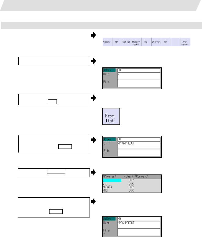
2. Maintenance Screens
2.1 Input/Output Screen
Selecting a device file other than the NC memory
(1) |
Press the menu |
|
. |
|
The following menu appears. |
Device select |
|
||||
|
|
|
|
|
|
|
|
|
|
|
|
(When specifications of all devices is valid.)
(2) Select a device.
(3) Designate the directory. Select the menu Dir
<When inputting the directory from the input area>
(4) Input the directory path as a full path.
/PRG/PRECUT INPUT
<When selecting the directory from the list >
The device name appears. The root directory is selected as the default.
The mode changes to the mode for inputting the directory name.
The following menu appears.
(4)-1 Press the menu From list
(4)-2 Move the cursor to directory to be selected, and fix.
 ,
,  , INPUT
Repeat this operation until the target directory is reached.
When the target directory is reached, press the  key and quit the mode for inputting the directory.
The cursor appears in the list.
The selected directory appears in the data setting column.
The contents of the selected directory appear in the list.
17

2. Maintenance Screens
|
|
|
|
|
|
2.1 Input/Output Screen |
|
|
|
|
|
||
(5) |
Designate the file name. |
|
|
The mode changes to the mode for inputting the file |
||
|
Press the menu |
File name |
|
|
name. |
|
|
|
|
|
|
The following menu appears. |
|
|
|
|
|
|
||
|
|
|
|
|
|
|
<When inputting the file name from the input area>
(6) Input the file name
10013.PRG INPUT
<When selecting the file name from the list>
(6)-1 |
Press the menu |
|
. |
|
The cursor appears in the list. |
From list |
|
||||
|
|
|
|
|
|
|
|
|
|
|
|
(6)-2 |
Move the cursor to file name to be |
|
The selected file name appears in the input area. |
||||||||
|
selected, and fix. |
|
|
|
|
|
|
|
|||
|
|
|
|
|
|
|
|
||||
|
, |
, |
|
|
|
|
|
|
|
|
|
(6)-3 |
|
INPUT |
|
|
The selected file name appears. |
||||||
|
|
|
|
|
|
||||||
|
|
|
|
|
|
||||||
Press the |
|
INPUT |
|
key. |
|
||||||
|
|
|
|
|
|
|
|
|
|
|
|
|
|
|
|
|
|
|
|
|
|
|
|
18
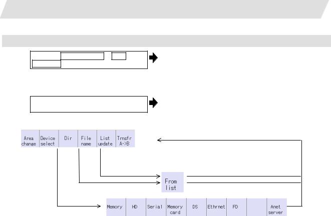
2. Maintenance Screens
Canceling the input mode
(1) Press the Device Select , Dir or
File name .
To cancel the data input at this time, press the  key.
key.
(2) Press the  key.
key.
Main menu
2.1 Input/Output Screen
The submenu appears.
The details in the input area are erased, and the main menu appears.
 The details in the data input area are erased.
Submenu
(When specifications of all devices is valid.)
19

2.Maintenance Screens
2.1.3Transferring a File
Operating method
(1) Press the menu Area change , and select file setting column A.
(2)Designate the transfer origin device, directory and file name.
(3) Press the menu Area change , and select file setting column B.
(4)Designate the transfer destination device, directory and file name.
(5) Press the menu Trnsfr A ->B .
(6) Press Y or INPUT .
2.1 Input/Output Screen
The designated file appears.
Multiple files can be designated in the file setting column A. Designate the first and last file name of the target range. A wildcard "*" can be designated for the file name.
The designated file appears.
A message appears to confirm the transfer.
The file transfer starts. The data being transferred appears in the input data display column.
A message appears when the transfer is completed.
INP data : G91 G28 XYZ;
F1000;
CMP data :
!Caution
!" ; ", "EOB", "%", and “EOR” are symbols used for explanation. The actual codes for ISO are "CR, LF" ("LF")
and "%".
The programs created on the Edit screen are stored in the NC memory in a "CR, LF" format, however, the programs created with external devices such as the FD or RS-232C may be stored in an "LF" format.
The actual codes for EIA are "EOB (End of Block)" and "EOR (End of Record)".
!To prevent the influence of data loss and data transformation over the line, always carry out data comparison after transferring a machining program.
20
Loading...