


11D-1
GROUP 11D
ENGINE OVERHAUL <4G63-Turbo>
CONTENTS
HOW TO USE THIS MANUAL. . . . . . 11D-2
GENERAL INFORMATION . . . . . . . . 11D-4 GENERAL SPECIFICATIONS . . . . . . 11D-4
SERVICE SPECIFICATIONS. . . . . . . 11D-5 REWOK DIMENSIONS . . . . . . . . . . . 11D-6
TORQUE SPECIFICATIONS . . . . . . . 11D-7
SEALANTS . . . . . . . . . . . . . . . . . . . . 11D-10
SPECIAL TOOLS. . . . . . . . . . . . . . . . 11D-11
ALTERNATOR AND IGNITION
SYSTEM . . . . . . . . . . . . . . . . . . . . . . . 11D-14
REMOVAL AND INSTALLATION . . . . . . . . 11D-14
SOLENOID AND VACUUM HOSE . . 11D-15
REMOVAL AND INSTALLATION . . . . . . . . 11D-15
TIMING BELT. . . . . . . . . . . . . . . . . . . 11D-16
REMOVAL AND INSTALLATION . . . . . . . . 11D-16 INSPECTION . . . . . . . . . . . . . . . . . . . . . . . 11D-26
FUEL AND EMISSION PARTS . . . . . 11D-28
REMOVAL AND INSTALLATION . . . . . . . . 11D-28
INLET MANIFOLD . . . . . . . . . . . . . . . 11D-30
REMOVAL AND INSTALLATION . . . . . . . . 11D-30
EXHAUST MANIFOLD . . . . . . . . . . . . 11D-31
REMOVAL AND INSTALLATION . . . . . . . . 11D-31
WATER PUMP AND WATER
HOSE . . . . . . . . . . . . . . . . . . . . . . . . . 11D-33
REMOVAL AND INSTALLATION . . . . . . . . 11D-33
ROCKER ARMS AND CAMSHAFT . . 11D-35
REMOVAL AND INSTALLATION . . . . . . . . 11D-35 INSPECTION. . . . . . . . . . . . . . . . . . . . . . . . 11D-37
CYLINDER HEAD AND VALVES. . . . 11D-40
REMOVAL AND INSTALLATION . . . . . . . . 11D-40 INSPECTION. . . . . . . . . . . . . . . . . . . . . . . . 11D-43
OIL PAN AND OIL PUMP. . . . . . . . . . 11D-46
REMOVAL AND INSTALLATION . . . . . . . . 11D-46 INSPECTION. . . . . . . . . . . . . . . . . . . . . . . . 11D-53
PISTON AND CONNECTING ROD . . 11D-55
REMOVAL AND INSTALLATION . . . . . . . . 11D-55 INSPECTION. . . . . . . . . . . . . . . . . . . . . . . . 11D-60
CRANKSHAFT AND CYLINDER
BLOCK . . . . . . . . . . . . . . . . . . . . . . . . 11D-62
REMOVAL AND INSTALLATION . . . . . . . . 11D-62 INSPECTION. . . . . . . . . . . . . . . . . . . . . . . . 11D-66
11D-2 |
ENGINE OVERHAUL <4G63-Turbo> |
|
|
|
HOW TO USE THIS MANUAL |
|
HOW TO USE THIS MANUAL |
M1113025100296
HOW TO USE THIS MANUAL
Scope of Service Explanations
This manual describes service procedures performed after removal of the engine from the vehicle.
For removal of the engine from the vehicle, installation of the engine in the vehicle, and on-vehicle inspection and service of the engine, please use the separate Workshop Manuals prepared for the vehicle.
How to Read Explanations
Service steps
(1)A component part drawing is shown at the beginning of each section to enable the technician to ascertain the installed condition of the component parts.
(2)Service steps are indicated by means of numbers in the component part drawing. Non-reusable parts are indicated as such,
and tightening torques are shown. ·Removal steps
The numbers of the part names match the numbers in the component part drawing and indicate the removal sequence. ·Installation steps
Installation steps are omitted wherever installation can be achieved simply by performing the removal steps in reverse. ·Disassembly steps
The numbers of the part names match the numbers in the component part drawing and indicate the disassembly sequence. ·Reassembly steps
Reassembly steps are omitted wherever reassembly can be achieved simply by performing the disassembly steps in reverse.
Classification of Service Points
Key service points, service standards, and instructions for using special tools are collated as service points and explained in detail.
<<A>>: Outward-pointing brackets denote removal service points or disassembly service points.
>>A<<: Inward-pointing brackets denote installation service points or reassembly service points.
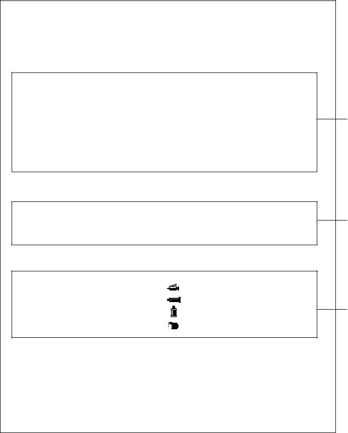
Lubricant and Sealant Symbols
Every location where a lubricant or sealant must be applied or added is indicated using a relevant symbol in the component part drawing and/or on the page after the component part drawing.
. . . . . . . . . . Grease
. . . . . . . . . . Sealant or form-in-place gasket (FIPG) |
. . . . . . . . . . Brake fluid
. . . . . . . . . . Engine oil or gear oil
Inspection
Only those inspection procedures which use special tools or measuring appliances are described. You must perform general visual inspection and part cleaning whenever necessary although their procedures are not described in this manual.
AK202851
ENGINE OVERHAUL <4G63-Turbo> |
11D-3 |
HOW TO USE THIS MANUAL |
|
Page number |
|
Group title |
|
Section title |
||
|
|
|
|
|
|
|
|
|
|
|
|
|
|
|
|
|
|
|
|
|
11-54 |
ENGINE OVERHAUL |
|
|
|
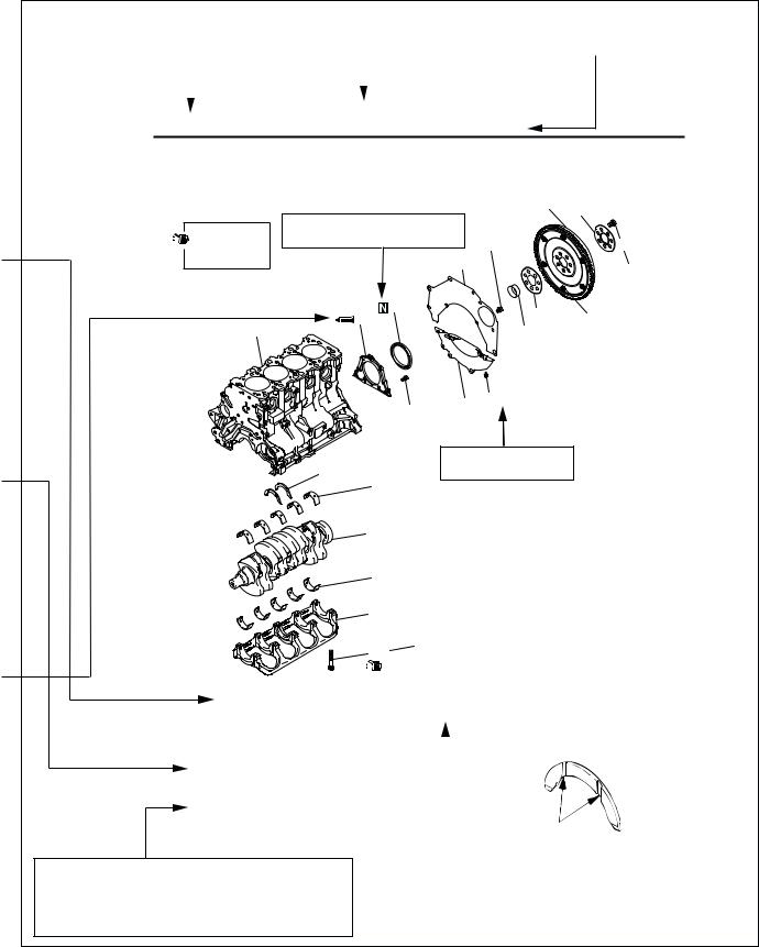
CRANKSHAFT AND CYLINDER BLOCK |
|
|
||
CRANKSHAFT AND CYLINDER BLOCK |
|
|||
REMOVAL AND INSTALLATION |
|
|
|
|
|
|
3 |
2 |
|
|
|
|
|
|
Apply engine oil |
Denotes non-reusable part. |
|
|
|
to all moving |
|
11 ± 1 N·m |
|
1 |
parts before |
|
|
||
|
|
|
|
|
installation. |
|
6 |
|
132 ± 5 N·m |
|
|
|
|
|
|
9 |
4 |
|
A |
16 |
8 |
|
||
|
5 |
|
|
|
|
|
9.0 ± 1.0 N·m |
|
|
|
11 ± 1 N·m |
7 |
|
|
Tightening torque
15
14
13
12
11
25 ± 2 N·m + 90º to 100º
10
Removal steps 1. Drive plate bolt 2. Adapter plate 3. Drive plate
4. Crankshaft bushing
5. Rear plate
6. Bellhousing cover >>E<< 7. Oil seal case >>D<< 8. Oil seal
>>C<< 9. Bearing cap bolt 10. Bearing cap
>>B<< 11. Crankshaft bearing, lower >>A<< 12. Crankshaft
The alphabetical character in this category of heading matches that of the relevant removal steps, installation steps, disassembly steps, or reassembly steps.
AK204351AB
INSTALLATION SERVICE POINTS
>>A<< THRUST BEARING INSTALLATION
|
|
Grooves |
|
|
|
|
AK100786AB |
|
|
|
|
|
|
|
Procedures and cautions for removal, instal- |
|
|
||
lation, disassembly, and reassembly are ex- |
|
|
||
plained under this category of heading. |
|
AK300250 |
||
|
|
|
|
|
11D-4 |
ENGINE OVERHAUL <4G63-Turbo> |
|
|
|
GENERAL INFORMATION |
GENERAL INFORMATION
VEHICLE AND ENGINE MODELS |
|
M1113000100523 |
|||
|
|
|
|||
|
|
|
|
|
|
Vehicle name |
Vehicle |
Engine model |
Displacement |
Specification |
|
|
model |
|
mL |
|
|
OUTLANDER |
CU2W |
4G63-7 |
1,997 |
Double overhead camshaft, 16-valve |
|
|
|
|
|
|
|
|
GENERAL SPECIFICATIONS |
||
|
|
M1113000200779 |
|
|
|
|
|
Item |
|
Specification |
|
|
|
|
|
Bore × stroke mm |
|
85 × 88 |
|
|
|
|
|
Displacement mL |
|
1,997 |
|
|
|
|
|
Combustion chamber |
|
Pentroof type |
|
|
|
|
|
Number of cylinders |
|
4 |
|
|
|
|
|
Valve mechanism |
Type |
Double overhead camshaft |
|
|
|
|
|
|
Number of intake valves |
2 |
|
|
|
|
|
|
Number of exhaust |
2 |
|
|
valves |
|
|
|
|
|
|
|
Lash adjusters |
Hydraulic |
|
|
|
|
|
|
Rocker arms |
Roller cam followers |
|
|
|
|
|
Compresssion ratio |
|
9.0 |
|
|
|
|
|
Fuel injection system |
|
Electronically controlled multi-point injection (MPI) |
|
|
|
system |
|
|
|
|
|
Ignition system |
|
Electronically controlled two-coil system |
|
|
|
|
|
Generator |
|
Alternator (with built-in IC regulator) |
|
|
|
|
|
Starter motor |
|
Gear reduction drive type |
|
|
|
|
|
ENGINE OVERHAUL <4G63-Turbo> |
11D-5 |
SERVICE SPECIFICATIONS |
|
SERVICE SPECIFICATIONS
M1113000300776
Item |
|
Standard value |
Limit |
|
TIMING BELT |
|
|
|
|
|
|
|
|
|
Auto-tensioner rod extension length |
|
3.8 − 4.5 |
− |
|
(with timing belt installed) mm |
|
|
|
|
|
|
|
||
Auto-tensioner rod extension length (when free) mm |
12.0 |
− |
||
|
|
|
|
|
Auto-tensioner rod retraction length |
|
Less than 1 |
− |
|
(when pressed with force of 98 to 196 N) mm |
|
|
||
|
|
|
|
|
ROCKER ARMS AND CAMSHAFTS |
|
|
|
|
|
|
|
|
|
Cam height mm |
|
34.91 |
34.41 |
|
|
|
|
|
|
CYLINDER HEAD AND VALVES |
|
|
|
|
|
|
|
||
Cylinder head gasket surface warp mm |
Less than 0.05 |
0.2 |
||
|
|
|
||
Cylinder head gasket surface grinding limit |
− |
0.2 |
||
(including cylinder block grinding amount) mm |
|
|
||
|
|
|
|
|
Cylinder head overall height mm |
|
131.9 − 132.1 |
− |
|
|
|
|
||
Cylinder head bolt nominal length mm |
− |
99.4 |
||
|
|
|
|
|
Valve margin mm |
|
Intake valves |
1.0 |
0.5 |
|
|
|
|
|
|
|
Exhaust valves |
1.5 |
1.0 |
|
|
|
|
|
Valve stem diameter mm |
|
|
6.6 |
− |
|
|
|
|
|
Valve face angle |
|
43.5° − 44° |
− |
|
|
|
|
|
|
Valve stem-to-guide clearance mm |
|
Intake valves |
0.02 − 0.05 |
0.10 |
|
|
|
|
|
|
|
Exhaust valves |
0.05 − 0.09 |
0.15 |
|
|
|
|
|
Valve height mm |
|
Intake valves |
109.5 |
109.0 |
|
|
|
|
|
|
|
Exhaust valves |
109.7 |
109.2 |
|
|
|
|
|
Valve stem projection mm |
|
Intake valves |
49.2 |
49.7 |
|
|
|
|
|
|
|
Exhaust valves |
48.4 |
48.9 |
|
|
|
|
|
Valve spring free height mm |
|
|
47.0 |
46.0 |
|
|
|
|
|
Valve spring load/height N/mm |
|
240/40 |
− |
|
|
|
|
|
|
Valve spring squareness |
|
1.5° or smaller |
4° |
|
|
|
|
|
|
Valve face-to-seat contact width mm |
|
0.9 − 1.3 |
− |
|
|
|
|
|
|
Valve guide inside diameter mm |
|
6.6 |
− |
|
|
|
|
|
|
Valve guide press-in height mm |
|
19.2 − 19.8 |
− |
|
|
|
|
|
|
OIL PAN AND OIL PUMP |
|
|
|
|
|
|
|
|
|
Oil pump gear side clearance mm |
|
Drive gear |
0.08 − 0.14 |
− |
|
|
|
|
|
|
|
Driven gear |
0.06 − 0.12 |
− |
|
|
|
|
|
Oil cooler by-pass valve mm |
|
Dimension (Normal |
34.5 |
− |
|
|
temperature) |
|
|
|
|
|
|
|
|
|
By-pass hole closing |
40.0 |
− |
|
|
temperature 97 to |
|
|
|
|
103°C |
|
|
|
|
|
|
|
11D-6 |
ENGINE OVERHAUL <4G63-Turbo> |
|
|
|
|
|
|
||
|
REWOK DIMENSIONS |
|
|
|
|
|
|
|
|
Item |
|
Standard value |
Limit |
|
|
|
|
|
|
Oil pressure at curb idle speed kPa |
|
78 or more |
− |
|
[oil temperature is 75 to 90°] |
|
|
|
|
|
|
|
|
|
PISTONS AND CONNECTING RODS |
|
|
|
|
|
|
|
|
|
Piston outside diameter mm |
|
85.0 |
− |
|
|
|
|
|
|
Piston ring side clearance in ring |
No. 1 |
0.03 − 0.07 |
0.1 |
|
groove mm |
|
|
|
|
No. 2 |
0.02 − 0.06 |
0.1 |
|
|
|
|
|||
|
|
|
|
|
Piston ring end gap mm |
No. 1 |
0.20 − 0.30 |
0.8 |
|
|
|
|
|
|
|
No. 2 |
0.30 − 0.45 |
0.8 |
|
|
|
|
|
|
|
Oil ring |
0.10 − 0.40 |
1.0 |
|
|
|
|
|
|
Piston pin outside diameter mm |
|
22.0 |
− |
|
|
|
|
|
|
Piston pin press-in load (at ambient temperature) N |
7,350 − 17,100 |
− |
|
|
|
|
|
|
|
Oil clearance at crankshaft pins mm |
|
0.03 − 0.05 |
0.1 |
|
|
|
|
|
|
Connecting rod big end thrust clearance mm |
0.10 − 0.25 |
0.4 |
|
|
|
|
|
|
|
CRANKSHAFT AND CYLINDER BLOCK |
|
|
|
|
|
|
|
|
|
Crankshaft end play mm |
|
0.05 − 0.25 |
0.4 |
|
|
|
|
|
|
Crankshaft journal diameter mm |
|
57.0 |
− |
|
|
|
|
|
|
Crankshaft pin diameter mm |
|
45.0 |
− |
|
|
|
|
|
|
Oil clearance at crankshaft journals mm |
0.03 − 0.04 |
0.1 |
|
|
|
|
|
|
|
Cylinder block gasket surface warp mm |
0.05 |
0.1 |
|
|
|
|
|
|
|
Cylinder block gasket surface grinding limit |
− |
0.2 |
|
|
(including cylinder head grinding amount) mm |
|
|
|
|
|
|
|
|
|
Cylinder block overall height mm |
|
284 |
− |
|
|
|
|
|
|
Cylinder bore diameter mm |
|
85 |
− |
|
|
|
|
|
|
Taper of cylinder mm |
|
0.01 or less |
− |
|
|
|
|
|
|
Cylinder-to-piston clearance mm |
|
0.02 − 0.04 |
− |
|
|
|
|
|
|
Crankshaft bearing cap bolt nominal length mm |
− |
71.1 |
|
|
|
|
|
|
|
REWOK DIMENSIONS
|
|
|
M1113024300394 |
|
|
|
|
|
|
Item |
|
|
Standard value |
|
|
|
|
|
|
CYLINDER HEAD AND VALVES |
|
|
|
|
|
|
|
|
|
Diameter of oversize valve seat ring hole in cylinder head |
Intake |
0.3 oversize |
35.30 − 35.33 |
|
mm |
|
|
|
|
|
0.6 oversize |
35.60 − 35.63 |
|
|
|
|
|
||
|
|
|
|
|
|
Exhaust |
0.3 oversize |
33.30 − 33.33 |
|
|
|
|
|
|
|
|
0.6 oversize |
33.60 − 33.63 |
|
|
|
|
|
|
Diameter of oversize valve guide hole in cylinder head mm |
|
0.05 oversize |
12.05 − 12.07 |
|
|
|
|
|
|
|
|
0.25 oversize |
12.25 − 12.27 |
|
|
|
|
|
|
|
|
0.50 oversize |
12.50 − 12.52 |
|
|
|
|
|
|
ENGINE OVERHAUL <4G63-Turbo> |
11D-7 |
||||
TORQUE SPECIFICATIONS |
|
|
|
|
|
TORQUE SPECIFICATIONS |
|
|
|||
|
|
|
|
M1113023400989 |
|
|
|
|
|
|
|
Item |
|
N m |
|
|
|
ALTERNATOR AND IGNITION COIL |
|
|
|
|
|
|
|
|
|
|
|
Oil level gauge guide bolt |
|
13 |
± 1 |
|
|
|
|
|
|
|
|
Idler pulley bolt |
|
79 |
± 5 |
|
|
|
|
|
|
|
|
Auto-tensioner assembly bolt (M8) |
|
24 |
± 4 |
|
|
|
|
|
|
|
|
Auto-tensioner assembly bolt (M10) |
|
44 |
± 10 |
|
|
|
|
|
|
|
|
Water pump pulley bolts |
|
8.8 ± 1.0 |
|
|
|
|
|
|
|
|
|
Alternator brace bolt (flange bolt) |
|
23 |
± 3 |
|
|
|
|
|
|
|
|
Alternator brace bolts (washer assembled bolt) |
|
22 |
± 4 |
|
|
|
|
|
|
|
|
Alternator nuts |
|
44 |
± 10 |
|
|
|
|
|
|
|
|
Crankshaft pulley bolts |
|
25 |
± 4 |
|
|
|
|
|
|
|
|
Center cover bolts |
|
3.0 ± 0.5 |
|
|
|
|
|
|
|
|
|
Ignition coil bolts |
|
10 |
± 2 |
|
|
|
|
|
|
|
|
Spark plugs |
|
25 |
± 5 |
|
|
|
|
|
|
|
|
SOLENOID AND VACUUM HOSE |
|
|
|
|
|
|
|
|
|
|
|
Vacuum pipe and hose assembly bolts |
|
11 ± 1 |
|
|
|
|
|
|
|
|
|
EGR valve bolts |
|
20 |
± 2 |
|
|
|
|
|
|
|
|
Engine hanger bolt |
|
19 |
± 3 |
|
|
|
|
|
|
|
|
Solenoid valve assembly nut |
|
36 |
± 6 |
|
|
|
|
|
|
|
|
Solenoid valve assembly bolts(M6) |
|
9.0 ± 1.0 |
|
|
|
|
|
|
|
|
|
Solenoid valve assembly bolts(M8) |
|
23 |
± 4 |
|
|
|
|
|
|
|
|
TIMING BELT |
|
|
|
|
|
|
|
|
|
|
|
Timing belt cover bolts (flange bolt) |
|
11 ± 1 |
|
|
|
|
|
|
|
|
|
Timing belt cover bolt (washer-assembled bolt) |
|
9.0 ± 1.0 |
|
|
|
|
|
|
|
|
|
Power steering pump bracket bolts |
|
49 |
± 9 |
|
|
|
|
|
|
|
|
Tensioner pulley bolt |
|
48 |
± 5 |
|
|
|
|
|
|
|
|
Tensioner arm bolt |
|
21 |
± 4 |
|
|
|
|
|
|
|
|
Auto-tensioner bolts |
|
23 |
± 3 |
|
|
|
|
|
|
|
|
Idler pulley bolt |
|
35 |
± 6 |
|
|
|
|
|
|
|
|
Crankshaft angle sensor bolts |
|
8.8 ± 1.0 |
|
|
|
|
|
|
|
|
|
Oil pump sprocket nut |
|
54 |
± 4 |
|
|
|
|
|
|
|
|
Crankshaft bolt |
|
167 |
|
|
|
|
|
|
|
|
|
Tensioner "B" bolt |
|
19 |
± 3 |
|
|
|
|
|
|
|
|
Counterbalance shaft sprocket bolt |
|
45 |
± 3 |
|
|
|
|
|
|
|
|
Rocker cover bolts |
|
3.5 ± 0.5 |
|
|
|
|
|
|
|
|
|
Engine support bracket bolts |
|
49 |
± 5 |
|
|
|
|
|
|
|
|
Camshaft sprocket bolts |
|
88 |
± 10 |
|
|
|
|
|
|
|
|
11D-8 |
ENGINE OVERHAUL <4G63-Turbo> |
|||||
|
||||||
|
|
TORQUE SPECIFICATIONS |
|
|
||
|
|
|
|
|
|
|
Item |
|
|
N m |
|
|
|
|
|
|
|
|
|
|
FUEL SYSTEM |
|
|
|
|
|
|
|
|
|
|
|
|
|
Throttle body bolts |
|
|
19 |
± |
3 |
|
|
|
|
|
|
||
Fuel pressure regulator bolts |
|
|
9.0 ± 2.0 |
|
||
|
|
|
|
|||
Delivery pipe and injector assembly bolts |
|
11 ± 1 |
|
|||
|
|
|
|
|
|
|
INLET MANIFOLD |
|
|
|
|
|
|
|
|
|
|
|
|
|
Inlet manifold stay bolts |
|
|
31 |
± |
3 |
|
|
|
|
|
|
|
|
Inlet manifold bolts (M8) |
|
|
20 |
± |
2 |
|
|
|
|
|
|
|
|
Inlet manifold bolts and nuts (M10) |
|
|
36 |
± |
6 |
|
|
|
|
|
|
|
|
Detonation sensor |
|
|
23 |
± |
2 |
|
|
|
|
|
|
|
|
EXHAUST MANIFOLD |
|
|
|
|
|
|
|
|
|
|
|
|
|
Engine hanger bolt |
|
|
19 |
± |
3 |
|
|
|
|
|
|
|
|
Turbocharger heat protector bolts |
|
|
23 |
± |
3 |
|
|
|
|
|
|
|
|
Oxygen sensor |
|
|
44 |
± |
5 |
|
|
|
|
|
|
|
|
Exhaust fitting bracket bolts |
|
|
36 |
± |
5 |
|
|
|
|
|
|
|
|
Exhaust fitting bolts |
|
|
59 |
± |
5 |
|
|
|
|
|
|
|
|
Air outlet fitting bolts |
|
|
19 |
± |
1 |
|
|
|
|
|
|
|
|
Oil return pipe bolts |
|
|
14 |
± |
1 |
|
|
|
|
|
|
|
|
Exhaust manifold heat protector bolts |
|
|
23 |
± |
3 |
|
|
|
|
|
|
||
Turbocharger assembly and pipe assembly bolts, nuts |
59 |
± |
5 |
|
||
|
|
|
|
|
||
Oil pipe bolt (flange bolt) |
|
|
11 ± 1 |
|
||
|
|
|
|
|
|
|
Oil pipe bolt (eye bolt M10) |
|
|
17 |
± |
2 |
|
|
|
|
|
|
|
|
Water pipe bolt (eye bolt M12) |
|
|
28 |
± |
5 |
|
|
|
|
|
|
|
|
Water pipe bolt (flange bolt) |
|
|
10 |
± |
1 |
|
|
|
|
|
|
|
|
Exhaust manifold nuts (M8) |
|
|
33 |
± |
6 |
|
|
|
|
|
|
|
|
Exhaust manifold nuts (M10) |
|
|
55 |
± |
10 |
|
|
|
|
|
|
|
|
WATER PUMP AND WATER HOSE |
|
|
|
|
|
|
|
|
|
|
|
|
|
Engine coolant temperature sensor |
|
|
29 |
± |
10 |
|
|
|
|
|
|
||
Engine coolant temperature gauge unit |
|
10.8 |
± 1.0 |
|
||
|
|
|
|
|
|
|
Water outlet fitting bolts |
|
|
13 |
± |
2 |
|
|
|
|
|
|
|
|
Water inlet fitting bolts |
|
|
13 |
± |
2 |
|
|
|
|
|
|
|
|
Thermostat housing bolts |
|
|
23 |
± |
4 |
|
|
|
|
|
|
|
|
Water inlet pipe bolt (M8) |
|
|
13 |
± |
2 |
|
|
|
|
|
|
|
|
Water pump bolts |
|
|
14 |
± |
1 |
|
|
|
|
|
|
|
|
ROCKER ARMS AND CAMSHAFTS |
|
|
|
|
|
|
|
|
|
|
|
|
|
Camshaft position sensor bolt |
|
|
10 |
± |
1 |
|
|
|
|
|
|
|
|
Cover bolts |
|
|
10 |
± |
2 |
|
|
|
|
|
|
|
|
Camshaft position sensing cylinder bolt |
|
22 |
± |
4 |
|
|
|
|
|
|
|
|
|
Camshaft position sensor support bolts |
|
14 |
± |
1 |
|
|
|
|
|
|
|
|
|
Bearing cap bolts |
|
|
20 |
± |
1 |
|
|
|
|
|
|
||
Oil delivery body bolts |
|
|
11 ± 1 |
|
||
|
|
|
|
|
|
|
ENGINE OVERHAUL <4G63-Turbo> |
11D-9 |
||||
TORQUE SPECIFICATIONS |
|
|
|
|
|
|
|
|
|
|
|
Item |
|
N m |
|
|
|
|
|
|
|
|
|
CYLINDER HEAD AND VALVES |
|
|
|
|
|
|
|
|
|
|
|
Cylinder head bolts |
|
78 |
± 2 → 0 → 20 ± 2 → + 90° + 90° |
|
|
|
|
|
|
|
|
OIL PUMP CASE AND OIL PAN |
|
|
|
|
|
|
|
|
|
|
|
Drain plug |
|
39 |
± 5 |
|
|
|
|
|
|
|
|
Oil filter |
|
14 |
± 2 |
|
|
|
|
|
|
|
|
Oil pan bolts |
|
9.0 ± 3.0 |
|
|
|
|
|
|
|
|
|
Oil screen bolts |
|
19 |
± 3 |
|
|
|
|
|
|
|
|
Oil pressure switch |
|
19 |
± 3 |
|
|
|
|
|
|
|
|
Oil cooler by-pass valve |
|
54 |
± 5 |
|
|
|
|
|
|
|
|
Relief plug |
|
44 |
± 5 |
|
|
|
|
|
|
|
|
Oil filter bracket bolts |
|
19 |
± 3 |
|
|
|
|
|
|
|
|
Plug cap |
|
23 |
± 3 |
|
|
|
|
|
|
|
|
Flange bolt |
|
36 |
± 3 |
|
|
|
|
|
|
|
|
Oil pump case bolts |
|
23 |
± 3 |
|
|
|
|
|
|
|
|
Oil pump cover bolts |
|
17 |
± 1 |
|
|
|
|
|
|
|
|
Oil pump cover screw |
|
10 |
± 2 |
|
|
|
|
|
|
|
|
PISTONS AND CONNECTING RODS |
|
|
|
|
|
|
|
|
|
|
|
Connecting rod cap nuts |
|
20 |
± 2 → 90° to 94° |
|
|
|
|
|
|
|
|
CRANKSHAFT AND CYLINDER BLOCK |
|
|
|
|
|
|
|
|
|
|
|
Flywheel bolts |
|
132 ± 5 |
|
|
|
|
|
|
|
|
|
Rear plate bolt |
|
11 ± 1 |
|
|
|
|
|
|
|
|
|
Bell housing cover bolts |
|
9.0 ± 1.0 |
|
|
|
|
|
|
|
|
|
Rear oil seal case bolts |
|
11 ± 1 |
|
|
|
|
|
|
|
|
|
Beam bearing cap bolts |
|
25 |
± 2 → 90° to 100° |
|
|
|
|
|
|
|
|
11D-10 |
ENGINE OVERHAUL <4G63-Turbo> |
|
|
|
SEALANTS |
SEALANTS |
|
|
|
M1113000500703 |
|
|
|
|
Item |
Specified sealant |
|
Engine support bracket bolts |
Mitsubishi Genuine Part No.MD970389 |
|
|
or equivalent |
|
|
|
|
Semicircular packing |
3M ATD No.8660 or equivalent |
|
|
|
|
Rocker cover |
Mitsubishi Genuine Part No. MD970389 |
|
|
or equivalent |
|
|
|
|
Engine coolant temperature e gauge unit |
3M Nut Locking Part No.4171 or |
|
|
equivalent |
|
|
|
|
Engine coolant temperature sensor |
3M ATD No.8660 or equivalent |
|
|
|
|
Water outlet fitting* |
Mitsubishi Genuine Part No. MD970389 |
|
|
or equivalent |
|
Thermostat housing* |
|
|
|
|
|
|
|
|
Cylinder head (camshaft bearing cap fitting section) |
3M ATD No.8660 or equivalent |
|
|
|
|
Camshaft position sensor support* |
Mitsubishi Genuine Part No. MD970389 |
|
|
or equivalent |
|
|
|
|
Oil pressure switch |
3M ATD No.8660 or equivalent |
|
|
|
|
Oil pan* |
Mitsubishi Genuine Part No. MD970389 |
|
|
or equivalent |
|
Rear oil seal case* |
|
|
|
|
|
|
|
|
NOTE: *: Part to be sealed with a form-in-place gasket (FIPG)
FORM-IN-PLACE GASKET (FIPG)
This engine has several areas where the form-in-place gasket (FIPG) is used for sealing. To ensure that the FIPG fully serves its purpose, it is necessary to observe some precautions when applying it.
Bead size, continuity and location are of paramount importance. Too thin a bead could cause leaks. Too thick a bead, on the other hand, could be squeezed out of location, causing blocking or narrowing of fluid passages. To prevent leaks or blocking of passages, therefore, it is absolutely necessary to apply the FIPG evenly without a break, while observing the correct bead size.
FIPG hardens as it reacts with the moisture in the atmospheric air, and it is usually used for sealing metallic flange areas.
REMOVAL OF FIPG SEALED PARTS
Parts sealed with a FIPG can be easily removed without need for the use of a special method. In some cases, however, the FIPG in joints may have to be broken by tapping parts with a mallet or similar tool. You can also tap a flat, thin gasket scraper into the joint to break the FIPG, taking extreme care not to damage the mating surfaces.The oil pan cutter (MD998727) is available as a special tool for removing the oil pan. The tool, however, must not be.
CLEANING FIPG APPLICATION SURFACE
Thoroughly remove all substances deposited on the FIPG application surface, using a gasket scraper or wire brush. Make sure that the FIPG application surface is flat and smooth. Also make sure that the surface is free from oils, greases and foreign substances. Do not fail to remove old FIPG that may remain in the fastener fitting holes.
APPLICATION OF FIPG
Applied FIPG bead should be of the specified size and free of any break. FIPG can be wiped away unless it has completely hardened. Install the mating parts in position while the FIPG is still wet (in less than 15 minutes after application). Do not allow FIPG to spread beyond the sealing areas during installation. Avoid operating the engine or letting oils or water come in contact with the sealed area before a time sufficient for FIPG to harden (approximately one hour) has passed. FIPG application method may vary from location to location. Follow the instruction for each particular case described later in this manual.
ENGINE OVERHAUL <4G63-Turbo> |
11D-11 |
SPECIAL TOOLS |
|
SPECIAL TOOLS
M1113000600788
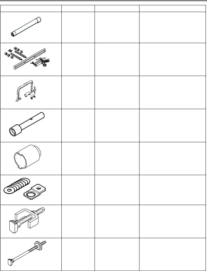
Tool |
Number |
Name |
Use |
|
|
|
|
|
MD998781 |
Flywheel stopper |
Retention of flywheel |
D998781
MD998778 |
Crankshaft sprocket |
Removal of crankshaft sprocket |
|
puller |
and crankshaft sprocket B |
MD998785 |
Sprocket stopper |
Retention of counterbalancer |
|
|
shaft sprocket |
MD998767 |
Tension pulley socket |
Manipulation of tensioner pulley |
|
wrench |
during adjustment of timing belt |
|
|
tension |
D998767 |
|
|
MD998738 |
Set screw |
Retention of tensioner arm and |
|
|
auto-tensioner during timing belt |
|
|
installation |
D998738 |
|
|
MD998713 |
Camshaft oil seal |
Installation of camshaft oil seal |
|
installer |
|
D998713
MD998442 |
Air bleed wire |
Air bleeding of lash adjuster |
11D-12 |
ENGINE OVERHAUL <4G63-Turbo> |
||
|
|||
|
|
SPECIAL TOOLS |
|
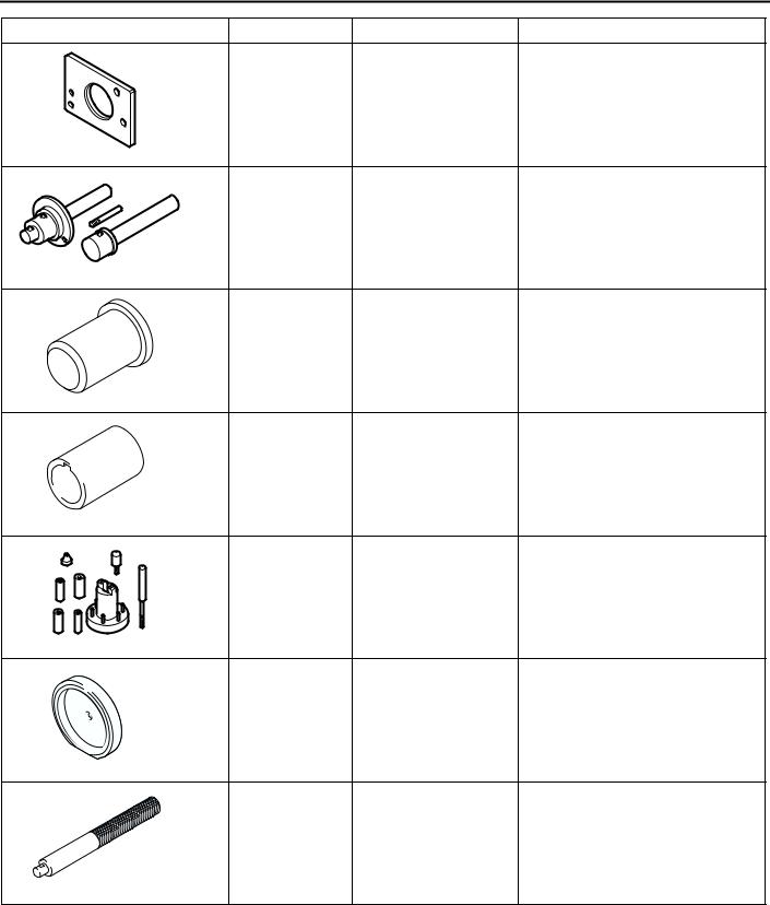
Tool |
Number |
Name |
Use |
|
MB991654 |
Cylinder head bolt |
Removal and installation of |
|
|
wrench |
cylinder head bolts |
|
B991654 |
|
|
|
MD998772 |
Valve spring |
Compression of valve spring |
|
|
compressor |
|
MD998735 |
Valve spring |
Compression of valve spring |
|
compressor |
|
MD998737 |
Valve stem seal |
Installation of valve stem seal |
|
installer |
|
MD998162 |
Plug wrench |
Removal and installation of front |
|
|
case plug cap |
|
|
(Use with MD998783.) |
MD998783 |
Plug wrench retainer Removal and installation of front |
|
case plug cap |
|
(Use with MD998162.) |
MD998371 |
Silent shaft bearing |
Removal of counterbalancer shaft |
|
puller |
front bearing |
MD998372 |
Silent shaft bearing |
Removal of counterbalancer shaft |
|
puller |
front and rear bearings |
|
ENGINE OVERHAUL <4G63-Turbo> |
11D-13 |
|
|
|
SPECIAL TOOLS |
|
Tool |
Number |
Name |
Use |
|
MB991603 |
Silent shaft bearing |
Guide and stopper for removal |
|
|
installer stopper |
and press-fitting of |
|
|
|
counterbalancer shaft rear |
|
|
|
bearing |
|
MD998705 |
Silent shaft bearing |
Press-fitting of counterbalancer |
|
|
installer |
shaft front and rear bearings |
MD998375 |
Crankshaft front oil |
Installation of crankshaft front oil |
|
seal installer |
seal |
MD998285 |
Crankshaft front oil |
Guide for installation of |
|
seal guide |
crankshaft front oil seal |
D998285
MD998780 |
Piston pin setting tool Removal and press-fitting of |
|
piston pin |
MD998776 |
Crankshaft rear oil |
Installation of crankshaft rear oil |
|
seal installer |
seal |
D998776
MB990938 |
Handle |
Installation of crankshaft rear oil |
|
|
seal |
|
|
(Use with MD998776.) |

11D-14 |
ENGINE OVERHAUL <4G63-Turbo> |
|
|
|
ALTERNATOR AND IGNITION SYSTEM |
ALTERNATOR AND IGNITION SYSTEM
REMOVAL AND INSTALLATION
M1113001000701
|
|
|
|
12 |
3.0 ± 0.5 N·m |
|
|
|
|
|
|
|
2 |
1 |
|
|
|
|
|
|
|
10 ± 2 N·m |
|
|
|
|
|
|
|
|
|
|
|
13 |
|
|
|
|
|
|
14 |
13 ± 1 N·m |
|
|
15 |
|
|
|
|
|
|
25 ± 5 N·m |
|
|
3 |
10 |
|
|
|
|
|
44 ± 10 N·m |
|
|
|
|
|
|
|
|
|
|
4 |
|
|
|
|
|
9 |
|
|
|
|
|
22 ± 4 N·m |
|
|
|
|
|
|
|
8 |
|
|
|
7 |
|
|
|
|
44 ± 10 N·m |
23 ± 3 N·m |
|
|
|
|
|
8.8 ± 1.0 N·m |
|
|
||
|
|
|
|
||
|
25 ± 4 N·m |
|
|
|
|
|
79 ± 5 N·m |
|
11 |
|
|
6 |
|
|
|
|
|
24 ± 4 N·m |
|
5 |
|
|
|
|
|
AK305988AC |
|||
|
Removal steps |
|
|
Removal steps (Continued) |
|
1. |
Oil level gauge |
|
|
9. Alternator brace |
|
2. |
O-ring |
|
|
10. Alternator |
|
3. |
Oil level gauge guide |
|
|
11. Crankshaft pulley |
|
4. |
O-ring |
|
|
12. Center cover |
|
5. |
Idler pulley |
|
|
13. Spark plug cable |
|
6. |
Cap |
|
|
14. Ignition coil |
|
7. |
Auto-tensioner assembly |
|
15. Spark plug |
|
|
8. |
Water pump pulley |
|
|
|
|

ENGINE OVERHAUL <4G63-Turbo> |
11D-15 |
SOLENOID AND VACUUM HOSE |
|
SOLENOID AND VACUUM HOSE
REMOVAL AND INSTALLATION
M1113025300074
20 ± 2 N·m
4
5 |
19 ± 3 N·m |
|
8 |
23 ± 4 N·m |
9.0 ± 1.0 N·m
36 ± 6 N·m
11 ± 1 N·m
7
3 |
6 11 ± 1 N·m |
11 ± 1 N·m
2
1
|
|
|
AK400296AB |
|
Removal steps |
|
Removal steps (Continued) |
1. |
Vacuum pipe and hose assembly |
5. |
EGR valve gasket |
2. |
Vacuum pipe and hose assembly |
6. |
Solenoid valve |
3. |
Vacuum pipe and hose assembly |
7. |
Solenoid valve |
4. |
EGR valve |
8. |
Engine hanger |

11D-16 |
ENGINE OVERHAUL <4G63-Turbo> |
|
|
|
TIMING BELT |
TIMING BELT
REMOVAL AND INSTALLATION
|
|
M1113001900867 |
|
|
|
|
|
24 |
3.5 ± 0.5 N·m |
|
|
21 |
28 |
|
|
1 |
|
||
11 ± 1 N·m |
22 |
|
25 |
|
|
|
|
|
20 |
5 6
48 ± 5 N·m
 23
23
|
|
|
|
|
21 ± 4 N·m |
|
|
26 |
|
11 ± 1 N·m |
|
|
12 |
7 |
|
|
|
|
|
|
|
|
|
|
|
|
|||
|
|
23 ± 3 N·m |
|
|
|
27 |
|||
|
|
|
|
|
|
|
|
|
|
|
|
|
|
|
|
32 |
11 ± 1 N·m |
|
|
|
|
|
|
|
|
|
|
|
|
|
|
|
|
11 |
11 ± 1 N·m |
33 |
|
|
|
|
|
|
|
|
|
|
|
|
|
|
|
|
|
167 N·m |
29 |
|
|
|
|
|
2 |
|
|
49 ± 5 N·m |
|
|
|
|
|
|
|
|
|
|
|
|
|
||
|
|
9.0 ± 1.0 N·m |
|
|
|
|
|
||
|
31 |
|
4 |
45 ± 3 N·m |
16 17 |
|
|
|
|
|
|
|
|
19 ± 3 N·m |
|
|
|
|
3 |
|
|
|
|
14 |
|
|
|
|
|
|
|
|
|
|
|
|
|
|
|
|
30 |
|
|
|
|
|
34 |
9 |
|
|
|
|
|
|
|
|
|
||
|
88 ± 10 N·m |
|
|
|
19 |
|
|||
|
|
|
|
|
49 ± 9 N·m |
||||
|
|
|
|
|
|
|
|
|
|
|
|
|
|
|
|
15 |
18 8.8 ± 1.0 N·m |
|
|
|
|
|
|
|
13 |
|
|
|
|
|
|
|
|
|
|
|
|
|
|
|
|
8 |
|
|
10 |
|
|
|
AK305989AB |
|
35 ± 6 N·m |
|
|
54 ± 5 N·m |
|
|
|
||
|
|
|
|
|
|
|
|
|
|
|
|
|
Removal steps |
|
|
<<D>> |
>>I<< |
Removal steps (Continued) |
|
|
|
1. Timing belt front upper cover |
|
12. Crankshaft sprocket |
|||||
|
|
2. Timing belt front lower cover |
|
|
>>I<< |
13. Crankshaft sensing blade |
|||
<<A>> |
>>M<< |
3. Power steering pump bracket |
|
<<E>> |
>>H<< |
14. Tensioner "B" |
|||
4. |
Timing belt |
|
|
15. Timing belt "B" |
|||||
|
>>L<< |
5. |
Tensioner pulley |
|
|
<<F>> |
>>G<< |
16. Counterbalancer shaft sprocket |
|
|
|
6. |
Tensioner arm |
|
|
|
>>F<< |
17. Spacer |
|
|
>>K<< |
7. Auto-tensioner |
|
|
<<G>> |
>>E<< |
18. Crankshaft sprocket "B" |
||
|
|
8. |
Idler pulley |
|
|
|
|
19. Crankshaft key |
|
<<B>> |
>>J<< |
9. |
Crankshaft angle sensor |
|
|
|
20. Breather hose |
||
10. Oil pump sprocket |
|
|
|
|
21. PCV hose |
||||
<<C>> |
>>I<< |
11. Crankshaft bolt |
|
|
|
|
22. PCV valve |
||

ENGINE OVERHAUL <4G63-Turbo> |
11D-17 |
TIMING BELT |
|
Removal steps (Continued)
23.PCV valve gasket
24.Oil filler cap >>D<< 25. Rocker cover
>>D<< 26. Rocker cover gasket "A"
>>C<< |
27. Rocker cover gasket "B" |
28. Semicircular packing |
|
>>B<< 29. Engine support bracket |
|
<<H>> >>A<< |
30. Camshaft sprocket bolt |
31.Camshaft sprocket
32.Timing belt rear cover, right
33.Timing belt rear upper cover, left
34Timing belt rear lower cover, left
REMOVAL SERVICE POINTS <<A>> TIMING BELT REMOVAL
AK202756AB |
1.If the timing belt is to be reused, make an arrow mark with something like chalk on the back of the belt indicating the direction of rotation so it may be reinstalled in the same direction.
Timing marks |
AK304440AB |

 CAUTION
Never remove the timing belt with any piston at the top dead center (TDC). If a piston is at TDC, the exhaust valves of the cylinder are pushed by the exhaust cams, compressing the valve springs. If the belt is removed under this condition, the sprocket will be turned in the reverse direction by the force of the springs, incurring risk of injury.
2.Set the timing mark of the exhaust camshaft sprocket to a point about one tooth before the TDC of the No.1 cylinder piston on compression stroke.
3.Loosen the lock nut of the tensioner pulley, then remove the timing belt.
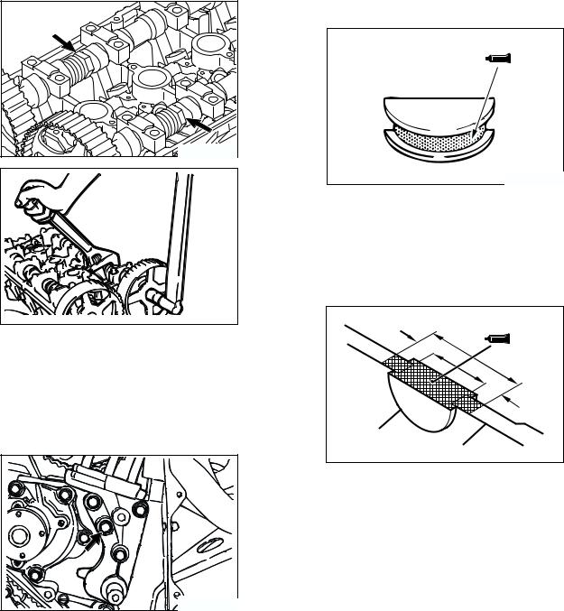
<<B>> OIL PUMP SPROCKET REMOVAL
1. Remove the plug on the left side of cylinder block.
Crosspoint |
screwdriver |
AK202825AD |
2.Insert a crosspoint screwdriver (shank diameter 8 mm) to prevent the counterbalancer shaft from rotating.
3.Remove the flange bolt.
4.Remove the oil pump sprocket.
<<C>> CRANKSHAFT BOLT REMOVAL
MD998781
AK202738AC
1.Hold the drive plate with the special tool Fly wheel stopper (MD998781).
2.Remove the crankshaft bolt.

11D-18 |
ENGINE OVERHAUL <4G63-Turbo> |
|
|
|
TIMING BELT |
<<D>> CRANKSHAFT SPROCKET REMOVAL
MD998778 |
AK304176AB |
Use the special tool Crankshaft sprocket puller (MD998778) if the sprocket is stuck and hard to remove.
<<E>> TIMING BELT "B" REMOVAL
AK300137 |

 CAUTION
Water or oil on the belt shortens its life drastically, so the removed timing belt, sprocket, and tensioner must be free from oil and water. These parts should not be washed or immersed in solvent. Replace parts if contaminated. If there is oil or water on each part, check the front case oil seals, camshaft oil seal and water pump for leaks.
1.Mark the belt running direction for reinstallation.
2.Loosen the tensioner "B" bolt, and then remove the timing belt "B."
<<F>> COUNTERBALANCER SHAFT SPROCKET REMOVAL
MD998785
AK300138AD
1.Use the special tool Sprocket stopper (MD998785) to prevent the counterbalancer shaft sprocket from rotating.
2.Remove the counterbalancer shaft mounting bolt.
<<G>> CRANKSHAFT SPROCKET "B" REMOVAL
MD998778 |
AK300139AD |
|
Use the special tool Crankshaft sprocket puller (MD998778) if the sprocket is stuck and hard to remove.
<<H>> CAMSHAFT SPROCKET BOLT REMOVAL
AK305990AC |
Remove the camshaft sprocket bolt while preventing the camshaft from rotation using a wrench fitted on the hexagonal portion of the camshaft.
ENGINE OVERHAUL <4G63-Turbo> |
11D-19 |
TIMING BELT |
|
INSTALLATION SERVICE POINTS >>A<< CAMSHAFT SPROCKET BOLT INSTALLATION
AK305990AC |
AK304435 |
Tighten the camshaft sprocket bolt to 88 ± 10 N m while preventing the camshaft from rotation using a wrench fitted on the hexagonal portion of the camshaft.
>>B<< ENGINE SUPPORT BRACKET INSTALLATION
AK202743AB |
>>C<< SEMICIRCULAR PACKING INSTALLATION
1.Remove thoroughly the old sealant and FIPG remaining on the semicircular packing, cylinder head, and rocker cover.
AK202860AB
2.Apply sealant to the surface indicated in the drawing of the semicircular packing.
Specified sealant:
3M ATD No.8660 or equivalent
3.Install the semicircular packing on the cylinder head.
10 mm |
|
|
|
|
10 mm |
Semicircular |
|
|
packing |
Cylinder head |
AK304411AB |
|
||
|
|
4.Apply sealant to the area indicated in the drawing of the semicircular packing and cylinder head.
Specified sealant:
3M ATD No.8660 or equivalent
1.Remove thoroughly the old sealant remaining on the indicated bolt and in its hole.
2.Coat the bolt with sealant, then install and tighten it.
Specified sealant:
Mitsubishi Genuine Part No.MD970389 or equivalent
11D-20 |
ENGINE OVERHAUL <4G63-Turbo> |
|
|
|
TIMING BELT |
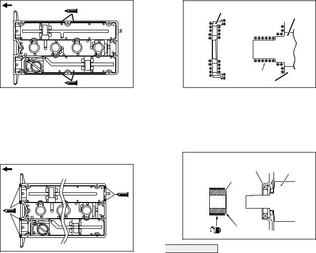
>>D<< ROCKER COVER/ROCKER COVER GASKET "A" INSTALLATION
Timing belt side |
AK304203AB |
1.Apply beads of FIPG on the surfaces of the rocker cover indicated in the drawing.
Specified sealant:
Mitsubishi Genuine Part No.MD970389 or equivalent
2.Install the rocker cover gasket "A" on the rocker cover before the FIPG hardens.
Timing belt side |
AK304204AB |
3.Apply beads of FIPG to the surfaces of the rocker cover indicated in the drawing.
Specified sealant:
Mitsubishi Genuine Part No.MD970389 or equivalent
4.Install the rocker cover on the cylinder head before the FIPG hardens.
>>E<< CRANKSHAFT SPROCKET "B" INSTALLATION
Sprocket "B"
Crankshaft
Degrease |
|
Front case |
AK301828AD |
|
Clean and then degrease the crankshaft sprocket "B" and the sprocket fitting surface of the crankshaft.
NOTE: Degreasing is necessary to prevent lack of frictional coefficient between the mating surfaces.
>>F<< SPACER INSTALLATION
Counter
Oil seal balance shaft
Spacer
Chamfered
AK301298AD

 CAUTION
If the spacer is opposite in direction to that shown in the drawing when installed, it will damage the oil seal lip.
1.Smear slightly oil on the outer surface of the spacer that comes into contact with the oil seal.
2.Install the spacer with the chamfered end toward the oil seal.
|
ENGINE OVERHAUL <4G63-Turbo> |
|
11D-21 |
|
TIMING BELT |
|
|
>>G<< COUNTERBALANCER SHAFT |
Tension section of belt |
||
SPROCKET INSTALLATION |
Tensioner "B" |
||
|
|
Timing |
|
|
|
|
belt "B" |
|
MD998785 |
|
|
|
Tensioner "B" |
|
|
|
centre |
Mounting bolt centre |
|
|
|
AK305992AC |
|
|
3. Make sure that the tensioner "B" center is |
|
AK300138AD |
positioned as shown in the drawing relative to the |
|
|
||
1. Use the special tool Sprocket stopper |
mounting bolt center. |
|
|
||
(MD998785) as shown in the drawing to prevent |
|
|
the counterbalancer shaft sprocket from rotating. |
|
|
2. Tighten the sprocket mounting bolt to 45 ± 3 N m. |
|
|
>>H<< TIMING BELT "B" INSTALLATION |
|
|
Timing |
|
|
marks |
AK304436AB |
|
|
||
|
4. Lift the tensioner "B" with fingers to move it in the |
|
Timing |
direction of the arrow until the tension section of |
|
marks |
the timing belt becomes taut. While keeping the |
|
|
tensioner "B" in this position, tighten its bolt. |
|
AK305991AC |
NOTE: When the bolt is tightened, prevent the |
|
1. Align the timing marks on the crankshaft sprocket |
tensioner "B" shaft from turning. If the shaft turns, |
|
the belt will be overtightened. |
||
"B" and counterbalancer shaft sprocket with the |
5. Make sure that the timing marks on the oil pump |
|
corresponding timing marks on the oil pump case. |
||
case and those of the sprockets are all aligned |
||
2. Install the timing belt "B" on the crankshaft |
||
with each other. |
||
sprocket "B" and counterbalancer shaft sprocket. |
|
|
There should be no slack in the tension section of |
5 – 7 mm |
|
the belt. |
||
|
||
|
AK305993AC |
6.Push a central point of the timing belt "B" tension section lightly with an index to see if it deflects 5 − 7 mm.
 Loading...