


Service Manual
6M60-TL Diesel Engine
For use with the FD80N-FD160N Service Manuals. |
99709-51100 |

(for industrial use)
FOREWORD
This Shop Manual is published for the information and guidance of personnel responsible for maintenance of the Mitsubishi 6M60-TL series diesel engine, and includes procedures for adjustment and maintenance services.
We earnestly look forward to seeing that this manual is made full use of in order to perform correct services with no wastage.
For more details, please consult your nearest authorized Mitsubishi forklift truck dealer.
Kindly note that the specifications and maintenance service figures are subject to change without prior notice in line with improvement which will be effected from time to time in the future.
SEPTEMBER 2006
Applicable models 6M60-TL
GROUP INDEX |
|
|
00 |
GENERAL........................................ |
|
|
11 |
ENGINE............................................ |
|
|
12 |
LUBRICATION................................. |
|
|
13A |
FUEL AND ENGINE CONTROL...... |
|
ELECTRONICALLY CONTROLLED |
|
FUEL SYSTEM .................................. |
|
|
13E |
|
14 |
COOLING......................................... |
|
INTAKE AND EXHAUST ................. |
|
|
15 |
EMISSION CONTROL ..................... |
|
|
17 |
ELECTRICAL................................... |
|
|
54 |
SPECIAL EQUIPMENT ................... |
|
|
61 |

GROUP 00 GENERAL
HOW TO READ THIS MANUAL |
00-2 |
|
|
|
|||
ENGINE NUMBER ............................................................................ |
00-7 |
|
|
PRECAUTIONS FOR MAINTENANCE OPERATION ....................... |
00-8 |
|
|
DIAGNOSTIC CODES |
|
|
|
1. |
Using Multi-Use Tester .............................................................. |
00-17 |
|
2. |
Use of Blinking Warning Lamp for Diagnostic Code .................... |
00-19 |
|
3. |
Up-Time Service Tool Functions .................................................... |
00-21 |
|
4. |
Troubleshooting ............................................................................... |
00-29 |
|
TABLE OF STANDARD TIGHTENING TORQUES .......................... |
00-31 |
|
|
00-1

HOW TO READ THIS MANUAL
This manual consists of the following parts:
•Specifications
•Structure and Operation
•Troubleshooting
•General Inspection and Adjustment
•Service procedures
General Inspection and Adjustment
•Procedures for inspection and adjustment of individual parts and assemblies as mounted on the machine are described including specific items to check and adjust. Specified or otherwise, inspection should be performed for looseness, play, backlash, crack, damage, etc.
Service procedure
•Procedures for servicing components and parts off the machine are described centering on key points in their removal, installation, disassembly, reassembly, inspection, etc.
Inspection
•Check items subject to “acceptable/unacceptable” judgement on the basis of service standards are all given.
•Some routine visual checks and cleaning of some reused parts are not described but must always be included in actual service work.
Caution
•This service manual contains important cautionary instructions and supplementary information under the following four headings which identify the nature of the instructions and information:
DANGER 
WARNING 

CAUTION 
NOTE
Terms and Units
Precautions that should be taken in handling potentially dangerous substances such as battery fluid and coolant additives.
Precautionary instructions, which, if not observed, could result in serious injury or death.
Precautionary instructions, which, if not observed, may result in damage to or destruction of equipment or parts.
Suggestions or supplementary information for more efficient use of equipment or better understandings.
•Front and rear
The forward running direction of the machine is referred to as the front and the reverse running direction is referred to as the rear.
•Left and right
Left hand side and right hand side, when facing the forward running direction of the machine, are respectively left and right.
Standard value
•Standard value dimensions in designs indicating: the design dimensions of individual parts, the standard clearance between two parts when assembled, and the standard value for an assembly part, as the case may be.
Limit
•When the value of a part exceeds this, it is no longer serviceable in respect of performance and strength and must be replaced or repaired.
00-2
00
Tightening torque
•Values are directly specified for out-of-standard tightening torques for bolts and nuts.
•Where there is no specified figure for tightening torque, follow the table covering standard tightening torques.
•When the item is to be tightened in a wet state, “wet” is indicated. Where there is no indication, read it as dry.
Units
•Tightening torques and other parameters are given in SI* units with metric units added in brackets { }. Values in engine specifications, performance curves, and other items taken from official approval documents are given only in metric units.
*SI: Le Système International d’Unités
Example: 390 N·m {40 kgf·m}
Metric unit
SI unit
|
Item |
SI unit {metric unit} |
Conversion factor |
|
|
|
|
|
|
Force |
|
N {kgf} |
9.80665 N {1 kgf} |
|
|
|
|
|
|
Moment of force |
|
N·m {kgf·m} |
9.80665 N·m {1 kgf·m} |
|
|
|
|
|
|
|
Positive pressure |
kPa {kgf/cm2} |
98.0665 kPa {1 kgf/cm2} |
|
Pressure |
Vacuum pressure |
kPa {mmHg} |
0.133322 kPa {1 mmHg} |
|
|
|
|
||
|
Pa {mmH2O} |
9.80665 Pa {1 mmH2O} |
||
|
|
|||
Volume |
|
dm3 {L} |
1 dm3 {1 L} |
|
Heat quantity |
|
J {kcal} |
4186.05 J {1 kcal} |
|
|
|
|
|
|
Heat flow |
|
W {kcal/h} |
1.16279 W {1 kcal/h} |
|
|
|
|
|
|
Power |
|
kW {PS} |
0.7355 kW {1 PS} |
|
|
|
|
|
|
Angle |
|
˚ |
– |
|
|
|
|
|
|
Temperature |
|
˚C |
– |
|
|
|
|
|
|
Electric current |
|
A |
– |
|
|
|
|
|
|
Voltage |
|
V |
– |
|
|
|
|
|
|
Resistance |
|
Ω |
– |
|
|
|
|
|
|
Electric power |
|
W |
– |
|
|
|
|
|
|
|
|
|
|
|
Unit |
SI unit |
Foot-pound unit |
Conversion rate |
|
|
|
|
|
|
Force |
N (Newton) |
lbf |
1 N = 0.2248 lbf |
|
|
|
|
|
|
Moment of force |
N·m |
lbf.ft |
1 N·m = 0.7375 lbf.ft |
|
|
|
|
|
|
Pressure |
kPa (kilopascal) |
lbf/in.2 |
1 kPa = 0.145 lbf/in.2 |
|
1 kPa = 0.2953 in. Hg |
||||
|
|
|
||
|
|
|
|
|
|
L |
gal. |
1 L = 0.2642 gal. (U.S.) |
|
|
|
|
1 L = 0.220 gal. (Imp.) |
|
Volume |
cm3 |
oz |
1 cm3 = 0.033814 oz (U.S.) |
|
|
|
|
1 cm3 = 0.035195 oz (Imp.) |
|
|
cm3 |
cu.in. |
1 cm3 = 0.061023 cu.in. |
|
Power |
kW (kilowatt) |
HP |
1 kW = 1.34 HP |
|
|
|
|
|
|
Temperature |
˚C |
˚F |
t˚C = (1.8t˚C + 32)˚F |
|
|
|
|
|
|
Mass quantity of |
kg |
lb |
1 kg = 2.2046 lb |
|
matter |
g |
oz |
1 g = 0.035274 oz |
|
|
|
|
|
|
Dimension |
m |
ft. |
1 m = 3.2808 ft. |
|
mm |
in. |
1 mm = 0.03937 in. |
||
|
||||
|
|
|
|
|
Stress |
N/cm2 |
lbf/in.2 |
1 N/cm2 = 1.45 lbf/in.2 |
00-3

HOW TO READ THIS MANUAL
Symbol |
|
Denotation |
|
|
|
|
|
|
|
|
Application |
|
|
|
|
|
|
|
|
Remarks |
|||||||||||||||||||||||||||
|
|
|
|
|
|
|
|
|
|
|
|
|
|
|
|
|
|
|
|
|
|
|
|
|
|
|
|
|
|
|
|
|
|
|
|
|
|
|
|
|
|
|
|
|
|
|
|
|
|
|
|
|
|
|
|
|
|
|
|
|
|
|
Parts not tightened to standard torques |
|
Specified values shown in table |
||||||||||||||||||||||||||||||
|
|
|
|
|
|
|
|
|
|
|
|
|
|
|
|
See Table of Standard Tightening Torques for |
|||||||||||||||||||||||||||||||
|
|
|
|
|
Tightening torque |
|
(standard torques specified where neces- |
|
|||||||||||||||||||||||||||||||||||||||
|
|
|
|
|
|
|
parts for which no tightening torques are speci- |
||||||||||||||||||||||||||||||||||||||||
|
|
|
|
|
|
|
|
|
|
|
|
|
|
|
sary for servicing) |
|
|||||||||||||||||||||||||||||||
|
|
|
|
|
|
|
|
|
|
|
|
|
|
|
|||||||||||||||||||||||||||||||||
|
|
|
|
|
|
|
|
|
|
|
|
|
|
|
|
fied. |
|||||||||||||||||||||||||||||||
|
|
|
|
|
|
|
|
|
|
|
|
|
|
|
|
|
|
|
|
|
|
|
|
|
|
|
|
|
|
|
|
|
|
|
|||||||||||||
|
|
|
|
|
|
|
|
|
|
|
|
|
|
|
|
|
|
|
|
|
|
|
|
|
|
|
|
|
|
|
|
|
|
|
|
|
|
|
|
|
|
|
|
|
|
|
|
|
|
|
|
|
Locating pin |
|
Parts to be positioned for installation |
|
|
|
|
|
|
|
|
|
|
|
|
|
|
||||||||||||||||||||||||||
|
|
|
|
|
|
|
|
|
|
|
|
|
|
|
|
|
|
|
|
|
|
|
|
|
|
|
|
|
|
|
|
|
|
|
|
|
|
|
|
|
|
|
|
|
|
|
|
|
|
|
|
|
Non-reusable parts |
|
Parts not to be reused |
|
|
|
|
|
|
|
|
|
|
|
|
|
|
||||||||||||||||||||||||||
|
|
|
|
|
|
|
|
|
|
|
|
|
|
|
|
|
|
|
|
|
|
|
|
|
|
|
|
|
|
|
|
|
|
|
|
|
|
|
|
|
|
|
|
|
|
|
|
|
|
|
|
|
Lubricant and/or |
|
Parts to be coated with lubricant or sealant |
|
Necessary lubricant and/or sealant, quantity re- |
||||||||||||||||||||||||||||||||||||||
|
|
|
|
|
sealant |
|
for assembly or installation |
|
quired, etc. are specified in table. |
||||||||||||||||||||||||||||||||||||||
|
|
|
|
|
|
|
|
|
|
|
|
|
|
|
|
|
|
|
|
|
|
|
|
|
|
|
|
|
|
|
|
|
|
|
|
|
|
|
|
|
|
|
|
|
|
|
|
|
|
|
|
|
Special tool |
|
Parts for which special tools are required for |
|
Tool name/shape and part number are shown in |
||||||||||||||||||||||||||||||||||||||
|
|
|
|
|
|||||||||||||||||||||||||||||||||||||||||||
|
|
|
|
|
|
service operation |
|
table. |
|||||||||||||||||||||||||||||||||||||||
|
|
|
|
|
|
|
|
|
|
|
|
|
|
|
|
||||||||||||||||||||||||||||||||
|
|
|
|
|
|
|
|
|
|
|
|
|
|
||||||||||||||||||||||||||||||||||
|
|
|
|
|
|
|
|
|
|
|
|
|
|
|
|
|
|
|
|
|
|
|
|
|
|
|
|
|
|
|
|
|
|
|
|
|
|
|
|
|
|
|
|
|
|
|
|
|
*a |
Associated part |
|
Parts associated with those removed/disas- |
|
|
|
|
|
|
|
|
|
|
|
|
|
|
|||||||||||||||||||||||||||||
|
|
sembled for servicing |
|
|
|
|
|
|
|
|
|
|
|
|
|
|
|||||||||||||||||||||||||||||||
|
|
|
|
|
|
|
|
|
|
|
|
|
|
|
|
|
|
|
|
|
|
|
|
|
|
|
|
|
|||||||||||||||||||
|
|
|
|
|
|
|
|
|
|
|
|
|
|
|
|
|
|
|
|
|
|
|
|
|
|
|
|
|
|
|
|
|
|
|
|
|
|
|
|
|
|
|
|
|
|
|
|
|
|
|
|
|
|
|
|
|
|
|
|
|
|
|
|
|
|
|
|
|
|
|
|
|
|
|
|
|
|
|
|
|
|
|
|
|
|
|
|
|
|
|
|
|
|
|
|
|
|
|
|
|
|
|
|
|
|
|
|
|
|
|
|
|
|
|
|
|
|
|
|
|
|
|
|
|
|
|
|
|
|
|
|
|
|
|
|
|
|
|
|
|
|
|
|
|
|
|
|
|
|
|
|
|
|
|
|
|
|
|
|
|
|
|
|
|
|
|
|
|
|
|
|
|
|
|
|
|
|
|
|
|
|
|
|
|
|
|
|
|
|
|
|
|
|
|
|
|
|
|
|
|
|
|
|
|
|
|
|
|
|
|
|
|
|
|
|
|
|
|
|
|
|
|
|
|
|
|
|
|
|
|
|
|
|
|
|
|
|
|
|
|
|
|
|
|
|
|
|
|
|
|
|
|
|
|
|
|
|
|
|
|
|
|
|
|
|
|
|
|
|
|
|
|
|
|
|
|
|
|
|
|
|
|
|
|
|
|
|
|
|
|
|
|
|
|
|
|
|
|
|
|
|
|
|
|
|
|
|
|
|
|
|
|
|
|
|
|
|
|
|
|
|
|
|
|
|
|
|
|
|
|
|
|
|
|
|
|
|
|
|
|
|
|
|
|
|
|
|
|
|
|
|
|
|
|
|
|
|
|
|
|
|
|
|
|
|
|
|
|
|
|
|
|
|
|
|
|
|
|
|
|
|
|
|
|
|
|
|
|
|
|
|
|
|
|
|
|
|
|
|
|
|
|
|
|
|
|
|
|
|
|
|
|
|
|
|
|
|
|
|
|
|
|
|
|
|
|
|
|
|
|
|
|
|
|
|
|
|
|
|
|
|
|
|
|
|
|
|
|
|
|
|
|
|
|
|
|
|
|
|
|
|
|
|
|
|
|
|
|
|
|
|
|
|
|
|
|
|
|
|
|
|
|
|
|
|
|
|
|
|
|
|
|
|
|
|
|
|
|
|
|
|
|
|
|
|
|
|
|
|
|
|
|
|
|
|
|
|
|
|
|
|
|
|
|
|
|
|
|
|
|
|
|
|
|
|
|
|
|
|
|
|
|
|
|
|
|
|
|
|
|
|
|
|
|
|
|
|
|
|
|
|
|
|
|
|
|
|
|
|
|
|
|
|
|
|
|
|
|
|
|
|
|
|
|
|
|
|
|
|
|
|
|
|
|
|
|
|
|
|
|
|
|
|
|
|
|
|
|
|
|
|
|
|
|
|
|
|
|
|
|
|
|
|
|
|
|
|
|
|
|
|
|
|
|
|
|
|
|
|
|
|
|
|
|
|
|
|
|
|
|
|
|
|
|
|
|
|
|
|
|
|
|
|
|
|
|
|
|
|
|
|
|
|
|
|
|
|
|
|
|
|
|
|
|
|
|
|
|
|
|
|
|
|
|
|
|
|
|
|
|
|
|
|
|
|
|
|
|
|
|
|
|
|
|
|
|
|
|
|
|
|
|
|
|
|
|
|
|
|
|
|
|
|
|
|
|
|
|
|
|
|
|
|
|
|
|
|
|
|
|
|
|
|
|
|
|
|
|
|
|
|
|
|
|
|
|
|
|
|
|
|
|
|
|
|
|
|
|
|
|
|
|
|
|
|
|
|
|
|
|
|
|
|
|
|
|
|
|
|
|
|
|
|
|
|
|
|
|
|
|
|
|
|
|
|
|
|
|
|
|
|
|
|
|
|
|
|
|
|
|
|
|
|
|
|
|
|
|
|
|
|
|
|
|
|
|
|
|
|
|
|
|
|
|
|
|
|
|
|
|
|
|
|
|
|
|
|
|
|
|
|
|
|
|
|
|
|
|
|
|
|
|
|
|
|
|
|
|
|
|
|
|
|
|
|
|
|
|
|
|
|
|
|
|
|
|
|
|
|
|
|
|
|
|
|
|
|
|
|
|
|
|
|
|
|
|
|
|
|
|
|
|
|
|
|
|
|
|
|
|
|
|
|
|
|
|
|
|
|
|
|
|
|
|
|
|
|
|
|
|
|
|
|
|
|
|
|
|
|
|
|
|
|
|
|
|
|
|
|
|
|
|
|
|
|
|
|
|
|
|
|
|
|
|
|
|
|
|
|
|
|
|
|
|
|
|
|
|
|
|
|
|
|
|
|
|
|
|
|
|
|
|
|
|
|
|
|
|
|
|
|
|
|
|
|
|
|
|
|
|
|
|
|
|
|
|
|
|
|
|
|
|
|
|
|
|
|
|
|
|
|
|
|
|
|
|
|
|
|
|
|
|
|
|
|
|
|
|
|
|
|
|
|
|
|
|
|
|
|
|
|
|
|
|
|
|
|
|
|
|
|
|
|
|
|
|
|
|
|
|
|
|
|
|
|
|
|
|
|
|
|
|
|
|
|
|
|
|
|
|
|
|
|
|
|
|
|
|
|
|
|
|
|
|
|
|
|
|
|
|
|
|
|
|
|
|
|
|
|
|
|
|
|
|
|
|
|
|
|
|
|
|
|
|
|
|
|
|
|
|
|
|
|
|
|
|
|
|
|
|
|
|
|
|
|
|
|
|
|
|
|
|
|
|
|
|
|
|
|
|
|
|
|
|
|
|
|
|
|
|
|
|
|
|
|
|
|
|
|
|
|
|
|
|
|
|
|
|
|
|
|
|
|
|
|
|
|
|
|
|
|
|
|
|
|
|
|
|
|
|
|
|
|
|
|
|
|
|
|
|
|
|
|
|
|
|
|
|
|
|
|
|
|
|
|
|
|
|
|
|
|
|
|
|
|
|
|
|
|
|
|
|
|
|
|
|
|
|
|
|
|
|
|
|
|
|
|
|
|
|
|
|
|
|
|
|
|
|
|
|
|
|
|
|
|
|
|
|
|
|
|
|
|
|
|
|
|
|
|
|
|
|
|
|
|
|
|
|
|
|
|
|
|
|
|
|
|
|
|
|
|
|
|
|
|
|
|
|
|
|
|
|
|
|
|
|
|
|
|
|
|
|
|
|
|
|
|
|
|
|
|
|
|
|
|
|
|
|
|
|
|
|
|
|
|
|
|
|
|
|
|
|
|
|
|
|
|
|
|
|
|
|
|
|
|
|
|
|
|
|
|
|
|
|
|
|
|
|
|
|
|
|
|
|
|
|
|
|
|
|
|
|
|
|
|
|
|
|
|
|
|
|
|
|
|
|
|
|
|
|
|
|
|
|
|
|
|
|
|
|
|
|
|
|
|
|
|
|
|
|
|
|
|
|
|
|
|
|
|
|
|
|
|
|
|
|
|
|
|
|
|
|
|
|
|
|
|
|
|
|
|
|
|
|
|
|
|
|
|
|
|
|
|
|
|
|
|
|
|
|
|
|
|
|
|
|
|
|
|
|
|
|
|
|
|
|
|
|
|
|
|
|
|
|
|
|
|
|
|
|
|
|
|
|
|
|
|
|
|
|
|
|
|
|
|
|
|
|
|
|
|
|
|
|
|
|
|
|
|
|
|
|
|
|
|
|
|
|
|
|
|
|
|
|
|
|
|
|
|
|
|
|
|
|
|
|
|
|
|
|
|
|
|
|
|
|
|
|
|
|
|
|
|
|
|
|
|
|
|
|
|
|
|
|
|
|
|
|
|
|
|
|
|
|
|
|
|
|
|
|
|
|
|
|
|
|
|
|
|
|
|
|
|
|
|
|
|
|
|
|
|
|
|
|
|
|
|
|
|
|
|
|
|
|
|
|
|
|
|
|
|
|
|
|
|
|
|
|
|
|
|
|
|
|
|
|
|
|
|
|
|
|
|
|
|
|
|
|
|
|
|
|
|
|
|
|
|
|
|
|
|
|
|
|
|
|
|
|
|
|
|
|
|
|
|
|
|
|
|
|
|
|
|
|
|
|
|
|
|
|
|
|
|
|
|
|
|
|
|
|
|
|
|
|
|
|
|
|
|
|
|
|
|
|
|
|
|
|
|
|
|
|
|
|
|
|
|
|
|
|
|
|
|
|
|
|
|
|
|
|
|
|
|
|
|
|
|
|
|
|
|
|
|
|
|
|
|
|
|
|
|
|
|
|
|
|
|
|
|
|
|
|
|
|
|
|
|
|
|
|
|
|
|
|
|
|
|
|
|
|
|
|
|
|
|
|
|
|
|
|
|
|
|
|
|
|
|
|
|
|
|
|
|
|
|
|
|
|
|
|
|
|
|
|
|
|
|
|
|
|
|
|
|
|
|
|
|
|
|
|
|
|
|
|
|
|
|
|
|
|
|
|
|
|
|
|
|
|
|
|
|
|
|
|
|
|
|
|
|
|
|
|
|
|
|
|
|
|
|
|
|
|
|
|
|
|
|
|
|
|
|
|
|
|
|
|
|
|
|
|
|
|
|
|
|
|
|
|
|
|
|
|
|
|
|
|
|
|
|
|
|
|
|
|
|
|
|
|
|
|
|
|
|
|
|
|
|
|
|
|
|
|
|
|
|
|
|
|
|
|
|
|
|
|
|
|
|
|
|
|
|
|
|
|
|
|
|
|
|
|
|
|
|
|
|
|
|
|
|
|
|
|
|
|
|
|
|
|
|
|
|
|
|
|
|
|
|
|
|
|
|
|
|
|
|
|
|
|
|
|
|
|
|
|
|
|
|
|
|
|
|
|
|
|
|
|
|
|
|
|
|
|
|
|
|
|
|
|
|
|
|
|
|
|
|
|
|
|
|
|
|
|
|
|
|
|
|
|
|
|
|
|
|
|
|
|
|
|
|
|
|
|
|
|
|
|
|
|
|
|
|
|
|
|
|
|
|
|
|
|
|
|
|
|
|
|
|
|
|
|
|
|
|
|
|
|
|
00-4

00
00-5

HOW TO READ THIS MANUAL
How to Use Diagnostic Codes <Electronically Controlled Fuel System (Gr13E)>
|
|
|
|
TROUBLESHOOTING |
|
|
||||
|
|
|
1. |
Diagnostic Procedure |
|
|
||||
|
|
|
2. |
Diagnostic Precautions |
|
|
||||
|
This section suggests areas to |
|
|
|||||||
|
inspect for each diagnostic |
|
|
3. |
Inspections Based On Diagnostic Codes |
|
|
|
|
|
|
|
|
|
|
|
|
||||
|
code. |
|
|
4. |
Multi-use Tester Service Data |
|
|
|
|
|
|
|
|
|
|
|
|
|
|||
|
|
|
5. |
Actuator Tests Performed Using Multi-use Tester |
|
|
||||
|
|
|
|
|||||||
|
|
|
6. |
Inspections Performed At Electronic Control |
|
|
|
|||
|
|
|
|
|
|
|||||
|
|
|
|
|
Unit Connectors |
|
|
|||
|
|
|
|
|
|
|
|
|
|
|
There are the diagnostic code and message displayed on Multi-Use Tester. Numerical values in parenthesis are added only when a diagnostic code indicated in the Multi-Use Tester display differs from the code indicated by the number of warning lamp flashes.
P125A: Common Rail Pressure M/V1 (high) (warning lamp flashes: 63)
Code generation criteria |
MPROP1 (rail pressure control valve) voltage is above standard valve. |
|
|
|
|
||||
|
|
|
|
|
|
|
|
|
|
Resetability |
System recovers (power is re-supplied to electronic control unit) if signal |
|
|
|
|
||||
becomes normal when starter switch is turned OFF → ON. |
|
|
|
|
|||||
|
|
|
|
|
|
||||
|
|
|
|
|
|
|
|
|
|
Electronic control unit control |
• Engine is stopped. |
|
|
|
|
||||
• Exhaust gas recirculation control is stopped. |
|
|
|
|
|||||
|
|
|
|
|
|
||||
|
|
|
|
|
|
|
|
|
|
In- |
Service data |
0C: Difference Common Rail Pressure |
|
|
|
|
|
|
|
|
|
|
|
|
|
||||
|
|
|
|
|
|
|
|
|
|
|
|
|
|
|
|
|
|
|
|
Actuator test |
B9: Fuel Leak Check |
|
|
|
|
||||
spec- |
|
|
|
|
|||||
Electronic control unit |
|
|
|
|
|
|
|
|
|
tion |
08 : Resistance of MPROP (rail pressure control valve) |
|
|
|
|
|
|
||
connector |
|
|
|
|
|
|
|||
item |
|
|
|
|
|
|
|
|
|
|
|
|
|
|
|
|
|
|
|
|
Electrical part |
#574: MPROP1 (rail pressure control valve) |
|
|
|
|
|
||
|
|
|
|
|
|
||||
|
|
|
|
|
|
|
|
|
|
|
|
|
|
|
|
|
|
|
|
Refer to “Inspection of Electrical
Equipment.”
The contents of this manual include functions and parts that are not used in your truck depending on the truck specifications. Please refer to the chassis service manual for the details.
00-6

ENGINE NUMBER |
00 |
|
|
•Serial engine numbers are assigned to the engines in manufacturing sequence. Every engine has its own number. These numbers are required for registration and related inspection of the vehicle.
•An engine nameplate indicates the following item.
• Engine model
00-7
PRECAUTIONS FOR MAINTENANCE OPERATION
•Before performing service operations, inquire into the customer’s complaints and ascertain the conditions by checking the total distance traveled, the conditions under which the vehicle is operated, and other relevant factors about the vehicle. And note the necessary information. This information will help you to service the truck efficiently.
•Check the location of the fault, and identify its cause. Based on your findings, determine whether parts must be removed or disassembled. Then, follow the service procedure given in this manual.
• Prepare all the general and special tools necessary for the job.
WARNING 
•Special tools must be used wherever specified in this manual. Do not attempt to use other tools since they could cause injuries and/or truck damage.
•Take extreme care when removing/installing heavy items such as engine, transmission and axle. When lifting heavy items using a cable etc., observe the following precautions.
• Identify the weight of the item being lifted. Use a cable that is strong enough to support the weight.
•If lifting eyes are not provided on the item being lifted, tie a cable around the item taking into account the item’s center of gravity.
• Never work in shoes that have oily soles.
When working with a partner or in a group, use pre-arranged signals and pay constant attention to safety. Be careful not to touch switches and levers unintentionally.
•Inspect for oil leakage etc. before washing the vehicle. If the order is reversed, any oil leakage or fault that may exist could go unnoticed during inspection.
00-8

00
• Prepare replacement parts ready for installation.
•Oil seals, packings, O-rings and other rubber parts, gaskets, and split pins must be replaced with new ones after removal. Use only genuine MITSUBISHI replacement parts.
•When disassembling parts, visually check them for wear, cracks, damage, deformation, deterioration, rust, corrosion, defective rotation, fatigue, clogging and any other possible defect.
•To facilitate correct reassembly of parts, make alignment marks on them before disassembly and arrange disassembled parts neatly. Make punch marks and other alignment marks where they will not detract from parts’ functionality and appearance.
•After removing parts from the vehicle, cover the area to keep it free of dust.
CAUTION 
•Be careful not to mix up identical parts, similar parts and parts that have left/right alignments.
•Keep new replacement parts and original (removed) parts separately.
•Apply the specified oil or grease to U-seals, oil seals, dust seals and bearings before reassembly.
•Always use the specified oils and greases when performing inspection or replacement. Immediately wipe away any excess oil or grease with a rag.
00-9

PRECAUTIONS FOR MAINTENANCE OPERATION
•Wear safety goggles when using a grinder or welder. Wear gloves when necessary, and watch out for sharp edges and other items that might wound your hands.
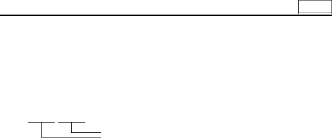
•Before working on the electrical system, disconnect the (–) battery cable to prevent short circuits.
CAUTION 
•Make sure the starter switch and lighting switches are OFF before disconnecting or connecting battery cable. Semiconductor components may otherwise be damaged.
•Carefully handle sensors relays, and other items that are sensi-
tive to shock and heat. Do not remove or paint the cover of any control unit.
•When separating connectors, grasp the connectors themselves rather than the harnesses.
• To separate locking connectors, first push them in the direction of the arrows. To reconnect locking connectors, push them together until they click.
•Before washing the vehicle, cover electrical parts to keep them dry. (Use plastic sheets or the like.) Keep water away from harness connectors and sensors and immediately wipe off any water that gets on them.
00-10
00
•When applying a voltage to a part for inspection purposes, check that the (+) and (–) cables are connected properly then gradually increase the voltage from zero. Do not exceed the specified voltage.
Remember that control units and sensors do not necessarily operate on the battery voltage.
1. Handling Precautions for Electric Circuits
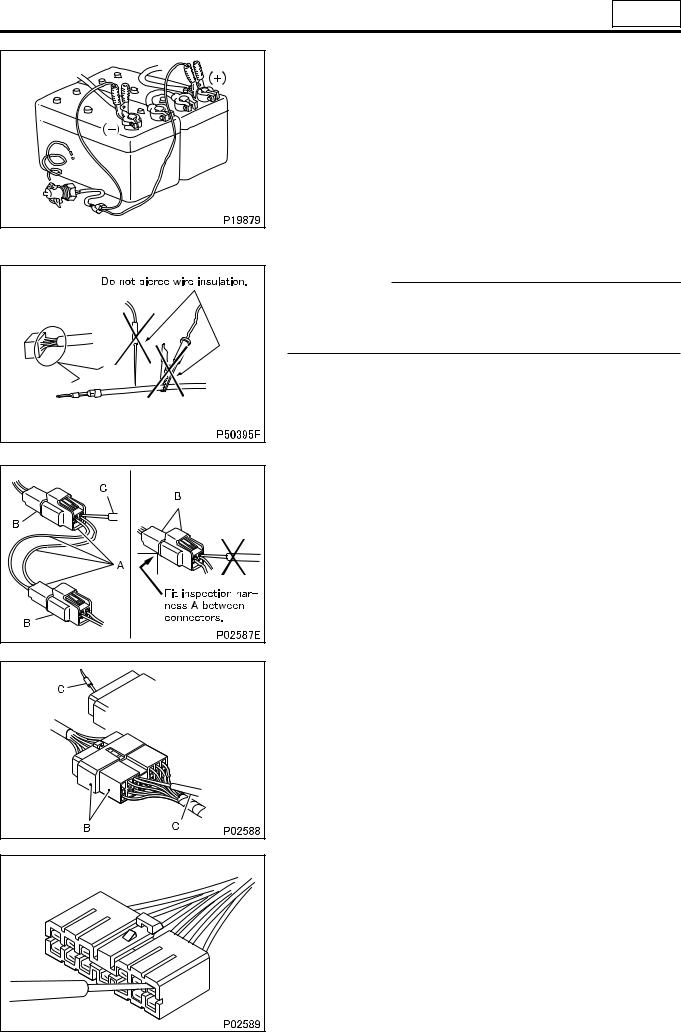
CAUTION 
•Do not pierce wire insulation with test probes or alligator clips when performing electrical inspections. Piercing the
wire harness will cause corrosion.
1.1 Inspection of harnesses
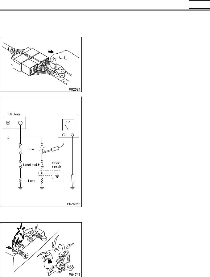
(1) Inspections with connectors fitted together
(1.1) Waterproof connectors
• Connect an inspection harness and connector A between the connectors B of the circuit to be inspected. Perform the inspection by applying a test probe C to the connectors of the inspection harness. Do not insert the test probe C into the wire-entry sides of the waterproof connectors since this would damage their waterproof seals and lead to rust.
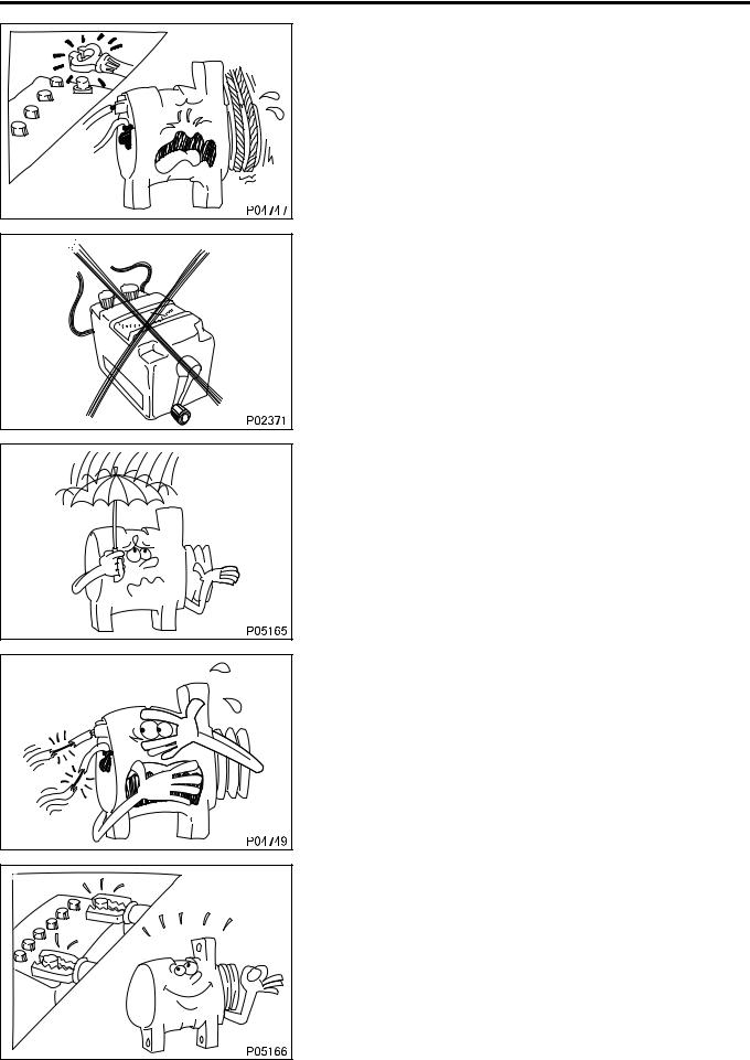
(1.2) Non-waterproof connectors
• Perform the inspection by inserting a test probe C into the wireentry sides of the connectors. An extra-narrow probe is required for control unit connectors, which are smaller than other types of connector. Do not force a regular-size probe into control unit connectors since this would cause damage.
(2) Inspections with connectors separated
(2.1) Inspections on female terminals
• Perform the inspection by carefully inserting a test probe into the terminals. Do not force the test probe into the terminals since this could deform them and cause poor connections.
00-11

PRECAUTIONS FOR MAINTENANCE OPERATION
(2.2) Inspections on male terminals
• Perform the inspection by applying test probes directly to the pins.
.
CAUTION
• Be careful not to short-circuit pins together with the test probes. With control unit connectors, short-circuiting of pins can cause damage to the control unit’s internal circuitry.
•When using a multimeter to check continuity, do not allow the test probes to touch the wrong terminals.
1.2 Inspection of connectors
(1) Visual inspection
• Check that the connectors are fitted together securely.
• Check whether wires have been separated from their terminals due to pulling of the harness.
• Check that male and female terminals fit together tightly.
00-12
00
•Check for defective connections caused by loose terminals, by rust on terminals, or by contamination of terminals by foreign substances.
(2) Checking for loose terminals
•If connector terminal retainers become damaged, male and female terminals may not mate with each other when the connector bodies are fitted together. To check for such terminals, gently pull each wire and see whether any terminals slip out of their connector housings.
1.3 Inspections when a fuse blows
•Remove the fuse, then measure the resistance between ground and the fuse’s load side.
Next, close the switch of each circuit connected to the fuse. If the resistance measurement between any switch and ground is zero, there is a short circuit between the switch and the load. If the resistance measurement is not zero, the circuit is not currently short-circuited; the fuse probably blew due to a momentary short circuit.
•The main causes of short circuits are as follows:
•Harnesses trapped between chassis parts
•Harness insulation damage due to friction or heat
•Moisture in connectors or circuitry
•Human error (accidental short-circuiting of components)
2.Service Precautions for Alternators
•When servicing alternators, observe the following precautions:
•Never reverse the polarity of battery connections.
If the polarity of the battery connections were to be reversed, a large current would flow from the battery to the alternator, damaging the diodes and regulator.
00-13
PRECAUTIONS FOR MAINTENANCE OPERATION
•Never disconnect the battery cables with the engine running. Disconnection of the battery cables during engine operation would cause a surge voltage, leading to deterioration of the diodes and regulator.
•Never perform inspections using a high-voltage multimeter. The use of a high-voltage multimeter could damage the diodes and regulator.
•Keep alternators dry.
Water on alternators can cause internal short circuits and dam-
age.
•Never operate an alternator with the B and L terminals short-cir- cuited. Operation with the B and L terminals connected together would damage the diode trio.
•Disconnect the battery cables before quick-charging the battery with a quick charger.
Unless the battery cables are disconnected, quick-charging can damage the diodes and regulator.
00-14
00
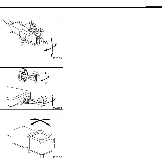
3. Intermittent Faults
•An intermittent fault typically occurs only under certain operating conditions. Once these conditions have been identified, the cause of the intermittent fault can be ascertained easily. First, ask the customer about the vehicle operating conditions and
weather conditions under which the fault occurs. Also ask about the frequency with which the fault occurs and about the fault symptoms. Then, reproduce the fault based on this information. In accordance with the conditions under which the fault occurs, determine whether the fault is caused by vibration, heat or other factors. if vibration is a possible factor, see if the fault can be reproduced by performing the following checks on individual connectors and other parts:
•Gently move connectors up and down and to left and right.
•Gently move wiring harnesses up and down and to left and
right.
•Gently wiggle sensors and other devices by hand.
•Gently wiggle wiring harnesses on suspension systems and other moving parts.
•Connectors and other parts to be checked are those included or
given as likely fault locations in inspection procedures corresponding to diagnostic codes and/or fault symptoms.
00-15

PRECAUTIONS FOR MAINTENANCE OPERATION
4. Precautions for Arc Welding
•When arc welding is performed, current from the welder flows to ground via the machine metal parts. Unless appropriate steps are taken, this current can damage control units, other electrical devices and wiring harnesses. And any electrical device near the point on the vehicle to which the (–) cable of the welder is connected, might be largely damaged.
•The current of the welder will flow backward through the battery’s (–) cable and damage the battery and electrical systems directly connected to the battery. Be sure to disconnect the bat-
tery’s (–) cable in the following procedure.
• Turn the battery switch to the LOCK position.
• Turn the starter switch to the LOCK position.
• Disconnect the battery’s (–) cable.
• Cover all parts of the machine that may be damaged by welding sparks.
•Connect the welder’s (–) cable to the machine as close as possible to the area being welded.
•Set the welding current in accordance with the part being welded.
00-16
DIAGNOSTIC CODES |
00 |
|
|
NOTE:
The Multi-Use tester tool will not be used to service the 6M60-TL diesel engine at this time. Please disregard the Multi-Use Tester information. The Up-Time 2.41 or later software must be used to service the 6M60-TL diesel engine.
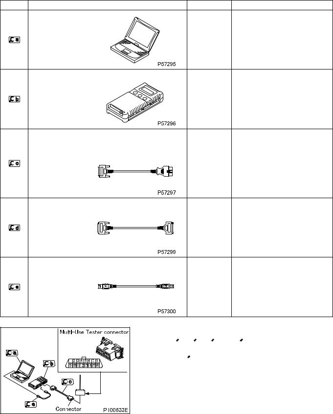
1. Using Multi-Use Tester
1.1 Connecting Multi-Use Tester
Special tools
Mark |
Tool name and shape |
Part No. |
Application |
|
|
FMSi-E06-1 |
|
|
PC |
(Multi-Use |
Data transmission to/from V.C.I. |
|
Tester-III ver- |
||
|
|
|
|
|
|
sion) |
|
V.C.I. |
N/A |
Data transmission between electronic |
|
control unit and PC |
|||
|
|
Multi-Use Tester har- |
MH062928 |
Power supply to V.C.I. and communi- |
|
cation with electronic control unit |
|||
|
|||
ness A |
|
||
|
|
Multi-Use Tester test |
MH062931 |
|
|
(1 m) |
Multi-Use Tester test harness A |
||
harness D |
|||
MH062951 |
extension |
||
(used for extension) |
|||
(2 m) |
|
||
|
|
USB cable |
MB991827 |
Communication between V.C.I. and |
|
PC |
|||
|
|
•Move the starter switch to the LOCK position.
•Connect  ,
,  ,
,  and
and  as illustrated.
•Connect the Multi-Use Tester connector on the vehicle with the
connector of  .
.
00-17
DIAGNOSTIC CODES
• Use  to extend the cable if
  is not long enough such as when using Multi-Use Tester outside the vehicle.
1.2 Access and Clearing of Stored Diagnostic Code
(1) Difference of diagnostic code
• There are two types of diagnostic codes – present code and past code.
(1.1)
(1.2) Present diagnostic code
•Fault developed in the machine after the starter switch is set to ON is indicated by corresponding diagnostic code.
•The fault warning lamp is lit at the same time.
(1.3) Past diagnostic code
•Past fault developed in the machine is indicated by corresponding diagnostic code stored in the memory of the electronic control unit.
•With the machine restored to its normal condition or the starter switch turned from OFF to ON after inspection or repair against present diagnostic codes, the present diagnostic code is stored as past diagnostic codes in the memory of the electronic control unit.
•The warning lamp is not lit because the indicated fault is not present one.
(2) |
Access of diagnostic code |
|
• |
Set the starter switch to ON. |
|
• |
Operate the Multi-Use Tester for a display of necessary diagnostic codes stored in the memory of the electronic |
|
|
control unit and identify the location of the fault. |
|
(3) |
Clearing of diagnostic code |
|
•Set the starter switch to ON (the engine not to be started).
•Operate the Multi-Use Tester to delete all the diagnostic codes stored in the memory of the electronic control unit.
00-18

00
2. Use of Blinking Warning Lamp for Diagnostic Code
• Using the diagnostic and memory clear switches, display diagnostic codes.
CAUTION 
•Opening the memory clear switch followed by its reconnection will erase the stored diagnostic codes from the memory. To avoid inadvertently erasing necessary codes, be sure to read well the procedure described below before handling diagnostic codes.
2.1 Reading diagnostic codes
• To read a diagnostic code, observe how may times the warning lamp flashes and how long each illumination lasts.
•The duration of illumination differs between the first and second digits.
• Second digit: 1.2 sec.
• First digit: 0.4 sec.
•A diagnostic code consists of the flashing of second digit and the flashing of first digit in that order. If a diagnostic code has “0” in the second digit, only the first digit will be displayed.
• The same diagnostic code will be displayed 3 times in a row before moving to the display of the next code.
• After the last diagnostic code is displayed, the first code will be displayed again 3 times in a row and then the subsequent codes. This will be repeated.
2.2 Present diagnostic codes
• Turn the starter switch ON.
• Remove the diagnostic switch.
• Diagnostic codes will be displayed (flashing of the warning lamp).
• When the diagnostic switch is connected, electronic control unit will immediately stop (terminate) displaying diagnostic codes.
2.3 Present and past diagnostic codes
• Turn the starter switch to the ON position.
• Open the diagnostic switch.
• Open the memory clear switch.
• The corresponding warning lamp will display diagnostic codes by flashing.
• Turn the starter switch to the OFF position, connect the memory clear switch and then connect the diagnostic switch. The electronic control unit terminates (exits) the diagnostic code displaying mode.
00-19
DIAGNOSTIC CODES
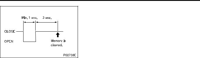
2.4 Erasing diagnostic codes
• Turn the starter switch to the ON position (do not start the engine).
• Open the memory clear switch and reconnect it; all diagnostic codes stored in electronic control unit memory will be erased. To erase diagnostic code after opening the memory clear switch, turn the starter switch to the OFF position and then reconnect the memory clear switch.
00-20

TABLE OF STANDARD TIGHTENING TORQUES |
00 |
|
|
3. Up-Time Service Tool Functions
3.1 Menu
Monitor menu
•Input Monitor
Indicates the input values of the controllers.
•Output Monitor
Indicates the output values of the controllers.
•Custom Monitor
Indicates the input/output values of the item selected.
•Fault Status
Indicates all error codes occurring.
•Fault History
Indicates the fault data, such as the error codes and hour meter data, stored in the controller.
Tool menu
•Set-up Option
Indicates or sets the Setup Option data.
•Oscilloscope
Graphs the input/output values. The oscillograph can be stored as data.
•Active Test
Outputs the signal forcibly to check the operation of the equipment selected.
•Connection Change
Designates the controller operated by the service tool and the controller connected to it.
•Firmware Update
Updates the firmware of the controller connected.
212338
00-21
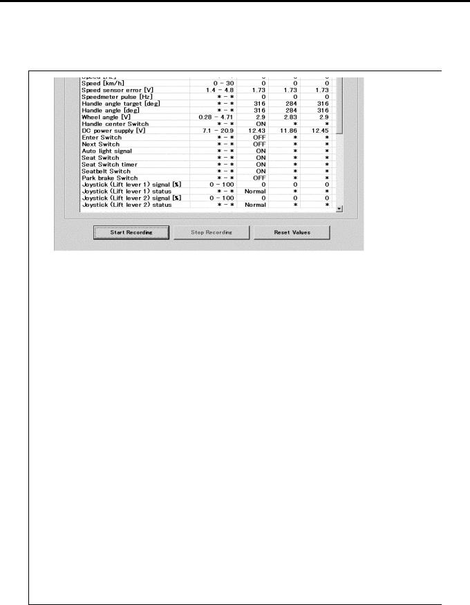
TABLE OF STANDARD TIGHTENING TORQUES
3.2 Input Monitor and Output Monitor
These screens indicate the input and output values of each controller.
3.2.1 VCM-3 input monitor and output monitor (VCM-3 → VCM-3)
(InputUnit)
212339
00-22

00
(OutputUnit) [ V]
(OutputUnit )
(OutputUnit)
212340
00-23

3.2.2 VCM-3OP input monitor and output monitor (VCM-3 → VCM-3OP)
212341
00-24
00
3.2.3 MP input monitor (VCM-3→ MP)
212342
00-25

3.2.4 ECU input monitor and output monitor (VCM-3 → ECU)
Accel pedal position (unfiltered)
Accel pedal position (filtered)
Reference injection quantity
212343
00-26

00
3.3 Fault Status
This screen indicates all error codes occurring.
OutputUnit Communication error
InputUnit Communication error
212344
00-27
 Loading...