


For Gulf Countries
2014 Model
Shop Manual
4D3 diesel engine
FOREWORD
This Shop Manual is published for the information and guidance of personnel responsible for maintenance of Mitsubishi Fuso CANTER series truck, and includes procedures for adjustment and maintenance services.
We earnestly look forward to seeing that this manual is made full use of in order to perform correct services with no wastage.
For more details, please consult your nearest authorized Mitsubishi Fuso dealer or distributors.
Kindly note that the specifications and maintenance service figures are subject to change without prior notice in line with improvement which will be effected from time to time in the future.
OCTOBER 2013
Applicable models (engine) 4D33
4D34T4
GROUP INDEX
GENERAL....................................
ENGINE .......................................
LUBRICATION.............................
FUEL AND ENGINE
CONTROL ...................................
COOLING ....................................
INTAKE AND EXHAUST .............
00
11
12
13
14
15
©2013 Mitsubishi Fuso Truck & Bus Corporation Printed in Japan
This Shop Manual contains the information classified into the following groups.
If any system or equipment has two or more variations with significantly different construction, the variations are handled as different groups. These groups are identified by different alphabets preceded by the same number.
1. ENGINE volume (Pub.No.00ELT0042)
Group No. |
Group subject |
|
|
00 |
GENERAL |
|
|
11 |
ENGINE |
|
|
12 |
LUBRICATION |
|
|
13 |
FUEL AND ENGINE CONTROL |
|
|
14 |
COOLING |
|
|
15 |
INTAKE AND EXHAUST |
|
|
2. CHASSIS Supplement volume (Pub.No.00ELT0043) |
|
|
|
Group No. |
Group subject |
|
|
00 |
GENERAL |
|
|
22 |
MANUAL TRANSMISSION |
|
|
34 |
REAR SUSPENSION |
|
|
35E |
ANTI-LOCK BRAKE SYSTEM (ABS) |
|
|
37B |
STEERING <POWER STEERING (Except FB70)> |
|
|
41 |
BUMPER, FRAME AND REAR BODY |
|
|
42 |
CAB MOUNTING AND TILT |
|
|
55 |
HEATER, AIR-CONDITIONER AND VENTILATION |
|
|
3. ELECTRICAL volume (Pub.No.00ELT0044) |
|
|
|
Group No. |
Group subject |
|
|
54 |
ELECTRICAL |
|
|

GROUP 00 GENERAL
VEHICLE MODEL CODING SYSTEM |
00-2 |
|
|
|
|||
EQUIPMENT TYPE CODES LIST ...................................................... |
00-3 |
|
|
POWER TRAIN TABLE ...................................................................... |
00-4 |
|
|
HOW TO READ THIS MANUAL ......................................................... |
00-6 |
|
|
CHASSIS NUMBER, VEHICLE IDENTIFICATION NUMBER, |
|
|
|
ENGINE NUMBER AND NAME PLATE ........................................... |
00-14 |
|
|
PRECAUTIONS FOR MAINTENANCE OPERATION |
00-16 |
|
|
1. |
General Precautions ................................................................... |
|
|
2. |
Handling of Battery..................................................................... |
00-19 |
|
3. |
Handling of Sensors, Relays and Electronic Control Units ......... |
00-19 |
|
4. |
Handling Precautions for Electric Circuits .................................. |
00-20 |
|
5. |
Service Precautions for Alternators............................................ |
00-23 |
|
6. |
Intermittent Faults ...................................................................... |
00-24 |
|
7. |
Precautions for Arc Welding....................................................... |
00-25 |
|
8. |
Precautions When Repainting .................................................... |
00-25 |
|
JACKING UP THE VEHICLE............................................................ |
00-26 |
|
|
DIAGNOSIS CODES |
00-28 |
|
|
1. |
Diagnosis Codes ........................................................................ |
|
|
2. |
Reading and Erasing the Diagnosis Code................................... |
00-29 |
|
TABLE OF STANDARD TIGHTENING TORQUES |
00-34 |
|
|
1. |
Tightening Torques..................................................................... |
|
|
2. |
Table of Standard Tightening Torque .......................................... |
00-34 |
|
00-1

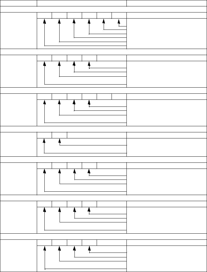
VEHICLE MODEL CODING SYSTEM
|
1 |
2 |
3 |
4 |
5 |
6 |
7 |
8 |
9 |
10 11 12 13 |
|
|
F E 7 3 C B |
|
|
|
|
|
|||||
|
|
|
|
|
|
|
|
|
|
|
|
1 |
Basic vehicle type |
|
|
|
|
|
|
|
F |
|
Cab-over engine truck |
|
|
|
|
|
|
|
|
|
|
|
|
2 |
Load capacity, drive system |
|
|
|
|
|
E |
|
2 ton class and over, 4 × 2 |
||
|
|
|
|
|
|
|
|
||||
|
|
|
|
|
G |
|
2 ton class and over, 4 × 4 |
||||
|
|
|
|
|
|
|
|
|
|
||
|
|
|
|
|
|
|
|
|
|
|
|
3 |
Cab type |
|
|
|
|
|
|
|
7 |
|
Standard-width cab |
|
|
|
|
|
|
|
|
|
|
||
|
|
|
|
|
|
|
8 |
|
Wide cab |
||
|
|
|
|
|
|
|
|
|
|
||
|
|
|
|
|
|
|
|
|
|
|
|
|
|
|
|
|
|
|
|
|
3 |
|
Rigid axle |
|
|
|
|
|
|
|
|
|
|
Light duty vehicle (Payload 1500 to 3000 kg) |
|
|
|
|
|
|
|
|
|
|
|
|
|
4 |
Vehicle variations, Suspension |
|
|
|
|
4 |
|
Rigid axle |
|||
|
|
|
|
|
Light duty vehicle (G.V.M 6000 to 6900 kg) |
||||||
|
|
|
|
|
|
|
|
|
|
|
|
|
|
|
|
|
|
|
|
|
5 |
|
Rigid axle |
|
|
|
|
|
|
|
|
|
|
Light duty vehicle (G.V.M. 7000 kg or more) |
|
|
|
|
|
|
|
|
|
|
|
|
|
5 |
Engine |
|
|
|
|
|
|
|
C |
|
4D33 |
|
|
|
|
|
|
|
|
|
|
||
|
|
|
|
|
|
|
P |
|
4D34T4 |
||
|
|
|
|
|
|
|
|
|
|
||
|
|
|
|
|
|
|
|
|
|
|
|
|
|
|
|
|
|
|
|
|
B |
|
2500 mm |
|
|
|
|
|
|
|
|
|
|
|
|
|
|
|
|
|
|
|
|
|
C |
|
2750 mm |
6 |
Wheelbase |
|
|
|
|
|
|
|
|
|
|
|
|
|
|
|
|
|
E |
|
3350 mm |
||
|
|
|
|
|
|
|
|
|
|
|
|
|
|
|
|
|
|
|
|
|
G |
|
3850 mm |
|
|
|
|
|
|
|
|
|
|
|
|
|
|
|
|
|
|
|
|
|
H |
|
4710 mm |
|
|
|
|
|
|
|
|
|
|
|
|
|
|
|
|
|
|
|
|
|
None |
|
Standard use |
|
|
|
|
|
|
|
|
|
|
||
7 |
Chassis arrangement for use |
|
|
|
|
|
D |
|
Dump use |
||
|
|
|
|
|
|
|
|
|
|
|
|
|
|
|
|
|
|
|
|
|
Z |
|
Wide frame |
|
|
|
|
|
|
|
|
|
|
|
|
8 |
Rear tire arrangement, Payload |
|
|
|
|
6 |
|
Rear double |
|||
|
|
|
|
|
Payload 3000 kg to 4000 kg |
||||||
|
|
|
|
|
|
|
|
|
|
|
|
|
|
|
|
|
|
|
|
|
S |
|
With turbocharger |
|
|
|
|
|
|
|
|
|
|
|
|
9 |
Vehicle specification |
|
|
|
|
|
|
W |
|
Crew cab |
|
|
|
|
|
|
|
|
|
|
|
|
|
|
|
|
|
|
|
|
|
|
None |
|
Standard |
|
|
|
|
|
|
|
|
|
|
|
|
10 |
Steering position |
|
|
|
|
|
|
|
L |
|
Left-hand drive vehicle |
|
|
|
|
|
|
|
|
|
|
|
|
11 to |
Export specification |
|
|
|
|
|
|
|
|
|
|
13 |
|
|
|
|
|
|
|
|
|
|
|
• The information from  to
to  is indicated on vehicles.
00-2
EQUIPMENT TYPE CODES LIST |
00 |
|
|
Component |
|
|
Name plate marking |
|
Code description |
|
Engine |
|
|
|
|
|
|
4D34T4 |
4 |
D |
3 |
4 |
T |
4 |
|
|
|
|
|
|
Power version number |
|
|
|
|
|
|
Turbocharged |
|
|
|
|
|
|
Order of development within same series |
|
|
|
|
|
|
Order of development among different series |
|
|
|
|
|
|
Diesel engine |
|
|
|
|
|
|
No. of cylinders (4) |
Clutch |
|
|
|
|
|
|
C4W30 |
C |
4 |
W |
30 |
|
|
|
|
|
|
|
|
Disc OD |
|
|
|
|
|
|
Facing material (W: Woven) |
|
|
|
|
|
|
Load carrying capacity of truck class (tonnage) |
|
|
|
|
|
|
on which the clutch is primarily used |
|
|
|
|
|
|
Initial letter of the clutch |
Transmission |
|
|
|
|
|
|
M035S5 |
M |
035 |
S |
5 |
|
|
|
|
|
|
|
|
Forward speeds |
|
|
|
|
|
|
Type of mesh (S: Synchromesh) |
|
|
|
|
|
|
Load carrying capacity of truck class (tonnage) |
|
|
|
|
|
|
on which the clutch is primarily used |
|
|
|
|
|
|
Initial letter of the transmission |
Propeller shaft |
|
|
|
|
|
|
P3 |
P |
3 |
|
|
|
|
|
|
|
|
|
|
Load carrying capacity of truck class (tonnage) |
|
|
|
|
|
|
on which the clutch is primarily used |
|
|
|
|
|
|
Initial letter of the propeller shaft |
Front axle |
|
|
|
|
|
|
F200T |
F |
200 |
T |
W |
|
|
|
|
|
|
|
|
Axle type |
|
|
|
|
|
|
Vehicle type (T: Truck) |
|
|
|
|
|
|
Load carrying capacity of truck class (tonnage) |
|
|
|
|
|
|
on which the clutch is primarily used |
|
|
|
|
|
|
Initial letter of the front axle |
Rear axle |
|
|
|
|
|
|
R035T |
R |
03 |
5 |
T |
|
|
|
|
|
|
|
|
Vehicle type (T: Truck) |
|
|
|
|
|
|
Order of development within same series |
|
|
|
|
|
|
Load carrying capacity of truck class (tonnage) |
|
|
|
|
|
|
on which the clutch is primarily used |
|
|
|
|
|
|
Initial letter of the rear axle |
Reduction and differential |
|
|
|
|
|
|
D035H |
D |
03 |
5 |
H |
|
|
|
|
|
|
|
|
Tooth profile (H: Hypoid gear) |
|
|
|
|
|
|
Order of development within same series |
|
|
|
|
|
|
Load carrying capacity of truck class (tonnage) |
|
|
|
|
|
|
on which the clutch is primarily used |
|
|
|
|
|
|
Initial letter of the reduction & differential |
00-3

POWER TRAIN TABLE
• FE
Vehicle model |
Engine |
Clutch |
Transmission |
Propeller |
Front axle |
Rear axle |
Reduction & |
|
shaft |
Differential |
|||||||
|
|
|
|
|
|
|||
|
|
|
|
|
|
|
|
|
FE73CB6LADG |
4D33 |
C4W30 |
M035S5 |
P3 |
F200T |
R033T |
D033H |
|
|
|
|
|
|
|
|
|
|
FE73CE6LADG |
4D33 |
C4W30 |
M035S5 |
P3 |
F200T |
R033T |
D033H |
|
|
|
|
|
|
|
|
|
|
FE84CCD6LGSG |
4D33 |
C4W30 |
M035S5 |
P3 |
F200T |
R033T |
D033H |
|
|
|
|
|
|
|
|
|
|
FE84CE6LADG |
4D33 |
C4W30 |
M035S5 |
P3 |
F200T |
R033T |
D033H |
|
|
|
|
|
|
|
|
|
|
FE84CE6WLGSG |
4D33 |
C4W30 |
M035S5 |
P3 |
F200T |
R033T |
D033H |
|
|
|
|
|
|
|
|
|
|
FE84CG6LADG |
4D33 |
C4W30 |
M035S5 |
P3 |
F200T |
R033T |
D033H |
|
|
|
|
|
|
|
|
|
|
FE85CC6LADG |
4D33 |
C4W30 |
M035S5 |
P3 |
F200T |
R035T |
D035H |
|
|
|
|
|
|
|
|
|
|
FE85CG6LADG |
4D33 |
C4W30 |
M035S5 |
P3 |
F200T |
R035T |
D035H |
|
|
|
|
|
|
|
|
|
|
FE85CHZLADG |
4D33 |
C4W30 |
M035S5 |
P3 |
F200T |
R040 |
D040H |
|
|
|
|
|
|
|
|
|
|
FE85PHZSLADG |
4D34T4 |
C4W30 |
M035S5 |
P3 |
F200T |
R040 |
D040H |
|
|
|
|
|
|
|
|
|
• FG
Vehicle model |
Engine |
Clutch |
Transmission |
Propeller |
Front axle |
Rear axle |
Reduction & |
|
shaft |
Differential |
|||||||
|
|
|
|
|
|
|||
|
|
|
|
|
|
|
|
|
FG83CE6LGSG |
4D33 |
C4W30 |
M035S5 |
Front: P2 |
F200TW |
R035T |
Front: D1H |
|
Rear: P3 |
Rear: D033H |
|||||||
|
|
|
|
|
|
|||
FG83CE6WLGSG |
4D33 |
C4W30 |
M035S5 |
Front: P2 |
F200TW |
R035T |
Front: D1H |
|
Rear: P3 |
Rear: D033H |
|||||||
|
|
|
|
|
|
00-4

00
M E M O
00-5

HOW TO READ THIS MANUAL
This manual consists of the following parts:
•Specifications
•Structure and Operation
•Troubleshooting
•Circuits
•Electrical Equipment Installation Positions
•Inspection of Electrical Equipment
•On-vehicle Inspection and Adjustment
•Service procedures
•Connector configuration chart
On-vehicle Inspection and Adjustment
•Procedures for inspection and adjustment of individual parts and assemblies as mounted on the vehicle are described including specific items to check and adjust. Specified or otherwise, inspection should be performed for looseness, play, backlash, crack, damage, etc.
Service procedures
•Procedures for servicing components and parts off the vehicle are described centering on key points in their removal, installation, disassembly, reassembly, inspection, etc.
Inspection
•Check items subject to “acceptable/unacceptable” judgement on the basis of service standards are all given.
•Some routine visual checks and cleaning of some reused parts are not described but must always be included in actual service work.
Caution
•This service manual contains important cautionary instructions and supplementary information under the following four headings which identify the nature of the instructions and information:
DANGER 
WARNING 

CAUTION 
NOTE
Terms and Units
Precautions that should be taken in handling potentially dangerous substances such as battery fluid and coolant additives.
Precautionary instructions, which, if not observed, could result in serious injury or death.
Precautionary instructions, which, if not observed, could result in damage to or destruction of equipment or parts.
Suggestions or supplementary information for more efficient use of equipment or better understanding.
•Front and rear
The forward running direction of the vehicle is referred to as the front and the reverse running direction is referred to as the rear.
•Left and right
Left hand side and right hand side, when facing the forward running direction of the vehicle, are respectively left and right.
Standard value
•Standard value dimensions in designs indicating: the design dimensions of individual parts, the standard clearance between two parts when assembled, and the standard value for an assembly part, as the case may be.
Limit
•When the value of a part exceeds this, it is no longer serviceable in respect of performance and strength and must be replaced or repaired.
00-6

00
Tightening torque
•Values are directly specified for out-of-standard tightening torques for bolts and nuts.
•Where there is no specified figure for tightening torque, follow the table covering standard tightening torques. (Values for standard tightening torques are based on thread size and material.)
•When the item is to be tightened in a wet state, “wet” is indicated. Where there is no indication, read it as dry.
Units
• Tightening torques and other parameters are given in SI* units with metric units added in brackets { }.
*SI: Le Système International d’Unités
Example: 390 N·m {40 kgf·m}
Metric unit
SI unit
|
Unit |
SI unit {metric unit} |
Conversion factor |
|
|
|
|
Force |
N {kgf} |
9.80665 N {1 kgf} |
|
|
|
|
|
Moment of force |
N·m {kgf·m} |
9.80665 N·m {1 kgf·m} |
|
|
|
|
|
|
Positive pressure |
kPa {kgf/cm2} |
98.0665 kPa {1 kgf/cm2} |
Pressure |
Vacuum pressure |
kPa {mmHg} |
0.133322 kPa {1 mmHg} |
|
Pa {mmH2O} |
9.80665 Pa {1 mmH2O} |
|
|
|
||
Volume |
dm3 {L} |
1 dm3 {1 L} |
|
Heat quantity |
J {kcal} |
4186.05 J {1 kcal} |
|
|
|
|
|
Heat flow |
W {kcal/h} |
1.16279 W {1 kcal/h} |
|
|
|
|
|
Power |
kW {PS} |
0.7355 kW {1 PS} |
|
|
|
|
|
00-7
HOW TO READ THIS MANUAL
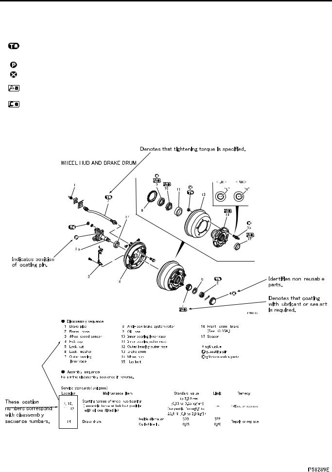
Illustrated Parts Breakdown and Service Procedures
|
Symbol |
|
Denotation |
|
|
|
|
|
|
|
Application |
|
|
|
|
|
Remarks |
||||||||||||||||||||||||||
|
|
|
|
|
|
|
|
|
|
|
|
|
|
|
|
|
|
|
|
|
|
|
|
|
|
|
|
|
|
|
|
|
|
|
|
|
|
|
|
|
|
|
|
|
|
|
|
|
|
|
|
|
|
|
|
|
Parts not tightened to standard torques |
Specified values shown in table |
|||||||||||||||||||||||||||||
|
|
|
|
|
|
|
|
|
|
|
|
|
See Table of Standard Tightening Torques for |
||||||||||||||||||||||||||||||
|
|
|
|
Tightening torque |
|
(standard torques specified where neces- |
|||||||||||||||||||||||||||||||||||||
|
|
|
|
|
parts for which no tightening torques are speci- |
||||||||||||||||||||||||||||||||||||||
|
|
|
|
|
|
|
|
|
|
|
|
|
sary for servicing) |
||||||||||||||||||||||||||||||
|
|
|
|
|
|
|
|
|
|
|
|
|
fied. |
||||||||||||||||||||||||||||||
|
|
|
|
|
|
|
|
|
|
|
|
|
|
|
|
|
|
|
|
|
|
|
|
|
|
|
|
|
|
|
|||||||||||||
|
|
|
|
|
|
|
|
|
|
|
|
|
|
|
|
|
|
|
|
|
|
|
|
|
|
|
|
|
|
|
|
|
|
|
|
|
|
|
|
|
|
|
|
|
|
|
|
Locating pin |
|
Parts to be positioned for installation |
|
|
|
|
|
|
|
|
|
|
|
|
|
||||||||||||||||||||||||
|
|
|
|
|
|
|
|
|
|
|
|
|
|
|
|
|
|
|
|
|
|
|
|
|
|
|
|
|
|
|
|
|
|
|
|
|
|
|
|
|
|
|
|
|
|
|
|
Non-reusable parts |
|
Parts not to be reused |
|
|
|
|
|
|
|
|
|
|
|
|
|
||||||||||||||||||||||||
|
|
|
|
|
|
|
|
|
|
|
|
|
|
|
|
|
|
|
|
|
|
|
|
|
|
|
|
|
|
|
|
|
|
|
|
|
|
|
|
|
|
|
|
|
|
|
|
Lubricant and/or |
|
Parts to be coated with lubricant or sealant |
Necessary lubricant and/or sealant, quantity re- |
||||||||||||||||||||||||||||||||||||
|
|
|
|
sealant |
|
for assembly or installation |
quired, etc. are specified in table. |
||||||||||||||||||||||||||||||||||||
|
|
|
|
Special tool |
|
Parts for which special tools are required for |
Tool name/shape and part number are shown in |
||||||||||||||||||||||||||||||||||||
|
|
|
|
|
service operation |
table. |
|||||||||||||||||||||||||||||||||||||
|
|
|
|
|
|
|
|
|
|
|
|
|
|||||||||||||||||||||||||||||||
|
*a |
Associated part |
|
Parts associated with those removed/disas- |
|
|
|
|
|
|
|
|
|
|
|
|
|
||||||||||||||||||||||||||
|
|
sembled for servicing |
|
|
|
|
|
|
|
|
|
|
|
|
|
||||||||||||||||||||||||||||
|
|
|
|
|
|
|
|
|
|
|
|
|
|
|
|
|
|
|
|
|
|
|
|
|
|
||||||||||||||||||
|
|
|
|
|
|
|
|
|
|
|
|
|
|
|
|
|
|
|
|
|
|
|
|
|
|
|
|
|
|
|
|
|
|
|
|
|
|
|
|
|
|
|
|
|
|
|
|
|
|
|
|
|
|
|
|
|
|
|
|
|
|
|
|
|
|
|
|
|
|
|
|
|
|
|
|
|
|
|
|
|
|
|
|
|
|
|
|
|
|
|
|
|
|
|
|
|
|
|
|
|
|
|
|
|
|
|
|
|
|
|
|
|
|
|
|
|
|
|
|
|
|
|
|
|
|
|
|
|
|
|
|
|
|
|
|
|
|
|
|
|
|
|
|
|
|
|
|
|
|
|
|
|
|
|
|
|
|
|
|
|
|
|
|
|
|
|
|
|
|
|
|
|
|
|
|
|
|
|
|
|
|
|
|
|
|
|
|
|
|
|
|
|
|
|
|
|
|
|
|
|
|
|
|
|
|
|
|
|
|
|
|
|
|
|
|
|
|
|
|
|
|
|
|
|
|
|
|
|
|
|
|
|
|
|
|
|
|
|
|
|
|
|
|
|
|
|
|
|
|
|
|
|
|
|
|
|
|
|
|
|
|
|
|
|
|
|
|
|
|
|
|
|
|
|
|
|
|
|
|
|
|
|
|
|
|
|
|
|
|
|
|
|
|
|
|
|
|
|
|
|
|
|
|
|
|
|
|
|
|
|
|
|
|
|
|
|
|
|
|
|
|
|
|
|
|
|
|
|
|
|
|
|
|
|
|
|
|
|
|
|
|
|
|
|
|
|
|
|
|
|
|
|
|
|
|
|
|
|
|
|
|
|
|
|
|
|
|
|
|
|
|
|
|
|
|
|
|
|
|
|
|
|
|
|
|
|
|
|
|
|
|
|
|
|
|
|
|
|
|
|
|
|
|
|
|
|
|
|
|
|
|
|
|
|
|
|
|
|
|
|
|
|
|
|
|
|
|
|
|
|
|
|
|
|
|
|
|
|
|
|
|
|
|
|
|
|
|
|
|
|
|
|
|
|
|
|
|
|
|
|
|
|
|
|
|
|
|
|
|
|
|
|
|
|
|
|
|
|
|
|
|
|
|
|
|
|
|
|
|
|
|
|
|
|
|
|
|
|
|
|
|
|
|
|
|
|
|
|
|
|
|
|
|
|
|
|
|
|
|
|
|
|
|
|
|
|
|
|
|
|
|
|
|
|
|
|
|
|
|
|
|
|
|
|
|
|
|
|
|
|
|
|
|
|
|
|
|
|
|
|
|
|
|
|
|
|
|
|
|
|
|
|
|
|
|
|
|
|
|
|
|
|
|
|
|
|
|
|
|
|
|
|
|
|
|
|
|
|
|
|
|
|
|
|
|
|
|
|
|
|
|
|
|
|
|
|
|
|
|
|
|
|
|
|
|
|
|
|
|
|
|
|
|
|
|
|
|
|
|
|
|
|
|
|
|
|
|
|
|
|
|
|
|
|
|
|
|
|
|
|
|
|
|
|
|
|
|
|
|
|
|
|
|
|
|
|
|
|
|
|
|
|
|
|
|
|
|
|
|
|
|
|
|
|
|
|
|
|
|
|
|
|
|
|
|
|
|
|
|
|
|
|
|
|
|
|
|
|
|
|
|
|
|
|
|
|
|
|
|
|
|
|
|
|
|
|
|
|
|
|
|
|
|
|
|
|
|
|
|
|
|
|
|
|
|
|
|
|
|
|
|
|
|
|
|
|
|
|
|
|
|
|
|
|
|
|
|
|
|
|
|
|
|
|
|
|
|
|
|
|
|
|
|
|
|
|
|
|
|
|
|
|
|
|
|
|
|
|
|
|
|
|
|
|
|
|
|
|
|
|
|
|
|
|
|
|
|
|
|
|
|
|
|
|
|
|
|
|
|
|
|
|
|
|
|
|
|
|
|
|
|
|
|
|
|
|
|
|
|
|
|
|
|
|
|
|
|
|
|
|
|
|
|
|
|
|
|
|
|
|
|
|
|
|
|
|
|
|
|
|
|
|
|
|
|
|
|
|
|
|
|
|
|
|
|
|
|
|
|
|
|
|
|
|
|
|
|
|
|
|
|
|
|
|
|
|
|
|
|
|
|
|
|
|
|
|
|
|
|
|
|
|
|
|
|
|
|
|
|
|
|
|
|
|
|
|
|
|
|
|
|
|
|
|
|
|
|
|
|
|
|
|
|
|
|
|
|
|
|
|
|
|
|
|
|
|
|
|
|
|
|
|
|
|
|
|
|
|
|
|
|
|
|
|
|
|
|
|
|
|
|
|
|
|
|
|
|
|
|
|
|
|
|
|
|
|
|
|
|
|
|
|
|
|
|
|
|
|
|
|
|
|
|
|
|
|
|
|
|
|
|
|
|
|
|
|
|
|
|
|
|
|
|
|
|
|
|
|
|
|
|
|
|
|
|
|
|
|
|
|
|
|
|
|
|
|
|
|
|
|
|
|
|
|
|
|
|
|
|
|
|
|
|
|
|
|
|
|
|
|
|
|
|
|
|
|
|
|
|
|
|
|
|
|
|
|
|
|
|
|
|
|
|
|
|
|
|
|
|
|
|
|
|
|
|
|
|
|
|
|
|
|
|
|
|
|
|
|
|
|
|
|
|
|
|
|
|
|
|
|
|
|
|
|
|
|
|
|
|
|
|
|
|
|
|
|
|
|
|
|
|
|
|
|
|
|
|
|
|
|
|
|
|
|
|
|
|
|
|
|
|
|
|
|
|
|
|
|
|
|
|
|
|
|
|
|
|
|
|
|
|
|
|
|
|
|
|
|
|
|
|
|
|
|
|
|
|
|
|
|
|
|
|
|
|
|
|
|
|
|
|
|
|
|
|
|
|
|
|
|
|
|
|
|
|
|
|
|
|
|
|
|
|
|
|
|
|
|
|
|
|
|
|
|
|
|
|
|
|
|
|
|
|
|
|
|
|
|
|
|
|
|
|
|
|
|
|
|
|
|
|
|
|
|
|
|
|
|
|
|
|
|
|
|
|
|
|
|
|
|
|
|
|
|
|
|
|
|
|
|
|
|
|
|
|
|
|
|
|
|
|
|
|
|
|
|
|
|
|
|
|
|
|
|
|
|
|
|
|
|
|
|
|
|
|
|
|
|
|
|
|
|
|
|
|
|
|
|
|
|
|
|
|
|
|
|
|
|
|
|
|
|
|
|
|
|
|
|
|
|
|
|
|
|
|
|
|
|
|
|
|
|
|
|
|
|
|
|
|
|
|
|
|
|
|
|
|
|
|
|
|
|
|
|
|
|
|
|
|
|
|
|
|
|
|
|
|
|
|
|
|
|
|
|
|
|
|
|
|
|
|
|
|
|
|
|
|
|
|
|
|
|
|
|
|
|
|
|
|
|
|
|
|
|
|
|
|
|
|
|
|
|
|
|
|
|
|
|
|
|
|
|
|
|
|
|
|
|
|
|
|
|
|
|
|
|
|
|
|
|
|
|
|
|
|
|
|
|
|
|
|
|
|
|
|
|
|
|
|
|
|
|
|
|
|
|
|
|
|
|
|
|
|
|
|
|
|
|
|
|
|
|
|
|
|
|
|
|
|
|
|
|
|
|
|
|
|
|
|
|
|
|
|
|
|
|
|
|
|
|
|
|
|
|
|
|
|
|
|
|
|
|
|
|
|
|
|
|
|
|
|
|
|
|
|
|
|
|
|
|
|
|
|
|
|
|
|
|
|
|
|
|
|
|
|
|
|
|
|
|
|
|
|
|
|
|
|
|
|
|
|
|
|
|
|
|
|
|
|
|
|
|
|
|
|
|
|
|
|
|
|
|
|
|
|
|
|
|
|
|
|
|
|
|
|
|
|
|
|
|
|
|
|
|
|
|
|
|
|
|
|
|
|
|
|
|
|
|
|
|
|
|
|
|
|
|
|
|
|
|
|
|
|
|
|
|
|
|
|
|
|
|
|
|
|
|
|
|
|
|
|
|
|
|
|
|
|
|
|
|
|
|
|
|
|
|
|
|
|
|
|
|
|
|
|
|
|
|
|
|
|
|
|
|
|
|
|
|
|
|
|
|
|
|
|
|
|
|
|
|
|
|
|
|
|
|
|
|
|
|
|
|
|
|
|
|
|
|
|
|
|
|
|
|
|
|
|
|
|
|
|
|
|
|
|
|
|
00-8
00
00-9

HOW TO READ THIS MANUAL
How to Read Circuits (Electrical)
00-10 |
00
1.1 Index number: 100 to 999
• Index numbers are used as reference numbers for electrical circuits. Each electrical circuit has been assigned its own index number.
1.2 Key number: A01 to Z99
• Key numbers indicate electrical equipment installation locations. The installation location of an electrical equipment can be easily found using its key number shown in a circuit diagram.
All of the electrical equipment installation locations are listed in Gr54-10.
1.3 Part name
1.4 Connector type (type indication)
• A list of the connectors used is included in Gr54-14.
1.5Connector terminal number
1.6Major harness division
• Major harness divisions are shown.
1.7 Wiring variations between different specifications
• Variations in wiring/circuit between different vehicle specifications are clearly indicated as shown.
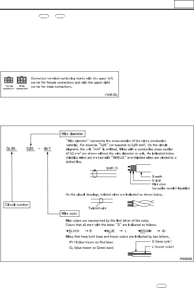
1.8 Circuit number, wire diameter, wire color
1.9 Code number: #001 to #999
•Code numbers are reference numbers to find individual electrical equipment inspection procedures. The inspection procedure for an electrical equipment can be found using its code number shown in a circuit diagram.
1.10Grounding point: [1] to [99]
•Locations where wires are grounded to the vehicle. All of the grounding points are listed in  130 .
130 .
1.11Harness connection
•The arrow in the wiring diagram indicates where harnesses are connected, and NOT the flow of electricity.
00-11

HOW TO READ THIS MANUAL
Wire color
Wire color |
|
|
|
|
|
Base color + tracer |
|
|
|
|
|
||
|
|
|
|
|
|
|
|
|
|
|
|
|
|
|
|
BW |
Black/ |
BY |
Black/ |
BR |
Black/red |
BG |
Black/ |
BL |
Black/ |
BO |
Black/ |
B |
Black |
|
white |
|
yellow |
|
|
|
green |
|
blue |
|
orange |
BP |
Black/ |
BV |
Black/ |
B Br |
Black/ |
|
|
|
|
|
|
||
|
|
|
|
|
|
|
|
||||||
|
|
|
pink |
|
violet |
|
brown |
|
|
|
|
|
|
|
|
BrW |
Brown/ |
BrB |
Brown/ |
BrY |
Brown/ |
BrR |
Brown/ |
BrG |
Brown/ |
BrL |
Brown/ |
Br |
Brown |
white |
black |
yellow |
red |
green |
blue |
||||||
BrGr |
Brown/ |
BrV |
Brown/ |
|
|
|
|
|
|
|
|
||
|
|
|
|
|
|
|
|
|
|
||||
|
|
|
gray |
|
Violet |
|
|
|
|
|
|
|
|
|
|
GW |
Green/ |
GR |
Green/ |
GY |
Green/ |
GB |
Green/ |
GL |
Green/ |
GO |
Green/ |
G |
Green |
|
white |
|
red |
|
yellow |
|
black |
|
blue |
|
orange |
GGr |
Green/ |
GBr |
Green/ |
GV |
Green/ |
|
|
|
|
|
|
||
|
|
|
|
|
|
|
|
||||||
|
|
gray |
brown |
violet |
|
|
|
|
|
|
|||
|
|
|
|
|
|
|
|
|
|
|
|
|
|
|
|
GrL, |
Gray/ |
GrR, |
Gray/ |
GrB, |
Gray/ |
GrG, |
Gray/ |
GrW, |
Gray/ |
GrY |
Gray/ |
Gr, |
Gray |
GyL |
blue |
GyR |
red |
GyB |
black |
GyG |
green |
GyW |
white |
yellow |
|
Gy |
GrG |
Gray/ |
GrBr |
Gray/ |
|
|
|
|
|
|
|
|
|
|
|
|
|
|
|
|
|
|
|||||
|
|
|
|
|
|
|
|
|
|
||||
|
|
|
green |
|
brown |
|
|
|
|
|
|
|
|
|
|
LW |
Blue/ |
LR |
Blue/red |
LY |
Blue/ |
LB |
Blue/ |
LO |
Blue/ |
LG |
Blue/ |
L |
Blue |
white |
yellow |
black |
orange |
green |
|||||||
LGr |
Blue/gray |
LBr |
Blue/ |
|
|
|
|
|
|
|
|
||
|
|
|
|
|
|
|
|
|
|
||||
|
|
brown |
|
|
|
|
|
|
|
|
|||
|
|
|
|
|
|
|
|
|
|
|
|
|
|
|
|
|
|
|
|
|
|
|
|
|
|
|
|
|
Light |
|
Light |
|
Light |
|
Light |
|
Light |
|
|
|
|
Lg |
LgR |
green/ |
LgY |
green/ |
LgB |
green/ |
LgW |
green/ |
|
|
|
|
|
green |
|
|
|
|
|||||||||
|
|
|
red |
|
yellow |
|
black |
|
white |
|
|
|
|
O |
Orange |
OL |
Orange/ |
OB |
Orange/ |
OG |
Orange/ |
|
|
|
|
|
|
blue |
black |
green |
|
|
|
|
|
|
|||||
P |
Pink |
PB |
Pink/ |
PG |
Pink/ |
PL |
Pink/ |
PW |
Pink/ |
PGr |
Pink/gray |
PV |
Pink/ |
|
|
|
black |
|
green |
|
blue |
|
white |
|
|
|
violet |
Pu |
Purple |
|
|
|
|
|
|
|
|
|
|
|
|
|
|
|
|
|
|
|
|
|
|
|
|
|
|
|
|
RW |
Red/ |
RB |
Red/ |
RY |
Red/ |
RG |
Red/ |
RL |
Red/blue |
RO |
Red/ |
R |
Red |
white |
black |
yellow |
green |
orange |
|||||||
RBr |
Red/ |
Rgr |
Red/ |
|
|
|
|
|
|
|
|
||
|
|
|
|
|
|
|
|
|
|
||||
|
|
brown |
Gray |
|
|
|
|
|
|
|
|
||
|
|
|
|
|
|
|
|
|
|
|
|
|
|
Sb |
Sky blue |
|
|
|
|
|
|
|
|
|
|
|
|
|
|
|
|
|
|
|
|
|
|
|
|
|
|
V |
Violet |
VY |
Violet/yel- |
VW |
Violet/ |
VR |
Violet/red |
VG |
Violet/ |
VGr |
Violet/ |
VB |
Violet/ |
|
|
|
low |
|
white |
|
|
|
green |
|
gray |
|
black |
|
|
WR |
White/ |
WB |
White/ |
WL |
White/ |
WG |
White/ |
WO |
White/ |
WV |
White/ |
W |
White |
red |
black |
blue |
green |
orange |
violet |
||||||
WBr |
White/ |
WY |
White/ |
|
|
|
|
|
|
|
|
||
|
|
|
|
|
|
|
|
|
|
||||
|
|
brown |
yellow |
|
|
|
|
|
|
|
|
||
|
|
|
|
|
|
|
|
|
|
|
|
|
|
|
|
YR |
Yellow/ |
YB |
Yellow/ |
YG |
Yellow/ |
YL |
Yellow/ |
YW |
Yellow/ |
YO |
Yellow/ |
Y |
Yellow |
|
red |
|
black |
|
green |
|
blue |
|
white |
|
orange |
YP |
Yellow/ |
YV |
Yellow/ |
YGr |
Yellow/ |
YBr |
Yellow/ |
|
|
|
|
||
|
|
|
|
|
|
||||||||
|
|
pink |
violet |
gray |
brown |
|
|
|
|
||||
|
|
|
|
|
|
|
|
|
|
|
|
|
|
00-12

00
M E M O
00-13

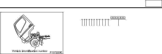
CHASSIS NUMBER, VEHICLE IDENTIFICATION NUMBER, ENGINE NUMBER AND NAME PLATE
•Serial chassis and engine numbers are assigned to the vehicles and engines in manufacturing sequence. Every vehicle and engine has its own number. These numbers are required for registration and related inspection of the vehicle.
Chassis number
Engine number
Name plate
• Name plate contains the following information.
•Month and year of manufacture
•Gross vehicle mass
•Front permissible load
•Rear permissible load
•Chassis number or vehicle identification number
00-14
00
Vehicle identification number (V.I.N.)
Example: J L 6 B 5 E 1 K 
 E K
E K
|
(1) (2) (3) (4) (5) (6) (7)(8) (9) (10) (11) |
|
(12) |
|
(1) |
Country |
J : Japan |
||
(2) |
Make |
L : Mitsubishi Fuso Truck & Bus |
||
(3) |
Vehicle type |
6 |
: Incomplete vehicle |
|
|
|
7 |
: Truck |
|
(4) |
G.V.W./Brake system |
B : |
3500 kg < G.V.W. ≤ 1200 kg/ |
|
|
|
|
|
Hydraulic |
(5) |
Model |
5 |
: FE73C |
|
|
|
6 |
: FE84C |
|
|
|
7 |
: FE85C |
|
|
|
8 |
: FG83C |
|
|
|
9 |
: FE85P-Z |
|
(6) |
Series (wheelbase) |
1 |
: |
2.3 to 2.59 m |
|
|
C : |
2.6 to 2.89 m |
|
|
|
D : |
2.9 to 3.19 m |
|
|
|
E : |
3.2 to 3.49 m |
|
|
|
G: |
3.8 to 4.09 m |
|
|
|
H : |
4.1 to 4.39 m |
|
(7) |
Chassis cab type |
1 |
: |
Cargo |
|
|
2 |
: |
Dump |
|
|
5 |
: |
Others |
(8) |
Engine |
J : |
3.097 L |
|
|
|
|
|
Diesel engine (4D34T4) |
|
|
P : |
4.214 L |
|
(9) |
Check digit |
|
|
Diesel engine (4D33) |
|
|
|
||
(10) Model year |
E : |
2014 |
||
|
|
F : |
2015 |
|
|
|
G: |
2016 |
|
|
|
H : |
2017 |
|
(11) Plant |
K : Kawasaki |
|||
(12) Serial No. |
|
|
|
|
00-15
PRECAUTIONS FOR MAINTENANCE OPERATION
1. General Precautions
•Before performing service operations, inquire into the customer’s complaints and ascertain the condition by checking the total distance traveled, the conditions under which the vehicle is operated, and other relevant factors on the vehicle. And note the necessary information. This information will help you to service the vehicle efficiently.
•Check the location of the fault, and identify its cause. Based on your findings, determine whether parts must be removed or disassembled. Then, follow the service procedure given in this manual.
•Perform service operations on a level surface. Before starting, take the following preparatory steps:
•To prevent soiling and damage, place covers over the seats, trim and floor in the cab and over the paintwork of the body.
• Prepare all the general and special tools necessary for the job.
WARNING 
•Special tools must be used wherever specified in this manual. Do not attempt to use other tools since they could cause injuries and/or vehicle damage.
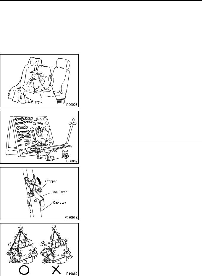
•After manually tilting the cab, be sure to engage the stopper with the lock lever to secure the cab stay in a rigid state.
•Take extreme care when removing/installing heavy items such as engine, transmission and axle. When lifting heavy items using
a cable etc., observe the following precautions.
• Identify the weight of the item being lifted. Use the cable that is strong enough to support the weight.
00-16

00
•If lifting eyes are not provided on the item being lifted, tie a cable around the item taking into account the item’s center of gravity.
•Do not allow anyone to pass or stay under a lifted item which may possibly fall.
•Never work in shoes that have oily soles.
When working with a partner or in a group, use pre-arranged signals and pay constant attention to safety. Be careful not to touch switches and levers unintentionally.
•Inspect for oil leakage etc. before washing the vehicle. If the order is reversed, any oil leakage or fault that may exist could go unnoticed during inspection.
• Prepare replacement parts ready for installation.
00-17
PRECAUTIONS FOR MAINTENANCE OPERATION
•Oil seals, packings, O-rings and other rubber parts, gaskets, and split pins must be replaced with new ones after removal. Use only genuine MITSUBISHI replacement parts.
•When disassembling parts, visually check them for wear, cracks, damage, deformation, deterioration, rust, corrosion, defective rotation, fatigue, clogging and any other possible defect.
•To facilitate correct reassembly of parts, make alignment marks on them before disassembly and arrange disassembled parts neatly. Make punch marks and other alignment marks where they will not detract from parts’ functionality and appearance.
•After removing parts from the vehicle, cover the area to keep it free of dust.
CAUTION 
•Be careful not to mix up identical parts, similar parts and parts that have left/right alignments.
•Keep new replacement parts and original (removed) parts separately.
•Apply the specified oil or grease to U-seals, oil seals, dust seals and bearings before reassembly.
•Always use the specified oils and greases when performing inspection or replacement. Immediately wipe away any excess oil or grease with a rag.
•Wear safety goggles when using a grinder or welder. Wear gloves when necessary, and watch out for sharp edges and other items that might wound your hands.
00-18
00
2. Handling of Battery
2.1 Handling of battery cable
•Before working on the electrical system, disconnect the (–) battery cable to prevent short circuits.
CAUTION 
•Make sure that the starter switch and lighting switches are OFF before disconnecting or connecting battery cable. (Semiconductor components may otherwise be damaged.)
•Disconnect the (–) battery cable, then insulate the (–) terminal of the battery and (–) battery cable with insulating tape
or the like.
•If the (–) battery cable is not disconnected, battery voltage will remain constantly applied to the B terminal, inviting danger of electric shock.
3.Handling of Sensors, Relays and Electronic Control Units
•Carefully handle sensors relays, and other items that are sensitive to shock and heat. Do not remove or paint the cover of any control unit.
•When separating connectors, grasp the connectors themselves rather than the harnesses.
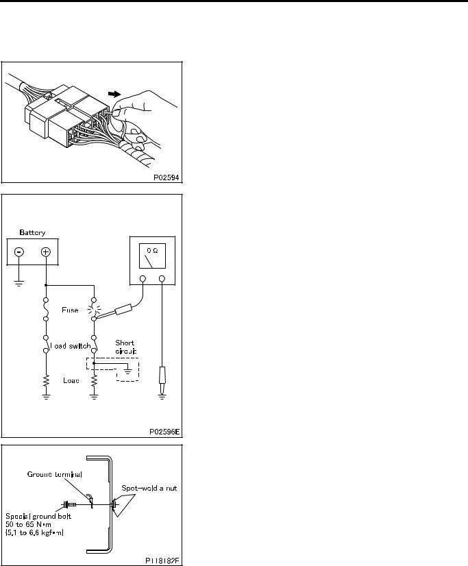
• To separate locking connectors, first push them in the direction of the arrows. To reconnect locking connectors, push them together until they click.
•Before washing the vehicle, cover electrical parts to keep them dry. (Use plastic sheets or equivalent.) Keep water away from harness connectors and sensors and immediately wipe off any water that gets on them.
00-19
PRECAUTIONS FOR MAINTENANCE OPERATION
• When applying a voltage to a part for inspection purposes, check that the (+) and (–) cables are connected properly then gradually increase the voltage from zero. Do not exceed the specified voltage.
Remember that control units and sensors do not necessarily operate on the battery voltage.
4. Handling Precautions for Electric Circuits
CAUTION 
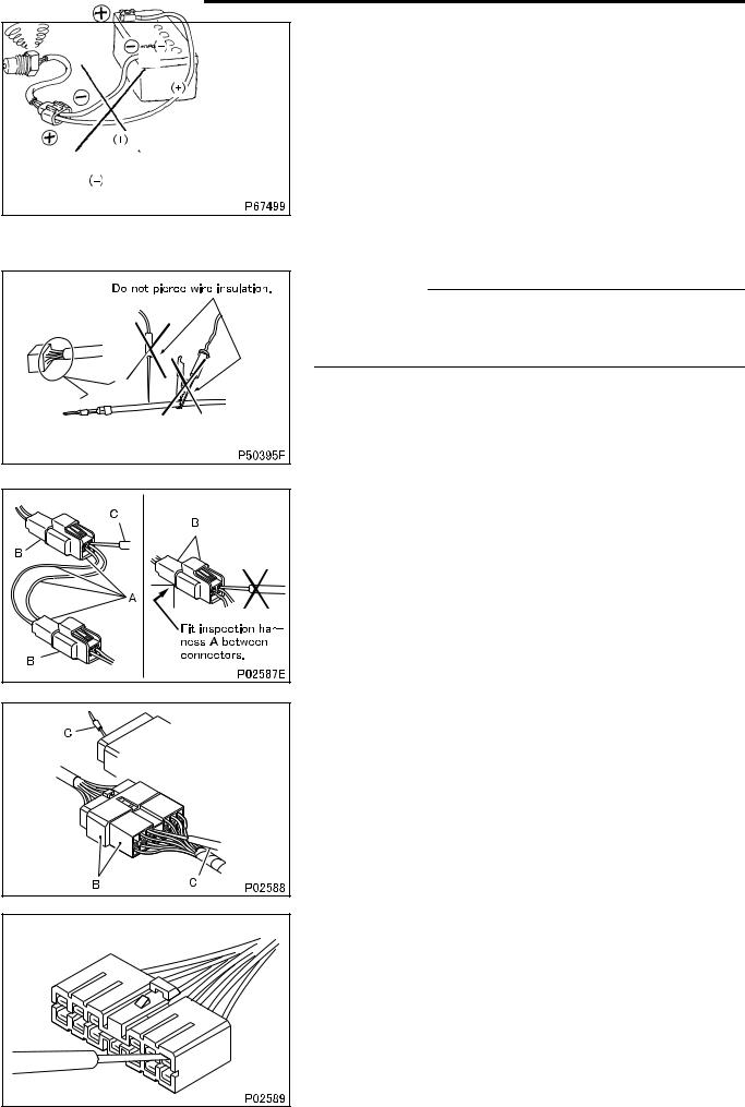
•Do not pierce wire insulation with test probes or alligator clips when performing electrical inspections. Doing so can,
particularly with the chassis harness, hasten corrosion.
4.1 Inspection of harnesses
(1) Inspections with connectors fitted together
(1.1) Waterproof connectors
• Connect an inspection harness and connector A between the connectors B of the circuit to be inspected. Perform the inspection by applying a test probe C to the connectors of the inspection harness. Do not insert the test probe C into the wire-entry sides of the waterproof connectors since this would damage their waterproof seals and lead to rust.
(1.2) Non-waterproof connectors
• Perform the inspection by inserting a test probe C into the wireentry sides of the connectors. An extra-narrow probe is required for control unit connectors, which are smaller than other types of connector. Do not force a regular-size probe into control unit connectors since this would cause damage.
00-20 |
(2) Inspections with connectors separated
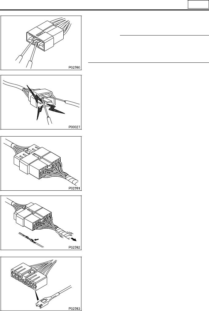
(2.1) Inspections on female terminals
•Perform the inspection by carefully inserting a test probe into the terminals. Do not force the test probe into the terminals since this could deform them and cause poor connections.
00
(2.2) Inspections on male terminals
• Perform the inspection by applying test probes directly to the pins.
.
CAUTION 
•Be careful not to short-circuit pins together with the test probes. With control unit connectors, short-circuiting of pins can cause damage to the control unit’s internal circuitry.
•When using a multimeter to check continuity, do not allow the test probes to touch the wrong terminals.
4.2 Inspection of connectors
(1) Visual inspection
• Check that the connectors are fitted together securely.
•Check whether wires have been separated from their terminals due to pulling of the harness.
• Check that male and female terminals fit together tightly.
00-21
PRECAUTIONS FOR MAINTENANCE OPERATION
•Check for defective connections caused by loose terminals, by rust on terminals, or by contamination of terminals by foreign substances.
(2) Checking for loose terminals
•If connector terminal retainers become damaged, male and female terminals may not mate with each other when the connector bodies are fitted together. To check for such terminals, gently pull each wire and see whether any terminals slip out of their connector housings.
4.3 Inspections when a fuse blows
•Remove the fuse, then measure the resistance between ground and the fuse’s load side.
Next, close the switch of each circuit connected to the fuse. If the resistance measurement between any switch and ground is zero, there is a short circuit between the switch and the load. If the resistance measurement is not zero, the circuit is not currently short-circuited; the fuse probably blew due to a momentary short circuit.
•The main causes of short circuits are as follows:
•Harnesses trapped between chassis parts
•Harness insulation damage due to friction or heat
•Moisture in connectors or circuitry
•Human error (accidental short-circuiting of components)
4.4 Inspection of chassis ground
•A special ground bolt is used to tighten a ground terminal. When servicing the ground point, be sure to follow the procedures described below:
•When reinstalling the ground bolt
Tighten the ground bolt to the specified torque.
•When relocating the ground point
A special ground bolt must be used. Spot-weld a nut to a frame and tighten the ground bolt to the specified torque. Be sure to apply touch-up paint to the welded point.
00-22
00
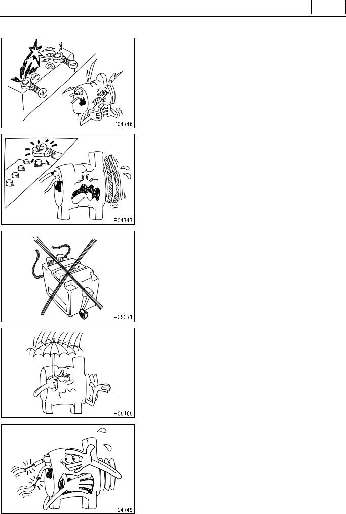
5.Service Precautions for Alternators
•When servicing alternators, observe the following precautions:
•Never reverse the polarity of battery connections.
If the polarity of the battery connections were to be reversed,
a large current would flow from the battery to the alternator, damaging the diodes and regulator.
•Never disconnect the battery cables with the engine running. Disconnection of the battery cables during engine operation would cause a surge voltage, leading to deterioration of the diodes and regulator.
•Never perform inspections using a high-voltage multimeter.
The use of a high-voltage multimeter could damage the diodes and regulator.
•Keep alternators dry.
Water on alternators can cause internal short circuits and damage.
•Never operate an alternator with the B and L terminals short-cir- cuited. Operation with the B and L terminals connected together would damage the diode trio.
00-23
PRECAUTIONS FOR MAINTENANCE OPERATION
6. Intermittent Faults
•Disconnect the battery cables before quick-charging the battery with a quick charger.
Unless the battery cables are disconnected, quick-charging can damage the diodes and regulator.
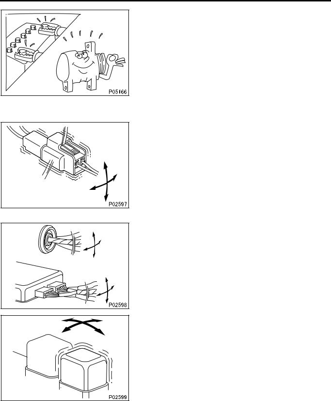
•An intermittent fault typically occurs only under certain operating conditions. Once these conditions have been identified, the cause of the intermittent fault can be ascertained easily. First, ask the customer about the vehicle operating conditions and weather conditions under which the fault occurs. Also ask about the frequency with which the fault occurs and about the fault symptoms. Then, reproduce the fault based on this information. In accordance with the conditions under which the fault occurs, determine whether the fault is caused by vibration, heat or other factors. if vibration is a possible factor, see if the fault can be reproduced by performing the following checks on individual connectors and other parts:
•Gently move connectors up and down and to left and right.
•Gently move wiring harnesses up and down and to left and right.
•Gently wiggle sensors and other devices by hand.
•Gently wiggle wiring harnesses on suspension systems and other moving parts.
•Connectors and other parts to be checked are those included or given as likely fault locations in inspection procedures corresponding to diagnosis codes and/or fault symptoms.
00-24
00
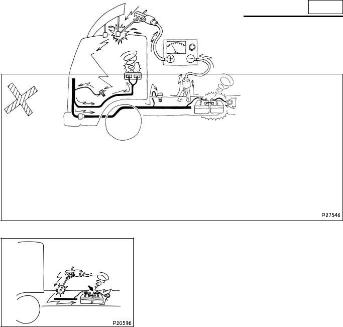
7. Precautions for Arc Welding
•When arc welding is performed, current from the welder flows to ground via the vehicle’s metal parts. Unless appropriate steps are taken, this current can damage control units, other electrical devices and wiring harnesses. And any electrical device near the point on the vehicle to which the (–) cable of the welder is connected, might be largely damaged.
• Current flows backward as shown below.
7.1 From battery (–) cable
To prevent damage to the battery and to electrical devices that are connected directly to the battery, it is essential to disconnect the battery’s (–) cable.
7.2 Procedure
• Turn the starter switch to the LOCK position.
•Disconnect the battery’s (–) cable.
•Cover all parts of the vehicle that may be damaged by welding sparks.
•Connect the welder’s (–) cable to the vehicle as close as possible to the area being welded. Do not connect the welder’s (–) cable to the cab if the frame is being welded, and vice versa.
•Set the welding current in accordance with the part being welded.
8. Precautions When Repainting
•When repainting, cover the following electronic control components with a masking material. If paint get on these components, functional reliability could be deteriorated as a result of the poor connection of connectors, internal circuit failure caused by heat build-up due to poor heat dissipation, erroneous sensor values due to clogged ventilation holes.
•Engine electronic control unit and other electronic control units
•Sensors
00-25
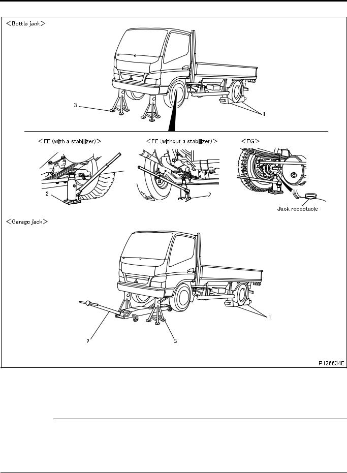
JACKING UP THE VEHICLE
<Front of Vehicle> |
Jacking up procedure
1Place chocks against the rear wheels.
2Jack up the front of the vehicle with a bottle jack or garage jack.
3Support the front of the vehicle frame on jack stands.
WARNING 
•Chock the wheels firmly to prevent the vehicle from rolling away.
•Do not attempt to remove the chocks until the operation is completed.
•It is extremely dangerous to support the vehicle with only bottle jack or garage jack. Be sure to additionally support the front of the vehicle frame on jack stands.
•Never attempt to remove the bottle jack, garage jack, or jack stands until the operation is completed.
00-26
00 |
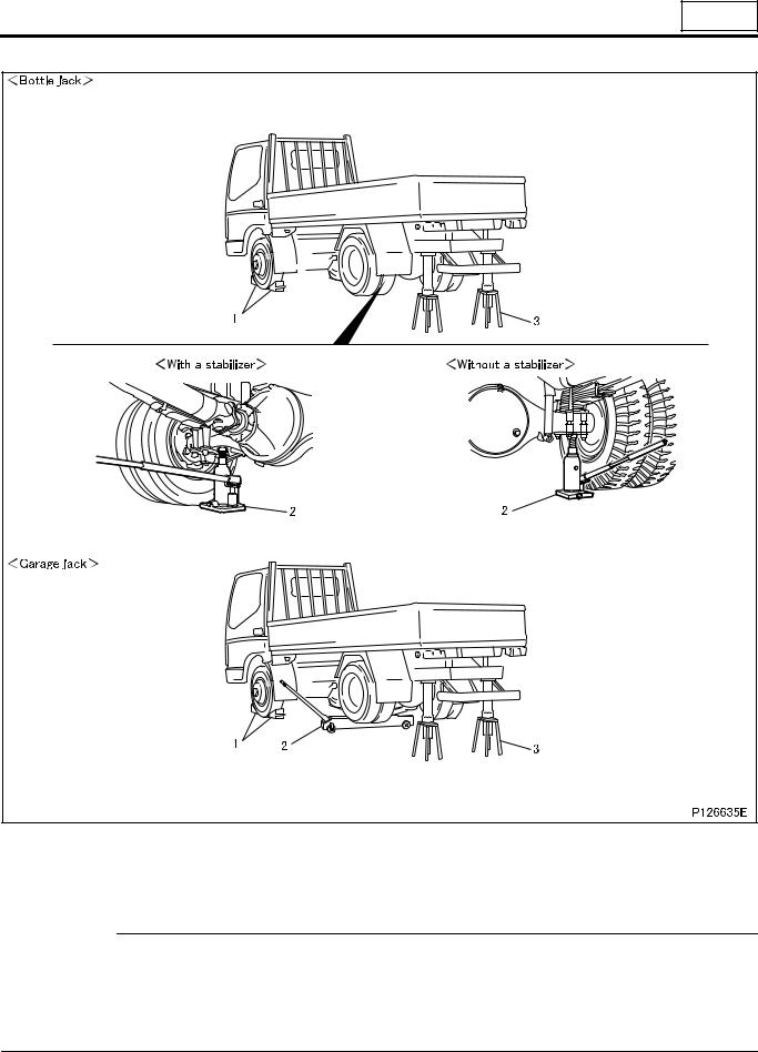
<Rear of Vehicle> |
Jacking up procedure
1Place chocks against the front wheels.
2Jack up the rear of the vehicle using a bottle jack or garage jack as illustrated above.
3Support the vehicle frame on jack stands on both sides.
WARNING 
•Chock the wheels firmly to prevent the vehicle from rolling away.
•Do not attempt to remove the chocks until the operation is completed.
•It is extremely dangerous to support the vehicle with only bottle jack or garage jack. Be sure to additionally support the vehicle frame on jack stands on both sides.
•Never attempt to remove the bottle jack, garage jack, or jack stands until the operation is completed.
00-27
DIAGNOSIS CODES
1. Diagnosis Codes
•Diagnosis codes indicate the faulty sections of the vehicle.
•A fault can be repaired by reading out the diagnosis code(s) stored in the control unit and performing the remedy for that code(s).
•Diagnosis codes can be displayed in the following two methods. Select either of them according to the system to be diagnosed.
•Using a Multi-Use Tester
•Using flashing of a warning lamp on meter cluster
•The table below indicates the systems for which diagnosis codes can be displayed and the methods usable for individual systems.
1.1 Systems and diagnosis code displaying methods
Warning lamp |
System |
Flashing of |
Reference |
|
warning lamp |
Gr |
|||
|
|
|||
Anti-lock brake system (ABS) |
|
O |
35E |
1.2 Types of diagnosis codes
(1) |
Present diagnosis code |
|
• |
Fault developed in the vehicle after the starter switch is set to ON is indicated by corresponding diagnosis code. |
|
• |
The fault warning lamp is lit at the same time. |
|
(2) |
Past diagnosis code |
|
•Past fault developed in the vehicle is indicated by corresponding diagnosis code stored in the memory of the electronic control unit.
•With the vehicle restored to its normal condition or the starter switch turned from OFF to ON after inspection or repair against present diagnosis codes, the present diagnosis code is stored as past diagnosis codes in the memory of the electronic control unit.
•The warning lamp is not lit because the indicated fault is not present one.
00-28
 Loading...