


 Loading...
MELDAS is a registered trademark of Mitsubishi Electric Corporation.
Other company and product names that appear in this manual are trademarks or registered trademarks of their respective companies.
Introduction
Thank you for selecting the Mitsubishi numerical control unit.
This instruction manual describes the handling and caution points for using this AC servo/spindle.
Incorrect handling may lead to unforeseen accidents, so always read this instruction manual thoroughly to ensure correct usage.
Make sure that this instruction manual is delivered to the end user.
Always store this manual in a safe place.
All specifications for the MDS-C1 Series are described in this manual. However, each
CNC may not be provided with all specifications, so refer to the specifications for the CNC on hand before starting use.
Notes on Reading This Manual
(1)Since the description of this specification manual deals with NC in general, for the specifications of individual machine tools, refer to the manuals issued by the respective machine manufacturers. The "restrictions" and "available functions" described in the manuals issued by the machine manufacturers have precedence to those in this manual.
(2)This manual describes as many special operations as possible, but it should be kept in mind that items not mentioned in this manual cannot be performed.
Precautions for safety
Please read this manual and auxiliary documents before starting installation, operation, maintenance or inspection to ensure correct usage. Thoroughly understand the device, safety information and precautions before starting operation.
The safety precautions in this instruction manual are ranked as "WARNING" and "CAUTION".
DANGER

 WARNING
CAUTION
When there is a potential risk of fatal or serious injuries if handling is mistaken.
When operator could be fatally or seriously injured if handling is mistaken.
When a dangerous situation may occur if handling is mistaken leading to medium or minor injuries, or physical damage.
Note that some items described as |
|
|
CAUTION |
may lead to major results depending on |
|
|
|||
|
|
|
|
|
the situation. In any case, important information that must be observed is described.
The numeric control unit is configured of the control unit, operation board, servo drive unit, spindle drive unit, power supply unit, servomotor and spindle motor, etc.
In this section "Precautions for safety", the following items are generically called the "servomotor".
•Servomotor
•Spindle motor
In this section "Precautions for safety", the following items are generically called the "servo drive unit".
•Servo drive unit
•Spindle drive unit
•Power supply unit
 WARNING
1. Electric shock prevention
Do not open the front cover while the power is ON or during operation. Failure to observe this could lead to electric shocks.
Do not operate the unit with the front cover removed. The high voltage terminals and charged sections will be exposed, and can cause electric shocks.
Do not remove the front cover even when the power is OFF unless carrying out wiring work or periodic inspections. The inside of the units is charged, and can cause electric shocks.
Wait at least 15 minutes after turning the power OFF before starting wiring, maintenance or inspections. Failure to observe this could lead to electric shocks.
Ground the servo drive unit and servomotor with Class C (former class 3) grounding or higher.
Wiring, maintenance and inspection work must be done by a qualified technician.
Wire the servo drive unit and servomotor after installation. Failure to observe this could lead to electric shocks.
Do not touch the switches with wet hands. Failure to observe this could lead to electric shocks.
Do not damage, apply forcible stress, place heavy items on the cables or get them caught. Failure to observe this could lead to electric shocks.
CAUTION
1. Fire prevention
Install the servo drive units, servomotors and regenerative resistor on noncombustible material. Direct installation on combustible material or near combustible materials could lead to fires.
Shut off the power on the servo drive unit side if the servo drive unit fails. Fires could be caused if a large current continues to flow.
When using a regenerative resistor, provide a sequence that shuts off the power with the regenerative resistor's error signal. The regenerative resistor could abnormally overheat and cause a fire due to a fault in the regenerative transistor, etc.
The battery unit could heat up, ignite or rupture if submerged in water, or if the poles are incorrectly wired.
2. Injury prevention
Do not apply a voltage other than that specified in Instruction Manual on each terminal. Failure to observe this item could lead to ruptures or damage, etc.
Do not mistake the terminal connections. Failure to observe this item could lead to ruptures or damage, etc.
Do not mistake the polarity ( + , – ). Failure to observe this item could lead to ruptures or damage, etc.
The servo drive unit's fins, regenerative resistor and servomotor, etc., may reach high temperatures while the power is ON, and may remain hot for some time after the power is turned OFF. Touching these parts could result in burns.
CAUTION
3. Various precautions
Observe the following precautions. Incorrect handling of the unit could lead to faults, injuries and electric shocks, etc.
(1) Transportation and installation
Correctly transport the product according to its weight.
Use the servomotor's hanging bolts only when transporting the servomotor. Do not transport the servomotor when it is installed on the machine.
Do not stack the products above the tolerable number.
Do not hold the cables, axis or detector when transporting the servomotor.
Do not hold the connected wires or cables when transporting the servo drive units.
Do not hold the front cover when transporting the servo drive units. The unit could drop.
Follow this Instruction Manual and install in a place where the weight can be borne.
Do not get on top of or place heavy objects on the unit.
Always observe the installation directions.
Secure the specified distance between the servo drive unit and control panel's inner wall, and between other devices.
Do not install or run a servo drive unit or servomotor that is damaged or missing parts.
Do not block the intake or exhaust ports of the servomotor provided with a cooling fan.
Do not let foreign objects enter the servo drive units or servomotors. In particular, if conductive objects such as screws or metal chips, etc., or combustible materials such as oil enter, rupture or breakage could occur.
The servo drive units and servomotors are precision devices, so do not drop them or apply strong impacts to them.

CAUTION
 Store and use the units under the following environment conditions.
Environment |
Conditions |
||
Servo drive unit |
Servomotor |
||
|
|||
Ambient temperature |
0°C to +55°C (with no freezing) |
0°C to +40°C (with no freezing) |
|
Ambient humidity |
90%RH or less |
80% RH or less |
|
(with no dew condensation) |
(with no dew condensation) |
||
|
|||
Storage temperature |
-15°C to +70°C |
||
Storage humidity |
90%RH or less (with no dew condensation) |
||
Atmosphere |
Indoors (where unit is not subject to direct sunlight), |
||
with no corrosive gas, combustible gas, oil mist, |
|||
|
dust or conductive particles |
||
Altitude |
1,000m or less above sea level |
||
Vibration |
4.9m/s2 (0.5G) or less |
To follow each unit and motor |
|
|
|
specifications |
|
Securely fix the servomotor to the machine. Insufficient fixing could lead to the servomotor slipping off during operation.
Always install the servomotor with reduction gear in the designated direction. Failure to do so could lead to oil leaks.
Structure the rotary sections of the motor so that it can never be touched during operation. Install a cover, etc., on the shaft.
When installing a coupling to a servomotor shaft end, do not apply an impact by hammering, etc. The detector could be damaged.
Do not apply a load exceeding the tolerable load onto the servomotor shaft. The shaft could break.
Store the motor in the package box.
When inserting the shaft into the built-in IPM motor, do not heat the rotor higher than 130°C. The magnet could be demagnetized, and the specifications characteristics will not be ensured.
If the unit has been stored for a long time, always check the operation before starting actual operation. Please contact the Service Center or Service Station.

CAUTION
(2) Wiring
Correctly and securely perform the wiring. Failure to do so could lead to runaway of the servomotor.
Do not install a condensing capacitor, surge absorber or radio noise filter on the output side of the servo drive unit.
Correctly connect the output side (terminals U, V, W). Failure to do so could lead to abnormal operation of the servomotor.
Do not directly connect a commercial power supply to the servomotor. Failure to observe this could result in a fault.
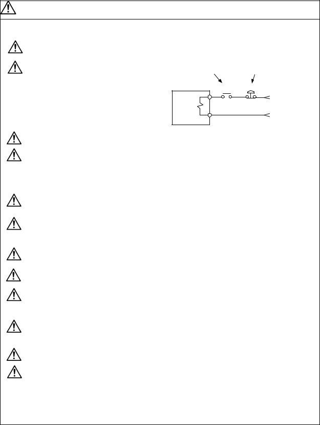
When using an inductive load such as a relay, always connect a diode as a noise measure parallel to the load.
Servodrive unit
COM |
|
|
(24VDC) |
|
|
Control output |
RA |
|
signal |
||
|
Servodrive unit |
|
|
COM |
|
|
(24VDC) |
|
|
Control output |
RA |
|
signal |
||
|
When using a capacitance load such as a lamp, always connect a protective resistor as a noise measure serial to the load.
Do not reverse the direction of a diode which connect to a DC relay for the control output signals to suppress a surge. Connecting it backwards could cause the drive unit to malfunction so that signals are not output, and emergency stop and other safety circuits are inoperable.
Do not connect/disconnect the cables connected between the units while the power is ON.
Securely tighten the cable connector fixing screw or fixing mechanism. An insecure fixing could cause the cable to fall off while the power is ON.
When using a shielded cable instructed in the connection manual, always ground the cable with a cable clamp, etc.
Always separate the signals wires from the drive wire and power line.
Use wires and cables that have a wire diameter, heat resistance and flexibility that conforms to the system.
CAUTION
(3) Trial operation and adjustment
Check and adjust each program and parameter before starting operation. Failure to do so could lead to unforeseen operation of the machine.
Do not make remarkable adjustments and changes as the operation could become unstable.
(4) Usage methods
Install an external emergency stop circuit so that the operation can be stopped and power shut off immediately.
Turn the power OFF immediately if smoke, abnormal noise or odors are generated from the servo drive unit or servomotor.
Unqualified persons must not disassemble or repair the unit. Never make modifications.
Reduce magnetic damage by installing a noise filter. The electronic devices used near the servo drive unit could be affected by magnetic noise.
Use the servo drive unit, servomotor and regenerative resistor with the designated combination. Failure to do so could lead to fires or trouble.
The brake (magnetic brake) assembled into the servomotor is for holding, and must not be used for normal braking.
There may be cases when holding is not possible due to the magnetic brake's life or the machine construction (when ball screw and servomotor are coupled via a timing belt, etc.). Install a stop device to ensure safety on the machine side.
After changing the programs/parameters or after maintenance and inspection, always test the operation before starting actual operation.
Do not enter the movable range of the machine during automatic operation. Never place body parts near or touch the spindle during rotation.
Follow the power supply specification conditions given in the separate specifications manual for the power (input voltage, input frequency, tolerable sudden power failure time, etc.).
Set all bits to "0" if they are indicated as not used or empty in the explanation on the bits.
Do not use the dynamic brakes except during the emergency stop. Continued use of the dynamic brakes could result in brake damage.
If a breaker is shared by several power supply units, the breaker may not activate when a short-circuit fault occurs in a small capacity unit. This is dangerous, so never share the breakers.
CAUTION
(5) Troubleshooting
If a hazardous situation is predicted during power failure or product trouble, use a servomotor with magnetic brakes or install an external brake mechanism.
Use a double circuit configuration that allows the operation circuit for the magnetic brakes to be operated even by the external emergency stop signal.
Shut off with the servomotor brake control output.
Servomotor MBR
Magnetic brake
Shut off with NC brake control PLC output.
EMG
24VDC
Always turn the input power OFF when an alarm occurs.
Never go near the machine after restoring the power after a power failure, as the machine could start suddenly. (Design the machine so that personal safety can be ensured even if the machine starts suddenly.)
(6) Maintenance, inspection and part replacement
Always carry out maintenance and inspection after backing up the servo drive unit's programs or parameters.
The capacity of the electrolytic capacitor will drop over time. To prevent secondary disasters due to failures, replacing this part every five years when used under a normal environment is recommended. Contact the Service Center or Service Station for replacement.
Do not perform a megger test (insulation resistance measurement) during inspections.
If the battery low warning is issued, save the machining programs, tool data and parameters with an input/output unit, and then replace the battery.
Do not short circuit, charge, overheat, incinerate or disassemble the battery.
(7) Disposal
Treat this unit as general industrial waste. Note that MDS Series unit with a heat dissipating fin protruding from the back of the unit contains substitute Freon. Do not dispose of this type of unit as general industrial waste. Always return to the Service Center or Service Station.
Do not disassemble the servo drive unit or servomotor parts.
Dispose of the battery according to local laws.
(8) General precautions
The drawings given in this Specifications and Maintenance Instruction Manual show the covers and safety partitions, etc., removed to provide a clearer explanation. Always return the covers or partitions to their respective places before starting operation, and always follow the instructions given in this manual.
CONTENTS
1. Installation |
|
||
1-1 |
Installation of servomotor..................................................................................................... |
1-2 |
|
1-1-1 |
Environmental conditions .............................................................................................. |
1-2 |
|
1-1-2 |
Quakeproof level............................................................................................................ |
1-2 |
|
1-1-3 Cautions for mounting load (prevention of impact on shaft) ......................................... |
1-3 |
||
1-1-4 |
Installation direction ....................................................................................................... |
1-3 |
|
1-1-5 |
Shaft characteristics ...................................................................................................... |
1-4 |
|
1-1-6 |
Oil/water standards........................................................................................................ |
1-5 |
|
1-1-7 |
Cable stress ................................................................................................................... |
1-7 |
|
1-2 Installation of spindle motor................................................................................................. |
1-8 |
||
1-2-1 |
Environmental conditions .............................................................................................. |
1-8 |
|
1-2-2 |
Shaft characteristics ...................................................................................................... |
1-9 |
|
1-3 Installation of the control unit............................................................................................. |
1-10 |
||
1-3-1 |
Environmental conditions ............................................................................................ |
1-10 |
|
1-3-2 Installation direction and clearance............................................................................. |
1-11 |
||
1-3-3 Prevention of entering of foreign matter...................................................................... |
1-11 |
||
1-3-4 Panel installation hole work drawings (Panel cut drawings)....................................... |
1-12 |
||
1-3-5 |
Heating value............................................................................................................... |
1-13 |
|
1-3-6 |
Heat radiation countermeasures ................................................................................. |
1-14 |
|
1-4 Installing the spindle detector ............................................................................................ |
1-16 |
||
1-4-1 |
Magnetic sensor .......................................................................................................... |
1-16 |
|
1-4-2 |
Spindle end detector.................................................................................................... |
1-18 |
|
1-4-3 |
Spindle end PLG.......................................................................................................... |
1-19 |
|
1-5 |
Noise measures................................................................................................................. |
1-22 |
|
2. Wiring and Connection |
|
||
2-1 Part system connection diagram ......................................................................................... |
2-3 |
||
2-2 Main circuit terminal block/control circuit connector............................................................ |
2-4 |
||
2-2-1 Names and applications of main circuit terminal block signals and control circuit |
|
||
|
|
connectors ..................................................................................................................... |
2-4 |
2-2-2 |
Connector pin assignment............................................................................................. |
2-5 |
|
2-3 NC and drive unit connection ......................................................................................................... |
2-8 |
||
2-4 Motor and detector connection ..................................................................................................... |
2-11 |
||
2-4-1 |
Connecting the servomotor ......................................................................................... |
2-11 |
|
2-4-2 Connecting the full-closed loop system....................................................................... |
2-18 |
||
2-4-3 Connecting the synchronous control system .............................................................. |
2-22 |
||
2-4-4 Connection of the spindle motor.................................................................................. |
2-28 |
||
2-5 Connection of power supply .............................................................................................. |
2-33 |
||
2-5-1 Power supply input connection ...................................................................................... |
2-34 |
||
2-5-2 Connecting the grounding cable.................................................................................. |
2-37 |
||
2-5-3 Main circuit control ......................................................................................................... |
2-38 |
||
2-6 Wiring of the motor brake .................................................................................................. |
2-39 |
||
2-6-1 Wiring of the motor magnetic brake ............................................................................ |
2-39 |
||
2-6-2 Dynamic brake unit wiring ........................................................................................... |
2-41 |
||
2-7 Peripheral control wiring....................................................................................................... |
2-42 |
||
2-7-1 Input/output circuit wiring ............................................................................................... |
2-42 |
||
2-7-2 |
Spindle coil changeover .............................................................................................. |
2-43 |
|
2-7-3 Wiring of an external emergency stop......................................................................... |
2-46 |
||
3. Setup |
|
|
|
3-1 |
Initial setup ........................................................................................................................... |
3-2 |
|
3-1-1 Setting the rotary switch ................................................................................................ |
3-2 |
||
3-1-2 Transition of LED display after power is turned ON...................................................... |
3-3 |
||
3-1-3 Servo standard specifications and high-gain specifications ......................................... |
3-4 |
||
3-2 Setting the initial parameters for the servo drive unit (High-gain specifications)................ |
3-5 |
||
3-2-1 Setting the standard parameters................................................................................... |
3-5 |
||
3-2-2 List of standard parameters for each servomotor ....................................................... |
3-11 |
||
3-2-3 |
Servo parameter list..................................................................................................... |
3-23 |
|
3-3 Setting the initial parameters for the servo drive unit (Standard specifications)............... |
3-39 |
||
3-3-1 Setting the standard parameters................................................................................. |
3-39 |
||
3-3-2 List of standard parameters for each servomotor ....................................................... |
3-44 |
||
3-3-3 |
Servo parameter list..................................................................................................... |
3-51 |
|
3-4 Restrictions on servo control ............................................................................................. |
3-63 |
||
3-4-1 Restrictions of electronic gear setting value................................................................ |
3-63 |
||
3-4-2 Restrictions on absolute position control..................................................................... |
3-64 |
||
3-5 Setting the initial parameters for the spindle drive unit ..................................................... |
3-65 |
||
3-5-1 |
Spindle specification parameters ................................................................................ |
3-65 |
|
3-5-2 List of spindle parameters ........................................................................................... |
3-70 |
||
3-6 Initial adjustment of the spindle PLG............................................................................... |
3-104 |
||
3-6-1 Adjusting the PLG installation.................................................................................... |
3-104 |
||
3-6-2 Z phase automatic adjustment .................................................................................. |
3-110 |
||
3-6-3 Motor end PLG automatic adjustment....................................................................... |
3-111 |
||
3-6-4 Spindle end PLG automatic adjustment.................................................................... |
3-112 |
||
4. Servo Adjustment |
|
||
4-1 D/A output specifications for servo drive unit ...................................................................... |
4-2 |
||
4-1-1 |
D/A output specifications ............................................................................................... |
4-2 |
|
4-1-2 |
Output data settings....................................................................................................... |
4-3 |
|
4-1-3 Setting the output magnification .................................................................................... |
4-3 |
||
4-2 |
Gain adjustment................................................................................................................... |
4-4 |
|
4-2-1 |
Current loop gain ........................................................................................................... |
4-4 |
|
4-2-2 |
Speed loop gain............................................................................................................. |
4-4 |
|
4-2-3 |
Position loop gain .......................................................................................................... |
4-6 |
|
4-3 |
Characteristics improvement ............................................................................................... |
4-9 |
|
4-3-1 Optimal adjustment of cycle time .................................................................................. |
4-9 |
||
4-3-2 |
Vibration suppression measures................................................................................. |
4-11 |
|
4-3-3 Improving the cutting surface precision....................................................................... |
4-15 |
||
4-3-4 Improvement of characteristics during acceleration/deceleration .............................. |
4-19 |
||
4-3-5 Improvement of protrusion at quadrant changeover................................................... |
4-22 |
||
4-3-6 |
Improvement of overshooting...................................................................................... |
4-29 |
|
4-3-7 Improvement of the interpolation control path............................................................. |
4-31 |
||
4-4 Adjustment during full closed loop control......................................................................... |
4-33 |
||
4-4-1 Outline.......................................................................................................................... |
4-33 |
||
4-4-2 Speed loop delay compensation ................................................................................. |
4-34 |
||
4-4-3 Dual feedback control (Optional function)................................................................... |
4-35 |
||
4-5 Settings for emergency stop.............................................................................................. |
4-37 |
||
4-5-1 |
Deceleration control..................................................................................................... |
4-37 |
|
4-5-2 Vertical axis drop prevention control ........................................................................... |
4-39 |
||
4-6 |
Protective functions............................................................................................................ |
4-43 |
|
4-6-1 |
Overload detection....................................................................................................... |
4-43 |
|
4-6-2 |
Excessive error detection ............................................................................................ |
4-43 |
|
4-6-3 |
Collision detection........................................................................................................ |
4-44 |
|
5. Spindle Adjustment |
|
||
5-1 D/A output specifications for spindle drive unit ................................................................... |
5-2 |
||
5-1-1 |
D/A output specifications ............................................................................................... |
5-2 |
|
5-1-2 Setting the output data .................................................................................................. |
5-3 |
||
5-1-3 Setting the output magnification .................................................................................... |
5-4 |
||
5-2 |
Spindle control signal........................................................................................................... |
5-6 |
|
5-2-1 Spindle control input (NC to SP) ................................................................................... |
5-6 |
||
5-2-2 Spindle control output (SP to NC) ............................................................................... |
5-15 |
||
5-3 Adjustment procedures for each control ........................................................................... |
5-26 |
||
5-3-1 |
Basic adjustments........................................................................................................ |
5-26 |
|
5-3-2 Adjusting the acceleration/deceleration operation ...................................................... |
5-27 |
||
5-3-3 Adjusting the orientation control .................................................................................. |
5-36 |
||
5-3-4 Adjusting the synchronous tap control ........................................................................ |
5-50 |
||
5-3-5 Adjusting the C-axis control......................................................................................... |
5-54 |
||
5-3-6 Adjusting the spindle synchronous control.................................................................. |
5-57 |
||
6. Troubleshooting |
|
||
6-1 Points of caution and confirmation ...................................................................................... |
6-2 |
||
6-1-1 LED display when alarm or warning occurs.................................................................. |
6-3 |
||
6-2 Protective functions list of units ........................................................................................... |
6-4 |
||
6-2-1 |
List of alarms.................................................................................................................. |
6-4 |
|
6-2-2 |
List of warnings.............................................................................................................. |
6-9 |
|
6-3 |
Troubleshooting ................................................................................................................. |
6-10 |
|
6-3-1 Troubleshooting at power ON ..................................................................................... |
6-10 |
||
6-3-2 Troubleshooting for each alarm No............................................................................. |
6-11 |
||
6-3-3 Troubleshooting for each warning No. ........................................................................ |
6-40 |
||
6-3-4 Parameter numbers during initial parameter error...................................................... |
6-44 |
||
6-3-5 Troubleshooting the spindle system when there is no alarm or warning ................... |
6-45 |
||
7. Maintenance |
|
||
7-1 |
Inspections........................................................................................................................... |
7-2 |
|
7-2 |
Service parts ........................................................................................................................ |
7-2 |
|
7-3 Adding and replacing units and parts .................................................................................. |
7-3 |
||
7-3-1 Replacing the drive unit ................................................................................................. |
7-3 |
||
7-3-2 Replacing the unit fan.................................................................................................... |
7-4 |
||
Appendix 1. Cable and Connector Specifications |
|
||
Appendix 1-1 Selection of cable .............................................................................................. |
A1-2 |
||
Appendix 1-1-1 Cable wire and assembly ............................................................................ |
A1-2 |
||
Appendix 1-1-2 Flexible conduits.......................................................................................... |
A1-4 |
||
Appendix 1-2 Cable connection diagram................................................................................. |
A1-6 |
||
Appendix 1-3 Connector outline dimension drawings ........................................................... |
A1-13 |
||
Appendix 2. Compliance to EC Directives |
|
||
Appendix 2-1 Compliance to EC Directives ............................................................................ |
A2-2 |
||
Appendix 2-1-1 European EC Directives.............................................................................. |
A2-2 |
||
Appendix 2-1-2 Cautions for EC Directive compliance........................................................... |
A2-2 |
||
Appendix 3. EMC Installation Guidelines |
|
||
Appendix 3-1 |
Introduction ........................................................................................................ |
A3-2 |
|
Appendix 3-2 |
EMC instructions ............................................................................................... |
A3-2 |
|
Appendix 3-3 |
EMC measures.................................................................................................. |
A3-3 |
|
Appendix 3-4 Measures for panel structure............................................................................. |
A3-3 |
||
Appendix 3-4-1 Measures for control panel unit................................................................... |
A3-3 |
||
Appendix 3-4-2 Measures for door ....................................................................................... |
A3-4 |
||
Appendix 3-4-3 Measures for operation board panel........................................................... |
A3-4 |
||
Appendix 3-4-4 Shielding of the power supply input section................................................ |
A3-4 |
||
Appendix 3-5 Measures for various cables ............................................................................. |
A3-5 |
||
Appendix 3-5-1 Measures for wiring in panel ....................................................................... |
A3-5 |
||
Appendix 3-5-2 Measures for shield treatment..................................................................... |
A3-5 |
||
Appendix 3-5-3 Servo/spindle motor power cable................................................................ |
A3-6 |
||
Appendix 3-5-4 Servo motor feedback cable ....................................................................... |
A3-7 |
||
Appendix 3-5-5 Spindle motor feedback cable..................................................................... |
A3-7 |
||
Appendix 3-6 EMC countermeasure parts .............................................................................. |
A3-8 |
||
Appendix 3-6-1 Shield clamp fitting ...................................................................................... |
A3-8 |
||
Appendix 3-6-2 |
Ferrite core .................................................................................................. |
A3-9 |
|
Appendix 3-6-3 |
Power line filter .......................................................................................... |
A3-10 |
|
Appendix 3-6-4 |
Surge protector.......................................................................................... |
A3-15 |
|
Appendix 4. Servo/spindle drive unit categories based on higher harmonic suppression countermeasure guidelines
Appendix 4-1 Servo/spindle drive unit circuit categories based on higher harmonic suppression
countermeasure guidelines............................................................................... |
A4-2 |
Contents for MDS-C1 Series SPECIFICATIONS MANUAL (BNP-C3040D)
1. Introduction |
|
||
1-1 Servo/spindle drive system configuration............ |
1-2 |
||
1-1-1 |
System configuration ................................................. |
1-2 |
|
1-1-2 |
Unit outline type......................................................... |
1-3 |
|
1-2 |
Explanation of type.............................................. |
1-4 |
|
1-2-1 |
Servomotor type ........................................................ |
1-4 |
|
1-2-2 Servo drive unit type.................................................. |
1-8 |
||
1-2-3 |
Spindle motor type..................................................... |
1-10 |
|
1-2-4 Spindle drive unit type ............................................... |
1-12 |
||
1-2-5 Power supply unit type............................................... |
1-13 |
||
1-2-6 |
AC reactor type.......................................................... |
1-14 |
|
2. Specifications |
|
||
2-1 |
Servomotor.......................................................... |
2-2 |
|
2-1-1 |
Specifications list ....................................................... |
2-2 |
|
2-1-2 |
Torque characteristics ............................................... |
2-7 |
|
2-2 |
Spindle motor ...................................................... |
2-10 |
|
2-2-1 Specifications ............................................................ |
2-10 |
||
2-2-2 |
Output characteristics................................................ |
2-15 |
|
2-3 |
Drive unit ............................................................. |
2-20 |
|
2-3-1 |
Servo drive unit.......................................................... |
2-20 |
|
2-3-2 |
Spindle drive unit ....................................................... |
2-22 |
|
2-3-3 |
Power supply unit ...................................................... |
2-23 |
|
2-3-4 |
AC reactor ................................................................. |
2-24 |
|
2-3-5 D/A output specifications for servo drive unit ............. |
2-25 |
||
2-3-6 D/A output specifications for spindle drive unit........... |
2-26 |
||
2-3-7 Explanation of each part ............................................ |
2-27 |
||
2-4 Restrictions on servo control............................... |
2-30 |
||
2-4-1 Restrictions of electronic gear setting value............... |
2-30 |
||
2-4-2 Restrictions on absolute position control.................... |
2-32 |
||
3. Characteristics |
|
||
3-1 |
Servomotor.......................................................... |
3-2 |
|
3-1-1 |
Environmental conditions........................................... |
3-2 |
|
3-1-2 |
Quakeproof level ....................................................... |
3-2 |
|
3-1-3 |
Shaft characteristics .................................................. |
3-3 |
|
3-1-4 |
Oil/water standards.................................................... |
3-4 |
|
3-1-5 |
Magnetic brake.......................................................... |
3-5 |
|
3-1-6 |
Dynamic brake characteristics ................................... |
3-8 |
|
3-2 |
Spindle motor ...................................................... |
3-10 |
|
3-2-1 |
Environmental conditions........................................... |
3-10 |
|
3-2-2 |
Shaft characteristics .................................................. |
3-10 |
|
3-3 |
Drive unit characteristics ..................................... |
3-11 |
|
3-3-1 |
Environmental conditions........................................... |
3-11 |
|
3-3-2 |
Heating value............................................................. |
3-12 |
|
3-3-3 |
Overload protection characteristics............................ |
3-13 |
|
4. Dedicated Options |
|
||
4-1 |
Servo options ...................................................... |
4-2 |
|
4-1-1 Battery and terminator option (mandatory selection).. |
4-3 |
||
4-1-2 Dynamic brake unit (MDS-B-DBU) |
|
||
|
|
(mandatory selection for large capacity).................... |
4-5 |
4-1-3 Ball screw end detector ............................................. |
4-7 |
||
4-1-4 |
Machine end detector ................................................ |
4-8 |
|
4-1-5 Detector conversion unit (MDS-B-HR) ....................... |
4-10 |
||
4-1-6 Signal divider unit (MDS-B-SD) ................................. |
4-12 |
||
4-2 |
Spindle option ..................................................... |
4-14 |
|
4-2-1 |
Magnetic sensor ........................................................ |
4-16 |
|
4-2-2 |
Spindle end detector |
|
|
|
|
(OSE-1024-3-15-68, OSE-1024-3-15-68-8) .............. |
4-18 |
4-2-3 |
C-axis detector (OSE90K) ......................................... |
4-20 |
|
4-2-4 |
C-axis detector (MBE90K)......................................... |
4-22 |
|
4-2-5 |
C-axis detector (MHE90K)......................................... |
4-23 |
|
4-2-6 Spindle end PLG (MXE128/180/256/512).................. |
4-24 |
||
4-2-7 Detector conversion unit (MDS-B-PJEX) ................... |
4-28 |
||
4-3 |
Cables and connectors ....................................... |
4-30 |
|
4-3-1 |
Cable connection diagram......................................... |
4-30 |
|
4-3-2 List of cables and connectors .................................... |
4-31 |
||
5. Peripheral Devices |
|
||
5-1 Selecting the wire size ........................................ |
5-2 |
||
5-2 Selection the AC reactor, contactor |
|
||
|
|
and no-fuse breaker ........................................... |
5-5 |
5-2-1 |
Standard selection..................................................... |
5-5 |
|
5-2-2 Selection when a contactor is shared ........................ |
5-6 |
||
5-3 |
Circuit protector .................................................. |
5-7 |
|
5-4 |
Circuit protector .................................................. |
5-8 |
|
5-5 |
Noise filter........................................................... |
5-9 |
|
5-6 |
Surge absorber ................................................... |
5-10 |
|
5-7 Speedometer and load meter ............................. |
5-11 |
||
5-8 Cable for peripheral control ................................ |
5-12 |
||
5-8-1 Cable for external emergency stop............................ |
5-12 |
||
5-8-2 Cable for servomotor magnetic brake........................ |
5-13 |
||
Appendix 1. Outline Dimension Drawings
Appendix 1-1 Servomotor outline dimension drawings
|
............................................................ |
A1-2 |
Appendix 1-1-1 |
HC Series .................................................. |
A1-2 |
Appendix 1-1-2 |
HA Series .................................................. |
A1-8 |
Appendix 1-2 Outline dimension drawings |
|
|
|
of spindle motor................................... |
A1-12 |
Appendix 1-2-1 |
SJ Series ................................................... |
A1-12 |
Appendix 1-2-2 |
SJ-V Series................................................ |
A1-15 |
Appendix 1-2-3 |
SJ-VS Series ............................................. |
A1-25 |
Appendix 1-2-4 SJ-PMF Series (IPM motor)....................... |
A1-27 |
|
Appendix 1-3 Unit outline dimension drawings ......... |
A1-28 |
|
Appendix 1-3-1 Servo/spindle drive unit ............................. |
A1-28 |
|
Appendix 1-3-2 Power supply unit ...................................... |
A1-37 |
|
Appendix 1-3-3 |
AC rector ................................................... |
A1-41 |
Appendix 2. Table and Connector Specifications |
|
|
Appendix 2-1 Selection of cable ............................... |
A2-2 |
|
Appendix 2-1-1 Cable wire and assembly........................... |
A2-2 |
|
Appendix 2-1-2 |
Flexible conduits........................................ |
A2-4 |
Appendix 2-2 Cable connection diagram .................. |
A2-6 |
|
Appendix 2-3 Connector outline dimension drawings |
||
|
............................................................ |
A2-12 |
Appendix 3. Selection |
|
|
Appendix 3-1 Selecting the servomotor series ......... |
A3-2 |
|
Appendix 3-1-1 Motor series characteristics ....................... |
A3-2 |
|
Appendix 3-1-2 |
Servomotor precision................................. |
A3-3 |
Appendix 3-2 Selection of servomotor capacity........ |
A3-4 |
|
Appendix 3-2-1 |
Load inertia ratio........................................ |
A3-4 |
Appendix 3-2-2 Short time characteristics........................... |
A3-4 |
|
Appendix 3-2-3 |
Continuous characteristics......................... |
A3-5 |
(Note) This is the content for SPECIFICATION MANUAL version D. The structure of section and page number may be different other than version D.
Contents for MDS-C1 Series SPECIFICATIONS MANUAL (BNP-C3040D)
Appendix 3-3 Example of servo selection ................. |
A3-7 |
|
Appendix 3-3-1 Motor selection calculation......................... |
A3-7 |
|
Appendix 3-3-2 Servo selection results............................... |
A3-10 |
|
Appendix 3-3-3 Motor shaft conversion load torque............ |
A3-11 |
|
Appendix 3-3-4 Expressions for load inertia calculation ...... |
A3-12 |
|
Appendix 3-4 Selecting the power supply ................. |
A3-13 |
|
Appendix 3-4-1 |
Selecting according to the continuous rated |
|
|
capacity..................................................... |
A3-13 |
Appendix 3-4-2 |
Selection with maximum momentary capacity |
|
|
.................................................................. |
A3-14 |
Appendix 3-4-3 |
Selection example...................................... |
A3-15 |
Appendix 4. Explanation of Large Capacity Spindle Unit Specifications
Appendix 4-1 Explanation of large capacity spindle unit
|
specifications ....................................... |
A4-2 |
|
Appendix 4-1-1 |
|
Outline ....................................................... |
A4-2 |
Appendix 4-1-2 |
|
List of units................................................. |
A4-2 |
Appendix 4-1-3 Selection of AC reactor (B-AL), |
|
||
|
|
contactor and NFB .................................... |
A4-2 |
Appendix 4-1-4 Outline dimension drawings ....................... |
A4-3 |
||
Appendix 4-1-5 Panel cut dimension drawing ..................... |
A4-8 |
||
Appendix 4-1-6 |
|
Heating value............................................. |
A4-9 |
Appendix 4-1-7 Selecting the power capacity ..................... |
A4-9 |
||
Appendix 4-1-8 Selecting the wire size ............................... |
A4-9 |
||
Appendix 4-1-9 |
Drive unit connection screw size................ |
A4-10 |
|
Appendix 4-1-10 Connecting each unit ............................... |
A4-10 |
||
Appendix 4-1-11 |
Restrictions .............................................. |
A4-12 |
|
Appendix 4-1-12 |
Parameters .............................................. |
A4-14 |
|
Appendix 4-1-13 |
Precautions.............................................. |
A4-14 |
|
Appendix 5. Transportation Restrictions for Lithium Batteries
Appendix 5-1 |
Transportation restrictions |
|
|
for lithium batteries .............................. |
A5-2 |
Appendix 5-1-1 |
Target products.......................................... |
A5-2 |
Appendix 5-1-2 |
Handling by user........................................ |
A5-3 |
Appendix 5-1-3 Regulations enforcement timing................. |
A5-4 |
|
Appendix 6. Compliance to EU EC Directives |
|
|
Appendix 6-1 |
Compliance to EC Directives .............. |
A6-2 |
Appendix 6-1-1 |
European EC Directives............................. |
A6-2 |
Appendix 6-2-2 Cautions for EC Directive compliance .......... |
A6-2 |
|
Appendix 7. EMS Instruction Guidelines |
|
|
Appendix 7-1 |
Introduction ......................................... |
A7-2 |
Appendix 7-2 |
EMC instructions................................. |
A7-2 |
Appendix 7-3 |
EMC measures ................................... |
A7-3 |
Appendix 7-4 Measures for panel structure .............. |
A7-3 |
|
Appendix 7-4-1 Measures for control panel unit.................. |
A7-3 |
|
Appendix 7-4-2 Measures for door...................................... |
A7-4 |
|
Appendix 7-4-3 Measures for operation board panel .......... |
A7-4 |
|
Appendix 7-4-4 Shielding of the power supply input section |
||
|
.................................................................. |
A7-4 |
Appendix 7-5 Measures for various cables............... |
A7-5 |
|
Appendix 7-5-1 Measures for wiring in panel ...................... |
A7-5 |
|
Appendix 7-5-2 Measures for shield treatment ................... |
A7-5 |
|
Appendix 7-5-3 Servomotor power cable............................ |
A7-6 |
|
Appendix 7-5-4 Servomotor feedback cable ....................... |
A7-6 |
|
Appendix 7-5-5 Spindle motor power cable ........................ |
A7-7 |
|
Appendix 7-5-6 Spindle motor feedback cable.................... |
A7-7 |
|
Appendix 7-6 EMC countermeasure parts................ |
A7-8 |
|
Appendix 7-6-1 Shield clamp fitting..................................... |
A7-8 |
|
Appendix 7-6-2 |
Ferrite core ................................................ |
A7-9 |
Appendix 7-6-3 |
Power line filter .......................................... |
A7-10 |
Appendix 7-6-4 |
Surge protector.......................................... |
A7-15 |
Appendix 8. Instruction Manual for Compliance with UL/c-UL
Standard |
|
|
Appendix 8. Instruction Manual for Compliance |
|
|
|
with UL/c-UL Standard ........................ |
A8-2 |
Appendix 9. Compliance with China Compulsory Product |
||
Certification (CCC Certification) System |
|
|
Appendix 9-1 Outline of China Compulsory Product |
|
|
|
Certification System ............................ |
A9-2 |
Appendix 9-2 |
First Catalogue of Products subject to |
|
|
Compulsory Product Certification........ |
A9-2 |
Appendix 9-3 |
Precautions for Shipping Products ..... |
A9-3 |
Appendix 9-4 |
Application for Exemption ................... |
A9-4 |
Appendix 9-5 |
Mitsubishi NC Product Subject to |
|
|
/Not Subject to CCC Certification........ |
A9-5 |
(Note) This is the content for SPECIFICATION MANUAL version D. The structure of section and page number may be different other than version D.

1. Installation
1-1 Installation of servomotor ................................................................................................................... |
1-2 |
|
1-1-1 |
Environmental conditions ............................................................................................................ |
1-2 |
1-1-2 |
Quakeproof level ......................................................................................................................... |
1-2 |
1-1-3 |
Cautions for mounting load (prevention of impact on shaft) ....................................................... |
1-3 |
1-1-4 |
Installation direction..................................................................................................................... |
1-3 |
1-1-5 |
Shaft characteristics .................................................................................................................... |
1-4 |
1-1-6 |
Oil/water standards ..................................................................................................................... |
1-5 |
1-1-7 |
Cable stress ................................................................................................................................ |
1-7 |
1-2 Installation of spindle motor ............................................................................................................... |
1-8 |
|
1-2-1 |
Environmental conditions ............................................................................................................ |
1-8 |
1-2-2 |
Shaft characteristics .................................................................................................................... |
1-9 |
1-3 Installation of the control unit ........................................................................................................... |
1-10 |
|
1-3-1 |
Environmental conditions .......................................................................................................... |
1-10 |
1-3-2 |
Installation direction and clearance........................................................................................... |
1-11 |
1-3-3 |
Prevention of entering of foreign matter.................................................................................... |
1-11 |
1-3-4 |
Panel installation hole work drawings (Panel cut drawings) ..................................................... |
1-12 |
1-3-5 |
Heating value............................................................................................................................. |
1-13 |
1-3-6 |
Heat radiation countermeasures ............................................................................................... |
1-14 |
1-4 Installing the spindle detector........................................................................................................... |
1-16 |
|
1-4-1 |
Magnetic sensor ........................................................................................................................ |
1-16 |
1-4-2 |
Spindle end detector ................................................................................................................. |
1-18 |
1-4-3 Spindle end PLG ....................................................................................................................... |
1-19 |
|
1-5 Noise measures ............................................................................................................................... |
1-22 |
|
1 - 1
1. Installation
1-1 Installation of servomotor
|
|
|
1. Do not hold the cables, axis or detector when transporting the motor. Failure to |
|||||
|
|
|
observe this could lead to faults or injuries. |
|
|
|||
|
|
|
2. Securely fix the motor to the machine. Insufficient fixing could lead to the |
|||||
|
|
|
motor deviating during operation. Failure to observe this could lead to |
|||||
|
|
|
injuries. |
|
|
|
|
|
|
CAUTION |
3. When coupling to a servomotor shaft end, do not apply an impact by |
||||||
|
hammering, etc. The detector could be damaged. |
|||||||
|
|
|
4. Never touch the rotary sections of the motor during operations. Install a |
|||||
|
|
|
cover, etc., on the shaft. |
|
|
|||
|
|
|
5. Do not apply a load exceeding the tolerable load onto the servomotor shaft. |
|||||
|
|
|
The shaft could break. Failure to observe this could lead to injuries. |
|||||
|
|
|
6. Do not connect or disconnect any of the connectors while the power is ON. |
|||||
|
|
|
|
|
|
|
|
|
1-1-1 Environmental conditions |
|
|
|
|
||||
|
|
|
|
|
|
|
|
|
|
|
Environment |
|
|
Conditions |
|
|
|
|
|
|
|
|
|
|
|
|
|
|
Ambient temperature |
|
|
0°C to +40°C (with no freezing) |
|
||
|
|
Ambient humidity |
|
|
|
80%RH or less (with no dew condensation) |
|
|
|
|
Storage temperature |
|
|
-15°C to +70°C (with no freezing) |
|
||
|
|
Storage humidity |
|
|
|
90%RH or less (with no dew condensation) |
|
|
|
|
Atmosphere |
|
|
|
Indoors (Where unit is not subject to direct sunlight) |
|
|
|
|
|
|
No corrosive gases, flammable gases, oil mist or dust |
|
|||
|
|
|
|
|
|
|||
|
|
Altitude |
|
|
|
Operation/storage: 1000m or less above sea level |
|
|
|
|
|
|
|
Transportation: 10000m or less above sea level |
|
||
|
|
|
|
|
|
|
||
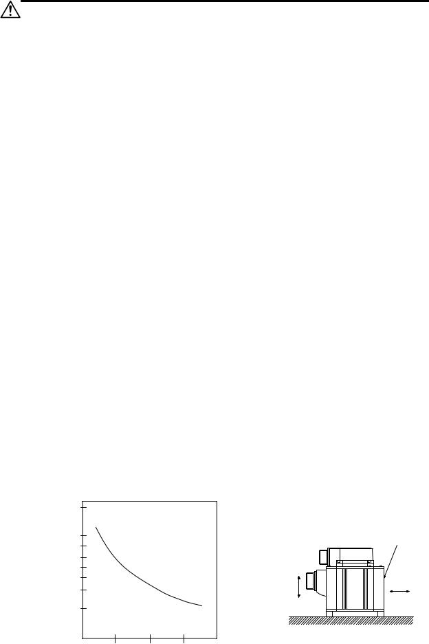
1-1-2 Quakeproof level |
|
|
|
|
||||
|
|
|
|
|
|
|
|
|
|
|
Motor type |
|
Acceleration direction |
||||
|
|
|
Axis direction (X) |
Direction at right angle to axis (Y) |
||||
|
|
|
|
|
|
|||
|
|
|
|
|
|
|||
|
|
HC52 to HC152, HC53 to HC153 |
|
9.8m/s2 (1G) or less |
24.5m/s2 (2.5G) or less |
|||
|
|
HC103R to HC503R, HA053N to HA33N |
|
|
|
|
||
|
|
HC202, HC352, HC203, HC353 |
|
19.6m/s2 (2G) or less |
49.0m/s2 (5G) or less |
|||
|
|
HC452, HC702, HC453, HC703 |
|
11.7m/s2 (1.2G) or less |
29.4m/s2 (3G) or less |
|||
|
|
HA-LF11K2-S8, HA-LF15K2-S8 |
|
|
|
|
||
|
|
HC902 |
|
|
|
9.8m/s2 (1G) or less |
24.5m/s2 (2.5G) or less |
|
The vibration conditions are as shown below.
|
200 |
(µm) |
100 |
|
|
Vibrationamplitude sway-(doublewidth) |
80 |
20 |
|
|
60 |
|
50 |
|
40 |
|
30 |
0 |
1000 |
2000 |
3000 |
Speed (r/min)
Servomotor
X |
Y |
Acceleration
1 - 2
1. Installation
1-1-3 Cautions for mounting load (prevention of impact on shaft)
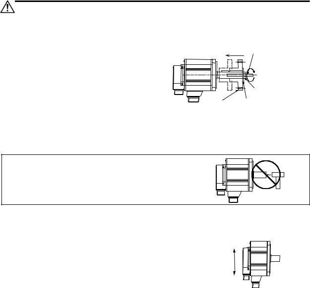
[1]When using the servomotor with key way, use the screw hole at the end of the shaft to mount the pulley onto the shaft. To install, first place the double-end stud into the shaft screw holes, contact the coupling end surface against the washer, and press in as if tightening with a nut. When the shaft does not have a key way, use a frictional coupling, etc.
[2]When removing the pulley, use a pulley remover, and make sure not to apply an impact on the shaft.
Servomotor |
Double-end stud |
Nut
Washer
Pulley
[3]Install a protective cover on the rotary sections such as the pulley installed on the shaft to ensure safety.
[4]The direction of the detector installed on the servomotor cannot be changed.
Never hammer the end of the shaft
CAUTION during assembly.
1-1-4 Installation direction
[1]There are no restrictions on the installation direction. Installation in any direction is possible, but as a standard the motor is installed so that the motor power line and detector cable cannon plugs (lead-in wires) face downward. Installation in the standard direction is effective against dripping. Measure to prevent oil and water must be taken when not installing in the standard direction. When the motor is not installed in the standard direction, refer to section "1-1-6 Oil/water standards" and take the appropriate measures.
The brake plates may make a sliding sound when a servomotor with magnetic brake is installed with the shaft facing upward, but this is not a fault.
Up
Down
Standard installation direction
1 - 3
1. Installation
1-1-5 Shaft characteristics
There is a limit to the load that can be applied on the motor shaft. Make sure that the load applied on the radial direction and thrust direction, when mounted on the machine, is below the tolerable values given below. These loads may affect the motor output torque, so consider them when designing the machine.
Servomotor |
Tolerable radial load |
|
Tolerable thrust load |
|
|
|
|
|
|
HA053NS, HA13NS |
78.4N |
(L=26mm) |
|
49N |
HA23NS, HA33NS |
245N |
(L=30 mm) |
|
147N |
HA23NT, HA33NT |
|
|||
|
|
|
|
|
HC103RT, HC153RT, HC203RT |
392N |
(L=45 mm) |
|
196N |
HC52T, HC102T, HC152T |
392N |
(L=58 mm) |
|
490N |
HC53T, HC103T, HC153T |
|
|||
|
|
|
|
|
HC103RS, HC153RS, HC203RS |
686N |
(L=45 mm) |
|
196N |
HC353RS, HC503RS |
980N |
(L=63 mm) |
|
392N |
HC52S, HC102S, HC152S |
980N |
(L=55 mm) |
|
490N |
HC53S, HC103S, HC153S |
|
|||
|
|
|
|
|
HC202S, HC352S, HC452S, HC702S |
2058N |
(L=79 mm) |
|
980N |
HC203S, HC353S, HC453S, HC703S |
|
|||
|
|
|
|
|
HC902S |
2450N |
(L=85 mm) |
|
980N |
HA-LF11K2-S8 |
|
|||
|
|
|
|
|
HA-LF15K2-S8 |
2940N |
(L=100 mm) |
|
980N |
Note: The symbol L in the table refers to the value of L below.
L
Radial load
Thrust load
L: Length from flange installation surface to center of load weight [mm]
1.Use a flexible coupling when connecting with a ball screw, etc., and keep the shaft core deviation to below the tolerable radial load of the shaft.
2.When directly installing the gear on the motor shaft, the radial load increases as the diameter of the gear decreases. This should be carefully considered when designing the machine.
3.When directly installing the pulley on the motor shaft, carefully consider so
CAUTION |
that the radial load (double the tension) generated from the timing belt tension |
|
is less than the values shown in the table above. |
4.In machines where thrust loads such as a worm gear are applied, carefully consider providing separate bearings, etc., on the machine side so that loads exceeding the tolerable thrust loads are not applied to the motor.
5.Do not use a rigid coupling as an excessive bending load will be applied on the shaft and could cause the shaft to break.
1 - 4
1. Installation
1-1-6 |
Oil/water standards |
|
|
|
|
|
|
|
|
|
|
|
[1] |
The motor protective format uses the IP type, which complies with IEC |
|
|
|
|
|
|
|
Oil or water |
|||
|
Standard. However, these Standards are short-term performance |
|
|
|
|
|
|
|
|
|||
|
specifications. They do not guarantee continuous environmental |
|
|
|
|
|
|
|
|
|||
|
|
|
|
|
|
|
|
|
||||
|
protection characteristics. Measures such as covers, etc., must be |
|
|
|
|
|
|
|
|
|||
|
taken if there is any possibility that oil or water will fall on the motor, |
|
|
|
|
|
|
|
|
|||
|
and the motor will be constantly wet and permeated by water. Note |
|
|
|
|
|
|
|
|
|||
|
|
|
|
|
|
|
|
|
||||
|
|
|
|
|
|
|
|
|
||||
|
that the motor’s IP-type is not indicated as corrosion-resistant. |
|
|
|
|
|
|
|
|
|||
|
|
|
|
|
|
|
|
|
||||
[2] |
When a gear box is installed on the servomotor, make sure that the oil |
|
|
|
|
|
|
Servomotor |
||||
|
|
|
|
|
|
|
|
|||||
|
level height from the center of the shaft is higher than the values given below. Open a breathing |
|||||||||||
|
hole on the gear box so that the inner pressure does not rise. |
|
|
|
|
|
|
|
|
|||
|
|
|
|
|
|
|
|
|
|
|
|
|
|
|
Servomotor |
Oil level (mm) |
|
|
|
|
|
|
|
|
|
|
|
|
|
|
|
|
|
|
|
|
|
|
|
|
HA053N, HA13N |
8 |
|
|
|
|
|
|
|
|
|
|
|
HA23N, HA33N |
10 |
|
|
Gear |
||||||
|
|
HC52, HC102, HC152 |
|
|
|
|||||||
|
|
|
|
|
|
|
|
|
|
|
|
|
|
|
HC53, HC103, HC153 |
20 |
|
|
|
|
|
|
|
|
Servomotor |
|
|
HC103R, HC153R, HC203R |
|
|
|
|
|
|
|
|
|
|
|
|
|
Oil level |
|
|
|
|
|
|
|
|
|
|
|
HC353R, HC503R |
|
|
|
|
|
|
|
|
|
|
|
|
HC202, HC352, HC452, HC702 |
25 |
|
|
|
|
|
|
|
|
|
|
|
|
|
Lip |
||||||||
|
|
HC203, HC353, HC453, HC703 |
|
|
||||||||
|
|
|
|
|
||||||||
|
|
|
|
|
|
|
|
V-ring |
||||
|
|
HC902 |
30 |
|
||||||||
|
|
|
|
|
|
|
|
|
|
|
||
|
|
HA-LF11K2-S8 |
34 |
|
|
|
|
|
|
|
|
|
|
|
HA-LF15K2-S8 |
48 |
|
|
|
|
|
|
|
|
|
[3]When installing the servomotor horizontally, set the power cable and detector cable to face downward. When installing vertically or on an inclination, provide a cable trap.
Cable trap
1. |
The servomotors, including those having IP65 specifications, do not have a |
|
completely waterproof (oil-proof) structure. Do not allow oil or water to |
|
constantly contact the motor, enter the motor, or accumulate on the motor. Oil |
CAUTION 2. |
can also enter the motor through cutting chip accumulation, so be careful of |
When the motor is installed facing upwards, take measures on the machine |
|
|
this also. |
|
side so that gear oil, etc., does not flow onto the motor shaft. |
3. |
Do not remove the detector from the motor. (The detector installation screw is |
|
treated for sealing.) |
1 - 5
1. Installation
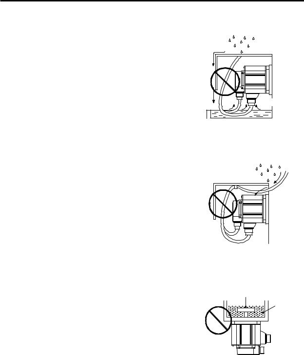
[4]Do not use the unit with the cable submerged in oil or water.
(Refer to right drawing.)
Cover |
Servomotor |
Oil water
<Fault> Capillary tube phenomenon
[5]Make sure that oil and water do not flow along the cable into the motor or detector. (Refer to right drawing.)
[6]When installing on the top of the shaft end, make sure that oil from the gear box, etc., does not enter the servomotor. The servomotor does not have a waterproof structure.
Cover
Servomotor
<Fault> Respiration
Gear
Lubricating oil
Servomotor
1 - 6
1. Installation
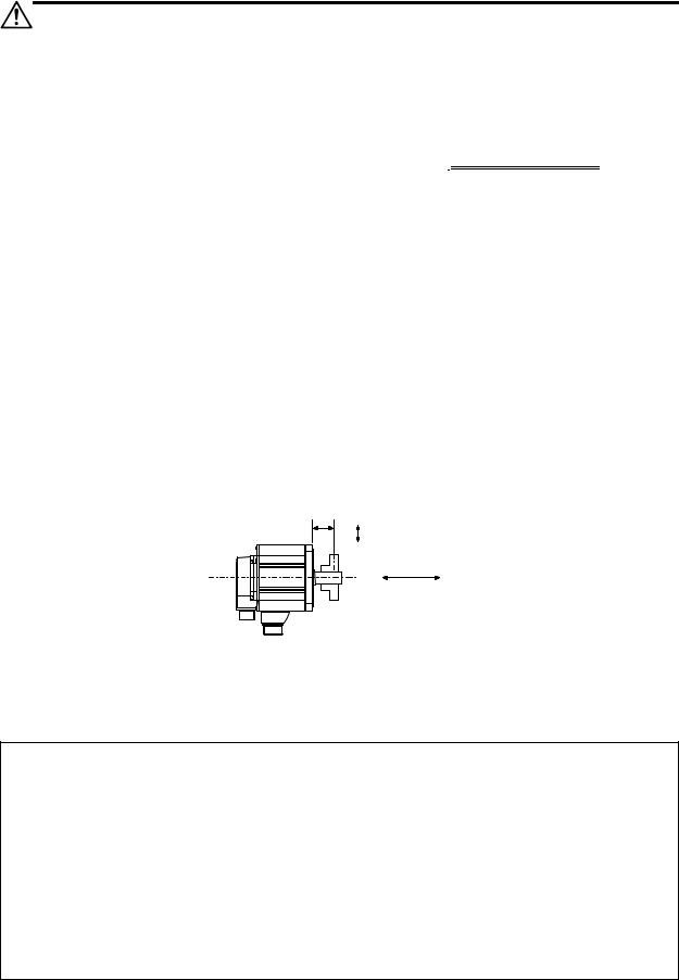
1-1-7 Cable stress
[1]Sufficiently consider the cable clamping method so that bending stress and the stress from the cable's own weight is not applied on the cable connection part.
[2]In applications where the servomotor moves, make sure that excessive stress is not applied on the cable.
If the detector cable and servomotor wiring are stored in a cable bear and the servomotor moves, make sure that the cable bending part is within the range of the optional detector cable.
Fix the detector cable and power cable enclosed with the servomotor.
[3]Make sure that the cable sheathes will not be cut by sharp cutting chips, worn by contacting the machine corners, or stepped on by workers or vehicles.
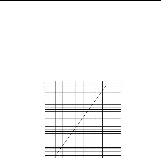
The bending life of the detector cable is as shown below. Regard this with a slight allowance. If the servomotor/spindle motor is installed on a machine that moves, make the bending radius as large as possible.
No. of bends (times)
1×x 1088 |
|
|
|
|
× 77 |
|
|
|
|
5 x 10 |
|
|
|
|
2×10x 77 |
|
|
|
|
1×x 1077 |
|
|
|
|
× 66 |
|
|
|
|
5 x 10 |
|
|
|
|
2×x 1066 |
|
|
|
|
1×10x 66 |
|
|
|
|
5×x 1055 |
|
|
|
|
2×x 1055 |
|
|
|
|
1×x 1055 |
|
|
|
|
5×x 1044 |
|
|
|
|
3×x 1044 |
4 |
7 10 |
20 |
40 70 100 200 |
Bending radius (mm)
Detector cable bending life
(Material of Mitsubishi optional detector cable: A14B2343)
(Note) The values in this graph are calculated values and are not guaranteed.
1 - 7

1. Installation
1-2 Installation of spindle motor
|
|
|
1. Do not hold the cables, axis or detector when transporting the motor. Failure to |
|||
|
|
|
|
observe this could lead to faults or injuries. |
||
|
|
|
2. Securely fix the motor to the machine. Insufficient fixing could lead to the |
|||
|
|
|
|
motor deviating during operation. Failure to observe this could lead to |
||
|
|
|
|
injuries. |
||
|
CAUTION |
3. When coupling to a servomotor shaft end, do not apply an impact by |
||||
|
|
hammering, etc. The detector could be damaged. |
||||
|
|
|
4. Never touch the rotary sections of the motor during operations. Install a |
|||
|
|
|
|
cover, etc., on the shaft. |
||
|
|
|
5. Do not apply a load exceeding the tolerable load onto the servomotor shaft. |
|||
|
|
|
|
The shaft could break. Failure to observe this could lead to injuries. |
||
|
|
|
6. Do not connect or disconnect any of the connectors while the power is ON. |
|||
|
|
|
|
|
||
1-2-1 Environmental conditions |
||||||
|
|
|
|
|
|
|
|
|
Environment |
|
Conditions |
|
|
|
|
|
|
|
|
|
|
|
Ambient temperature |
|
0°C to +40°C (with no freezing) |
|
|
|
|
Ambient humidity |
|
|
90%RH or less (with no dew condensation) |
|
|
|
Storage temperature |
|
-20°C to +65°C (with no freezing) |
|
|
|
|
Storage humidity |
|
|
90%RH or less (with no dew condensation) |
|
|
|
Atmosphere |
|
|
Indoors (Where unit is not subject to direct sunlight) |
|
|
|
|
|
No corrosive gases, flammable gases, oil mist or dust |
|
|
|
|
|
|
|
|
|
|
|
Altitude |
|
|
Operation/storage: 1000m or less above sea level |
|
|
|
|
|
Transportation: 10000m or less above sea level |
|
|
|
|
|
|
|
|
|
(Note) Refer to each spindle motor specifications for details on the spindle motor vibration conditions.
1 - 8
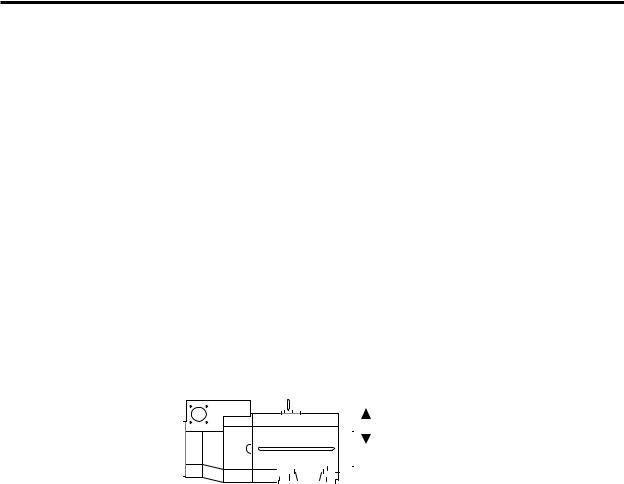
1. Installation
1-2-2 Shaft characteristics
There is a limit to the load that can be applied on the motor shaft. Make sure that the load applied on the radial direction, when mounted on the machine, is below the tolerable values given below. These loads also affect the motor output torque, so consider them when designing the machine.
|
|
|
Spindle motor |
|
|
|
|
|
Tolerable radial load |
|||||||||||||||||||||
|
|
|
|
|
|
|
|
|
|
|
|
|
|
|
|
|
|
|
|
|
|
|
|
|
|
|
|
|
|
|
SJ-V3.7-02ZM |
|
|
|
|
|
490 N |
||||||||||||||||||||||||
SJ-V2.2-01, SJ-V3.7-01 |
|
|
|
|
|
980 N |
||||||||||||||||||||||||
SJ-V7.5-03ZM, SJ-V11-06ZM |
|
|
|
|
|
|||||||||||||||||||||||||
|
|
|
|
|
|
|||||||||||||||||||||||||
SJ-V5.5-01, SJ-V11-08ZM |
|
|
|
|
|
1470 N |
||||||||||||||||||||||||
SJ-PMF01830-00 |
|
|
|
|
|
|||||||||||||||||||||||||
|
|
|
|
|
|
|||||||||||||||||||||||||
SJ-V7.5-01, SJ-V11-01 |
|
|
|
|
|
1960 N |
||||||||||||||||||||||||
SJ-V22-06ZM, SJ-V30-02ZM, SJ-PMF03530-00 |
|
|
|
|
|
|||||||||||||||||||||||||
|
|
|
|
|
|
|||||||||||||||||||||||||
SJ-V11-09, SJ-V15-01, SJ-V15-03, SJ-V18.5-01, SJ-V18.5-03 |
|
|
|
|
|
2940 N |
||||||||||||||||||||||||
SJ-V22-01, SJ-V22-05, SJ-V26-01, SJ-30A |
|
|
|
|
|
|||||||||||||||||||||||||
|
|
|
|
|
|
|||||||||||||||||||||||||
SJ-22XW5 |
|
|
|
|
|
3920 N |
||||||||||||||||||||||||
SJ-37BP |
|
|
|
|
|
4900 N |
||||||||||||||||||||||||
SJ-22XW8, SJ-45BP |
|
|
|
|
|
5880 N |
||||||||||||||||||||||||
SJ-V55-01 |
|
|
|
|
|
|||||||||||||||||||||||||
|
|
|
|
|
|
|||||||||||||||||||||||||
|
|
|
|
|
|
|
|
|
|
|
|
|
|
|
|
|
|
|
|
|
|
|
|
|
|
|
|
|
Radial load |
|
|
|
|
|
|
|
|
|
|
|
|
|
|
|
|
|
|
|
|
|
|
|
|
|
|
|
|
|
|
||
|
|
|
|
|
|
|
|
|
|
|
|
|
|
|
|
|
|
|
|
|
|
|
|
|
|
|
|
|
||
|
|
|
|
|
|
|
|
|
|
|
|
|
|
|
|
|
|
|
|
|
|
|
|
|
|
|
|
|
||
(Note) The load point is at the one-half of the shaft length.
1 - 9

|
|
1. Installation |
1-3 Installation of the control unit |
||
|
|
|
1. |
Install the unit on noncombustible material. Direct installation on |
|
|
|
combustible material or near combustible materials may lead to fires. |
2. |
Follow the instructions in this manual and install the unit while allowing for |
|
|
|
the unit weight. |
3. |
Do not get on top of the units or motor, or place heavy objects on the unit. |
|
|
|
Failure to observe this could lead to injuries. |
4. |
Always use the unit within the designated environment conditions. |
|
5. |
Do not let conductive objects such as screws or metal chips, etc., or |
|
|
CAUTION 6. |
combustible materials such as oil enter the units. |
|
Do not block the units intake and outtake ports. Doing so could lead to |
|
|
|
failure. |
7. |
The units and servomotor are precision devices, so do not drop them or apply |
|
|
|
strong impacts to them. |
8. |
Do not install or run units or servomotor that is damaged or missing parts. |
|
9. |
When storing for a long time, please contact your dealer. |
|
10.Always observe the installation directions. Failure to observe this could lead to faults.
11.Secure the specified distance between the units and panel, or between the units and other devices. Failure to observe this could lead to faults.
1-3-1 Environmental conditions
Environment |
Conditions |
|
|
|
|
Ambient temperature |
0°C to +55°C (with no freezing) |
|
Ambient humidity |
90%RH or less (with no dew condensation) |
|
Storage temperature |
-15°C to +70°C (with no freezing) |
|
Storage humidity |
90%RH or less (with no dew condensation) |
|
Atmosphere |
Indoors (no direct sunlight); |
|
no corrosive gases, inflammable gases, oil mist, dust or conductive particles |
||
|
||
Altitude |
Operation/storage: 1000m or less above sea level |
|
Transportation: 10000m or less above sea level |
||
|
||
Vibration |
Operation/storage: 4.9m/s2 (0.5G) or less |
|
Transportation: 49m/s2 (5G) or less |
(Note) When installing the machine at 1,000m or more above sea level, the heat dissipation characteristics will drop as the altitude increases. The upper limit of the ambient temperature drops 1°C with every 100m increase in altitude. (The ambient temperature at an altitude of 2,000m is between 0 and 45°C.)
1 - 10

1. Installation
1-3-2 Installation direction and clearance
Wire each unit in consideration of the maintainability and the heat dissipation, as well as secure sufficient space for ventilation.
100mm or more
10mm 


 or
or  more
more 
100mm or more
|
|
75mm or more |
|
100mm or |
100mm or |
|
more |
more |
10mm |
|
|
or |
|
|
more |
50mm |
50mm |
|
||
|
or more |
|
|
or more |
|
|
|
|
|
100mm or |
100mm or |
|
more |
more |
The ambient temperature condition for the power supply unit or the drive units is
55°C or less. Because heat can easily accumulate in the upper portion of the
CAUTION units, give sufficient consideration to heat dissipation when designing the panel. If required, install a fan in the panel to agitate the heat in the upper portion of the
units.
1-3-3 Prevention of entering of foreign matter
Treat the cabinet with the following items.
• Make sure that the cable inlet is dust and oil proof by using packing, etc.
• Make sure that the external air does not enter inside by using head radiating holes, etc.
•Close all clearances.
•Securely install door packing.
•If there is a rear cover, always apply packing.
•Oil will tend to accumulate on the top. Take special measures such as oil-proofing to the top so that oil does not enter the cabinet from the screw holds.
•After installing each unit, avoid machining in the periphery. If cutting chips, etc., stick onto the electronic parts, trouble may occur.
•When using the unit in an area with toxic gases or high levels of dust, protect the unit with air purging (system to blow clean air so that the panel's inner pressure is higher than the outer pressure).
1 - 11
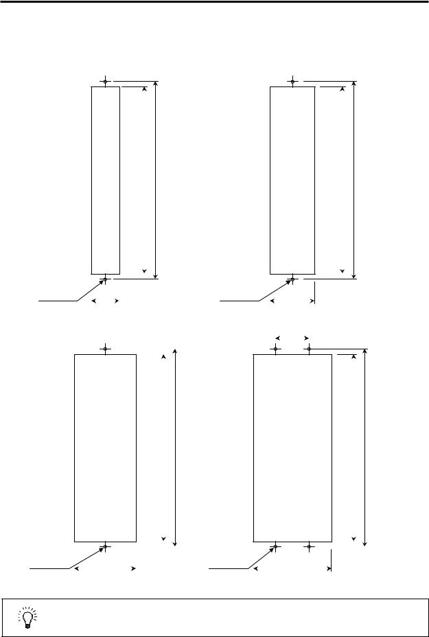
1. Installation
1-3-4 Panel installation hole work drawings (Panel cut drawings)
Prepare a square hole to match the unit width.
[Unit: mm]
Square hole (Note 1)
342 |
360 |
|
|
|
|
|
|
|
Square hole (Note 1)
342 |
360 |
|
|
|
|
|
|
|
2-M5 screw |
52 |
|
2-M5 screw |
82 |
||
|
|
|
|
|
|
|
Unit width: 60mm (only with fin) |
|
Unit width: 90mm |
||||||
|
|
|
|
|
|
|||
|
|
|
|
60 |
|
|
||
|
|
|
|
|
|
|
|
|
|
|
|
|
|
|
|
|
|
|
|
|
|
|
|
|
|
|
Square hole (Note 1)
|
342 |
360 |
|
|
|
|
|
|
|
|
|
|
|
|
|
Square hole (Note 1)
|
342 |
360 |
|
|
|
|
|
|
|
|
|
|
|
|
|
2-M5 screw |
|
112 |
|
4-M5 screw |
|
142 |
|
|
Unit width: 120mm |
|
|
Unit width: 150mm |
|
1. Attach packing around the square hole to provide a seal.
POINT 2. A square hole does not need to be machined on the MDS-C1-V1-10 or smaller, MDS-C1-V2-1010 or smaller and MDS-C1-SP-15 or smaller units.
1 - 12

1. Installation
1-3-5 Heating value
Each heating value is calculated with the following values.
The values for the servo drive unit are for a stall output, and the values for the spindle drive unit are for a continuous rated output. The value for the power supply unit includes the AC reactor's heating value.
Servo drive unit
|
Heating amount |
||
Type |
|
[W] |
|
MDS-C1- |
Inside |
|
Outside |
|
|
||
|
panel |
|
panel |
|
|
|
|
V101 |
21 |
|
0 |
V103 |
27 |
|
0 |
V105 |
37 |
|
0 |
V110 |
53 |
|
0 |
V120 |
25 |
|
66 |
V135 |
30 |
|
102 |
V145S |
34 |
|
124 |
V145 |
37 |
|
148 |
V170S |
38 |
|
151 |
V170 |
50 |
|
234 |
V190 |
56 |
|
275 |
V1-110 |
74 |
|
392 |
V1-150 |
96 |
|
545 |
|
|
|
|
|
|
|
|
|
|
|
|
|
|
|
|
|
|
|
|
|
|
|
|
|
|
|
|
|
|
|
|
|
|
|
|
|
|
|
|
|
|
|
|
|
Heating amount |
||
Type |
|
[W] |
|
MDS-C1- |
Inside |
|
Outside |
|
|
||
|
panel |
|
panel |
|
|
|
|
V2-0101 |
38 |
|
0 |
V2-0301 |
41 |
|
0 |
V2-0303 |
43 |
|
0 |
V2-0501 |
46 |
|
0 |
V2-0503 |
52 |
|
0 |
V2-0505 |
62 |
|
0 |
V2-1005 |
78 |
|
0 |
V2-1010 |
96 |
|
0 |
V2-2010 |
37 |
|
117 |
V2-2020 |
41 |
|
137 |
V2-3510S |
44 |
|
146 |
V2-3510 |
42 |
|
148 |
V2-3520S |
48 |
|
165 |
V2-3520 |
45 |
|
168 |
V2-3535 |
51 |
|
209 |
V2-4520 |
52 |
|
214 |
V2-4535 |
57 |
|
249 |
V2-4545S |
55 |
|
225 |
V2-4545 |
64 |
|
295 |
V2-7035 |
70 |
|
336 |
V2-7045 |
77 |
|
382 |
V2-7070S |
65 |
|
300 |
V2-7070 |
90 |
|
468 |
V2-9090S |
65 |
|
300 |
|
|
|
|
Spindle drive unit |
Power supply unit |
||||||
|
Heating amount |
|
Heating amount |
||||
Type |
|
[W] |
Type |
|
[W] |
||
MDS-C1- |
Inside |
|
Outside |
MDS-C1- |
Inside |
|
Outside |
|
panel |
|
panel |
|
panel |
|
panel |
|
|
|
|
|
|
||
SP04 |
30 |
|
0 |
CV37 |
21 |
|
34 |
SP075 |
40 |
|
0 |
CV55 |
23 |
|
42 |
SP15 |
49 |
|
0 |
CV75 |
25 |
|
55 |
SP22 |
26 |
|
42 |
CV-110 |
26 |
|
99 |
SP37 |
28 |
|
51 |
CV-150 |
29 |
|
126 |
SP55 |
31 |
|
76 |
CV-185 |
33 |
|
162 |
SP75 |
35 |
|
102 |
CV-220 |
35 |
|
175 |
SP-110 |
41 |
|
140 |
CV-260 |
40 |
|
220 |
SP-150S |
48 |
|
140 |
CV-300 |
46 |
|
274 |
SP-150 |
48 |
|
187 |
CV-370 |
54 |
|
346 |
SP-185 |
62 |
|
280 |
|
|
|
|
SP-220 |
65 |
|
301 |
|
|
|
|
SP-260 |
80 |
|
403 |
|
|
|
|
SP-300 |
98 |
|
522 |
|
|
|
|
|
|
|
|
|
|
|
|
|
|
|
|
|
|
|
|
|
|
|
|
|
|
|
|
|
|
|
|
|
|
|
|
|
|
|
|
|
|
|
|
|
|
|
|
|
|
|
|
|
|
|
|
|
|
|
|
|
|
|
|
|
|
|
|
|
|
|
|
|
|
|
|
|
|
|
|
|
|
|
|
Design the panel's heating value taking the actual axis operation (load rate) into
consideration. With a general machine tool, the servo drive unit's load rate is POINT approx. 50%, so the heating values inside the panel are half the values shown
above. (Excluding the power supply and spindle drive unit.)
(Example 1)
When using MDS-C1-CV-260, MDS-C1-SP[]-185 and MDS-C1-V2-3535
Total heating value |
= (40 + 220) + (62 + 280) + (51 + 209) = 862 [W] |
Heating value in panel = (40) + (62) + (51 × 0.5) = 127.5 [W]
1 - 13
1. Installation
1-3-6 Heat radiation countermeasures
In order to secure reliability and life, design the temperature in the panel so that the ambient temperature of each unit is 55°C or less.
If heat accumulates at the top of the unit, etc., install a fan so that the temperature in the panel remains constant.
(Note) Due to the structure, heat easily accumulates at the top of the unit. Install a fan in the power distribution panel to circulate the heat at the top of the unit.
(Inside panel)
Wind speed 2m/s or more
Fan
1 - 14
Loading...