


 Loading...
Air-conditioner Network System |
|
|
|
Centralized Controller |
|
||
Model: AG-150A |
Instruction Book |
||
|
(Web browser for Initial Settings) |
||
Contents |
|
|
|
1 |
Introduction .......................................................................... |
|
1 |
|
1-1 Terms Used in This Manual .................................................... |
1 |
|
|
1-2 Computer Requirements ......................................................... |
|
1 |
|
1-3 Notes on using AG-150A with the integrated centralized control |
||
|
software (TG-2000A)................................................................ |
|
1 |
2 |
Setting the Operating Environment ...................................... |
2 |
|
|
2-1 Setting the PC IP Address....................................................... |
|
2 |
|
2-2 Setting the Web Browser......................................................... |
|
4 |
3 |
Performing Operations ......................................................... |
|
6 |
|
3-1 Logging in on the AG-150A ..................................................... |
6 |
|
4 |
Initial Settings....................................................................... |
|
9 |
|
4-1 Setting the Current Date and Time.......................................... |
9 |
|
|
4-2 Setting the Basic Information and External Input Functions . 10 |
||
|
4-3 Group Setting ........................................................................ |
|
18 |
|
4-4 Interlocked Setting................................................................. |
|
20 |
|
4-5 Block Setting.......................................................................... |
|
21 |
5 |
Functions 1......................................................................... |
|
22 |
|
5-1 Error mail reports/E-mail communication .............................. |
22 |
|
|
5-2 Energy-Save Control and Peak Cut Control ......................... |
25 |
|
|
5-3 Settings for measurement ..................................................... |
|
30 |
6 |
Functions 2......................................................................... |
|
34 |
|
6-1 Limiting the Set Temperature Operating Range ................... |
34 |
|
|
6-2 Night Mode (Silent Mode) Schedule...................................... |
35 |
|
|
6-3 System-Changeover of Y series............................................ |
36 |
|
7 |
Functions 3......................................................................... |
|
37 |
|
7-1 External Temperature Interlock ............................................. |
37 |
|
|
7-2 Night setback control............................................................. |
|
38 |
|
7-3 Interlock control ..................................................................... |
|
39 |
8 |
User Setting ....................................................................... |
|
42 |
9 |
Registering a License for Optional Function ...................... |
44 |
|
Before using the controller, please read this Instruction Book carefully to ensure correct operation. Retain this manual for future reference.
1 Introduction
Special features of Mitsubishi Electric Corporation’s “Centralized Controller AG-150A” is that a PC connected to a LAN can be used to monitor the operation condition of air conditioners, perform air conditioner operations, and make initial settings.
This document explains the procedures for making initial settings for the Centralized Controller AG-150A using the web browser.
Hereinafter, the centralized controller AG-150A, unless otherwise specified, will be called "AG-150A".
Note: License of "Web Monitor" or "Basic License Pack" is necessary to use the web browser and update program. Register the license key on the AG-150A LCD screen.
A one-day license key can be registered on the LCD screen that allows the user to use the "Web Monitor" only on the day of the registration. Use this license key to update the program or to use the initial setting browser, or in any other situations when a temporary license key is necessary.
Note: Use a security device such as a VPN router when connecting the AG-150A to the Internet to prevent unauthorized access. Note: "Booster unit" and "Water HEX unit" are referred to as "Air to water".
1-1 Terms Used in This Manual
-“Click” refers to the action of positioning the mouse cursor on the object (such as button or folder), pressing down, and releasing the left mouse button once.
-Unless otherwise specified, the example screen images used in this manual are Windows XP® and Internet Explorer 6.0 screen images.
Note: Windows is a registered trademark or trademark of Microsoft Corporation USA in the United States and other countries.
-The K transmission converter (PAC-SC25KAA) and OA processing unit (LOSSNAY) are not included in systems shipped to North America (USA & Canada).
1-2 Computer Requirements
To monitor and operate air conditioners by web browser, computer must include the following requirements.
|
Table 1-1 Computer Requirements |
|
Item |
|
Requirement |
CPU |
|
Pentium 300MHz or faster |
Memory |
|
64M Bytes or more (128M Bytes or more recommended) |
Screen resolution |
|
1024 x 768 or higher recommended |
|
|
Microsoft® Internet Explorer 6.0 or later |
|
|
Note: You must have a Java execution environment |
Compatible browser |
|
(Sun Microsystems Java® Plug-in Ver.1.6.0.02 or later). |
|
|
Note: You can check the Sun Microsystems® Java Plug-in version in |
|
|
“Java” in a control panel. |
On-board LAN port or LAN card |
|
One connector (100BASE-TX) |
Other |
|
Pointing device such as a mouse |
Note: Microsoft is a registered trademark or trademark of Microsoft Corporation USA in the United States and other countries.
Sun Microsystems and Java are trademarks or registered trademarks of Sun Microsystems Inc. in the United States and/or other
countries.
1-3 Notes on using AG-150A with the integrated centralized control software (TG-2000A)
If the system is connected to the integrated centralized control software (referred to as TG-2000A hereafter), make all settings and changes from the TG-2000A so that the data in TG-2000A and AG-150A will match.
1
2 Setting the Operating Environment
PC settings and web browser settings required for using a web browser to monitor air conditioner units and perform operations are explained in the following pages.
2-1 Setting the PC IP Address
Set an IP address on the PC that enables AG-150A to connect via a web browser. For instance, if the AG-150A IP address is [192.168.1.1], the PC IP address will need to belong to the same system [192.168.1.101].
If the AG-150A is connected to an existing LAN, ask the LAN administrator to decide what PC IP address to use.
Note: When using a AG-150A dedicated LAN, it is recommended that the AG-150A main unit be given an IP address within the range [192.168.1.1] - [192.168.1.40] and the PCs that will be connected to the AG-150A be given an IP address within the range [192.168.1.101] - [192.168.1.150]
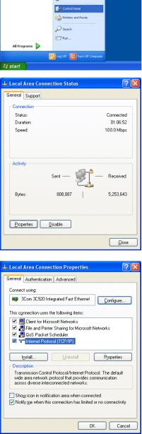
(1)Click on [Control Panel] under [Start] to open the Control Panel.
(2)In the Control Panel window, double click [Network and Dial-up Connections] and the Network and Dial-up Connections window will open. Double click on [Local Area Setting] and the [Local Area Connection Status] dialog will open. Click [Properties].
(3) In the [Local Area Connection Properties] dialog, click [Internet Protocol] to select it and click the [Properties] button.
2
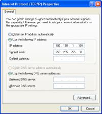
(4) In the [Internet Protocol (TCP/IP) Properties] dialog, click [Use the following IP address] and enter the IP address (for example, “192.168.1.101”) that you want to set in the IP address field.
You normally set [255.255.255.0] as the subnet mask.
Note: Ask your LAN administrator to provide the IP addresses and subnet mask.
(5)Click the [OK] button to close this dialog, and then close the other open dialogs to complete the network setting.
3

2-2 Setting the Web Browser
Use a security device such as a VPN router when connecting the AG-150A to the Internet to prevent unauthorized access.
If no security devices are installed, the operation settings may be changed by an unauthorized person without the knowledge of the user.
Necessary web browser settings must be performed to enable the web browser to connect to the AG-150A.
Note: The settings and screen images used as examples in this manual are based on Internet Explorer 6.0.
2-2-1 No Internet Connection
Follow the instructions below to make the web browser environment settings when using the PC with no Internet connection for monitoring and operating the air conditioners.
(1)Click the web browser menu item [Tools] and then click [Internet Options…] to select.
(2)In the [Internet Options] tabbed dialog, click the [Connections] tab to display.
(3)Select [Never dial a connection] in the Dial-up settings section and click the [OK] button to close the dialog.
2-2-2 Internet Connection Using a Dial-Up
If the PC used for monitoring air conditioners and performing operations is going to connect to the Internet via a dial-up connection, use the procedure given below to set the web browser environment settings.
By performing these settings, a message will appear asking whether or not to use a dial-up connection when an Internet connection is necessary. When connecting to the Internet, follow the directions below.
(1)Click the web browser menu item [Tools] and then click [Internet Options…] to select.
(2)In the [Internet Options] tabbed dialog, click the [Connections] tab to display.
(3)Select [Dial whenever a network connection is not present] in the Dial-up settings section and click the [OK] button to close the dialog.
4
2-2-3 Connecting to the Internet using a proxy server (Using an existing LAN)
If the PC you use for monitoring air conditioners and performing operations is going to access the Internet via proxy server by connecting to an existing LAN such as a LAN within your company, use the procedure given below to set the web browser environment settings.
By performing these settings, your PC will connect to a proxy server only when connecting to the Internet.
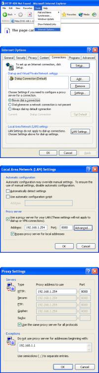
(1)Click the web browser menu item [Tools] and then click [Internet Options…] to select.
(2)In the [Internet Options] tabbed dialog, click the [Connections] tab to display.
(3)Select [Never dial a connection] in the Dial-up setting section.
(4)Click the [LAN Setting . . .] button in the Local Area Network (LAN) settings section to display the Local Area Network (LAN) Settings dialog.
(5)In the Local Area Network (LAN) Settings dialog, check [Bypass proxy server for local addresses] and click the [Advanced...] button.
(6) Enter the IP address for the AG-150A (e.g. 192.168.1.1) in the Exceptions field of the Proxy Setting dialog and click the [OK] button to close the dialog and then close the other open dialogs to complete the setting.
Note: If connecting to more than one AG-150A, you can specify multiple IP addresses like [192.168.1.1; 192.168.1.2], however, it is also possible to use the asterisk (*) and specify [192.168.1.*].
5
3 Performing Operations
Text below explains how to connect to the AG-150A and how to make various settings for the AG-150A.
Note: If the AG-150A is restarted due to a power interruption etc., wait until the screen on the AG-150A main unit displays the normal operation screen (it takes several minutes before the normal operation screen is displayed) before using a web browser to access the AG-150A. If access is attempted while the AG-150A is still starting up, the most recent data might not be displayed or communication errors could occur.
Note: Default IP address of AG-150A is "192.168.1.1". (Factory setting)
3-1 Logging in on the AG-150A
3-1-1 Logging in on the AG-150A
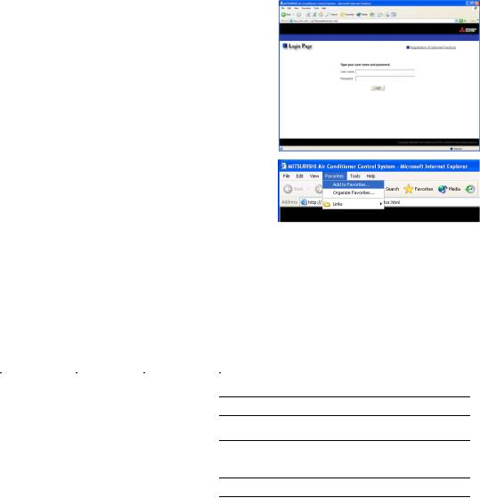
(1) Enter the web page address in the address field of the web browser as follows:
http:// [IP address of the AG-150A]/g-50 /administrator.html
Press the [Enter] key on the keyboard. A screen appears for login.
Note: For example, type “http://192.168.1.1/g-50/administrator.html” if the AG-150A IP address is [192.168.1.1].
(2)To make connection easier for the next time, click the web browser menu item [Favorites], click [Add to Favorites], then add the address to the Favorites folder. Once this address is added to the Favorites folder, it is not necessary to input the address of (1). Simply select it from the Favorites folder and the AG-150A page will appear.
(3)Enter the user name and the password in the login screen, and click the [Login] button. A screen will appear in which various setting are made. An explanation on how to perform operations begins from the next page.
The table below shows the default user names and passwords for maintenance users and building managers as well as available functions.
User |
Default |
Default |
|
Available functions |
|
user name |
password |
|
|||
|
|
|
|||
|
|
|
Initial settings |
Date and Time, Basic System, Groups, Interlocked |
|
|
|
|
|
LOSSNAY, Blocks |
|
|
|
|
Functions 1 |
E-Mail, Peak cut, Measurement |
|
Maintenance |
|
|
|
Set Temperature Range Limit, Night Mode |
|
initial |
init |
Functions 2 |
|||
Schedule, System-changeover |
|||||
user |
|
||||
|
|
|
Interlock control based on outside temperature, |
||
|
|
|
|
||
|
|
|
Functions 3 |
Setback control |
|
|
|
|
|
Interlock control |
|
|
|
|
User Settings |
User Settings |
|
|
|
|
|
|
|
Building |
administrator |
admin |
Out of the functions listed above, the items to which access rights |
||
manager |
have been given on the user settings screen are available. |
||||
|
|
||||
Note: The user name and the password for building manager are the same as those of the building manager of the Web for monitoring/operation.
Note: Maintenance users can make available to the administrator only the information necessary for normal operations (group name setting etc.)
Note: It is recommended to change the user name and password so users other than the manager are not permitted to change the settings.
Note: The Web page is displayed in the same language as the computer uses and it is also possible to display the Web page in other languages by entering the following Web page addresses.
English |
:http://[The IP address of AG-150A]/g-50/en/administrator.html |
German |
:http://[The IP address of AG-150A]/g-50/de/administrator.html |
French |
:http://[The IP address of AG-150A]/g-50/fr/administrator.html |
Spanish |
:http://[The IP address of AG-150A]/g-50/es/administrator.html |
Italian |
:http://[The IP address of AG-150A]/g-50/it/administrator.html |
Russian |
:http://[The IP address of AG-150A]/g-50/ru/administrator.html |
Chinese |
:http://[The IP address of AG-150A]/g-50/zh/administrator.html |
Portuguese |
:http://[The IP address of AG-150A]/g-50/pt/administrator.html |
Japanese |
:http://[The IP address of AG-150A]/g-50/ja/administrator.html |
6

3-1-2 Encrypting the communication data and login on the AG-150A
AG-150A can encrypt communication data using HTTPS (SSL).
When connecting the AG-150A to the LAN that can be accessed by the general public, it is recommended that the following settings be made so that the units are monitored and controlled on the encrypted Web page.
Note: Depending on the operating system or the version of Java, HTTPS encrypted messages may not be handled correctly. If this happens, use a HTTP connection to monitor and control the units as noted in the section above.
(1) Go to [Tools]->[Internet Options]->[Advanced], and make the following settings.
Item |
Checkbox setting |
|
|
Use SSL 2.0 |
Uncheck the box. |
|
|
Use SSL 3.0 |
Check the box. |
|
|
Use TLS 1.0 |
Uncheck the box. |
|
|
Do not save encrypted pages to disk |
Check the box. |
|
|
Note: Some of the settings may have different names depending on the Web browser version.
(2)Click on [Java] in the Control Panel, and make the settings for the items under [Security] in the [Advanced] tab.
Item |
Checkbox setting |
|
|
Use SSL 2.0 compatible Client Hello format |
Uncheck the box. |
|
|
Use SSL 3.0 |
Check the box. |
Use TLS 1.0 |
Uncheck the box. |
|
|
Note: Some of the settings may have different names depending on the Java version.
(3)Prefix the Web address with [https], enter the address, and hit the [Enter] (Return) key on the keyboard.
https://[IP Address of the AG-150A]/g-50 /administrator.html
Note: For example, type “https://192.168.1.1/g-50/administrator.html” if the
AG-150A IP address is [192.168.1.1].
If the security alert is disabled as described in the note in the following and the subsequent sections, encrypted date
communication will begin, and the Login screen will appear. If the security alert has not been disabled, take the following procedures.
7

(4)If the security alert has not been disabled, after entering the web address and hitting the Enter (Return) key, a security alert message will alert asking if you want to proceed . This is because the AG-150A uses the
self-authentication system. Click [Yes] and proceed.
Note: Disable the security alert that appears every time the browser is opened, take the following two steps:
1)Register the security certificate and
2)Change the Web browser's option settings
To register the security certificate, click the [View Certificate] button on the security alert window to display the certificate, click on the [Install Certificate] button, and add the certificate to the Trusted Root Certification Authorities store. Just follow the prompts of the Import Wizard.
Go to [Tools]->[Internet Options]->[Advanced], and make the following settings for the Web browser.
Item |
Checkbox setting |
|
|
Warn about invalid site certificates |
Uncheck the box. |
|
|
(5) A Java security alert message will appear after you click [Yes] in step (4) above, click [Yes] again to proceed.
Note: To disable the security alert message that appears every time the browser is opened, check the check box next to [Always trust content from this publisher], and click [Yes]. The browser may need to be restarted to reflect the change.
Note: If the window shown on the right does not appear and connection fails, the certificate needs to be added to the Java certificate list. Click the [View Certificate] button on the screen in step (4) to display the certificate, click on the [Copy to File] on the [Details] page, and save the
certificate in any desired location in the DER format. Open [Java] in the Control Panel, click on the [Certificates] button on the [Security] page to bring up the certificate registration screen. On the screen, select [Secure Site], click on the [Import] button, change the File of type to [All Files], and select the saved certificate. Now the certificate has been added to the Java certificate list.
(6)If a connection is successfully made, the login window will appear. All communication with the AG-150A will be encrypted. The Web addresses for general users and in each language will have the web address in the previous section with "http" changed to "https".
8
4 Initial Settings
4-1 Setting the Current Date and Time
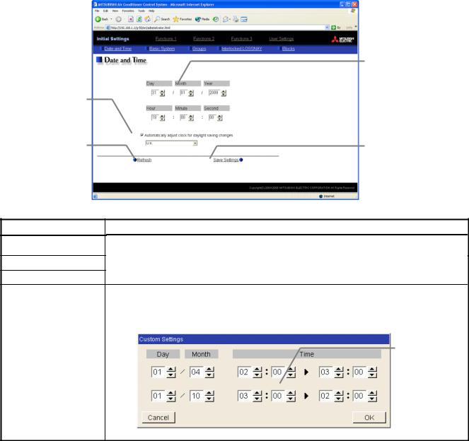
Click [Initial Settings] in the menu, and [Date and Time] screen will appear on the screen. Enter the current date and time, and then press the [Save Settings] button to send the current date and time to AG-150A.
Note: If the user logs in as a building manager, the operations may be prohibited.
Note: If the system is connected to the TG-2000A, make all settings and changes from the TG-2000A so that the data in TG-2000A and AG-150A will match.
Note: When the time setting is made on this screen, the setting will be applied to all the units on M-NET system.
Note: When the DIDO controller (PAC-YG66DCA), AI Controller (PAC-YG63MCA), or PI Controller (PAC-YG60MCA) is newly connected, make the time setting of the connected controller on this screen.
Summer time setting
Click to set the daylight saving time.
Refresh
Acquires the current Date and Time from AG-150A.
Current date/time
Enter the current date and time here.
Save settings
Click to set the current date and time.
Item
Current date/time
Save Settings
Refresh
Summer time setting
Description
Enter the current date and time.
For the date, use the format [day - month - year].
Click the [Date/Time Set] button to set the current date and time. Acquires the current Date and Time from AG-150A.
Click and tick the "Automatically adjust clock for daylight saving changes" box to adjust the daylight saving time automatically, and select the applicable country.
Note: If the applicable country is not in the selection bar, select "Custom Settings". Click "Custom Settings" button that will appear on the right to set the daylight saving time.
Daylight saving date and time
Set the daylight saving time.
Custom Setting Screen
9
4-2 Setting the Basic Information and External Input Functions
Display the page needed to perform the AG-150A basic setting by clicking [Initial Settings]-[Basic System] in the setting menu pane. On this page, you perform the basic setting such as the AG-150A unit name, network setting and M-NET setting. Click [Save Settings] to send setting data to the AG-150A. After the setting data are sent to the AG-150A, a message will appear asking whether or not to restart the AG-150A. Click [OK] to restart the AG-150A to put the changes into effect.
Note: If the user logs in as a building manager, the operations may be prohibited.
Unit Setting
Set the AG-150A name and unit ID.
Network Setting
Set the AG-150A IP address and subnet mask.
Display Format
Set the items related to the screen display on the AG-150A or on the Web.
Refresh
Read setting data from AG-150A.
4-2-1 AG-150A Unit Setting
In Unit Setting, set the AG-150A name and unit ID.
System configuration settings
Set the use or non-use of expansion controller, connection target, M-NET settings, and external input settings.
Use or non-use of expansion
controller
Select from “Do not use” or “Use.”
M-NET Setting
Set the AG-150A M-NET address, presence/absence of K-Control units and range of prohibited controllers.
External Input Setting
Set the AG-150A external input setting.
Save Settings
Send setting data to AG-150A.
(1)Enter the AG-150A unit name in the [Name] field. You may enter a maximum of 40 alphanumeric or symbol characters. The name set here is used on the display screen of the software that controls multiple AG-150A
units and for the name of the sender in the body of error messages.
Note: The following characters cannot be used in the name: < > & " '
(2)Enter the AG-150A unit ID in the [Unit ID] field. You must enter 6 numeric characters. Use this setting when you want to control multiple AG-150A units with unit IDs. The unit ID that is entered here will be used on the display screen of the software that controls multiple AG-150A units and for the sender ID in the body of error messages.
(3)When [Refresh] is clicked, the AG-150A production ID will appear in the [SERIAL No.] field and the AG-150A software version will appear in the [Software Version] field.
10

(3)After the expansion controller connection setting or the IP address of the expansion controller was changed, click the [Save] button and restart the G-150AD by following the messages on the screen. Make the M-NET settings and external input settings after the system has been restarted.
*To change the settings for the external input settings (or any other settings that are saved on the expansion controller side) after the M-NET settings have been made, restart the controller and change the settings with the expansion controller properly being connected to the system.
*After connecting the expansion controller, check that the database number (DB No.) on the controller itself and the data base number of the expansion controller match. If they do not, consult your dealer for software upgrade.
4-2-2-2 M-NET Setting
In M-NET Setting, set the AG-150A M-NET address, whether or not a K-Control unit is present and which machines send the prohibited controller command.
(1)Enter the AG-150A M-NET address in the [M-NET Address] field. Normally you should enter [0].
(2)When K-Control air conditioners are connected, click [Used] in the [K-Control Units] field and enter the M-NET address of K transmission converter in the [K Converter Address] field.
(3)If prohibited controller (prohibiting local operation) has been set, this setting determines the scope of this setting s control, i.e. operation is prohibited for both the remote control and subordinate system controllers, or just for the remote control. Click [SC/RC] when you want prohibited controllers to include both subordinate system controllers and the remote control, or click [RC only] when you only want to prohibit
operation on the remote control.
Note: Normally, you should select [SC/RC].
11

4-2-2-3 External Input Setting
In the External Input Setting menu, set the AG-150A external input function. By using external input functions, it is possible to stop and run multiple air conditioners connected to the AG-150A via the separately sold external I/O adapter for AG-150A (Model: PAC-YG10HA) using level signals and pulse signals.
* If PAC-YG50ECA expansion controllers are connected, expansion controller system selection buttons will appear. Select the desired expansion system controller, and make the settings for each system. Make the settings with the expansion controllers properly connected. Connect the external input signal wires to each controller’s external input terminal.
(1)Select [Not in use] when not using the external input function.
(2)Selecting [Emergency stop (Level signal)] makes it possible to stop multiple units by using a level signal. While this stop operation is being performed, operations such as running or stopping units are prohibited on the AG-150A unit or remote control.
1 |
|
2 |
Emergency stop/normal |
3 |
|
4 |
|
5 |
|
6 |
DC 12V |
7 |
|
8 |
|
9 |
|
Connection to AG-150A (CN5)
Contact ON |
|
|
Contact OFF |
Emergency |
|
Normal |
Stop |
Normal |
(3)Selecting [ON/OFF (Level signal)] makes it possible to run or stop multiple units using a level signal. In this mode, all air conditioner units connected to the AG-150A will be run or stopped and run/stop operations will be prohibited on the AG-150A unit or remote control.
1 |
|
2 |
Run/Stop |
3 |
|
4 |
|
5 |
DC12V |
6 |
|
7 |
|
8 |
|
9 |
|
Connection to AG-150A (CN5)
Contact ON
Contact OFF
Stop |
Run |
Stop |
12

(4) Selecting [ON/OFF/Prohibit/Permit (Pulse signal)] makes it possible to use pulse signals to run multiple units, stop multiple units, prohibit local operation and permit local operation. In this mode, it is possible to freely operate the remote control except during the pulse signal input.
1 |
|
2 |
Run |
3 |
|
4 |
Stop |
5 |
|
6 |
|
7 |
|
8 |
|
9 |
|
Prohibit |
Permit |
|
|
DC12V |
:Pulse generator |
|
|
||
Connection to AG-150A (CN5) |
|
||

 0.5 - 1.0 Seconds
Contact ON
Run
Contact OFF
Contact ON |
|
|
Stop |
|
|
Contact OFF |
Run |
Stop |
Stop |
|
Contact ON |
0.5 - 1.0 Seconds |
|
Prohibit |
|
|
|
Contact OFF |
|
|
|
|
|
|
|
Permit |
Contact ON |
|
|
Contact OFF |
|
|
|
|
|
|
|
|
Permit |
Prohibit |
Permit |
13

4-2-3 Network Setting
In Network Setting, set the AG-150A IP address, subnet mask and gateway address. If connecting to the AG-150A via a permanent LAN, consult with the network administrator before setting these addresses.
14
Loading...