


GROUP 13
FUEL
CONTENTS
MULTIPOINT FUEL INJECTION (MPI). . . . . . . . . . . . . . . . . . . . 13A MULTIPOINT FUEL INJECTION (MPI) <4G1>. . . . . . . . . . . . . . 13B FUEL SUPPLY . . . . . . . . . . . . . . . . . . . . . . . . . . . . . . . . . . . . . . 13C

GROUP 15
INTAKE AND EXHAUST
CONTENTS
AIR INTAKE SYSTEM . . . . . . . . . . . . |
15-2 |
AIR DUCT AND AIR CLEANER . . . . . . . . . |
15-2 |
INTERCOOLER <4G1> . . . . . . . . . . . . . . . |
15-3 |
INLET MANIFOLD <4A9>. . . . . . . . . . . . . . |
15-4 |
INLET MANIFOLD <4G1> . . . . . . . . . . . . . |
15-4 |
EXHAUST SYSTEM . . . . . . . . . . . . . . |
15-5 |
EXHAUST MANIFOLD <4A9> . . . . . . . . . . |
15-5 |
TURBOCHARGER <4G1> . . . . . . . . . . . . . |
15-6 |
EXHAUST PIPE AND MUFFLER <4A9> . . |
15-7 |
EXHAUST PIPE AND MUFFLER <4G1> . . |
15-8 |

15-2 |
INTAKE AND EXHAUST |
|
AIR INTAKE SYSTEM |
AIR INTAKE SYSTEM
AIR DUCT AND AIR CLEANER
M2150004000504
CONSTRUCTION DIAGRAM
<4A9>
Air cleaner resonator
Engine |
Engine |
air intake hose |
air intake hose |
<M/T> |
<CVT> |
Air cleaner assembly
Air cleaner intake duct
AC601193AB
<4G1>
Engine air intake hose
 Air cleaner assembly
Air cleaner intake duct
AC402138AB
•An air cleaner resonator has been adopted to improve engine performance and reduce air intake noise <4A9>.
•A front air intake system that actively sucks cooling air from the front through the top of the radiator has been adopted in order to improve engine performance and reduce air intake noise.
•For the air cleaner intake duct, a venturi duct with a diaphragm on its path has been adopted to suppress rise in air resistance and reduce air intake noise.
•In consideration of industrial waste reduction and global environment, recycled materials made from eating utensils and the scraps have been adopted for the air cleaner body and cover of the air cleaner assembly.

INTAKE AND EXHAUST |
15-3 |
AIR INTAKE SYSTEM |
|
INTERCOOLER <4G1>
M2150007000246
An air cooled intercooler has been adopted to lower the intake air temperature drastically and improve engine performance.
CONSTRUCTION DIAGRAM
Air by-pass valve 
Intercooler assembly
Intercooler inlet air duct
AC600080AB

15-4 |
INTAKE AND EXHAUST |
|
AIR INTAKE SYSTEM |
INLET MANIFOLD <4A9>
M2150010000105
 Inlet port
AK305379AB
The inlet manifold is made of resin. The inlet ports are curled for size and weight reduction.
INLET MANIFOLD <4G1>
M2150010000116
AK403235
The port shape is changed to be optimum for the vehicle with the turbocharger.

INTAKE AND EXHAUST |
15-5 |
EXHAUST SYSTEM |
|
EXHAUST SYSTEM
EXHAUST MANIFOLD <4A9>
M2150006000317
Pipes
AK402037AD
The exhaust manifold consists of stainless steel pipes, with all the ports being equal in length, to achieve robust mid-range torque and weight reduction.
15-6 |
INTAKE AND EXHAUST |
|
EXHAUST SYSTEM |
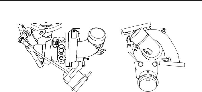
TURBOCHARGER <4G1>
Considering the balance among the engine output, the response and the amount of the exhaust gases, the optimized size is used .
M2150009000123
AK402141

INTAKE AND EXHAUST |
15-7 |
EXHAUST SYSTEM |
|
EXHAUST PIPE AND MUFFLER <4A9>
M2150003000642
CONSTRUCTION DIAGRAM
<M/T> |
Exhaust main muffler |
|
Centre exhaust pipe |
Annular joint
Under floor catalytic converter
Insertion joint
Front exhaust pipe |
Exhaust pre-muffler |
|
AC601362AB
<CVT> |
Exhaust main muffler |
|
Centre exhaust pipe |
Annular joint
Under floor catalytic converter
Insertion joint
Front exhaust pipe |
Exhaust pre-muffler |
AC601363AB
Exhaust pipe consisting of three separation system: front exhaust pipe, centre exhaust pipe, and exhaust main muffler, has the following features:
•An exhaust pre-muffler has been installed to the centre exhaust pipe in order to reduce exhaust noise.
•An insertion joint has been adopted for the connection between the centre exhaust pipe and the exhaust main muffler to save the weight of the exhaust system.
•The under floor catalytic converter has been moved closer to the engine side to improve exhaust gas performance.
•An annular joint has been adopted for the connection between the exhaust manifold and the front exhaust pipe to reduce the exhaust pipe's vibration from the engine side.

15-8 |
INTAKE AND EXHAUST |
|
EXHAUST SYSTEM |
EXHAUST PIPE AND MUFFLER <4G1>
M2150003000653
CONSTRUCTION DIAGRAM
|
|
Exhaust main muffler |
|
|
Centre exhaust pipe |
|
|
Under floor |
Front |
Front exhaust pipe |
catalytic converter |
|
||
catalytic |
|
|
converter |
|
Insertion joint |
|
|
|
|
Annular joint |
Exhaust pre-muffler |
|
|
|
|
|
AC601366AB |
Exhaust pipe consisting of three separation system: front exhaust pipe, centre exhaust pipe, and exhaust main muffler, has the following features:
•An exhaust pre-muffler has been installed to the centre exhaust pipe in order to reduce exhaust noise.
•An insertion joint has been adopted for the connection between the centre exhaust pipe and the exhaust main muffler to save the weight of the exhaust system.
•An annular joint has been adopted for the connection between the front exhaust pipe and the front catalytic converter has been adopted to reduce vibration from the engine side.
•A front catalytic converter and an under floor catalytic converter have been adopted to improve exhaust gas performance.

GROUP 17
ENGINE AND
EMISSION
CONTROL
CONTENTS
ENGINE CONTROL . . . . . . . . . . . . . . |
17-2 |
EMISSION CONTROL . . . . . . . . . . . . |
17-3 |
ACCELERATOR SYSTEM . . . . . . . . . . . . . |
17-2 |
GENERAL INFORMATION <4A9> . . . . . . . |
17-3 |
|
|
GENERAL INFORMATION <4G1> . . . . . . . |
17-4 |
17-2 |
ENGINE AND EMISSION CONTROL |
|
ENGINE CONTROL |
ENGINE CONTROL
ACCELERATOR SYSTEM
M2170003000310
For the accelerator system, an electronic throttle valve control system has been adopted, eliminating of an accelerator cable. This system detects the amount of the accelerator pedal movement by using a accelerator pedal-position sensor in the accelerator pedal assembly for electronic control of the throttle valve angle.
CONSTRUCTION DIAGRAM
Accelerator pedal assembly (Built-in accelerator pedal position sensor)
Accelerator pedal arm stopper
AC206106 AD

ENGINE AND EMISSION CONTROL |
17-3 |
EMISSION CONTROL |
|
EMISSION CONTROL
GENERAL INFORMATION <4A9>
Although the emission control systems are basically the same as those of the 4G1-Non-Turbo engine used in the COLT, the following improvements have been added.
M2171000100838
•The adoption of the catalytic converter just beneath exhaust manifold realizes the earlier activation.
•The adoption of the dual oxygen sensor has increased reliability air/fuel ratio control.
•The abolition of the EGR system <M/T>.
System |
Remarks |
Crank case ventilaton system |
Closed type |
|
|
Evaporative emission control system |
Electronic control type with duty signal |
|
|
Exhaust gas recirculation (EGR) system <CVT> |
Electronic control (stepper motor) type |
|
|
Air/fuel ratio closed loop control |
Oxygen sensor signal used |
|
|
Catalytic converter |
Three-way catalytic converter |
|
|
EMISSION CONTROL SYSTEM DIAGRAM
Oxygen sensor (rear) |
Air |
|
Oxygen sensor (front) |
||
inlet |
|
From |
|
|
fuel pump |
|
PCV valve |
|
|
Injector |
EGR valve |
|
|
(stepper motor) |
Canister |
|
<CVT> |
Purge control solenoid valve
Catalytic converter |
AK402829AC |
|

17-4 |
ENGINE AND EMISSION CONTROL |
|
EMISSION CONTROL |
GENERAL INFORMATION <4G1>
Although the emission control systems are basically the same as those of the 4G1-Non-Turbo engine used in the COLT, the following improvements have been added.
•The adoption of the catalytic converter just beneath turbo charger and under the floor increased the performance of the emission controls.
M2171000100849
•The adoption of the check valve between the purge control solenoid valve and the canister protects the regurgitation as turbocharging.
•The abolition of the EGR system
System |
Remarks |
Crank case ventilaton system |
Closed type |
|
|
Evaporative emission control system |
Electronic control type with duty signal |
|
|
Air/fuel ratio closed loop control |
Oxygen sensor signal used |
|
|
Catalytic converter |
Three-way catalytic converter |
|
|
EMISSION CONTROL SYSTEM DIAGRAM
Canister
 Check valve
Purge control |
Fuel pressure control |
|
solenoid valve |
solenoid valve |
|
|
|
Fuel pressure |
|
|
regulator |
|
To |
From |
|
fuel tank |
fuel pump |
|
Oxygen sensor |
|
|
(front) |
|
|
|
Injector |
Air inlet
|
Waste gate |
Catalytic |
|
|
|
converter |
Oxygen sensor |
||
Waste gate |
actuator |
|||
|
(rear) |
|||
solenoid valve |
|
|
||
|
|
|
||
|
|
|
Catalytic |
|
|
|
|
converter |
AK600530AB

GROUP 23
CONTINUOUSLY
VARIABLE
TRANSMISSION (CVT)
CONTENTS
CVT. . . . . . . . . . . . . . . . . . . . . . . . . . . |
23-2 |
GENERAL INFORMATION. . . . . . . . . . . . . |
23-2 |
ELECTRONIC CONTROL SYSTEM. . . . . . |
23-3 |
EEPROM. . . . . . . . . . . . . . . . . . . . . . . . . . . |
23-3 |
CONTROLLER AREA NETWORK (CAN) |
|
COMMUNICATION . . . . . . . . . . . . . . . . . . . |
23-3 |
RATIO PATTERN . . . . . . . . . . . . . . . . . . . . |
23-3 |
DIAGNOSIS CLASSIFICATION TABLE . . . |
23-4 |
ATF WARMER (ATF COOLER) . . . . . . . . . |
23-5 |
TRANSMISSION CONTROL . . . . . . . |
23-6 |
GENERAL INFORMATION . . . . . . . . . . . . . |
23-6 |
SELECTOR LEVER ASSEMBLY . . . . . . . . |
23-7 |
CVT ERRONEOUS OPERATION |
|
PREVENTION MECHANISMS . . . . . . . . . . |
23-8 |
23-2 |
CONTINUOUSLY VARIABLE TRANSMISSION (CVT) |
|
CVT |
CVT
GENERAL INFORMATION
M2231000100165
The F1C1A transmission is adopted for the CVT. This transmission is basically the same as conventional transmission.
The ATF warmer (ATF cooler) is adopted.
SPECIFICATIONS
Item |
|
Specification |
Transmission model |
F1C1A |
|
|
|
|
Engine model |
|
4A91 |
|
|
|
Torque converter |
Type |
3-element, 1-stage, 2-phase type |
|
|
|
|
Lock-up |
Provided |
|
|
|
|
Stall torque ratio |
2.0 |
|
|
|
Transmission type |
|
Forward automatic continuously variable (steel belt type), |
|
|
1st in reverse |
|
|
|
Gear ratio |
Forward |
2.319 − 0.445 |
|
|
|
|
Reverse |
2.588 |
|
|
|
Clutch |
|
A pair of multi-plate system |
|
|
|
Brake |
|
A pair of multi-plate system |
|
|
|
Manual control system |
P-R-N-D-Ds-L (smart shift) |
|
|
|
|
Function |
Variable speed control |
Yes |
|
|
|
|
Line pressure control |
Yes |
|
|
|
|
Direct engagement control |
Yes |
|
|
|
|
N-D/N-R control |
Yes |
|
|
|
|
Shift pattern control |
Yes |
|
|
|
|
Self-diagnosis |
Yes |
|
|
|
|
Failsafe |
Yes |
|
|
|
Oil pump |
Type |
External gear pump |
|
|
|
|
Configuration |
Built-in (chain drive) |
|
|
|
Control method |
|
Electronic control (INVECS-III) |
|
|
|
Transmission oil |
Specified lubricants |
DIA QUEEN ATF SP III |
|
|
|
|
Quantity L |
8.1 |
|
|
|

CONTINUOUSLY VARIABLE TRANSMISSION (CVT) |
23-3 |
CVT |
|
ELECTRONIC CONTROL SYSTEM
EEPROM
M2231012000024
Because EEPROM has been used, even if the battery terminals or control unit connectors are disconnected, the necessary learned values are stored in the engine-CVT-ECU to prevent a loss of shift quality. (Initialisation is available by M.U.T.-III).
CAN COMMUNICATION INPUT SIGNAL TABLE
CONTROLLER AREA NETWORK (CAN) COMMUNICATION
M2231017000018
CAN* communication has been adopted for communication with other ECUs in order to decrease the number of wires and ensure information transmission. For CVT control, the engine-CVT-ECU receives the following signals.
Input signal |
Transmitter ECU |
Average vehicle speed signal from drive wheels |
ABS-ECU |
|
|
Motor current signal |
EPS-ECU |
|
|
EPS warning lamp illumination request signal |
|
|
|
Compressor signal |
Meter and A/C-ECU |
NOTE: *: For more information about CAN (Controller Area Network), refer to GROUP 54C P.54C-2.
RATIO PATTERN
|
M2231013000061 |
|
|
Engine speed |
|
|
|
(r/min) |
|
|
|
7,000 |
|
|
|
|
LOW |
|
|
6,000 |
|
|
|
5,000 |
Accelerator |
80% |
|
|
|
||
|
fully open |
|
|
4,000 |
|
60% |
|
|
|
OD |
|
3,000 |
|
|
|
|
40% |
|
|
2,000 |
|
|
|
|
Accelerator |
|
|
1,000 |
fully closed, 20% |
|
|
|
|
|
|
0 |
50 |
100 |
150 |
|
|
Vehicle speed (km/h) |
AC403740AE |
|
|
|
|
23-4 |
CONTINUOUSLY VARIABLE TRANSMISSION (CVT) |
|
|||||
|
|
|
|
CVT |
|
|
|
DIAGNOSIS CLASSIFICATION TABLE |
|
|
|
|
|||
|
|
M2231015000056 |
|
|
|
||
|
|
|
|
|
|
|
|
Item |
|
Diagnosis |
|
Data list |
|
Actuator |
|
|
|
|
|
|
|
|
test |
|
|
Code No. |
Trouble symptoms |
Item No. |
Display |
||
|
|
|
|||||
|
|
|
|
|
|
|
|
Crank angle sensor |
|
− |
|
− |
01 |
r/min |
− |
|
|
|
|
|
|
|
|
CVT fluid temperature sensor |
|
15 |
|
Open circuit |
08 |
°C |
− |
|
|
|
|
|
|
|
|
|
|
16 |
|
Short circuit |
|
|
|
|
|
|
|
|
|
|
|
Line pressure sensor |
|
18 |
|
Open circuit |
09 |
MPa |
− |
|
|
|
|
|
|
|
|
|
|
19 |
|
Short circuit |
|
|
|
|
|
|
|
|
|
|
|
Turbine speed sensor |
|
22 |
|
Open circuit |
02 |
r/min |
− |
|
|
|
|
|
|
|
|
Primary speed sensor |
|
23 |
|
Open circuit |
03 |
r/min |
− |
|
|
|
|
|
|
|
|
|
|
26 |
|
System failure |
|
|
|
|
|
|
|
|
|
|
|
Secondary speed sensor |
|
24 |
|
Open circuit |
04 |
r/min |
− |
|
|
|
|
|
|
|
|
|
|
25 |
|
System failure |
|
|
|
|
|
|
|
|
|
|
|
Accelerator pedal position sensor (APS) |
− |
|
− |
06 |
mV |
− |
|
|
|
|
|
|
|
|
|
Primary pressure sensor |
|
27 |
|
Open circuit |
11 |
MPa |
− |
|
|
|
|
|
|
|
|
|
|
28 |
|
Short circuit |
|
|
|
|
|
|
|
|
|
|
|
Gear ratio |
|
− |
|
− |
12 |
Displays the |
− |
|
|
|
|
|
|
gear ratio. |
|
|
|
|
|
|
|
|
|
Line pressure control solenoid valve |
31 |
|
Open circuit/short |
16 |
% |
01 |
|
|
|
|
|
circuit |
|
|
|
|
|
|
|
|
|
|
|
Shift control solenoid valve |
|
32 |
|
Open circuit |
15 |
% |
02 |
|
|
|
|
|
|
|
|
|
|
36 |
|
Short circuit |
|
|
|
|
|
|
|
|
|
|
|
Damper clutch control solenoid valve |
33 |
|
Open circuit |
14 |
% |
03 |
|
|
|
|
|
|
|
|
|
|
|
37 |
|
Short circuit |
|
|
|
|
|
|
|
|
|
|
|
Clutch pressure control solenoid valve |
34 |
|
Open circuit |
17 |
% |
04 |
|
|
|
|
|
|
|
|
|
|
|
38 |
|
Short circuit |
|
|
|
|
|
|
|
|
|
|
|
Shift system |
|
42 |
|
System failure |
− |
− |
− |
|
|
|
|
|
|
|
|
Damper clutch system |
|
44 |
|
System failure |
10 |
r/min |
− |
|
|
|
|
|
|
|
|
|
|
45 |
|
|
|
|
|
|
|
|
|
|
|
|
|
Clutch system |
|
46 |
|
System failure |
− |
− |
− |
|
|
|
|
|
|
|
|
|
|
48 |
|
|
|
|
|
|
|
|
|
|
|
|
|
Inhibitor switch |
|
51 |
|
Open circuit |
26 |
P/R/N/D/Ds/L |
− |
|
|
|
|
|
|
|
|
|
|
52 |
|
Short circuit |
|
|
|
|
|
|
|
|
|
|
|
Stop lamp switch |
|
53 |
|
Open circuit |
33 |
ON/OFF |
− |
|
|
|
|
|
|
|
|
|
|
54 |
|
Short circuit |
|
|
|
|
|
|
|
|
|
|
|
Battery voltage |
|
− |
|
− |
24 |
V |
− |
|
|
|
|
|
|
|
|
CVT control relay |
|
56 |
|
Open circuit |
25 |
V |
11 |
|
|
|
|
|
|
|
|
Steel belt system |
|
59 |
|
System failure |
− |
− |
− |
|
|
|
|
|
|
|
|
Line pressure system |
|
57 |
|
System failure |
− |
− |
− |
|
|
|
|
|
|
|
|
|
|
71 |
|
|
|
|
|
|
|
|
|
|
|
|
|
|
|
72 |
|
|
|
|
|
|
|
|
|
|
|
|
|

CONTINUOUSLY VARIABLE TRANSMISSION (CVT) |
23-5 |
CVT |
|
ATF WARMER (ATF COOLER)
M2230000600082
Sectional view
Engine coolant
Thermo valve
ATF
ATF Warmer
(ATF Cooler)
|
|
|
|
AC403052AC |
: Valve open |
: Engine coolant |
|||
: Valve closed |
: ATF |
|||
Radiator
Thermostat |
Thermostat |
Thermostat |
Thermo |
Engine |
Heater |
Radiator |
Thermo |
Engine |
Heater |
Radiator |
Thermo |
Engine |
Heater |
valve |
|
|
|
valve |
|
|
|
valve |
|
|
CVT |
CVT |
|
CVT |
ATF warmer (ATF cooler) |
ATF warmer (ATF cooler) |
ATF warmer (ATF cooler) |
|
<Engine coolant temperature: |
<Engine coolant temperature: |
<Engine coolant temperature: |
|
75˚C or less> |
75 - 85˚C> |
85˚C or more> |
|
Engine coolant flows through |
Engine coolant flows through |
Engine coolant flows through |
|
the heater only. |
the heater and the ATF warmer. |
all the sections. |
AC403006AC |
The ATF warmer (ATF cooler) is adopted. (the ATF cooler incorporating the radiator is not adopted)
At the start of running, the temperature of the engine coolant rises earlier than that of the ATF. The ATF warmer utilizes this characteristic to raise the ATF temperature as early as possible to an appropriate level (70 - 80 °C). It also controls fluid temperature
stably and reduces ATF agitation resistance to improve fuel consumption ratio.
In addition, a thermo-valve has been adopted to restrict the engine coolant supply to the ATF warmer (ATF cooler) until the engine coolant temperature reaches the appropriate temperature when low temperature start in winter, giving the priority to the heating performance.

23-6 CONTINUOUSLY VARIABLE TRANSMISSION (CVT)
TRANSMISSION CONTROL
TRANSMISSION CONTROL
GENERAL INFORMATION
M2232000100447
•A smart shift type selector lever has been adopted in order to facilitate walkthrough between the seats.
•A gun grip type selector lever knob has been adopted for better operation and easier visual recognition of the switches arranged in the centre panel.
•The selector lever assembly has been a single unit made by aluminium die casting for better accuracy and fewer parts, resulting in the lightweight and compact structure.
•The selector lever has been designed to be compact and appropriately configured not to interfere with the energy absorbing mechanism on the steering column upon impact of the vehicle.
•In order to prevent abrupt start by erroneous operation of selector lever, a CVT erroneous operation prevention mechanism (the shiftlock mechanism and key interlock mechanism) has been adopted.
COMPONENT VIEW
P |
RN D |
Ds |
L |
AC206842 |
Transmission |
control cable |
Inhibitor switch |
Selector lever |
assembly |
AC206864 |
AC207638AB |
CONTINUOUSLY VARIABLE TRANSMISSION (CVT) |
23-7 |
TRANSMISSION CONTROL |
|
SELECTOR LEVER ASSEMBLY
|
M2232002000190 |
|
Push button |
|
|
|
|
Front of vehicles |
|
|
Detent pin |
Selector lever |
|
A |
(P position) |
|
|
|
|
|
|
|
Lock cam |
|
AC206896 |
AC206898 |
|
|
Detent pin |
|
|
Detent block |
Selector lever |
|
|
(except for P position) |
AC206897 |
AC206899 |
|
|
AC207644AB |
Operation |
|
|
1.When the selector lever is in the P position, the detent pin is engaged with the lock cam. When the pushbutton on the selector lever is pressed, the detent pin moves in the direction A as illustrated in the figure to rotate the lock cam.
2.When the detent pin rotates the lock cam to disengage, the selector lever can go over the protruding part of the detent block. This enables shifting the selector lever.
23-8 |
CONTINUOUSLY VARIABLE TRANSMISSION (CVT) |
|
TRANSMISSION CONTROL |
CVT ERRONEOUS OPERATION PREVENTION MECHANISMS
M2232003000104
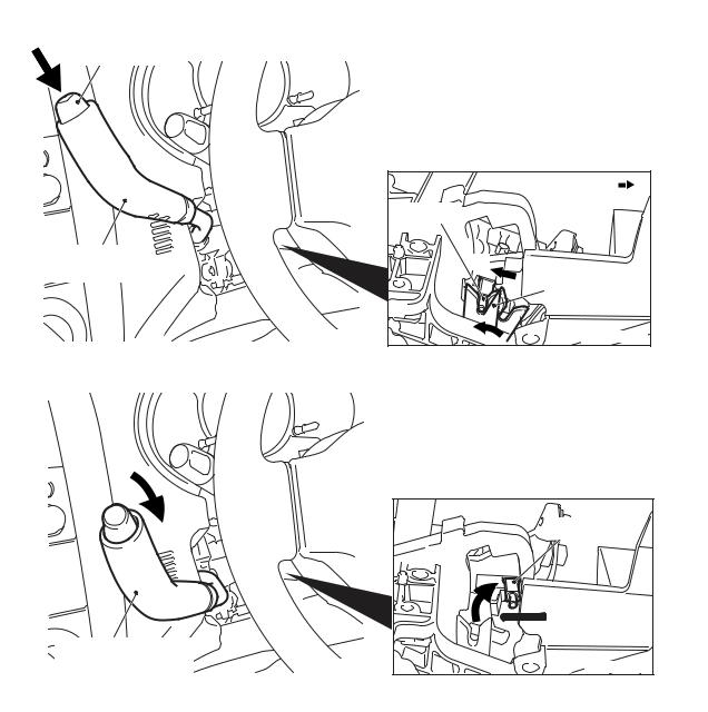
SHIFT LOCK MECHANISM
Only when the following two conditions are satisfied, the selector lever can be shifted from the P position to another position:
•When the brake pedal is depressed
•When the ignition key is in other than the LOCK (OFF) position
When the brake pedal is not depressed
Detent pin
Lever
Shiftlock cable
Lock cam
Rod
Stopper
Brake pedal
AC206902AB
When the selector lever is in the P position with the brake pedal not depressed, the shiftlock cable stopper keeps the lever locked so that the rod and lock cam do not move.
As a result of this, the pushbutton of the selector lever linked to the detent pin cannot be pressed and the selector lever cannot be shifted from the P position to another position.
When the brake pedal is depressed
Detent pin
Lever
Shiftlock cable
Lock cam
Rod
Stopper
Brake pedal
AC206903AB
When the brake pedal is depressed, the stopper is pulled by the shiftlock cable so that the lever becomes unlocked.
Then the lock cam linked to the rod can also rotate so that the selector lever can be shifted from the P position to another position by pressing the pushbutton.
NOTE: When the brake pedal is depressed with the ignition key in the LOCK (OFF) position, the selector lever cannot be shifted from the P position to another position.

CONTINUOUSLY VARIABLE TRANSMISSION (CVT) |
23-9 |
TRANSMISSION CONTROL |
|
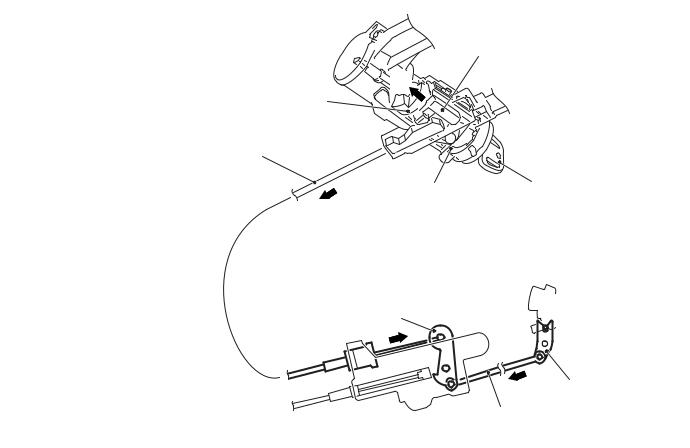
When the ignition key is in the LOCK (OFF) position or pulled out (With the selector lever in the P position)
Slider
Projection of rotor
Key interlock cable
Ignition key
Engine starting LOCK (OFF) position switch assembly
Lever
Lock cam
Rod
AC206911AB
In the engine starting switch assembly, the slider is engaged with the groove of the key interlock cable, and the slider is locked by the projection of the rotor so that the key interlock cable as well as the lever, rod, and lock cam does not move.
As a result of this, any attempt to shift the selector lever is prevented. The pushbutton on the selector lever cannot be pressed because the lock cam does not rotate, then the selector lever cannot be shifted from the P position to another position.
23-10 |
CONTINUOUSLY VARIABLE TRANSMISSION (CVT) |
|
TRANSMISSION CONTROL |
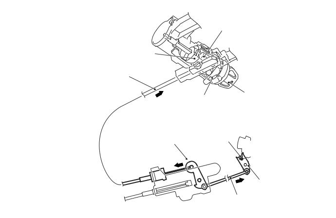
When the ignition key is in other than the LOCK (OFF) position (With the selector lever in the P position)
A
Projection of rotor
Key interlock cable
Engine starting switch assembly
Lever
Slider
Ignition key ACC to START position
Lock cam
Rod
AC206912AB
The rotor in the engine starting switch assembly has a notch between ACC and START so that the slider becomes unlocked.
Then the slider can move in the direction A as illustrated in the figure to allow the lock cam to rotate so that the selector lever can be shifted from the P position to another position by pressing the pushbutton.
NOTE: When the ignition key is in other than the LOCK (OFF) position with the brake pedal not depressed, the selector lever cannot be shifted from the P position to another position.
KEY INTERLOCK MECHANISM
When the selector lever is not in the P position, the ignition key cannot be turned to the LOCK (OFF) position and pulled out.

CONTINUOUSLY VARIABLE TRANSMISSION (CVT) |
23-11 |
TRANSMISSION CONTROL |
|
When pulling out the key with the selector lever in other than the P position
B
Projection of rotor
Key interlock cable
A |
Engine starting |
|
switch assembly |
||
|
Lever
 A
A
Slider
Ignition key ACC to START position
Lock cam
Rod
AC206912AC
The lock cam is kept in a rotated condition, and the key interlock cable is kept pulled in direction A as illustrated in the figure. In this state, the slider in the engine starting switch assembly is moved and locked in direction B as illustrated in the figure.
As a result of this, any attempt to turn the ignition key to the LOCK (OFF) position is prevented because the slider prevents the rotor from rotating, and the ignition key can only turn up to the ACC position and cannot be pulled out.
23-12 |
CONTINUOUSLY VARIABLE TRANSMISSION (CVT) |
|
TRANSMISSION CONTROL |
When pulling out the key with the selector lever in the P position
Slider
Projection of rotor
Key interlock cable
A |
Ignition key |
|
Engine starting |
||
ACC to START |
||
switch assembly |
||
position |
||
|
Lever |
Detent pin |
|
A |
Lock cam
Rod
AC206911AC
When releasing the pushbutton on the selector lever with the selector lever in the P position, the lock cam is rotated by the detent pin. Then the key interlock cable is moved by the lock cam in direction A as illustrated in the figure.
As a result of this, the slider in the engine starting switch assembly is unlocked. The rotor can then turn, and the ignition key can be pulled out by turning it to the LOCK (OFF) position.

GROUP 26
FRONT AXLE
CONTENTS
GENERAL INFORMATION . . . . . . . . 26-2

26-2 FRONT AXLE
GENERAL INFORMATION
GENERAL INFORMATION
The front axle consists of front hub, wheel bearing, knuckles and driveshafts, and has the following features:
•The wheel bearing incorporates magnetic encoder for wheel speed sensing.
•The driveshaft incorporates EBJ-TJ type constant velocity joint <4A9-CVT, 4A9-M/T (LS)>, EBJ-ETJ type constant velocity joint <4A9-M/T (VR)>, BJ-TJ type constant velocity joint <4G1>.
•The dynamic damper is mounted to reduce differential gear noise.
•The bracket assembly is mounted to reduce torque steer. < 4G1>
M2260000100701
• For environmental protection, a lead-free grease is used on the joints.
EBJ(Eight Ball Fixed Joint):The use of the smaller-sized eight balls inside the joint achieves weight saving and compact size compared with a BJ(Birfield Joint).
ETJ(Eco type Tripod Joint):This joint achieves weight saving and compact size compared with a TJ(Tripod Joint).
BJ:Birfield Joint
TJ: Tripod Joint
SPECIFICATIONS
Item |
|
|
|
4A9 |
|
|
4G1 |
|
|
|
|
CVT |
M/T |
|
|
|
|
|
|
|
|
|
|
|
|
|
|
|
LS |
VR |
|
|
|
|
|
|
|
|
|
Wheel bearing |
Type |
|
Double-row |
angular contact |
ball bearing |
|
|
|
|
|
|
|
|
|
|
|
Bearing (OD x ID) mm |
|
76 × 40 |
76 × 40 |
76 × 40 |
76 × 40 |
|
|
|
|
|
|
|
|
|
Driveshaft |
Joint type |
|
Outer |
EBJ |
EBJ |
EBJ |
BJ |
|
|
|
|
|
|
|
|
|
|
|
Inner |
TJ |
TJ |
ETJ |
TJ |
|
|
|
|
|
|
|
|
|
Length (joint to joint) |
|
LH |
377 × 21.2 |
377 × 21.2 |
379 × 23 |
352 × 24.9 |
|
× diameter mm |
|
|
|
|
|
|
|
|
RH |
688 × 21.2 |
688 × 21.2 |
664.3 × 23 |
378.2 × 24.9 |
|
|
|
|
|
|
|
|
|

FRONT AXLE |
26-3 |
GENERAL INFORMATION |
|
CONSTRUCTION DIAGRAM
<4A9> |
Strut assembly |
|
|
|
|
|
|
|
|
TJ (LH) <CVT, M/T (LS)> |
|
|
|
ETJ (LH) <M/T (VR)> |
|
|
Knuckle |
Dynamic damper |
|
|
|
|
Driveshaft (RH) |
Front hub |
|
|
|
|
|
Driveshaft (LH) |
Dynamic damper |
|
|
|
|
|
|
|
TJ (RH) <CVT, M/T (LS)> |
|
EBJ |
|
ETJ (RH) <M/T (VR)> |
|
|
|
|
|
Wheel bearing |
|
|
|
|
|
AC402000AG |
<4G1> |
|
|
AC403318 |
|
|
|
|
Strut assembly
Knuckle
TJ
Driveshaft (LH)
Front hub
Bracket assembly
TJ |
Driveshaft (RH) |
BJ
Wheel bearing
Dynamic damper
AC511705 AC

26-4 |
|
FRONT AXLE |
|
|
GENERAL INFORMATION |
||
|
Comparison between BJ and EBJ |
|
Comparison between TJ and ETJ |
BJ |
EBJ |
|
ETJ |
|
|
TJ |
|
|
|
|
|
AC306013AE

GROUP 27
REAR AXLE
CONTENTS
GENERAL INFORMATION . . . . . . . . 27-2
 Loading...