


 Loading...
®
RELAY® G70 / G75
ADVANCED GUIDE 
An Advanced User’s Guide to the Features and Functionality of Line 6 Relay G70 & G75 Wireless Systems
Relay G70/G75 Advanced Guide Table of Contents
Table of Contents
Quick Start.............................................................................................. |
1•1 |
Quick Start Steps..................................................................................... |
1•1 |
Factory Default Settings................................................................................. |
1•2 |
System Overview................................................................................... |
2•1 |
Key Features............................................................................................ |
2•1 |
What’s in the Box............................................................................................ |
2•2 |
Suggested Accessories.................................................................................. |
2•2 |
Relay TB516 G Transmitter................................................................... |
3•1 |
Transmitter Features................................................................................ |
3•1 |
Relay G70 & G75 Receiver.................................................................... |
4•1 |
Receiver Features.................................................................................... |
4•1 |
The Home Screen.................................................................................... |
4•3 |
How To.................................................................................................... |
5•1 |
About Scenes.......................................................................................... |
5•1 |
Edit Mode................................................................................................. |
5•1 |
Editing Scene Parameters.............................................................................. |
5•1 |
Renaming a Scene.......................................................................................... |
5•3 |
Selecting a Channel (Manual and Auto Scan)................................................ |
5•3 |
Setting the Cable Tone Feature...................................................................... |
5•4 |
Configuring the Receiver Outputs A, B and C................................................ |
5•4 |
Setting the Gain for Each Scene..................................................................... |
5•5 |
Changing the Switch Color Ring.................................................................... |
5•5 |
Removing a Scene.......................................................................................... |
5•6 |
Adding a Scene.............................................................................................. |
5•6 |
Adjusting the Receiver’s LCD Screen Brightness........................................... |
5•7 |
Configuring the Aux Input............................................................................... |
5•7 |
Checking the Info Details for your Receiver and Transmitters........................ |
5•8 |
Performing a Factory Reset............................................................................ |
5•8 |
ii
Relay G70/G75 Advanced Guide Table of Contents
Adding Additional Transmitters to your Receiver |
.................................. 5•9 |
Adding Transmitters Using the Auto Scan Method........................................ |
5•9 |
Adding Transmitters Using the Manual Method........................................... |
5•10 |
Adding New Scenes for a Single Transmitter....................................... |
5•11 |
Using One Transmitter with Multiple Instruments......................................... |
5•11 |
Footswitch / Select Button Control...................................................... |
5•12 |
Color LED Ring Indicator...................................................................... |
5•12 |
Using the Built-in Tuner & the Tuner Output......................................... |
5•13 |
Using the Tuner Output................................................................................. |
5•13 |
Transmitter Details (Relay TB516 G)..................................................... |
5•13 |
Locking Guitar Cable Connection................................................................. |
5•13 |
Using Standard Guitar Cables...................................................................... |
5•14 |
Transmitter User Interface............................................................................ |
5•14 |
Batteries for your Transmitter....................................................................... |
5•15 |
Battery Status Light...................................................................................... |
5•15 |
Installing Firmware Updates................................................................. |
5•15 |
Tips for Best Operation & Hook Up Examples.................................... |
6•1 |
|
About the Quad-Internal Antenna Array................................................. |
6•1 |
|
Interference Sources............................................................................... |
6•1 |
|
Pedalboard Mounting the G70 Receiver................................................ |
6•3 |
|
To Each Their Own Channel.................................................................... |
6•4 |
|
Example Hook Up Diagrams................................................................... |
6•4 |
|
G70/G75 Basic Single Instrument Hook Up................................................... |
6•4 |
|
G70 |
Electric + Acoustic Guitar Hook Up........................................................ |
6•5 |
G75 Bass Guitar to Amp + PA Hook Up......................................................... |
6•5 |
|
G70 |
Acoustic Guitar Direct to PA + Powered Monitor Hook Up.................... |
6•6 |
G70 |
Electric and Acoustic Guitar to Two Amps + PA Hook Up...................... |
6•6 |
Additional Resources |
............................................................................7•1 |
Tutorials.................................................................................................... |
7•1 |
Product Guides........................................................................................ |
7•1 |
Software Downloads............................................................................... |
7•1 |
Gear.......................................................................................................... |
7•1 |
Support.................................................................................................... |
7•1 |
iii
Relay G70/G75 Advanced Guide Table of Contents
Appendix: Product Specifications....................................................... |
A•1 |
Relay G70 & G75 System Specifications................................................ |
A•1 |
Relay TB516 G Transmitter Specifications............................................. |
A•1 |
Relay G70 & G75 Receiver Specifications.............................................. |
A•2 |
Relay G70 Receiver Dimensions.................................................................... |
A•3 |
Relay G75 Receiver Dimensions.................................................................... |
A•4 |
Line 6 Relay, POD, Variax and James Tyler Variax are trademarks of Line 6, Inc. All other product names, trademarks, and artists’ names are the property of their respective owners, which are in no way associated or affiliated with Line 6. Mac® is a trademark of Apple, Inc. registered in the U.S. and other countries. Windows® is a registered trademark of Microsoft Corporation in the United States and/or other countries.
Copyright © 2015 Line 6, Inc.
iv

Relay G70/G75 Advanced Guide |
Quick Start |
Quick Start
We always recommend reading through the manual first, but if you want to get started right away with your Line 6 Relay® system, please follow the steps below.
Relay G70
NAV EDIT
PUSH TOSET
Out A |
SELECT / MUTE |
Relay G75
5V USB |
Amp |
|
OR
Locking
Collar

Guitar
Transmitter
Quick start hook up diagram
Quick Start Steps
1.Remove the Receiver, Transmitter, power supply and guitar cable from the packaging.
2.Place the Receiver in a location where the top of the unit is not obstructed by any
metal, computers, mobile phones or tablets. Ensure that there are no Transmitters other than the Relay TB516 G in use within 6 feet (2 meters) of the Receiver.
3.Use the supplied USB cable to connect the 5V power supply to the Micro-USB connection on the Receiver and plug the power supply into an AC outlet.
4.Connect the Receiver’s Output A (1/4”) to your amplifier input or the input of the next pedal on your pedalboard.
5.Turn the power switch on the rear of the Receiver On.
6.Insert 2 fresh AA batteries in the Transmitter.
7.Plug the supplied guitar cable into the Transmitter’s locking connector Input, turning the locking collar until it is snug (do not over-tighten - the collar just needs to be secured).
8.Plug the other end of the guitar cable into your guitar.
9.Turn On the Transmitter, check for a green light (yellow or red indicate low battery) and start playing and enjoying wireless freedom!
1•1
Relay G70/G75 Advanced Guide |
Quick Start |
Factory Default Settings
ThefactorydefaultsettingsfortheReceiverandTransmitterarealreadyconfiguredasfollows, allowing them to work together right out of the box. In the following chapters we show how you can customize these settings and create your own additional “Scenes” as well.
•Name: SCENE1
•Channel: 1
•Cable Tone: OFF
•Active Output: A+C (outputs A and C both active)
•Gain: 0dB (0 = unity gain)
•Switch Color: Green
•Add Scene: CH. 1
•LCD Brightness: High
•Aux In: Always On
1•2
Relay G70/G75 Advanced Guide |
System Overview |
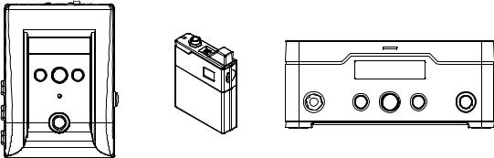
System Overview
Welcome to the Relay G70/G75 Advanced Guide. This guide contains details on the
features and functionality of the Line 6 Relay® G70 & G75 Receivers and TB516 G Wireless Transmitter. Please also visit http://line6.com/support/manuals/ for all the latest Line 6 product documentation, including the Relay G70/G75 Pilot’s Guide.
|
Relay TB516 G Guitar |
|
|
Relay G70 Receiver |
Transmitter |
Relay G75 Receiver |
|
Model TB516G |
|||
Model RS516 |
Model RT516 |
||
P/N 98-033-0069 |
|||
|
|
The Relay G70 and G75 Receivers and TB516 G Transmitter components
Key Features
•Up to 16 channels of lossless 24-bit audio for uncompromised tone
•Industry-leading audio quality proven on major tours worldwide
•Use multiple Transmitters and switch guitars with ease*
•Best-in-class dynamic range with less than 1.5ms of latency
•Noise-free, full-frequency operation up to 200 feet from Receiver
•Locking 1/4” guitar input on Transmitter—no special cables required
*Extra Transmitters sold separately
•Choice of compact “stomp box” or “amp-top” style Receiver, for the utmost flexibility in cable routing and access to the user interface
•Two selectable 1/4” guitar outputs with configurable On/Off, Gain, and Cable Tone per guitar or Scene
•Additional dedicated 1/4” “always on,” Output jack for direct connection to your tuner
•A breakthrough configurable XLR direct output greater than 120dB dynamic range,
24-bit accuracy audio performance and wireless freedom
•1/4” Auxiliary Input jack on Receiver to connect a wired guitar for ultimate performance flexibility
•Use of Alkaline (provided) or Rechargeable AA batteries (available separately).
•Rugged metal Transmitter and Receiver construction.
2•1
Relay G70/G75 Advanced Guide
What’s in the Box
•Relay TB516 G Guitar Transmitter
•Stomp-style Receiver (Relay G70 only)
•Amp-top Receiver (Relay G75 only)
•24” Guitar Cable 1/4” to 1/4” Straight TS, with collar lock
•USB-A to Micro-USB cable
•Universal USB Power Supply (5V-1A) kit with international adapter kit.
•Pack of 6 color-coded Transmitter
ID hex nuts (Green, Blue, Orange,
Purple, Aqua, White: 1 each)
•2 AA Batteries
•Pilot’s Guide and Warranty documentation
System Overview
Suggested Accessories
•Additional Relay TB516 G Transmitter for each guitar used
•Line 6 DC-1g or DC-3g 9V power adapter (for optionally powering Receiver via its 9VDC connection)
•Right angle guitar cable with locking plug
•Replacement or spare straight guitar cable with locking plug
•Custom Line 6 Transmitter pouch
•Replacement Transmitter belt clips
•Replacement Transmitter ID hex nuts
2•2

Relay G70/G75 Advanced Guide |
Relay TB516 G Transmitter |
Relay TB516 G Transmitter
This Chapter provides details on the Line 6 Relay® TB516 G Wireless Transmitter unit. A TB516 G is included in the retail box with each Relay G70 or G75 system. It can also be purchased individually, allowing you to expand your wireless setup with individual Transmitters for as many instruments as you like. Be sure to check out the “How To...” Chapter for tips on configuring Transmitters for use with your Relay Receiver.
Transmitter Features
6
1 |
|
2 |
|
3 |
|
|
|
|
|
8 |
|||
|
|
|
|
|
|
9 |
7 |
4
10
5
11
The Relay TB516 G Transmitter
1.Battery Status – This LED illuminates green when the Transmitter is powered On, and more than 1 hour of battery operation time remains. It flashes yellow when less than 1 hour, and flashes red when less than 30 minutes of battery operation time remain.
Note: Battery operation time is calibrated for 2x AA Alkaline batteries - actual times may vary when using non-alkaline batteries.
2.Guitar Input – Plug in the included guitar cable here.* To lock the cable, simply plug in the end with the locking collar and gently twist so that it fastens onto the exposed thread of the Transmitter’s input jack. DO NOT OVERTIGHTEN. To unlock, spin the collar counter-clockwise and pull the plug out.
*Note: You can use regular ¼” guitar cables as well.
3•1

Relay G70/G75 Advanced Guide |
Relay TB516 G Transmitter |
If you own more than one Transmitter, it’s a good idea to use one of the different colored hex nuts included in the box to help you easily identify each Transmitter at a glance. Your Relay Receiver’s
Scenes allow you to configure a matching LED color as a reminder for which Transmitter is in use
- see “Changing the Switch Color Ring” on page 5•5.
Remove the existing black nut and replace it with one of the included 6 colored hex nuts
3.Power On/Off – Turns power On when working batteries are installed. The Transmitter will automatically sync with the Receiver in about 1 second.
4.Antenna – The calibrated internal antenna avoids damage or deformity in normal use. Avoid covering the antenna with metallic fabrics or accessories, and avoid direct contact with parts of the performer’s body for best results. Putting the Transmitter in your front pants pocket may reduce range, so use a back pocket if you don’t want it on the strap or a belt
5.Battery Door Release – Press on both sides of the Transmitter at the same time to open the battery door. See #11 below for details.
6.Channel Display – Channel 1-16 is indicated after pressing the Channel Select buttons (see #7).
7.Channel Select – Slide the Battery Door (#11) open to access these buttons. Press the p Up or q Down button once to light the Channel number indicator. Press either Up or Down to change
the Channel. The Channel number will flash in theChannel Display (#6) for 2 seconds* after the Channel is selected, indicating the Channel change has been executed.
*Note: The transmitted Channel does not immediately change while selecting the Up and Down buttons in order to avoid conflicting with other active Transmitters.
8.Auto-Sleep Switch – Slide the Battery Door (#11) open to access this switch. Place the switch in the  position to enable the Auto-Sleep feature. When enabled, the Transmitter will automatically go into Standby/Sleep mode after 2 minutes without any movement or audio detected. With this feature On you can turn down your volume knob and place your guitar in a stand during set breaks and minimize your battery drain without having to power the Transmitter Off.
9.Micro USB – USB connectivity is used for firmware updates, should they be needed in the future. The latest firmware updates can be found athttp://line6.com/software/
10.Battery Compartment – Requires two AA batteries for proper operation.
11.Battery Door – Slides open in 2 stops: the 1st stop allows access to the Channel Select (#7) buttons and Auto-Sleep Switch (#8), the 2nd stop provides full access to removable batteries.
3•2

Relay G70/G75 Advanced Guide |
Relay G70 & G75 Receiver |
Relay G70 & G75 Receiver
This Chapter provides details on the features and functionality of the Line 6 Relay® G70 and G75 Wireless Receivers.
Receiver Features
1 |
2 |
167 |
3 |
4 |
5 |
6 |
7 |
154
14 16
9
7
4
3
|
|
|
|
|
|
|
|
|
|
|
|
|
|
|
|
|
8 |
|
9 |
|
10 |
|
11 |
|
|
|
|
|
|||||
|
12 |
|
13 |
|||||||||||||
|
|
|
|
|||||||||||||
Relay G75 and G70 Receivers
15
2 5 6 1
|
|
|
|
|
14 |
|
NAV |
|
EDIT |
|
10 |
P |
|
T |
|
|
11 |
U |
E |
|
|
|
|
|
SH TOS |
|
|
|
|
|
|
|
|
16 |
8 |
|
|
|
|
|
|
|
|
|
|
|
12 |
SELECT / MUTE |
|
|
13 |
||
|
|
|
|
|
|
1.Power: Use this switch to power the Receiver On or Off.
2.Micro USB: Use as primary DC (5VDC /1A) power with included cable and AC adapter, and for the installation of firmware updates.
3.Out A: A 1/4” unbalanced, full-performance output intended to drive a guitar/bass amplifier, stomp box or multi-effects device inputs.
4.Out B: Like Out A, this is a 1/4” unbalanced output, but can be configured separately within your Scenes - such as for connecting to an additional amplifier or separate monitor system.
5.Ground Lift: Toggle this switch to disable pin 1 of the XLR Out C for “ground lift,” which can be used to remedy grounding noise issues.
6.Out C: An XLR balanced output with ground lift - perfect for connecting to a PA, or other XLR inputs. This output can be configured separately within your Scenes fromOut A and Out B.
7.Tuner Out: A 1/4” output with a guitar level signal. The Tuner Out is always active and cannot be
muted via Scene control, which is intended for connecting to a separate Tuner. Note that your Relay Receiver also includes its own built-in Tuner - see page 5•13.
4•1
Relay G70/G75 Advanced Guide |
Relay G70 & G75 Receiver |
8.Aux In: An Auxiliary Input for wired performance - handy for keeping another guitar plugged in, or as a “safety net” in case of forgotten or failing Transmitter batteries. The default mode for the Aux In is “Always On,” as set in the global preferences. In this mode the Aux In is active in any Scene
where the assigned Transmitter is Off, or in any Scene where theAux In is set as the Channel input. If the global preference is set to “Scene Only” the Aux In will only be active in Scenes
where it is the designated Channel input.
9.Home Button: This navigation button returns the LCD to home screen display content. See “The Home Screen” on page 4•3.
10.Nav/Select Encoder: This is your primary navigation control. Rotate the Encoder knob to choose a selection - push it to activate the current selection. When the Home Screen is displayed, the
Encoder allows you to scroll up or down through all the Scenes you have created. Press the Encoder to activate a Scene. Also see “Edit Mode” on page 5•1 for details on navigating the
editable parameters for your device.
11.Edit Button: Press to enter Edit Mode where you can access Scene and Input parameters. See
“Edit Mode” on page 5•1.
12.Select/Mute Switch: Use this footswitch (G70) or button (G75) to cycle sequentially through existing Scenes. Press and hold the switch for 2 seconds to Mute all outputs and/or activate the internal Tuner.
Note: The Receiver’s built-in Tuner is available only when nothing is plugged into the Tuner Output.
13.Switch Color Ring: The color of this LED ring surrounding the Select/Mute switchisuser-definedper
Scene, providing a visual indicator for which Transmitter is currently active - see the Transmitter details on page 3•1.
The Color Ring maintains steady brightness when the RF signal is good and flickers whenever the RF reception is poor. It also blinks to indicate several different states - see“Edit Mode” on page 5•1 for details.
14.LCD Display: This monochrome LCD is the main information source for your wireless setup. Its Home Screen displays active Transmitter Channel or Input, active Output Routing and Battery Life. Its Edit Mode screen displays settings for cable tone, gain, and other preferences.
15.9VDC Input: Optional 9VDC 500mA DC.
Note: The compatible Line 6 DC-1g or DC-3g 9V power supplies are available separately from your Line 6 dealer, or from the Line 6 Online Store.
16.Audio LED: Lights green to indicate audio reception. Lights red to indicate clipping. The Audio LED is also utilized as a tuning indicator when your Receiver is in Tuner Mode - It turns red when sharp or flat, and green when within ± 3 cents of the target note (seepage 5•13 for more about the built-in Tuner).
17.Remote (G75 only): Connect a momentary footswitch* to provide foot-operated Scene changes, similar to the footswitch functionality on the G70.
*Works with either momentary closed or open footswitch types. The Remote jack automatically detects when a footswitch is connected, and can detect polarity switch changes as well.
4•2
Loading...