


Spider Valve 212
Pilot’s Guide
Manuel de pilotage
Pilotenhandbuch
Pilotenhandboek
Manual del Piloto
®
An in-depth exploration of the technologies and
pulsing tonal pleasures of Spider Valve.
40-00-0123 Electrophonic Limited Edition available @ www.line6.com/manuals Rev A
WARNING: To reduce the risk of fire or
electric shock, do not expose this appliance to
rain or moisture.
NOTICE: This equipment has been tested and found to comply with the limits for a Class B digital device pursuant
to Part 15 of FCC Rules. Operation is subject to the following two conditions: (1) This device may not cause harmful
interference, and (2) this device must accept any interference received, including interference that may cause undesired
operation.
CAUTION: To reduce the risk of fire or electric shock,
do not remove screws. No user-serviceable parts inside. Refer
servicing to qualified service personnel.
The lightning symbol within a triangle means
“electrical caution!” It indicates the presence
of information about operating voltage and
potential risks of electrical shock.
The serial number can be found on the back panel of your Spider Valve. It’s the number that begins
with “(21)”. Please note it here for future reference:
SERIAL NO:
The exclamation point within a triangle
means “caution!” Please read the
information next to all caution signs.
Please Note:
All product names referred to in this manual are
trademarks of their respective owners, which are in
no way associated or affiliated with Line 6. These
trademarks of other manufacturers are used solely to
identify the products of those manufacturers whose
tones and sounds were studied during Line 6’s sound
model development.

You should read these Important Safety Instructions
Keep these instructions in a safe place
Before using your Spider Valve, carefully read the applicable items of these operating instructions and the safety suggestions.
1. Obey all warnings on the amp and in the Spider Valve Manual.
2. Connect only to AC power outlets rated 100-120V or 200-240V 47-63Hz (depending on voltage range of the power supply;
refer to label on the unit).
3. Service is required when the apparatus has been damaged in any way, such as:
• power-supply cord or plug is damaged
• liquid has been spilled or objects have fallen into the apparatus
• the unit has been exposed to rain or moisture
• the unit does not operate normally or changes in performance in a significant way
• the unit is dropped or the enclosure is damaged.
4. Do not touch tubes during operation. Wait until you are certain that the tubes have cooled sufficiently, approximately 1020 minutes after the amp has been powered off.
5. Do not place near heat sources, such as radiators, heat registers, or appliances which produce heat. Keep the rear of the unit
at least three inches from walls or other items that might block heat radiation.
6. Do not block any of the ventilation openings or use in an enclosed space.
7. Guard against objects or liquids entering the enclosure. Do not use or place unit near water.
8. Do not step on power cords. Do not place items on top of power cords so that they are pinched or leaned on. Pay particular
attention to the cord at the plug end and the point where it connects to the amp.
9. Unplug the amp when not in use for extended periods of time. Unplug the amp during lightning storms.
10. Clean only with a damp cloth.
11. Do not defeat the safety purpose of the grounding type plug. A grounding type plug has two blades and a third grounding
prong. The third prong is provided for your safety. When the provided plug does not fit into your outlet, consult an
electrician for replacement of the obsolete outlet.
12. Only use attachments/accessories specified by the manufacturer.
13. Prolonged listening at high volume levels may cause irreparable hearing loss and/or damage. Always be sure to practice “safe
listening.”
14. Always make sure that a speaker cabinet or equivalent load device is connected to the appropriate speaker output before
turning the amp on.
15. Always replace the Sovtek 5881 power tubes with a matched set of the same type at the same time. Line 6 recommends that
this work be performed by an Authorized Service Center.
16. When changing the output tubes please be sure to have the bias checked and adjusted, if necessary. Line 6 recommends that
this work be performed by an Authorized Service Center.
17. Always refer routine maintenance and service issues to an Authorized Line 6 Service Center. For your convenience, these
can be located online at http://www.line6.com/support/servicecenters or by calling Line 6 Customer Service at 818-575-
3600.
Spider Valve Pilot’s Guide © 2007 Line 6, Inc.

Table of Contents
The Spider Valve Story .............................................................. i
Best of Both Worlds .............................................................................................i
Reinhold Bogner ..................................................................................................i
Spider Valve – This is a Real Tube Amp ............................................................ii
Controls & Connections ........................................................ 1•1
Presets, Tuner & More ........................................................... 2•1
Presets ............................................................................................................. 2•1
Saving Presets ................................................................................................. 2•1
Tap Button “Extra” Functions ........................................................................ 2•2
Special Hidden Functions .............................................................................. 2•3
Factory Reset .................................................................................................. 2•3
Modeled Amps & Effects ....................................................... 3•1
Which Amps & Effects Are Modeled? .......................................................... 3•1
Effects ............................................................................................................. 3•3
Using Your Feet ...................................................................... 4•1
FBV2 .............................................................................................................. 4•1
FBV Express ................................................................................................... 4•2
FBV Shortboard ............................................................................................. 4•4
Maintenance and Troubleshooting ....................................... 5•1
Tubes .............................................................................................................. 5•1
Tube Troubleshooting and Maintenance ....................................................... 5•1
General Troubleshooting ............................................................................... 5•2
Fuses ............................................................................................................... 5•2

The Spider ValVe STory
Best of Both Worlds
Welcome to the Line 6 family and thanks for choosing Spider Valve, the first-born of a
new breed of Modeling Tube Amplifiers. We’ve worked hard to push the envelope of guitar
amplification with this revolutionary product.
We all know somebody who’s jacked a POD® into a tube amp. This kind of rig gives you
the best of both worlds: the killer range of our award-winning amp and effects models,
coupled with the warmth and performance of a tube amp. Over the years, we’ve constantly
been asked to design an amp using this approach. We listened, but we waited patiently
until everything was in place to deliver a truly exceptional amplifier. That time is now. We
recently entered into a partnership with a true legend in tube amp design, Reinhold Bogner.
Together we have designed Spider Valve, a world-class tube amp with the versatility of a
Line 6 modeler.
Forward
i
Reinhold Bogner
Reinhold Bogner had been designing and building amplifiers long before leaving Germany
in 1989. Moving to Los Angeles he quickly gained the trust of many influential players,
including Steve Stevens, Dan Huff, Allan Holdsworth, Mike Landau, and Steve Vai,
who sought out his skill at modifying and custom building their amps. Eddie Van Halen
entrusted Reinhold to overhaul and revitalize Eddie’s arsenal of amps. Eddie was pleased.
Bogner Amplification was born.
Forward
ii
To create Spider Valve, our team of guitar-slinging engineers worked tirelessly with
Reinhold. By tapping into his boutique design sensibilities, we were able to fully
integrate our modeling front end into his world-class tube amp design, conjuring up the
rich harmonics, subtle compression and signature attitude of a great vintage amplifier.
The outcome of our work together has exceeded our highest expectations, delivering an
experience that is much more than the sum of its individual parts.
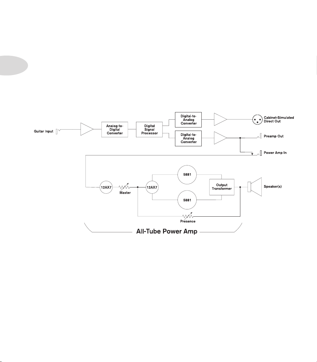
Spider Valve – This is a Real Tube Amp
The signal flow of the Spider Valve 112 and 212 is shown below:
As you can see, Spider Valve consists of a complete Class AB tube amplifier fed by a digital
front end, which houses all the magic of our amp and effect models. Make no mistake;
these are not “marketing tubes”. This is a real tube amp. 12AX7 pre-amp tubes, which are
always working to provide the harmonic richness and compression of a great vintage tube
amp, drive the phase splitter and 5881 power amp complement.
Spider Valve truly offers the “best of both worlds” — affording you a tremendous range of
Line 6 tone and effects with the vibe and stage-proven performance of a world class tube
amp. We hope you enjoy playing these amps as much as we enjoyed creating them.
Controls & Connections
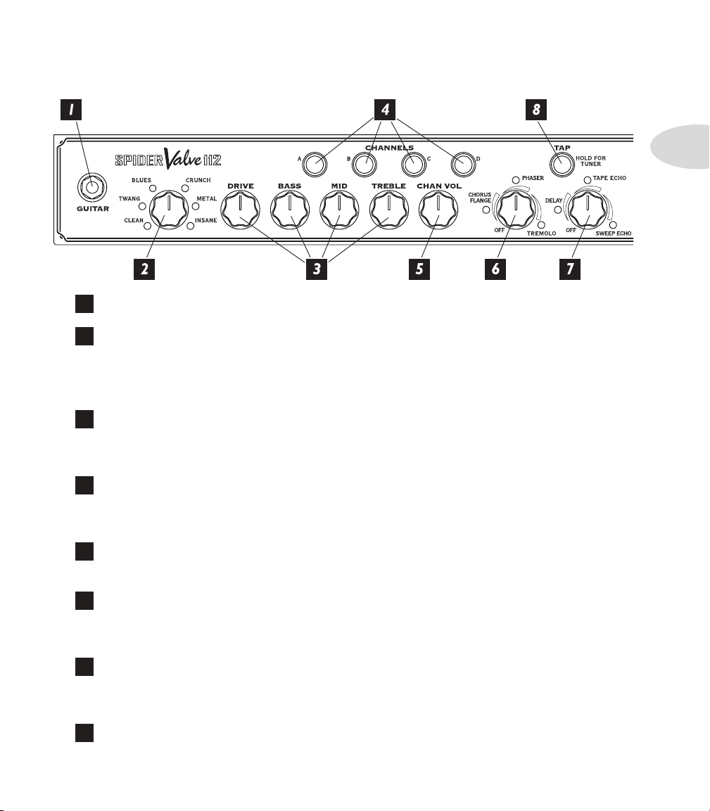
ConTrolS & ConneCTionS
Guitar In – Plug in here.
1
Amp Models – Spin this knob to select one of twelve Amp Models, which are
2
inspired by particular voicings or channels on some of our favorite amps All the Spider
Valve controls except for Master and Presence will automatically be set to sound great
with that Amp Model, so you can just play! See Chapter 3 for more info.
Tone Controls – Drive is like the volume or gain knob on other amps; controls
3
how much “dirt” you get in your sound. Bass, Mid, and Treble controls are customized
for each Amp Model to give you optimal tonal control.
1•1
Channel Memories – Four programmable channels come pre-loaded with
4
great factory presets. These buttons are also used when saving user presets. See Chapter 2
for more information.
Channel Volume – This control helps you balance the volumes of different
5
amp-and-effect setups that you store in your Spider Valve’s channels.
Mod Effects – Turn this knob to pick chorus/flange, phaser or tremolo, with a
6
range of settings – from subtle to overpowering – for each effect. The LED shows the active
effect.
Delay – picks delay, tape echo or sweep echo, with a range of mix settings from low
7
to high. The LED shows the active effect and the Tap button LED flashes the delay time.
Tap the Tap button to change the delay time.
Tap Button and LED – Tap on the Tap button a few times to set the delay
8
time, press and hold to activate the built-in Tuner.
Controls & Connections
1•2
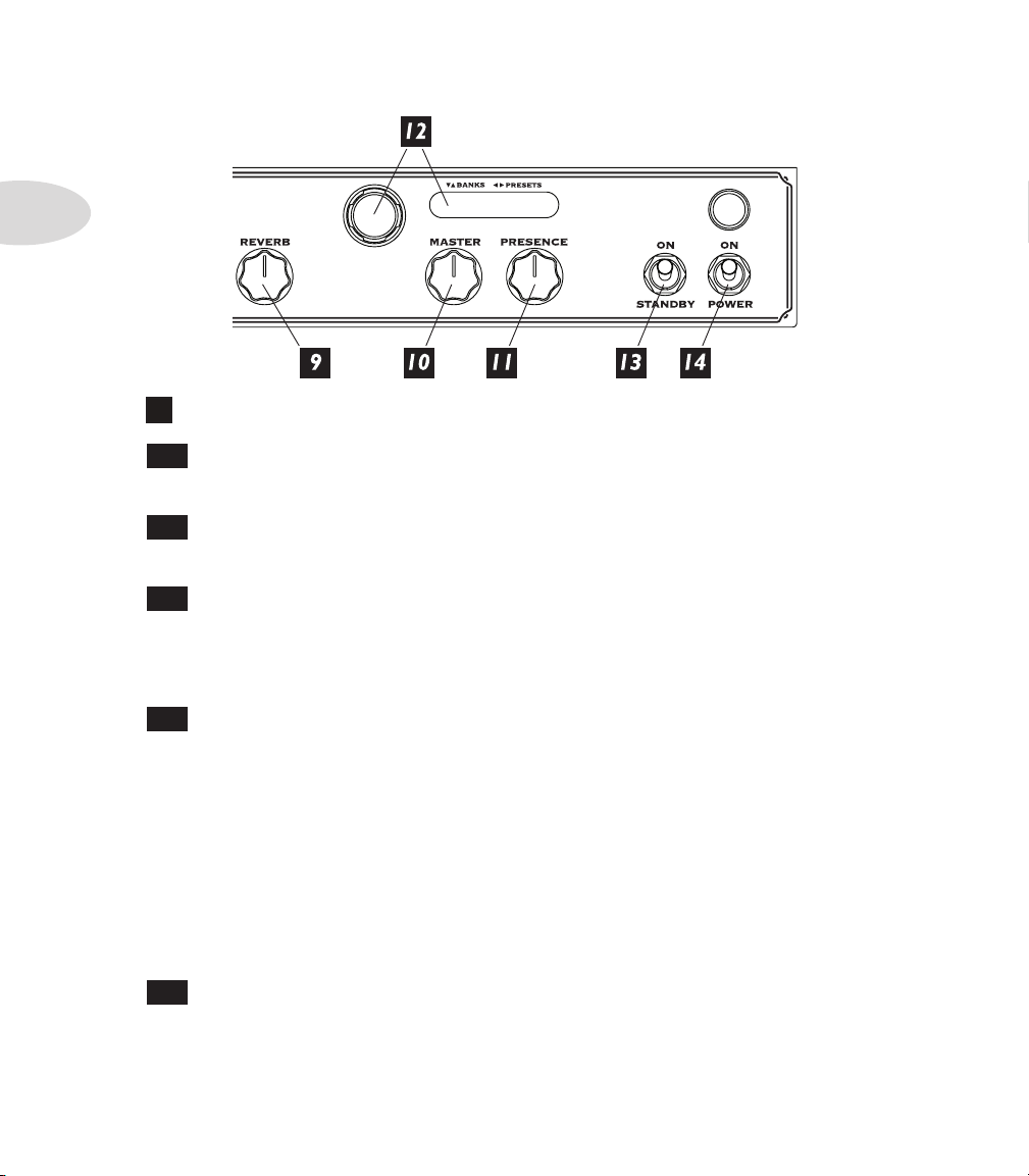
Reverb – Dial up more or less verb.
9
10
Master Volume – Controls the overall volume of the amplifier, without
affecting your tone. This is a passive, analog control that is tied directly to the tube amp.
11
Presence – Controls the brightness of the tube power amp. This is also a passive,
analog control that is tied directly to the tube amp.
12
Navigator & Channel Display – Navigate up and down to go through
the various banks of presets (user, artist based, song based). Navigate left and right to select
from different sounds in each of those banks. The display will indicate which preset you
have selected both alphanumerically (e.g. 01A, 60S) and by name (e.g. Crunchzilla).
13
Standby – Use this switch to silence the on-board speakers without turning the
amp off. For optimum tube life, it’s important to use this switch when powering up the
amp as follows:
Set the Standby switch to the Standby (down) position.
•
Set the Power switch to the On (up) position.
•
Let the amp warm up for at least a minute.
•
Set the Standby switch to the On (up) position
•
Rock out!
•
14
Power – Turns the amp on or off. Be sure to always have speaker(s) connected
BEFORE turning the power on, and speakers should only be disconnected AFTER the
power is turned off.
Controls & Connections
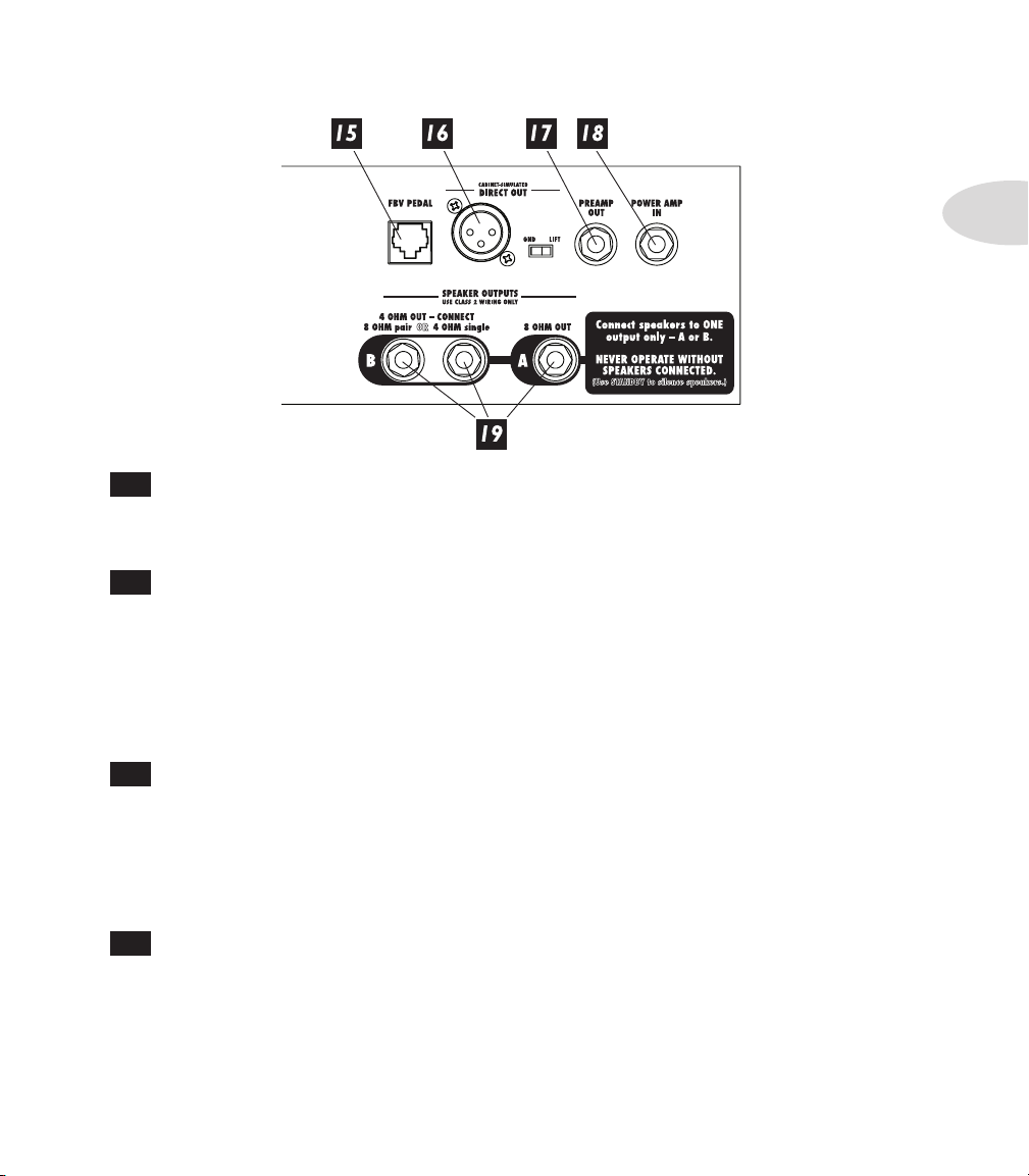
15
FBV Pedal – Plug in one of our optional Line 6 FBV foot controllers for channel
switching, tap tempo, effects on/off control, wah/volume pedals, access to 32 more channel
memories, and tuner capabilities. See Chapter 4 for more details.
16
Balanced Direct Out and Ground Lift – Provides full-time POD®
-quality tone for studio-direct recording.
1•3
The ground lift switch can be used to eliminate hum or buzz that might be heard when
connecting to equipment that is in another location. Place the switch in the LIFT position
to internally “lift” (disconnect) the Pin 1 ground connection of the XLR or leave it in the
GND position to leave the Pin 1 ground connection intact.
17
Preamp Out – This is a pre-tube amp output than can be used for all sorts of
things. For one, you can drive a second amp from the Spider Valve’s modeling pre, or you
can use it as an “effects send” to feed outboard effects. You can then use the Power Amp
In either as an input from another preamp or multi-effects unit like the POD X3 Live or as
a “series effects return”. However, we don’t recommend that you use this output for direct
recording – that’s what the Balanced Direct Out is for.
18
Power Amp In – This is a direct connection to the all-tube power amp,
including the 12AX7 preamp tubes, matched 5881 power amp tubes, Master, and Presence
controls.
Plugging into this jack will internally disconnect the Preamp Out feed to the tube
amp.
 Loading...