


 Loading...
STAGESCAPE M20d
ADVANCED GUIDE
Firmware Version 1.20
Rev D |
© 2013 Line 6, Inc. |
Table of Contents
M20d Overview ....................................................................................... |
1•1 |
Firmware v1.20 Update ...................................................................... |
1•1 |
Hardware Legend ............................................................................... |
1•2 |
Main Toolbar ....................................................................................... |
1•4 |
Stage Icon Gallery .............................................................................. |
1•5 |
Controller Strips ................................................................................. |
1•6 |
Contextual Browsers .......................................................................... |
1•6 |
Hardware Encoders ............................................................................ |
1•8 |
Setup Mode ............................................................................................. |
2•1 |
Creating Input Channels .................................................................... |
2•1 |
I/O Panel ............................................................................................ |
2•4 |
Customizing Stage Icons ................................................................... |
2•6 |
Auto Trim ............................................................................................ |
2•9 |
Saving & Loading Setups ................................................................. |
2•11 |
Group Encoders ............................................................................... |
2•13 |
Channel Presets Overview ............................................................... |
2•14 |
Tweak Mode ............................................................................................ |
3•1 |
Quick Tweak ....................................................................................... |
3•2 |
Deep Tweak ........................................................................................ |
3•9 |
Input Settings ................................................................................... |
3•11 |
Monitor Settings ............................................................................... |
3•12 |
Global FX Settings ........................................................................... |
3•14 |
Media Player .................................................................................... |
3•16 |
Recording ................................................................................................ |
4•1 |
Quick Capture .................................................................................... |
4•2 |
Multitrack Recording .......................................................................... |
4•3 |
Streaming ........................................................................................... |
4•8 |
Monitor Mode .......................................................................................... |
5•1 |
Channel Monitor Levels ..................................................................... |
5•2 |
FX Monitor Levels .............................................................................. |
5•4 |
Perform Mode .......................................................................................... |
6•1 |
Saving & Loading Scenes .................................................................. |
6•2 |
Encoder Assignments ........................................................................ |
6•4 |
Mute & Solo ........................................................................................ |
6•4 |
Footswitches ............................................................................................ |
7•1 |
Footswitch View ................................................................................. |
7•2 |
Assignment Options ........................................................................... |
7•2 |
Managing L6 LINK Devices ...................................................................... |
8•1 |
Auto-assign L6 LINK Speakers ON .................................................... |
8•2 |
Auto-assign L6 LINK Speakers OFF .................................................. |
8•5 |
Speaker Controls ............................................................................... |
8•6 |
System Settings ....................................................................................... |
9•1 |
Wi-Fi Remote Setup ........................................................................... |
9•2 |
Backup & Restore .............................................................................. |
9•6 |
Firmware Updates .............................................................................. |
9•7 |
Setup Examples ..................................................................................... |
10•1 |
Duo With Backing Tracks ................................................................. |
10•1 |
Rock Band ....................................................................................... |
10•6 |
Electronic Artist .............................................................................. |
10•11 |
Setup Tips ...................................................................................... |
10•17 |
Appendix A: Channel Processing |
............................................................. A•1 |
Appendix B: Global FX .............................................................................. |
B•1 |
Appendix C: Preset DSP Types ................................................................. |
C•1 |
Appendix D: Fader View ........................................................................... |
D•1 |
Fader View Toolbar ............................................................................. |
D•2 |
Fader Assign Menu ............................................................................ |
D•3 |
Lower Encoder Assign Menu ............................................................. |
D•4 |
Inputs Select ...................................................................................... |
D•5 |
FX Select ............................................................................................ |
D•7 |
Outputs Select ................................................................................... |
D•9 |
Other Toolbar Buttons ...................................................................... |
D•11 |
Workflow Tips ................................................................................... |
D•12 |

M20d Overview
M20d Overview
Welcome to the StageScape™ M20d Advanced Guide. |
1•1 |
|
StageScape M20d is the world’s first smart mixing system for live sound. Utilizing a ground- |
|
|
breaking touchscreen visual mixing environment,StageScape M20d streamlines the way you mix |
|
|
so you can get your sound dialed in quickly and stay in the creative zone. |
|
|
This M20d Advanced Guide contains in-depth details of your M20d’s features and functionality, and |
|
|
includes comprehensive information on the following: |
|
|
• Setup Mode, Tweak Mode, Record Mode, Monitor Mode, Perform Mode |
|
|
• |
Assigning Footswitches |
|
• Managing L6 LINK Devices |
|
|
• |
System Settings |
|
• |
Setup Examples |
|
• |
Channel Processing |
|
• |
Global FX |
|
• |
Preset DSP Types |
|
Before You Begin
Check your M20d’sSystem Version to make sure your M20d is running the latest firmware. To do so, tap theInfo button in theMain Toolbar, upper right, then selectShow System Settings. The About page will be displayed by default, with yourSystem Version listed at the top of the page.
You can download the latest M20d firmware at http://line6.com/software. You can also find various M20d resources at http://line6.com/stagescape-m20d/resources, including a Quick Start Guide, Wi-Fi Setup info, M20d Specifications and an interactive Quick Start Tutorial.
For onboard Help, tap the M20d’s Info button and select View Help. Then select any of the available Help Topics for extensive detailed information.
Firmware v1.20 Update
M20d Firmware v1.20 introducesFader View! FaderViewenhancestheM20dmixingexperience by providing full screen faders for Inputs, FX, and Outputs. SeeAppendix D: Fader View for all the details.

M20d Overview
Hardware Legend
1•2 |
Below is an overview of the M20d hardware, with descriptions of inputs, outputs and user interface |
|
elements listed on Page 1•3. As you can see, all input and output connections are easily accessible |
||
|
||
|
on the front panel. |
|
|
The primary user interface is software-based, displayed in color on the 7” touchscreen. We’ll |
|
|
describe the M20d’s user interface in more detail throughout this guide. To get started, please |
|
|
review the hardware legend. |
E F
A B C D G
H
I J K
N
L M O
P
Q

M20d Overview
1•3
A |
Mic/Line Combi Inputs - Twelve mic or line level inputs (XLR or 1/4 inch). |
B |
Line Inputs - Four 1/4 inch line level inputs. |
C |
Monitor Outputs - Four XLR outputs for stage monitors. |
D |
Main Outputs - Stereo XLR outputs of the Main Mix. |
E |
Headphones Output - Stereo headphones out with volume control. |
F |
Footswitch Jacks - Jacks for footswitches 1 & 2. |
G |
USB Out To PC - USB output to computer. |
H |
USB Media Port - USB port for thumb drive or hard disk media. |
I |
Aux Input - Stereo 1/8 inch jack for auxiliary audio input. |
J |
L6 LINK Output - XLR output to other L6 LINK devices. |
K |
SD Card Input - Card slot for SD media. |
L |
Mode Buttons - For Setup, Tweak, Record, Monitor & Perform modes. |
M |
Touchscreen Display - Interactive touchscreen user interface. |
N |
Mute Mics Button - Toggles the mute state of input channels. |
O |
Mute All Button - Mutes the mains and monitor outputs. |
P |
Master Level Encoder - Adjusts the level to the main stereo outputs. |
Q |
Rotary Encoders - Provide control over matching on-screen Controller Strips. |

M20d Overview
Main Toolbar
1•4 |
The Main Toolbar is located at the top of the M20d’s touchscreen. It displays various visual |
|
elements and buttons depending on the M20d’s current mode, which is determined by whichever |
||
|
||
|
hardware Mode Button is engaged, as described on Page1•3, item L. |
|
|
The following are illustrations of the various states of the Main Toolbar, depending on the |
|
|
currently selected M20d mode. More detail will be provided in subsequent chapters. |
|
|
Setup Mode |
In Setup Mode, the Main Toolbar includes the I/O Panel plus buttons for Setups, Encoder Assign, Auto Trim, Info and Edit Properties (when a Stage Icon is selected).
Tweak Mode
In Tweak Mode, the Main Toolbar includes a channel level meter, Load Presets folder, plus buttons for Quick Tweak, Deep Tweak, Quick Capture and Info.
Record Mode
In Record Mode, the expanded Toolbar includes Recording Transport controls, Recording TIme Remaining display, Record/Play Counter, plus buttons for Select Session, Mute Inputs, record Select, Marker Management and 10 second Rewind/Advance.
M20d Overview
Monitor Mode
1•5
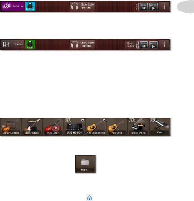
In Monitor Mode, the Main Toolbar includes buttons for FX To Monitors, Encoder Assign, Show Solo Buttons, Quick Capture and Info.
Perform Mode
In Perform Mode, the Main Toolbar includes buttons for Scenes, Encoder Assign, Show Solo and Show Faders Buttons, Quick Capture and Info.
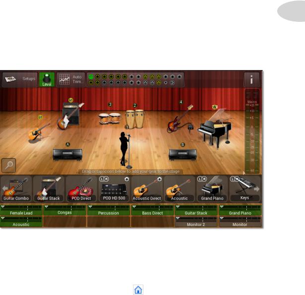
Stage Icon Gallery
The Stage Icon Gallery, visible inSetup Mode, is the horizontal strip of gear icons at the base of the stage. It includes a collection of commonly used gear items, which in addition to providing a visual representation of your onstage gear, establishes powerful audio processing settings for each preset, to ensure each channel will sound as good as if it were mixed by a professional live sound engineer.
Swipe the Stage Icon Gallery to the left or right to see more Stage Icons. At the far right you’ll see a More folder icon, which provides access to the completePreset Library.
See the Setup Mode chapter for more details on the Stage Icon Gallery.

M20d Overview
Controller Strips
1•6 |
The Controller Strips are located at the base of the stage. They display individual channel |
||
information such as Channel Name, Channel Icon, Fader Level, Output Level and Mute or Solo |
|||
|
|||
|
state, as illustrated below in Perform Mode or Record Mode. |
|
|
|
|
Level Fader |
|
|
Channel Output Meter |
Channel Name |
|
|
|
||
|
Channel Icon |
Mute Button |
|
|
|
||
In Monitor Mode, the Controller Strips are blue and theMute button is replaced by aLinked/ Unlinked button. See theMonitor Mode chapter for more details.
In Setup Mode the Controller Strips are half height and display only Channel Name, Fader Level and Output Level. Each controller strip is matched to a color-coded M20d hardware encoder, which usually controls level, depending on the currentEncoder Assign selection.
Contextual Browsers
When various buttons are tapped in the M20d user interface, contextual windows may be displayed on the screen. For example, when a Stage Icon is selected in Setup Mode, theEdit Selection buttons will slide into view on the Main Toolbar.
M20d Overview
Tap the Channel Icon button, and theEdit Preset Properties window will be displayed.
1•7
Tap the Icon image, as indicated below, and the Select New Icon Image window will open, where you can browse various icons to replace the current one.
.
You can also rename the channel from this window by tapping the Name field, causing an onscreen text keyboard to appear.
Similar contextual windows will be displayed for Setups and Auto Trim in Setup Mode, Scenes in Perform Mode, Configure Record/Playback in Record Mode, Edit Preset Properties and Load/ Save Presets in Tweak Mode, among others.

M20d Overview
Hardware Encoders
1•8 |
The 12 Hardware Encoders make it easy to adjust various software parameters displayed |
|
on the M20d touchscreen. They are color-coded in each case, and are matched up with |
||
|
||
|
specific parameters depending on the current view and encoder assignment. |
|
|
For example, in Setup and Perform mode they can control Channel Level, Trim, Pan |
|
|
or FX Send. In Deep Tweak mode, encoders #1 and #7 control Pan and Level, and if |
|
|
an EQ processor is selected, for example, several other encoders light up and control EQ |
|
|
Frequency, Q, Gain, etc. |
|
|
To illustrate, below is a graphic of the 12 encoders as they would be assigned to the EQ 6 |
|
|
processor in Deep Tweak mode, lit up in various colors to match their EQ 6 parameter |
|
|
assignments. |
Pan |
Low Freq |
Low Shelf |
Mid Freq 1 |
Mid Q 1 |
Mid Gain 1 |
100%L ~ 100%R 20Hz ~ 500Hz -15dB ~ +15dB |
20Hz ~ 18kHz |
0.1q ~ 10.0q |
-15dB ~ +15dB |
||
|
|
|
|
|
|
|
Level |
Mid Freq 2 |
Mid Q 2 |
Mid Gain 2 |
|
Off ~ +12dB |
20Hz ~ 18kHz |
0.1q ~ 10.0q -15dB ~ +15dB |

M20d Overview
Observe how encoder #2 is red to match up with Low Frequency, encoder #7 is green to match up with Level, and encoder #10 is yellow to match up with Mid Frequency 2. When an
encoder is not assigned, it will not light up at all, as with encoders #8 and #9. |
1•9 |
|
As you switch M20d modes, you’ll see the encoders changing color in sync with the touchscreen, making for intuitive control of the various parameters in the UI.
Double-click Encoder Features
The following is a list of double-click Encoder features, plus a few other Tips.
Level Encoder - Tweak Mode:
Double-click the Level encoder in Tweak Mode and it sets the Level to 0. This is also true for Global FX Send & Return Level, as well as Monitor Send & Output Level.
Level Encoder - All Other Modes:
Double-click the encoder for any channel in Setup, Record, Monitor or Perform Mode (regardless of Encoder Assignment) and the M20d jumps to Tweak Mode for the selected channel.
Pan Encoder - Tweak Mode:
Double-click the Pan encoder in Tweak Mode and the Pan position is set to center.
Processor Parameter Encoders - Tweak Mode:
Double-click the encoder for any Processor Parameter and the parameter value goes to a default setting (for example, EQ Gain goes to 0dB, HighPass Filter Frequency goes to 75Hz, Comp Output Gain goes to -3dB, etc.).
Perform Button - Hardware:
Double-click the hardwarePerform button in any mode, regardless of Encoder Assignment (could be assigned to Pan, Monitor, Trim or FX, for example) and the M20d jumps to Perform Mode with encoders assigned to Level, for instant mixing mode.
Setup Button - Hardware:
Press and hold the hardwareSetup button to bring up the M20d Startup screen.

M20d Overview
Unassigned Encoder - Create Group:
Double-click an unassigned encoder and theSelect Channels For Group Encoder window will 1•10 open, displaying all channels available for grouping. Tap the channel icons you’d like to include in the Group, name the Group, then tap OK. A Group controller strip will appear in the M20d stage
view, automatically assigned to the hardware encoder you originally double-clicked. *See Page 2•13 for more info on Group Encoder Features.

Setup Mode
Setup Mode
SETUP
When you first power up your StageScape M20d, you will need to set up your inputs, outputs and channel assignments in Setup Mode.
The M20d will power up in Setup Mode, or you can enter Setup Mode at any time by pressing the |
2•1 |
|
|
hardware SETUP button. The touchscreen will display theStage View, the Stage Icon Gallery, |
|
the Controller Strips, and the Main Toolbar, which includes the Setups button, Encoder |
|
Assign button, Auto Trim button, I/O Panel and Info button. |
|
Below is an illustration of the M20d touchscreen in Setup Mode, with one XLR microphone |
|
connected to Input #1. |
|
Creating Input Channels
There are 3 main ways to create Input Channels and configure your outputs and channel assignments: Physical Connections, the Stage Icon Gallery and Setups.

Setup Mode
Using Physical Connections
Plug in the various cables to connect your mic and line inputs, mains and monitor speakers. The M20d will sense an XLR or 1/4 inch jack has been plugged in, and a graphic connector will be displayed on the I/O Panel for each jack, indicating a valid connection.
A default Stage Icon will appear on the stage for each connected input, and a Controller Strip will 2•2 automatically be assigned to it. When all your gear has been plugged in, the stage will be populated
with various default stage icons associated with the physical gear you have connected.
Above is an illustration of a Duo setup with 2 mics, aux and line inputs, monitors and mains.
The next step when connecting your gear in this way would be to customize your stage icons and channel presets to match your physical gear.
See Chapter 10: Setup Examples for more details on setting up your gear using physical connections, using the above Duo setup as an example.
Setup Mode
Using The Stage Icon Gallery
Instead of plugging in your gear first, you can create various input channels using theStage Icon Gallery, which is the horizontal strip of icons displayed just above the controller strips.
Swipe the gallery left or right to reveal all the icons, including theMore folder (seePage 2•15). See the Channel Presets section on Page 2•14 for more detail on managing presets.
2•3
For each input channel you’d like to create, tap or drag an icon from the Stage Icon Gallery, and a controller strip will automatically be assigned to it. You can also tap an icon in the Gallery to replace a selected icon on the stage.
The channel will be loaded with a default Channel Preset, and if there is no physical input connection yet for the selected icon, the associated input graphic on the I/O Panel will be colored dim amber.
Above is an example of a stage setup created entirely by using the Stage Icon Gallery, with only one XLR cable plugged in for the Female Vocal in Channel #1. Inputs 2 through 8 on the I/O Panel are colored dim amber, as are the monitor and mains jacks.
Setup Mode
The next step when configuring your setup using the Stage Icon Gallery would be to plug in the various cables to connect your gear as depicted on the M20d stage, at which time their I/O Panel connectors will be colored green.
Using Setups
The third way to set up your M20d inputs, outputs and channel assignments is to load aSetup. 2•4 A Setup is defined as the current configuration of all M20d inputs and outputs, all FX and channel settings, levels, mutes, pans, monitor send levels, footswitch assignments, L6 LINK settings and
your stage icon layout.
The most recent Setup is persistent in M20d internal memory, and it will automatically be loaded at power up. So if you’ve previously configured your M20d, your Setup at power up will be exactly as you left it during your last session.
And if you’ve previously saved one or more Setups, you can recall and load any one of them by tapping the Setups button in the Main Toolbar. (SeePage 2•9 for more details on saving and loading Setups).
All I/O Panel graphic jacks in the Setup will be assigned as you last saved them, and will be displayed as either amber (if not yet connected) or green (if connected). Your previous stage icons and channel names will also be retained.
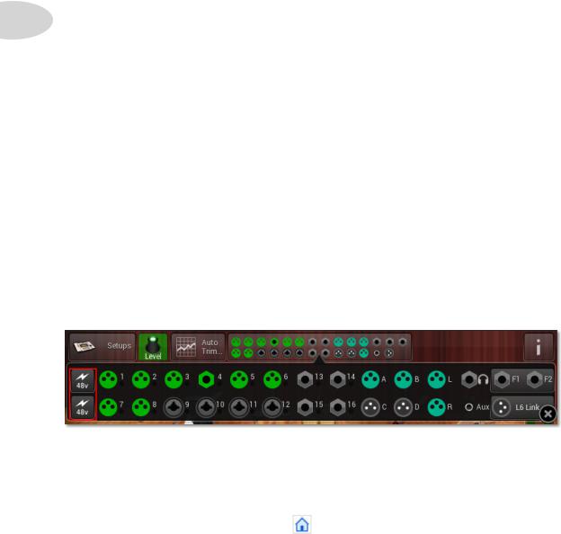
I/O Panel
The I/O Panel in Setup Mode is essentially a mirror image of the physical M20d’s I/O Panel. It displays all your input and output connections and enables you to swap them around, if needed, via the touchscreen UI.
To zoom in on the I/O Panel just tap it in the Main Toolbar. This gives you access to the +48V buttons.

Setup Mode
+48 V Buttons
When using condenser microphones, you may need +48V power. The M20d provides this via the +48V power buttons when you zoom in on the I/O Panel. The top +48V button powers the top row of Mic inputs, and the bottom +48V button powers the bottom row.
I/O Reassignment |
2•5 |
|
On occassion you may find that you need to reassign an instrument to a different input, or a stage |
||
monitor to a different output. Suppose you have ideal channel settings for Input 1 prior to connecting |
|
|
any microphones or instruments to the M20d, and it happens that the instrument intended for Input |
|
|
1 has been connected to Input 4. You may be inclined to swap the physical connections of inputs |
|
|
1 and 4, but that may prove to be impractical in a critical live performance scenario. |
|
|
In a situation like this the M20d provides I/O Reassignment, using the touchscreen UI. This feature |
|
|
is also accessible remotely using the free StageScape Remote app for iPad®. |
|
|
To reassign jacks in Setup Mode using the virtual I/O Panel, follow these steps: |
|
|
1. |
Select the Stage Icon for the input assignment you wish to reassign. |
|
2. |
Tap the I/O Panel in the Main Toolbar to zoom in on it. |
|
3. |
The selected Stage Icon’s current input jack will be highlighted. |
|
4. |
Tap the input jack to which you wish to assign the selected Stage Icon. |
|
5. |
The selected Stage Icon’s input jack is now the jack you tapped in Step 4. |
|
Note: only presets with the 1/4” badge can be swapped or assigned to Inputs 13-16.
Tip: If you tap an input jack to which another channel is already assigned, the inputs of that channel and the currently selected channel will be swapped.
Tip: You can also reassign outputs for Monitors A-D using this operation.
Setup Mode
|
Customizing Stage Icons |
|
When you’d like to change the appearance of a stage icon and retain its channel settings, this is |
|
easily accomplished by using theEdit Selection button in theMain Toolbar. |
|
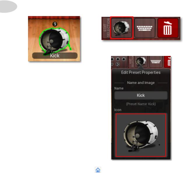
For example, let’s say you have a Kick drum stage icon and you’d like it to represent a full drum set. |
2•6 |
First tap the Kick stage icon to select it. Then tap theEdit Selection Icon in theMain Toolbar. |
The Edit Preset Properties window will open.
Tap the Kick’s Icon image to select it.
Setup Mode
The Select New Icon Image browser will open. Select theDrums category, then tap the Drum Set icon.
2•7
Tap the blue OK button.
This replaces the Kick icon with the Drum Set icon, which will now be displayed on the stage.
For more details on customizing Stage Icons, seeChapter 10: Setup Examples.

Setup Mode
|
Resizing Stage Icons |
|
If you find that you have quite a few stage icons on your stage, you may want to make them a little |
|
smaller. Or if you have a low channel count, you may want to make them a little larger. |
|
With the Resize Slider, it’s easy to resize your stage icons, as follows. |
2•8 |
To resize a single Stage Icon: |
|
If you’d like to resize your stage icons one at a time, follow these steps: |
•In Setup Mode, select the Stage Icon you wish to resize.
•Press the Resize button in the bottom-left of the Stage View.
•Drag the popup Resize Slider left or right to decrease or increase the icon’s size.
•Click anywhere on the stage to dismiss the Resize slider.

Setup Mode
To resize all Stage Icons simultaneously:
If you’d like to resize all the stage icons on your stage at the same time, follow these steps:
2•9
•In Setup Mode, select the Stage View background so that no Stage Icon is selected.
•Press the Resize button in the bottom-left of the Stage View.
•Drag the popup Resize Slider left or right to decrease or increase the size of all Stage Icons.
•Click anywhere on the stage to dismiss the Resize slider.
Auto Trim
The Auto Trim feature optimizes a channel’s input level by quickly analyzing it, then setting the new trim level automatically. This ensures that you always have the best possible input level while guarding against channel distortion.
To use Auto Trim, tap theAuto Trim button in the Main Toolbar.
This will cause the Auto Trim window to open.

Setup Mode
Tap the icon of the channel you’d like to optimize - in this example, Female Lead is selected.
2•10
Tap the Start Analysis button while performing at your loudest level. Auto Trim will analyze the input level, displaying an activity graphic over the channel icon. After a few seconds, any needed trim adjustment will be displayed in dB.
Auto Trim will analyze the input level and display an activity graphic over the channel icon. After a few seconds, any needed trim adjustment will be displayed in dB.
To apply the new optimized trim level to the channel, tap the blueConfirm Changes button.
Setup Mode
Saving & Loading Setups
A Setup is analogous to the collection of gear you would bring to a live show, as well as your M20d’s channel information. This may include vocal mics, guitars, a bass rig, drum kit, digital keyboard and perhaps an MP3 player or laptop computer. Additionally, you may be responsible for providing your own stage monitors and front of house speakers.
2•11
AnM20dSetup,asmentionedonPage 2•4,isdefinedasthecurrentconfigurationofallyourinputs and outputs, FX and channel settings, levels, mutes, pans, monitor levels, footswitch assignments, L6 LINK settings and your stage icon layout, which represents your onstage gear.
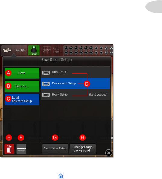
To save, load, rename, delete or create a new Setup, tap the Setups button in the Main Toolbar. The Save & Load Setups window will open, as illustrated below.
The following page describes the Setup functions that can be performed from this window.

Setup Mode
Save & Load Setups Functions
A.Save the current Setup. Tap this button to save the current configuration. Since “Rock Setup” is the last loaded Setup, any changes made will be saved to “Rock Setup”.
B.Save the current configuration as a new Setup. Tap this button and the text keyboard window will open. You can then name the current Setup and save it.
2•12
C. Load the selected Setup. In this example, the “Percussion Setup” is selected in the Setups list (D), so “Percussion Setup” would be loaded when tapping this button.
D. This is the Setups List. It includes all the Setups you currently have saved in the M20d’s internal memory.
E. Delete the selected Setup. When you tap the Delete button, a confirmation dialog will be displayed to confirm deleting the currently selected Setup in the Setups list (D).
F. Rename the selected Setup. Tap the Rename button and the text keyboard window will open. You can then rename the currently selected Setup in the Setups list (D).
G. Create New Setup. Tap this button and a new Setup with no stage icons will be created, replacing the current Setup. You can save changes before you commit.
H. Change Stage Background. Tap this button and theChange Stage Background browser will be displayed. Browse to select a new stage background - tapLoad Stage to display it.

Setup Mode
Group Encoders
From time to time it may be useful to create a Group encoder. For example, if you wanted to group three background vocal channels together, or a rhythm section, once you had a good balance it would be convenient to raise or lower all 3 channels with one encoder.
To create a Group encoder, double-press any unassigned hardware encoder. The Select |
2•13 |
Channels For Group Encoder window will open, displaying all channels available for grouping. |
|
Tap the channel icons you’d like to include in the Group, which would be the Bass, Guitar and Piano in the above example. Name the Group in theGroup Name field, then tap the blueOK button.
A Group controller strip will appear in the M20d stage view, automatically assigned to the hardware encoder you originally double-pressed. Now you can adjust all 3 channels with the one Group encoder.

Setup Mode
|
Channel Presets Overview |
|
The M20d characterizes each input and output connection as a channel. Channels are visually |
|
stylized as recognizable gear, referred to as Stage Icons, which you can select from the Stage Icon |
|
Gallery. |
2•14 |
With the M20d, a Channel Preset is the collection of properties that define a channel. This includes |
its icon image, name, input or output jack assignment and its signal processing settings. Each item within the Stage Icon Gallery represents a Channel Preset. Note that while the M20d provides hundreds of Channel Presets to meet almost any live sound need, you can customize every aspect of a channel and store your own personalized Channel Presets.
Managing Stage Icons within the Stage Icon Gallery
If you find that the Stage Icon Gallery provides more Stage Icons than you will ever need, you may wish to remove some of them. On the other hand, you may wish to add icons. Additionally, it is possible to mark icons that you use frequently as “Favorites”.
To remove an item from the Stage Icon Gallery:
1. In the Stage Icon Gallery, Press+Hold the Stage Icon you wish to remove.
Wait for the item’s context menu to appear
2. From the context menu, tap theRemove from Gallery button
You will observe that the icon is removed from the gallery.
Note: This operation does not permanently remove the item from StageScape’s preset library.
To mark an item as a “Favorite” within the Stage
Icon Gallery:
Repeat the above steps, but this time tap the Mark as
Favorite button in Step 3.
You will observe that a yellow star appears adjacent to the
Favorite icon within the gallery.

|
Setup Mode |
Accessing the complete Preset Library via the ‘More... |
’ Icon |
The Stage Icon Gallery provides easy access to Channel Presets for the most common types of |
|
input and output devices required in live sound. However, presets referenced within the Icon Gallery |
|
represent only a fraction of all the presets available to you. The last item in the Stage Icon Gallery is |
|
a folder icon labeled, “More...”, which contains the entire library of Channel Presets. |
|
To access the complete Channel Preset Library: |
2•15 |
Scroll to the end of the Stage Icon Gallery, so that you see theMore... icon. Tap it.
The Preset Library dialog will appear over the Stage View.
The P
The Preset Library dialog allows you to add any of its presets to the Stage View, as well as replace the preset of any Stage Icon on the stage.
The P the pr

Setup Mode
|
To add a new icon to the Stage View from the Preset Library dialog: |
|
|
1. |
Select a preset category using theCategory menu located in the top-right of the dialog. |
|
2. |
Select a preset from the preset list in the right side of the dialog. |
|
3. |
Tap Add To Stage. |
2•16 |
You will observe that the dialog is dismissed and the Stage Icon for the selected preset appears on |
|
the stage. |
||
To replace a Stage Icon’s preset from the Preset Library dialog:
1.In the Stage View, select the Stage Icon whose preset you wish to replace.
2.Select a preset category using theCategory menu located in the top-right of the dialog.
3.Select a preset from the preset list in the right side of the dialog.
4.Tap Load Selected.
Observe that the dialog is dismissed and the selected Stage Icon’s channel preset is replaced.
Tip: Note that the M20d retains the channel’s image and name if you had modified the image or name prior to selecting a new preset.
Include Master FX
When loading a new preset, the M20d provides the option of including the preset’sMaster FX settings. This is useful for loading Channel Presets that were designed with specific Master FX settings in place, such as “Female w/Reverb” and “Male Doubled”.
To include Master FX when replacing a Stage Icon’s preset from the Preset Library dialog:
1.Enable the Include Master FX option
2.Select a preset from the preset list
3.Tap Load Selected
Important: Be aware that Master FX are global, meaning their settings affect all channels using Master FX.
Loading...