


LeicaDM5500B
LeicaDM6000B
LeicaDM6000M
Operating Manual
Bedienungsanleitung
Manuel d’utilisation
1

Published September 2007 by:
Herausgegeben September 2007 von:
Publié en septembre 2007 par :
Leica Microsystems CMS GmbH
Ernst-Leitz-Straße
D-35578 Wetzlar (Germany)
Responsible for contents:
Verantwortlich für den Inhalt:
Responsable du contenu :
Dr. Jasna Roeth, Stefan Motyka
(Product manager „Life Science Research“) (Produktmanager „Life Science Research“) (Chef de produit „Life Science Research“)
Holger Grasse
(Safety Officer according to MPG §30) (Sicherheitsbeauftragter nach MPG §30) (Officier de sécurité selon MPG §30)
In case of questions, please contact the hotline: Bei Fragen wenden Sie sich bitte an die Hotline: Pour toute question, contacter l’assistance en ligne:
|
|
|
|
Phone |
+49(0) 64 41-29 22 86 |
|
|
Fax |
+49(0) 64 41-29 22 55 |
|
|
E-Mail: |
MQM-Hotline@leica-microsystems.com |
||
2
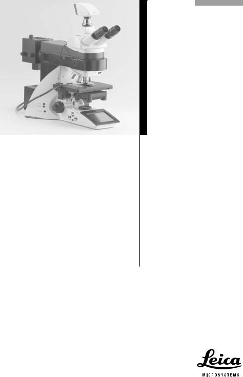
Leica DM5500B
Leica DM6000B
Leica DM6000M
Operating Manual
3

Copyrights
Copyrights
All rights to this documentation are held by Leica Microsystems CMS GmbH. Reproduction of text or illustrations (in whole or in part) by print, photocopy, microfilm or other method (including electronic systems) is not allowed without express written permission from Leica Microsystems CMS GmbH.
The term "Windows" can be used in the following text without further identification. It is a registered trademark of the Microsoft Corporation. Otherwise, no inference with regard to the free usability of product names may be drawn from the use of those names.
The instructions contained in the following documentation reflect state-of-the-art technology and knowledge standards. We have compiled the texts and illustrations as accurately as possible. Nevertheless, no liability of any kind may be assumed for the accuracy of this manual’s contents. Still, we are always grateful for comments and suggestions regarding potential mistakes within this documentation.
The information in this manual is subject to modification at any time and without notification.
4

Contents
Contents
1. |
Important Notes about this Manual ...... |
7 |
7. |
Startup ......................................................... |
39 |
|
|
|
|
7.1 |
Functional Principle .................................. |
39 |
|
2. |
Intended Purpose of Microscopes ........ |
8 |
7.2 |
Switching on ............................................... |
46 |
|
|
|
|
7.3 |
The Leica SmartTouch .............................. |
47 |
|
3. |
Safety Notes ............................................... |
9 |
7.4 |
The Function Keys at the stand .............. |
48 |
|
3.1 |
General Safety Notes ............................... |
9 |
7.5 |
The Remote Control Element |
|
|
3.2 |
Electrical Safety ........................................ |
10 |
|
SmartMove ................................................. |
49 |
|
3.3 |
Disposal ....................................................... |
11 |
7.6 |
Köhler Illumination .................................... |
49 |
|
|
|
|
|
7.6.1 |
Transmitted Light ............................ |
49 |
4. |
Overview of the Instrument .................... |
12 |
|
7.6.2 |
Incident Light ................................... |
51 |
|
|
|
7.7 |
Checking Phase Contrast Rings ............. |
52 |
|
5. |
Unpacking the Microscope .................... |
18 |
7.8 |
Adjusting Motorized Polarizer ................ |
54 |
|
|
|
|
7.9 |
Adjusting the Light Sources .................... |
54 |
|
6. |
Assembling the Microscope .................. |
20 |
|
|
|
|
6.1 |
Stage ............................................................ |
21 |
8. |
Operation .................................................... |
60 |
|
6.2 |
Condenser ................................................... |
22 |
8.1 |
Switching on ............................................... |
60 |
|
6.3 |
Tube and Eyepieces .................................. |
23 |
8.2 |
Stages and Specimen Displacement .... |
62 |
|
6.4 |
Objectives ................................................... |
24 |
|
8.2.1 Manual stage (DM5500 B) ............ |
62 |
|
6.5 |
Light Sources for the |
|
|
8.2.2 Motorized stage (DM6000 B/M) ... |
63 |
|
|
Transmitted Light Axis .............................. |
24 |
8.3 |
Focusing ...................................................... |
64 |
|
6.6 |
Light Sources for the |
|
8.4 |
Tubes ........................................................... |
65 |
|
|
Incident Light Axis ..................................... |
26 |
8.5 |
Eyepieces .................................................... |
67 |
|
|
6.6.1 106 z lamp housing ......................... |
26 |
8.6 |
Objectives ................................................... |
67 |
|
|
6.6.2 External light source EL6000 ........ |
31 |
8.7 |
Magnification Changer ............................. |
70 |
|
6.7 |
Equipping the |
|
8.8 |
Light Sources ............................................. |
70 |
|
|
Incident Light Turret Disc ........................ |
32 |
8.9 |
Aperture Diaphragm and |
|
|
6.8 |
Polarizer and Analyzer ............................. |
33 |
|
Field Diaphragm ......................................... |
71 |
|
6.9 |
DIC Prisms .................................................. |
34 |
|
|
|
|
6.10 |
Optional Accessories ............................... |
35 |
|
|
|
|
6.11 |
Connecting the Leica CTR5500/CTR6000 |
|
|
|
|
|
|
Electronics Box .......................................... |
37 |
|
|
|
|
6.12 |
Connecting the Computer ........................ |
38 |
|
|
|
|
6.13 |
Connection to the Power Supply ............ |
38 |
|
|
|
|
5

Contents
9. |
Contrasting Methods for |
|
11. |
Trouble Shooting ....................................... |
82 |
|
|
Leica DM5500 B and DM6000 B ............. |
72 |
|
|
|
|
9.1 |
Transmitted Light ....................................... |
72 |
12. |
Care of the Microscope ........................... |
85 |
|
|
9.1.1 |
Bright Field ....................................... |
72 |
12.1 |
Dust Cover .................................................. |
85 |
|
9.1.2 |
Phase Contrast ................................ |
73 |
12.2 |
Cleaning ....................................................... |
85 |
|
9.1.3 |
Dark Field ......................................... |
73 |
12.3 |
Handling Acids and Bases ...................... |
86 |
|
9.1.4 |
Polarization ...................................... |
74 |
|
|
|
|
9.1.5 |
Differential Interference Contrast .. |
75 |
13. |
Essential Wear and Spare Parts ............ |
87 |
9.2 |
Fluorescence .............................................. |
76 |
|
|
|
|
9.3 |
Combi Mode ............................................... |
77 |
14. |
Abbreviations and Pictograms .............. |
88 |
|
10. |
Contrasting Methods for |
|
15. |
Index ............................................................ |
90 |
|
|
Leica DM6000 M ........................................ |
78 |
|
|
|
|
10.1 |
Incident Light ............................................. |
78 |
16. |
EU Declaration of Conformity ................. |
91 |
|
|
10.1.1 Bright Field ....................................... |
78 |
|
|
|
|
|
10.1.2 Dark Field ......................................... |
78 |
|
|
|
|
|
10.1.3 Polarization ...................................... |
79 |
|
|
|
|
|
10.1.4 Interference Contrast .................... |
80 |
|
|
|
|
|
10.1.5 Fluorescence ................................... |
80 |
|
|
|
|
10.2 |
Transmitted Light ....................................... |
81 |
|
|
|
|
|
10.2.1 Bright Field ....................................... |
81 |
|
|
|
|
|
10.2.2 Polarization ...................................... |
81 |
|
|
|
|
6
1. Important Notes about this Manual
1. Important Notes about this Manual
Caution!
This operating manual is an essential component of the microscope, and must be read carefully before the microscope is assembled, put into operation or used.
Text symbols, pictograms and their meanings:
(1.2)
→p.20
!
*
This operating manual contains important instructions and information for the operational safety and maintenance of the microscope and accessories. Therefore, it must be kept and taken care of.
For the operation of the LeicaScreen and the Leica Application Suite (LAS), please see separate operating manual.
Numbers in parentheses, such as "(1.2)", correspond to illustrations (in the example, Figure 1, Item 2).
Numbers with pointer arrows (for example → p.20), point to a certain page of this manual.
Caution!
Special safety instructions within this manual are indicated with the triangle symbol shown here, and have a gray background.
Caution! The microscope and accessories can be damaged when operated incorrectly.
Notes on how to dispose of the microscope, its components and expendables.
Explanatory note.
Item not contained in all configurations (optional).
7
2. Intended Purpose of Microscopes
2. Intended Purpose of Microscopes
The Leica DM5500 B and DM6000 B microscopes, to which this user manual belongs, are designed for biological routine and research applications. This includes the examination of samples taken from the human body with a view to providing information on physiological or pathological states or congenital abnormalities, or to determining the safety and compatibility with potential recipients, or to monitoring therapeutic measures.
The Leica DM6000 M microscope is designed for examinations in the field of materials research.
All the above-named microscopes comply with the Council Directive 98/79/EEC concerning in vitro diagnostics. They also conform to the Council Directives 73/23/EEC concerning electrical apparatus and 89/336/EEC concerning electromagnetic compatibility for use in an industrial environment.
Caution!
The manufacturer assumes no liability for damage caused by, or any risks arising from using the microscopes for other purposes than those for which they are intended or not using them within the specifications of Leica Microsystems CMS GmbH.
In such cases the conformity declaration shall cease to be valid.
Caution!
These (IVD) devices are not intended for use in the patient environment defined by DIN VDE 0100-710. Neither are they intended for combining with medical devices according to EN 60601-1. If a microscope is electrically connected to a medical device according to EN 60601-1, the requirements defined in EN 60601-1-1 shall apply.
8

3. Safety Notes
3. Safety Notes
3.1 General Safety Notes
This safety class 1 device is constructed and tested in accordance with
EN 61010-2-101:2002, EN 61010-1:2001, IEC 1010-1:2001,
safety regulations for electrical measuring, control, and laboratory devices.
Caution!
In order to maintain this condition and to ensure safe operation, the user must follow the instructions and warnings contained in this operating manual.
Caution!
The devices and accessories described in this operating manual have been tested for safety and potential hazards.
The responsible Leica affiliate or the main plant in Wetzlar must be consulted whenever the device is altered, modified or used in conjunction with non-Leica components that are outside of the scope of this manual.
Unauthorized alterations to the device or noncompliant use shall void all rights to any warranty claims!
9

3. Safety Notes
3.2 Electrical Safety General specifications
Leica CTR5500 and CTR6000 electronics box
For indoor use only. |
|
Supply voltage: |
90-250 V~ |
Frequency: |
50-60 Hz |
Power input: |
max. 290 VA |
Fuses: |
T6,3 A |
Ambient temperature: |
(IEC 60127-2/3) |
15-35°C |
|
Relative humidity: |
max. 80% to 30°C |
Overvoltage category: |
II |
Pollution degree: |
2 |
Microscope |
|
For indoor use only. |
|
Supply voltage: |
90-250 V~ |
Frequency: |
50-60 Hz |
Power input: |
See CTR5500/6000 |
Fuses: |
See CTR5500/6000 |
Ambient temperature: |
15-35°C |
Relative humidity: |
max. 80% to 30°C |
Overvoltage category: |
II |
Pollution degree: |
2 |
Supply unit ebq 100* |
|
For indoor use only. |
|
Supply voltage: |
90-250 V~ |
Frequency: |
50-60 Hz |
Power input: |
max. 155 VA |
Fuses: |
2xT2A (IEC 127) |
Ambient temperature: |
10-36°C |
Relative humidity: |
max. 80% to 30°C |
Overvoltage category: |
II |
Pollution degree: |
2 |
(see enclosed manual) |
|
Leica EL6000
For indoor use only. Supply voltage: Frequency:
Power consumption: Fuses:
Ambient temperature: Relative humidity:
Overvoltage category: Contamination class: (see enclosed manual)
100-240 V~ (±10%)
50-60 Hz max. 210 VA
5x20, 2.5 A, slow, breaking capacity H → EL6000 manual 0°-40°C
10-90% non-condensing II
2
Caution!
The power plug may only be plugged into an outlet equipped with a grounding contact.
Do not interfere with the grounding function by using an extension cord without a ground wire. Any interruption of the ground wire inside or outside of the device, or release of the ground wire connection, can cause the device to become hazardous. Intentional ground interruption is not permitted!
10
3. Safety Notes
Caution!
Through activating to the grounding connection (earth screw on the back of the Leica CTR5500 and CTR6000 Electronics Box) ancillary equipment with its own and/or extra power supply may be brought to the same ground wire potential. For connections without a ground connector, Leica Service must be consulted.
Caution!
Never use any fuses as replacements other than those of the types and the current ratings listed here. Using patched fuses or bridging the fuse holder is not permitted.
Caution!
The microscope’s electrical accessory components are not protected against water. Water can cause electric shock.
Caution!
Protect the microscope from excessive temperature fluctuations. Such fluctuations can lead to the accumulation of condensation, which can damage the electrical and optical components.
Ambient temperature: 15-35°C.
Caution!
Before exchanging the fuses or lamps, be absolutely certain to switch-off the main power switch and remove the power cable.
Caution!
Touch the touchscreen using your finger only. Never use a pen or other hard, sharp or pointed objects.
3.3 Disposal
After the end of the product’s life, please contact Leica Service or Leica Sales on how to dispose of it.
Please observe the national laws and ordinances which, for example, implement and ensure compliance with EU directive WEEE.
n.b.:
Like all electronic instruments, the microscope, its components and expendables may not be disposed of as general household waste!
11

4. Overview of the Instrument
4. Overview of the Instrument
Specification |
Leica DM5500 B/DM6000 B |
Leica DM6000 M |
|||||
|
|
|
|
|
|||
Contrasting Method |
• |
transmitted light: |
• |
transmitted light: BF, Pol |
|||
|
|
BF, DF, PH, ICT (DIC), Pol |
• |
incident light: |
|||
|
• |
incident light: Fluo |
|
BF, DF, ICR (DIC), Pol, Fluo |
|||
|
|
|
|
|
|||
Transmitted Light Axis |
|
• |
automatic Illumination Manager |
||||
|
|
|
(automatic aperture diaphragm and field diaphragm, |
||||
|
|
|
automatic intensity control) |
|
|||
|
|
• |
automatic Constant Color Intensity Control (CCIC) |
||||
|
|
• |
motorized shutter |
|
|
||
|
|
|
|
||||
Incident Light Axis |
• |
integrated into the stand |
• integrated into the stand |
||||
|
• motorized 8x filter turret |
• motorized 4x filter turret |
|||||
|
|
( 5x optional) |
|
(2 fixed positions, 2 variable |
|||
|
• with FIM |
(Fluorescence In- |
|
positions) |
|||
|
|
tensity Manager) for de- |
• |
automatic Illumination |
|||
|
|
creasing light intensity in 5 |
|
Manager |
|||
|
|
steps |
|
|
|
• |
motorized shutter |
|
• |
mechanical “Booster Lens“ |
|
(speed < 0.1 s) |
|||
|
|
for increasing fluorescence |
|
|
|||
|
|
intensity |
|
|
|
|
|
|
• motorized |
Excitation Man- |
|
|
|||
|
|
ager to control the fluores- |
|
|
|||
|
|
cence emission when using |
|
|
|||
|
|
double and triple filter cubes |
|
|
|||
|
|
(optional). |
|
|
|
||
|
• |
ultra-fast, internal filter |
|
|
|||
|
|
wheel |
|
(IFW), motorized |
|
|
|
|
|
(optional) |
|
|
|
||
|
• |
motorized shutter |
|
|
|||
|
|
(speed < 0.1 s) |
|
|
|||
|
|
|
|
|
|
|
|
Tube |
|
|
• |
motorized or manual |
|
|
|
|
|
|
• |
up to 3 beam splitting positions |
|||
|
|
|
• |
optionally with two camera outputs |
|||
|
|
|
|
(for one digital and e.g. one analog camera) |
|||
|
|
|
|
|
|
|
|
12

4. Overview of the Instrument
Specification |
Leica DM5500 B/DM6000 B |
Leica DM6000 M |
|||
|
|
|
|
|
|
Magnification Changer |
• |
manual |
|
• |
manual |
(optional) |
• |
absolute coded |
• |
absolute coded |
|
|
• |
magnification steps: |
• |
magnification steps: |
|
|
|
1x; 1.25x; 1.6x |
|
1x; 1.5x; 2x |
|
|
|
|
|
|
|
Objective Turret |
• |
DM6000 B: motorized |
• |
motorized |
|
|
|
DM5500 B: manual |
• |
absolute coded |
|
|
• |
absolute coded |
• 6x for objectives with M32 |
||
|
• |
7x for |
objectives with M25 |
|
thread |
|
|
thread |
|
• mot. DIC objective prism |
|
|
• |
mot. DIC objective prism tur- |
|
turret with 4 positions |
|
|
|
ret with 4 positions |
|
(optional) |
|
|
|
(optional) |
|
|
|
|
|
|
|
|
|
X/Y Stage |
|
• |
DM6000 B/M: motorized, direct stepper motor drive |
||
|
|
|
DM5500 B: manual |
|
|
|
|
• |
replaceable specimen stage |
||
|
|
• |
zero position defined by end switch |
||
|
|
• |
outer dimensions: 234 mm x 157 mm |
||
|
|
• |
travel range: 76 mm x 50 mm |
||
|
|
• smallest increment: 0.3 m |
|
||
|
|
|
|
|
|
Condenser |
|
• |
motorized condenser head |
|
|
|
|
• |
automatic change between contrasting methods: |
||
|
|
|
motorized condenser turret for light rings, DF stop, |
||
|
|
|
DIC prisms |
|
|
|
|
• optional polarizer integrated and motorized |
|||
|
|
• |
automatic Köhler Illumination |
||
|
|
|
|
|
|
Z Drive |
|
• |
motorized |
|
|
|
|
• |
dovetail for exchanging stage |
||
|
|
• |
travel range: 25 mm |
|
|
|
|
• |
smallest increment: 0.015 m |
||
|
|
• max. speed: 5 mm/s |
|
|
|
|
|
• min. speed: 1 mm/s |
|
|
|
|
|
• |
max. load: 4 kg |
|
|
|
|
|
|
|
|
13

4. Overview of the Instrument
Specification |
Leica DM5500 B/DM6000 B |
Leica DM6000 M |
||
|
|
|
|
|
Control Panels |
• |
Function keys at the stand |
||
|
• additional variable function keys |
|||
|
• |
focusing knobs |
|
|
|
• |
Leica SmartTouch: touch sensitive LC display |
||
|
• |
SmartMove: ergonomic control element |
||
|
|
for x,y,z control with additional variable function keys |
||
|
• |
Leica STP6000: ergonomic control element for x,y,z |
||
|
|
control with 11 additional variable function keys |
||
|
|
and touch sensitive LC display |
||
|
|
|
|
|
Leica CTR5500 |
• |
separate control unit to control |
||
Leica CTR6000 |
|
• |
z-drive |
|
Electronics Box |
|
• |
xy-stage (CTR6000) |
|
|
|
• |
objective turret (CTR6000) |
|
|
|
with: |
|
|
|
|
• |
supply voltage for 100W halogen lamp |
|
|
|
• |
supply voltage for SmartMove |
|
|
See → p.10 (electrical safety)) |
|||
|
|
|
|
|
Computer Interface |
• |
USB 2.0 |
|
|
|
|
|
||
Software Tools |
• |
Leica Application Suite (LAS) |
||
|
|
for WindowsTM 2000, XP, Vista |
||
|
• |
for: |
|
|
|
|
• |
microscope and camera configuration |
|
|
|
• |
microscope and camera control |
|
|
|
• |
image recording and image storing |
|
|
|
|
|
|
14
|
|
|
|
|
|
|
|
|
|
|
|
|
|
|
|
|
|
|
|
|
|
|
|
|
|
|
|
|
|
|
|
|
|
|
|
4. Overview of the Instrument |
|
|
|
|
|
|
|
|
|
|
|
|
|
|
|
|
|
|||
|
|
1 |
|
|
|
|
|
|
|
|
|
|
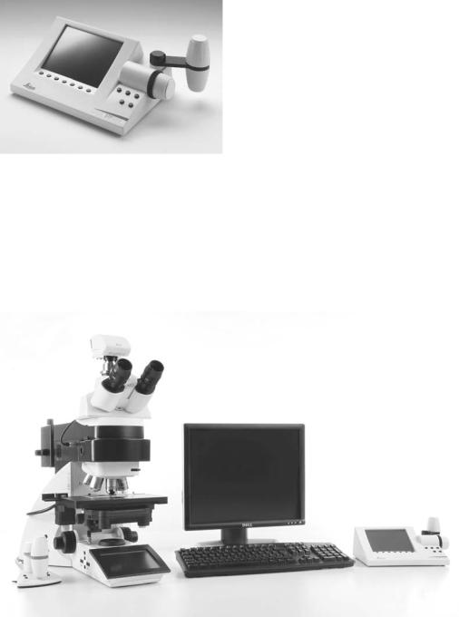
Abb. 1 Control elements of the Leica STP6000 |
|||||
2 |
|
|
|
|
|
|
|
8 |
Touchscreen |
|||||||||
|
|
|
|
|
|
|
|
|
|
|
|
1 |
||||||
|
|
|
|
|
|
|
|
|
|
|
||||||||
|
|
|
|
|
|
|
|
|
|
|
|
|
|
2 |
Information key |
|||
|
|
|
|
|
|
|
|
|
|
|
|
3,4 |
Variable function keys, user-programmable |
|||||
|
|
|
|
|
|
|
|
|
|
|
|
|||||||
|
|
|
|
|
|
|
|
|
|
|
|
5 |
Fine focus adjustment |
|||||
|
|
|
|
|
|
|
|
|
|
|
|
6 |
Coarse focus adjustment |
|||||
|
|
|
|
|
|
|
|
|
|
|
|
7 |
Movement in Y direction |
|||||
|
|
|
|
|
|
|
|
|
|
|
|
|||||||
|
|
|
|
|
|
|
|
|
|
|
|
|
8 |
Movement in X direction |
||||
|
|
|
|
|
|
|
|
|
|
|
|
|
||||||
|
|
|
|
|
|
|
|
|
|
|
|
|
|
|
|
|
|
|
|
|
|
|
|
|
|
|
|
|
|
|
|
|
|
|
|
|
|
|
|
3 |
|
4 |
5 |
6 |
7 |
|
|
|
||||||||
|
|
|
|
|
|
|
|
|
|
|
|
|
|
|
||||
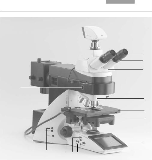
Fig. 1 System overview DM6000 B
15
4. Overview of the Instrument
1
2
3
14
4
5
6
7
|
|
13 |
|
|
|
|
|
|
|
|
|
|
|
|
|
|
|
|
|
12 |
11 |
10 9 |
|
|
||
|
|
|
|
|
||||
Fig. 2 |
Left side of the stand Leica DM6000 B |
|
|
|
|
|
|
|
1 |
Eyepiece |
|
|
8 |
|
Function keys field diaphragm |
||
2 |
Eyepiece tube |
|
|
9 |
|
Transmitted light/incident light switch |
||
3 |
Motorized tube MBDT |
|
|
10 |
|
Function keys aperture diaphragm |
||
4 |
Motorized objective nosepiece with objectives |
|
|
11 |
|
Function keys light intensity |
||
5 |
Motorized specimen stage with specimen holder |
|
|
12 |
|
Focus wheel |
||
6 |
Condenser |
|
|
13 |
|
Variable function keys (factory pre-assigned) |
||
7 |
Leica SmartTouch |
|
|
14 |
|
Lamp adjustment window |
||
n.b.: Illustrations for Leica DM5500 B similar, but with manual objective nosepiece and manual specimen stage
16
4. Overview of the Instrument
15
23
22
21
16
|
|
|
|
|
|
|
|
|
|
|
|
|
|
|
|
|
|
|
|
|
|
|
|
|
|
|
|
|
|
|
|
|
|
|
|
|
|
|
|
|
|
|
|
|
|
|
|
|
|
|
|
|
|
|
|
|
|
|
|
|
|
|
|
|
|
|
|
|
|
|
|
|
|
|
|
|
|
|
|
|
|
|
|
|
|
|
|
|
|
|
|
|
18 |
17 |
|
|
|
|
|
|
|
|||
|
|
|
|
|
20 |
19 |
|
|
|
|
|
|
|
|||||||
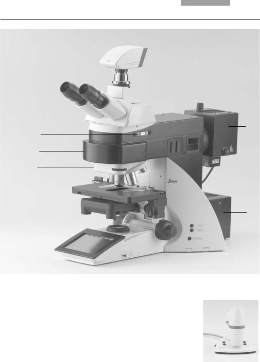
Fig. 3 |
Right side of the stand Leica DM6000 B |
Fig. 4 |
Remote control element SmartMove |
|
|
|
||||||||||||||
15 |
Lamp housing for incident light |
1 |
Movement (x-direction) |
|
|
|
|
|
|
|
|
|
||||||||
16 |
Lamp housing for transmitted light |
2 |
Movement (y-direction) |
3 |
|
|
|
|
|
|
1 |
|||||||||
17 |
Transmitted light filter, optional |
3 |
Focus adjustment |
|
|
|
|
|
|
|
|
|
||||||||
|
|
|
|
|
|
|
|
|
||||||||||||
|
|
|
|
|
|
|
||||||||||||||
18 |
Transmitted light filter, optional |
4 |
Variable function keys |
|
|
|
|
|
|
|
|
|
||||||||
19 |
Variable function keys (factory pre-assigned) |
|
(factory pre-assigned) |
|
|
|
|
|
|
|
|
2 |
||||||||
20 |
Focus wheel |
|
|
|
|
|
|
|
|
|
|
|
|
|
|
|
|
|
||
|
|
|
|
|
|
|
|
|
|
|
|
|
|
|
|
|
||||
21 |
DIC turret |
|
|
|
|
|
|
|
|
|
|
|
|
|
|
|
|
|
|
|
22 |
Motorized filter turret |
|
|
|
|
|
|
|
|
|
4 |
|
|
|
|
|
|
|
||
23 |
Magnification changer |
|
|
|
|
|
|
|
|
|
|
|
|
|
|
|
|
|||
|
|
|
|
|
|
|
|
|
|
|
|
|
|
|
|
|||||
17
5. Unpacking the Microscope
5. Unpacking the Microscope
The device is delivered in several boxes.
The stand box contains the following components:
•Stand with integrated incident light axis and objective nosepiece
•Specimen stage with stage bracket
•Power cable and PC connecting cable
•CD with software package Leica Application Suite (LAS)
•Instructions and list of microscope default settings („Identification Sheet“)
The system box contains the microscope accessories:
•Tube
•Eyepieces
•Objectives
•Condenser
•Lamp housings with accessories
•Fitting tool
•Depending on configuration, additional microscope accessories such as filter cubes, etc.
The Leica CTR5500 or CTR6000 Electronics Box, the remote control element SmartMove, the external ebq 100 supply unit* and the external EL6000 compact light source* are delivered in separate packaging.
First, carefully remove all components from the transportation and packaging materials.
Note:
If at all possible, avoid touching the lens surfaces of the objectives. If fingerprints do appear on the glass surfaces, remove them with a soft leather or linen cloth. Even small traces of finger perspiration can damage the surfaces in a short time. See the chapter, "Care of the Microscope" → p. 85, for additional instructions.
Caution!
Do not yet connect the microscope and peripherals to the power supply at this point!
18

5. Unpacking the Microscope
Installation location
Work with the microscope should be performed in a dust-free room, which is free of oil vapors and other chemical vapors, as well as extreme humidity. At the workplace, large temperature fluctuations, direct sunlight and vibrations should be avoided. These conditions can distort measurements and micrographic images.
Allowable ambient conditions
Temperature |
15-35°C |
Relative humidity |
maximum 80% up to 30°C |
Microscopes in warm and warm-damp climatic zones require special care in order to prevent the build up of fungus.
See the chapter, "Care of the Microscope" → p. 85, for additional instructions.
Caution!
Electrical components must be placed at least 10 cm from the wall and away from flammable substances.
Transport
For shipping or transporting the microscope and its accessory components, the original packaging should be used.
As a precaution to prevent damage from vibrations, the following components should be disassembled and packaged separately:
•Unscrew the objectives.
•Remove the condenser.
•Remove the stage.
•Remove the lamp housings.
•Disassemble the burner of 106 z lamp housing.
•Remove all moving or loose parts.
19

6. Assembly
6. Assembling the Microscope
The microscope components are logically assembled in this order:
•Stage
•Condenser
•Tube
•Eyepieces
•Objectives
•Light sources
•Filter cubes/reflectors*
Only a few commonly used screwdrivers and keys are necessary for assembly, which are included in the delivery package.
When using intermediate systems and optical accessories, the sequence may vary.
In this case, read Chapter
"6.10 Optional accessories" → p. 35.
20
6. Assembly
6.1Stage
!Caution:
Before assembling the stage, make sure no objectives are installed!
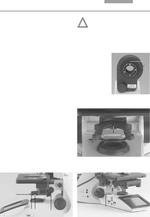
•Place the specimen holder on the stage and fasten it with the two screws (5.1).
•Using the condenser height adjuster (5.2), turn the condenser holder completely upwards, i.e. as close to the stage as possible.
•Loosen the stage clamp (5.3) slightly.
•From above, set the stage clamp onto the dovetail guide (6.2) and push the stage downwards until the upper end of the dovetail guide is tightly fastened to the upper end of the stage clamp.
•Firmly tighten the stage clamp (6.1).
Note:
For thicker specimens (Leica DM6000 M) the stage can be set to a correspondingly lower level.
!Caution:
This changes the pre-set focus position and the lower threshold. Both positions have to be set again. See 8.3. Focusing, → p. 64.
•For the motorized stage only:
Connect the stage cable to the electronics box Leica CTR6000.
See chapter 6.11 → p. 37.
Fig. 5 Object stage (motorized)
1 Locking screws for specimen holder
2 Condenser height adjuster
3 Stage clamp
Fig. 6 Assembling the stage 1 Stage clamp
2 Dovetail guide
1
1
2
23
21
6. Assembly
6.2 Condenser
•Screw the condenser head into the condenser.
•Using the condenser height adjuster (7.4), turn the condenser holder (7.1) completely downwards.
•Unscrew the clamping screw for the condenser (7.3) far enough so that the condenser can be inserted from the front.
•From the front, insert the condenser into the condenser holder as far as it will go. On the underside of the condenser, there is an orientation pin (8.1), which must be located in the guiding notch (9.1).
•Pull the condenser’s clamping screw (7.3) so that the condenser is locked in place.
•Connect the condenser by connecting the condenser cable (10.1) with the stand. The black index point on the stand points to the groove of the plug.
Fig. 7 Condenser holder
1Condenser holder
2Condenser centering
3Clamping screw for condenser
4Condenser height adjuster
Note:
The condenser must be centered before using the microscope.
→ Köhler illumination p. 49.
Fig. 8 |
|
Underside of condenser |
1 |
1 Orientation pin |
Fig. 9 Condenser holder 1 Guiding notch
1
Fig. 10 Condenser connector 1 Condenser cable socket
1
2 |
3 |
1 |
4 |
22
6. Assembly
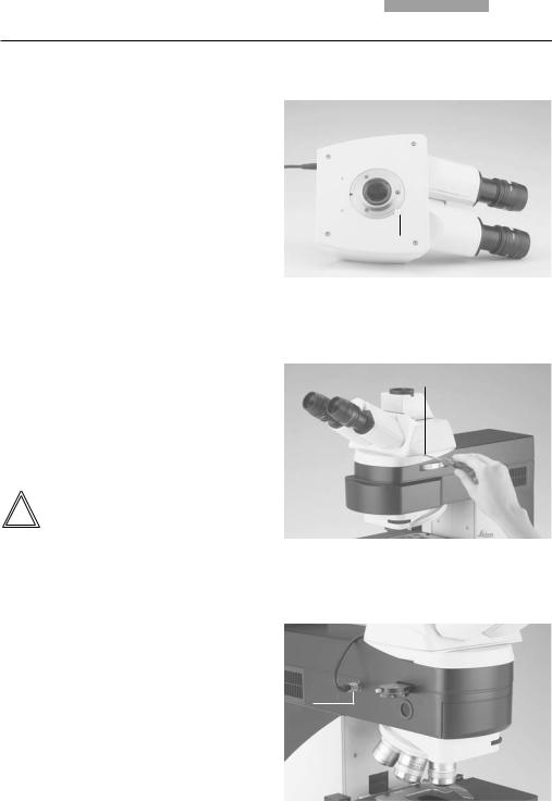
6.3 Tube and Eyepieces
The tube is mounted to the stand either directly or with the use of intermediate modules. It is fastened in place with the side clamping screw (12.1).
•Only for the motorized tube MBDT:
Remove the transportation lock (11.1) from the bottom side of the tube.
•Loosen the clamping screw (12.1). on the stand.
•Insert the tube in the circular receptacle (dovetail ring).
•Retighten the clamping screw (12.1).
•Only for the motorized tube MBDT:
Connect the tube to the stand with the connector socket (13.1).
•The eyepieces are inserted into the eyepiece tubes on the tube.
Note:
Fig. 11 Bottom side of the tube 1 Transportation lock
1
Fig. 12 Fastening the tube 1 Clamping screw
1
For eyepieces that are not included in shipment, we recommend to learn them in with the Software Leica Application Suite (LAS), module: Set-Up. This ensures that the information about total magnification on the LeicaScreen is correct.
Fig. 13 Motorized tube connection 1 Connector socket
1
23
6. Assembly
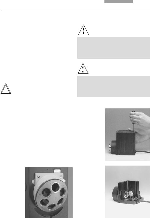
6.4 Objectives
The receptacles on the objective turrets are numbered (Fig. 14). The individual objectives have already pre-assigned positions at the factory according to their configuration.
A list of the exact objective positions is provided in shipment (“Identification Sheet”).
!Caution:
Cover unoccupied threads on the turret with dust protector caps!
Note:
We recommend to perform a parfocality adjustment with the Software Leica Application Suite (LAS), module: Fine Tuning.
6.5 Light Sources for the Transmitted Light Axis
Caution!
Be sure that the lamp housing is disconnected from the power supply. Unplug the power plug and the power supply during assembly.
Caution!
Light sources pose a potential irradiation risk (glare, UV-radiation, IR-radiation). Therefore, lamps have to be operated in closed housings.
Fig. 15
Releasing the fastening screw
at lamp housing 107/2
Fig. 14 |
Fig. 16 |
1 |
||
Lamp housing 107/2, |
||||
Objective turret |
||||
opened |
|
|||
with labeled |
|
|||
1 |
Mount with |
|
||
objective |
|
|||
|
halogen lamp |
|
||
receptacles |
|
|
||
2 |
Collector |
|
||
|
|
|||
|
|
|
2 |
|
24
6. Assembly
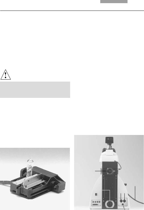
107/2 Lamp Housing
This lamp housing is used with a 12V 100W halogen lamp, which is already mounted.
In case the lamp has to be removed:
•Remove the fastener screw on the housing (Fig. 15).
•Remove the housing by pulling it upwards.
•Remove the lamp.
•Insert the new 12V 100W lamp (16.1) with the dust cover straight into the socket until it stops. Be sure that the lamp is inserted straight.
•Remove the lamp’s dust cover.
Caution!
Do not remove the lamp’s dust cover until you have installed the lamp. Avoid fingerprints on the lamp.
•Replace the housing and fasten it in place using the fastening screw.
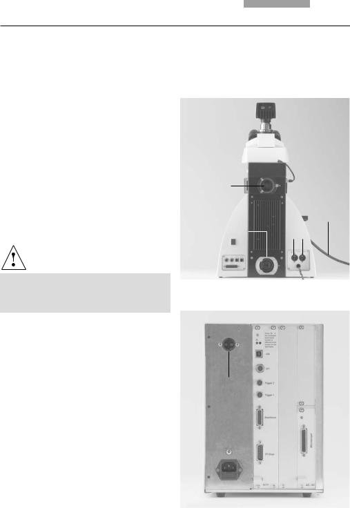
•Place the lamp housing in the transmitted light lamp housing receptacle (17.2) and fasten it with the clamping screw on the side.
•Connect the lamp housing to the power supply for transmitted light (symbol:  ) (17.3).
•Now connect the lamp power cable of the microscope (17.5) to the Leica CTR5500 or CTR6000 Electronics Box (18.1).
Fig. 17 Rear side of stand
1Incident light lamp housing receptacle
2Transmitted light lamp housing receptacle
312 V 100 W connection for transmitted light (symbol:  )
)
412 V 100 W connection for incident light (symbol:  )
)
5Lamp power cable
1
5
2 |
|
3 |
4 |
|
Fig. 18 Rear side of Leica CTR6000
1 Connection for lamp power cable from the stand
1
25
6. Assembly
6.6 Light Sources for the Incident Light Axis
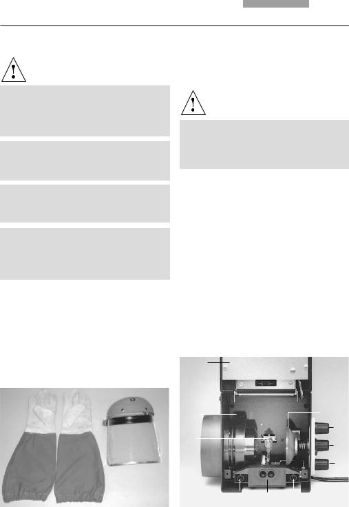
Caution!
Light sources pose a potential irradiation risk (glare, UV-radiation, IR-radiation). Therefore, lamps have to be operated in closed housings.
During assembly, always unplug the power supply unit of the 106 z lamp housing from its socket.
During assembly work on xenon burners, always wear the supplied protective gloves and face protection (Fig. 19) (risk of explosion).
Never touch the glass parts of the burner with bare hands.
Never look directly into the beam path (blinding hazard).
Fig. 19
Protective gloves and mask
6.6.1 106 z lamp housing
This lamp housing is used with a 12V 100W halogen lamp or various gas discharge lamps.
Caution!
Make sure to follow the instructions and safety notes of the lamp supplier.
Before changing lamps allow at least 30 mins for cooling down!
Fig. 20 106 z lamp housing (on the side, open)
1Cover raised
2Collector
312 V 100 W lamp or
gas discharge lamp in mount
4Reflector (mirror)
5, 6, 7 Adjusting screw for x-y reflector
8Fastening screw for lamp mount
9Socket for contact plug
1
2 |
4 |
5
3
6
7
8 |
9 |
8 |
26
6. Assembly
Inserting the 12V 100W halogen lamp into the 106 z lamp housing
•Unscrew the fastening screws of the cover and lift up the cover (20.1).
•Unscrew the fastening screws of the lamp mount (20.8) and pull out the mount (Fig. 21).
•Insert the lamp with the dust cover straight into the socket until it stops.
Caution!
Do not remove the lamp’s dust cover until you have installed the lamp. Avoid fingerprints on the lamp.
• Remove the dust cover.
Fig. 21 Lamp mount with 12 V 100 W halogen lamp
•Reinsert the lamp mount and retighten the fastening screw (20.8).
•Close the lamp housing and retighten the fastening screws.
•Place the lamp housing in the incident light lamp housing receptacle (22.1) and fasten it with the clamping screw on the side.
•Connect the lamp housing to the power supply for incident light (symbol  ) (22.4).
•Now connect the lamp power cable of the microscope (22.5) to the Leica CTR5500 or CTR6000 electronics box (18.1, p. 25)
Fig. 22 Rear side of stand
1Incident light lamp housing receptacle
2Transmitted light lamp housing receptacle
312 V 100 W connection for transmitted light (symbol:  )
)
412 V 100 W connection for incident light (symbol:  )
)
5Lamp power cable
1
5
2 |
|
3 |
4 |
|
27

6. Assembly
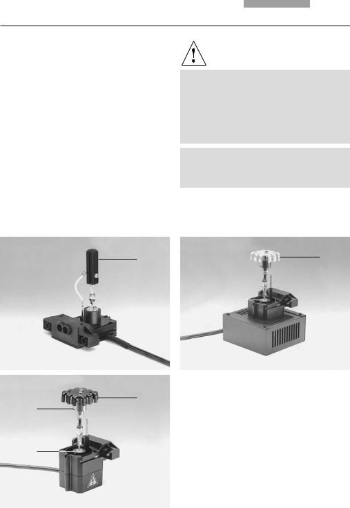
Inserting the gas discharge lamps (Hg and Xe) into the 106z lamp housing
Hg and Xe lamps are powered by separate supply units.
Read the separate instruction manual provided with these supply units.
The following gas discharge lamps may be used and require different supply units and lamp mounts (Fig. 23):
Type |
Typical bulb life* |
|
|
|
|
50 |
W high-pressure mercury burner (alternating current) |
100 hrs. |
100 W high-pressure mercury burner (direct current) |
200 hrs. |
|
100 W high-pressure mercury burner (direct current, type 103 W/2) |
300 hrs. |
|
75 |
W High-pressure xenon burner (direct current) |
400 hrs. |
* Please regard the data sheets of the burners.
28
6. Assembly
•To open the 106 z lamp housing, unscrew the fastening screws on the cover.
•Remove the transport anchorage (red plastic rod in place of the burner) in the lamp mount. To do so, remove the lower clamp (23.1). Pull up the cooling element (23.3) and turn it to the side. Detach the lower clamp system (23.2) and remove the transport anchorage.
•Install the burner in reverse order.
Caution!
Hg 50 burner:
After installation, the labeling must be upright. If a glass melt nipple is present (23a.4), position it by turning the burner so that the nipple does not come in the way of the beam path later, but instead is positioned sideways.
Xe 75 burner:
Remove the burner’s dust cover (23b.5) after you have installed the burner.
Fig. 23 a-c Lamp mounts for gas discharge lamps
1 Upper clamping system, 2 Lower clamping system, 3 Cooling element
4 Nipple of the mercury 50 burner, 5 Dust cover of the mercury 75 burner
1 |
|
|
|
|
|
|
1 |
|
|
|
|
5 |
|
|
|
|
|
|
|
|
|
|
|||
|
|
|
|
|
|
|
|
|
|
|
||
|
|
|
|
|
|
|
|
|
|
|
||
4 |
|
|
|
|
|
|
|
|
||||
|
|
|
|
|
|
2 |
|
|
|
|
|
|
|
|
|
|
|
|
|
|
|
|
|
||
Hg 50 |
|
a |
Xe 75 |
|
|
|
|
|
b |
|||
|
|
|
|
3 |
|
3 |
||||||
|
|
|
|
|
2 |
|
|
|
|
|
|
|
|
|
|
|
|
|
|
|
|
|
|
|
|
Hg 100 c
3
1
2
29

6. Assembly
•Insert the lamp mount, with the burner installed, into the lamp housing and tighten it with the screws (24.8).
•Put the lid down again. Plug in the contact plug as far as it goes and retighten the screws.
•Place the lamp housing in the incident light lamp housing receptacle (25.1) and fasten it with the clamping screw on the side.
•Connect the lamp housing to the power supply (26.1).
Fig. 25 Rear side of stand
1Incident light lamp housing receptacle
2Transmitted light lamp housing receptacle
312 V 100 W connection for transmitted light (symbol:  )
)
412 V 100 W connection for incident light (symbol:  )
)
5Lamp power cable
Fig. 24 106 z lamp housing (on the side, open)
1Cover raised
2Collector
312 V 100 W lamp or
gas discharge lamp in mount
4Reflector (mirror)
5, 6, 7 Adjusting screw for x-y reflector
8Fastening screw for lamp mount
9Socket for contact plug
1
2 |
4 |
5
3
6
7
8 |
9 |
8 |
Fig. 26 Rear side of the ebq 100 supply unit 1 Lamp connection
1
1
5
2 |
|
3 |
4 |
|
30
 Loading...