

Leica DM1000
Leica DM1000 LED
Operating Manual · Bedienungsanleitung · Mode d’emploi

Published June 2010 by/
Herausgegeben Juni 2010 von/
Publiée en june 2010 par :
Leica Microsystems CMS GmbH
Ernst-Leitz-Strasse 17-37
D-35578 Wetzlar (Germany)
Responsible for contents/
Verantwortlich für den Inhalt/
Responsable du contenu rédactionnel :
Peter Schmitt, Manuela Jacobsen
(Clinical Imaging, Product Management)
Holger Grasse
(Safety Offi cer according to MPG §30/
Sicherheitsbeauftragter nach MPG §30/
Responsable de la sécurité conformément à la loi
relative aux dispositifs médicaux, §30)
In case of questions, please contact the hotline/
Bei Fragen wenden Sie sich bitte an die Hotline/
Pour toute question, contacter notre service
d’assistance téléphonique :
Phone/Tel./Tél. +49 (0) 64 41-29 4253
Fax +49 (0) 64 41-29 2255
E-Mail/e-mail/courriel MQM-Hotline@leica-
microsystems.com

Leica DM1000
Leica DM1000 LED
Operating Manual

Copyrights
Copyrights
All rights to this documentation are held by
Leica Microsystems CMS GmbH. Reproduction
of text or illustrations (in whole or in part) by
print, photocopy, microfilm or other method (including electronic systems) is not allowed without express written permission from Leica
Microsystems CMS GmbH.
The instructions contained in the following
documentation reflect state-of-the-art technology.
We have compiled the texts and illustrations as
accurately as possible. Nevertheless, no liability
of any kind may be assumed for the accuracy of
this manual’s contents. Still, we are always
grateful for comments and suggestions
regarding potential mistakes within this
documentation.
The information in this manual is subject to modification at any time and without notification.
4

Contents
Contents
1. Important Notes about this Manual ...... 6
2. Intended Purpose of the Microscope ... 7
3. Safety Notes ............................................... 8
3.1 General Safety Notes ............................... 8
3.2 Electrical Safety ........................................ 8
3.3 Disposal ....................................................... 9
4. Overview of the Instrument .................... 10
5. Unpacking the Microscope .................... 14
6. Assembling the Microscope .................. 16
6.1 Stage ............................................................ 16
6.2 Condenser ................................................... 18
6.3 Tube and Eyepieces .................................. 19
6.4 Objectives ................................................... 19
6.5 Light Source - Transmitted Light Axis ... 20
6.6 Components for
Fluorescence Applications...................... 21
6.6.1 Fluorescence Illuminator .............. 21
6.6.2 106z Lamp Housing ......................... 21
6.7 Analyzer and Polarizer* .......................... 24
6.8 Lambda Plate Compensator .................... 24
6.9 Optional Accessories ............................... 25
6.10 Insertion of the batteries ......................... 27
6.11 Connection to the Power Supply............ 27
7. Startup ......................................................... 28
7.1 Switching on the Microscope................. 28
7.2 Köhler Illumination .................................... 28
7.3 Checking Phase Contrast Rings ............. 29
7.4 Adjusting the Light Sources .................... 31
8.3 Focusing ...................................................... 36
8.4 Tubes....................................................... 37
8.5 Eyepieces.................................................... 38
8.6 Objectives ................................................... 39
8.7 Light Sources ............................................. 40
8.8 Aperture Diaphragm ................................. 40
8.9 Field Diaphragm ......................................... 41
9. Contrast Methods ...................................... 42
9.1 Transmitted Light ....................................... 42
9.1.1 Brightfield......................................... 43
9.1.2 Phase Contrast................................ 44
9.1.3 Darkfield ........................................... 44
9.1.4 Oblique Illumination ....................... 45
9.1.5 Polarization ...................................... 45
9.2 Fluorescence.............................................. 46
10. Measurements with the Microscope ... 47
10.1 Linear Measurements .............................. 47
10.2 Thickness Measurements ....................... 48
10.3 Differentiation of Gout / Pseudo Gout ... 49
11. Trouble Shooting ....................................... 51
12. Care of the Microscope ........................... 54
12.1 Dust Cover .................................................. 54
12.2 Cleaning....................................................... 54
12.3 Handling Acids and Bases ...................... 55
12.4 Changing Fuses.......................................... 55
13. Essential Wear and Spare Parts ............ 56
14. Retrofitting Components .......................... 57
14.1 Equipping the Condenser Disk................ 57
8. Operation .................................................... 35
8.1 Switching on............................................... 35
8.2 Stages and Object Displacement........... 35
15. Index ............................................................ 59
16. EC Declaration of Conformity ................. 60
5
1. Important Notes about this Manual
1. Important Notes about this Manual
Caution!
This operating manual is an essential component of the microscope, and must be read
carefully before the microscope is
assembled, put into operation or used.
Text symbols, pictograms and their meanings:
(1.2)
→
p. 20
!
This operating manual contains important instructions and information for the operational
safety and maintenance of the microscope and
accessories. Therefore, it must be kept and
taken care of.
Numbers in parentheses, such as "(1.2)", correspond to illustrations (in the example, figure 1,
item 2).
Numbers with pointer arrows (for example
→ p. 20), point to a certain page of this manual.
Caution!
Special safety instructions within this
manual are indicated with the triangle
symbol shown here, and have a gray
background.
Caution! The microscope and accessories can
be damaged when operated incorrectly.
Notes on the disposal of the device,
accessories and consumable materials.
Explanatory note
*
6
Item not contained in all configurations
2. Intended Purpose of the Microscope
2. Intended Purpose of the Microscope
The Leica DM1000/DM1000 LED microscope, to
which this user manual belongs, is designed for
biological routine and research applications.
This includes the examination of samples taken
from the human body with a view to provide
information on physiological or pathological
states or congenital abnormalities, or to
determine the safety and compatibility with potential recipients, or to monitor therapeutic
measures.
The above-named microscope complies with
the Council Directive 98/79/EEC concerning in
vitro diagnostics. (It also conforms to the
Council Directives 2006/95/EC concerning
electrical apparatus and 2004/108/EC
concerning electromagnetic compatibility for
use in an industrial environment.)
The manufacturer assumes no liability for
damage caused by, or any risks arising from
using the microscope for other purposes
than those for which they are intended or
not using them within the specifications of
Leica Microsystems CMS GmbH.
In such cases the conformity declaration
shall cease to be valid.
These (IVD) devices are not intended for use
in the patient environment defined by DIN
VDE 0100-710. Neither are they intended for
combining with medical devices according
to EN 60601-1. If a microscope is electrically
connected to a medical device according to
EN 60601-1, the requirements defined in
EN 60601-1-1 shall apply.
Not suitable for examining potentially
infectious specimens.
Caution!
Caution!
7
3. Safety Notes
3. Safety Notes
3.1 General Safety Notes
This safety class 1 (DM1000) or class 2
(DM1000 LED) device is constructed and tested
in accordance with
EN 61010-2-101:2002 (DM1000/DM1000 LED),
EN 61010-1:2001 (DM1000/DM1000 LED),
IEC 61010-1:2001 (DM1000/DM1000 LED),
IEC 60825-1:2007 (DM1000 LED)
EN 60825-1 + A1 + A2:2003 (DM1000 LED),
LED Class I (DM1000 LED)
safety regulations for electrical measuring, control, and laboratory devices.
Caution!
In order to maintain this condition and to ensure safe operation, the user must follow the
instructions and warnings contained in this
operating manual.
Caution!
The devices and accessories described in
this operating manual have been tested for
safety and potential hazards.
The responsible Leica affiliate or the main
plant in Wetzlar, Germany must be consulted
whenever the device is altered, modified or
used in conjunction with non-Leica components that are outside of the scope of this
manual.
3.2 Electrical Safety
General Specifications
Microscope
For indoor use only.
Supply voltage:
Power input:
Fuses:
Ambient temperature:
Relative humidity:
Over voltage category:
Pollution degree:
Specifications of the external power supply
ELPAC POWER SYSTEMS power supply,
Model: FW1812
Input: 100-240 V AC
0,5 A
47-63 Hz
Output: 12 V DC
1,5 A max.
18 W max.
Caution!
90-250 V AC, 50-60 Hz
(DM1000)
12 V DC, 1.5 A
(DM1000 LED)
40 W (DM1000)
18 W (DM1000 LED)
F 3.15 A 250 V
(DM1000)
Integrated in external
power supply unit,
not replaceable
(DM1000 LED)
15-35°C
max. 80% to 30°C
II
2
Unauthorized alterations to the device or
noncompliant use shall void all rights to any
warranty claims and product liability!
8
Use the original power supply only. Other
power supplies must not be used.

3. Safety Notes
If the original power supply fails or is
damaged, it must be replaced. Repair is not
permitted.
Original power supplies are available from
your Leica branch office or Leica dealer.
Caution!
The power plug may only be plugged into an
outlet equipped with a grounding contact.
Do not interfere with the grounding function
by using an extension cord without a ground
wire. Any interruption of the ground wire inside or outside of the device, or release of
the ground wire connection, can cause the
device to become hazardous. Intentional
ground interruption is not permitted!
Caution!
DM1000 only: Never use any fuses as
replacements other than those of the types
and the current ratings listed here. Using
patched fuses or bridging the fuse holder is
not permitted. The use of incorrect fuses
may result in a fire hazard.
Caution!
Protect the microscope from excessive temperature fluctuations. Such fluctuations can
lead to the accumulation of condensation,
which can damage the electrical and optical
components.
Ambient temperature: 15-35°C.
Caution!
DM1000 only: Before exchanging the fuses
or lamps, be absolutely certain to switch off
the main power switch and remove the power cable.
3.3 Disposal
To dispose of the product at the end of its service life, please contact Leica Service or Sales.
Please observe national laws and regulations,
such as those implementing and enforcing the
WEEE EU directive.
Note:
Caution!
The microscope's electrical accessory components are not protected against water.
Water can cause electric shock.
Like other electronic devices, the microscope and its accessory components must
not be disposed of as regular household
waste.
9

4. Overview of the Instrument
4. Overview of the Instrument
Specification
Contrast Methods
Transmitted Light Axis
Incident Light Axis
(optional)
Tube
Leica DM1000/DM1000 LED
• Transmitted light: brightfield, darkfield,
phase contrast, polarization
• Incident light: fluorescence
Leica DM1000: Integrated halogen illumination
Leica DM1000 LED: Integrated LED illumination
manual adjustment of
• Light intensity
• Aperture diaphragm
• Field diaphragm (only with Köhler kit)
Incident light fluorescence illuminator for eyepieces with
field number up to 20 with
• Interchangeable slide with mount for 3 filter systems
• Adjusting lens for lamp
• Light trap for the suppression of extraneous light
• BG38 blue filter and shutter, switchable
optionally with
• Fixed or variable viewing angle
• Up to 3 switching positions
• one or two camera ports
• Ergotube with height-adjustable eye level and camera port
Magnification Changer
(optional)
Objective Turret
X/Y Stage
10
• Manual
• Magnification steps: 1x; 1.5x; 2x
• Manual
• 5-fold for objectives with M25 thread
• With condenser holder
• Coaxial pinion, optional telescopable
• Controls mountable left or right

4. Overview of the Instrument
Specification
Condenser
Focusing
Leica DM1000/DM1000 LED
optionally with
• CL/PH 0.90/1.25 OIL condenser with color coding
• CLP/PH 0.85 condenser for polarization
• Achr.apl. A 0.9 (P) condenser with swivelable condenser head
• UCL 0.90/1.25 OIL universal condenser UCLP 0.85 for
polarization with 5-position light ring disk)
• UCL/P pol. universal condenser with interchangeable
condenser head and condenser disk with 6 positions
• Focus wheel for coarse and fine focusing
• Height adjustment
11
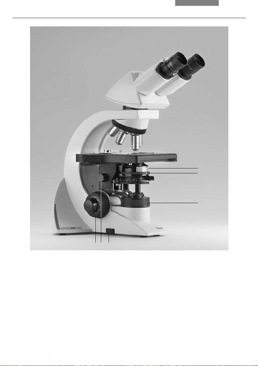
4. Overview of the Instrument
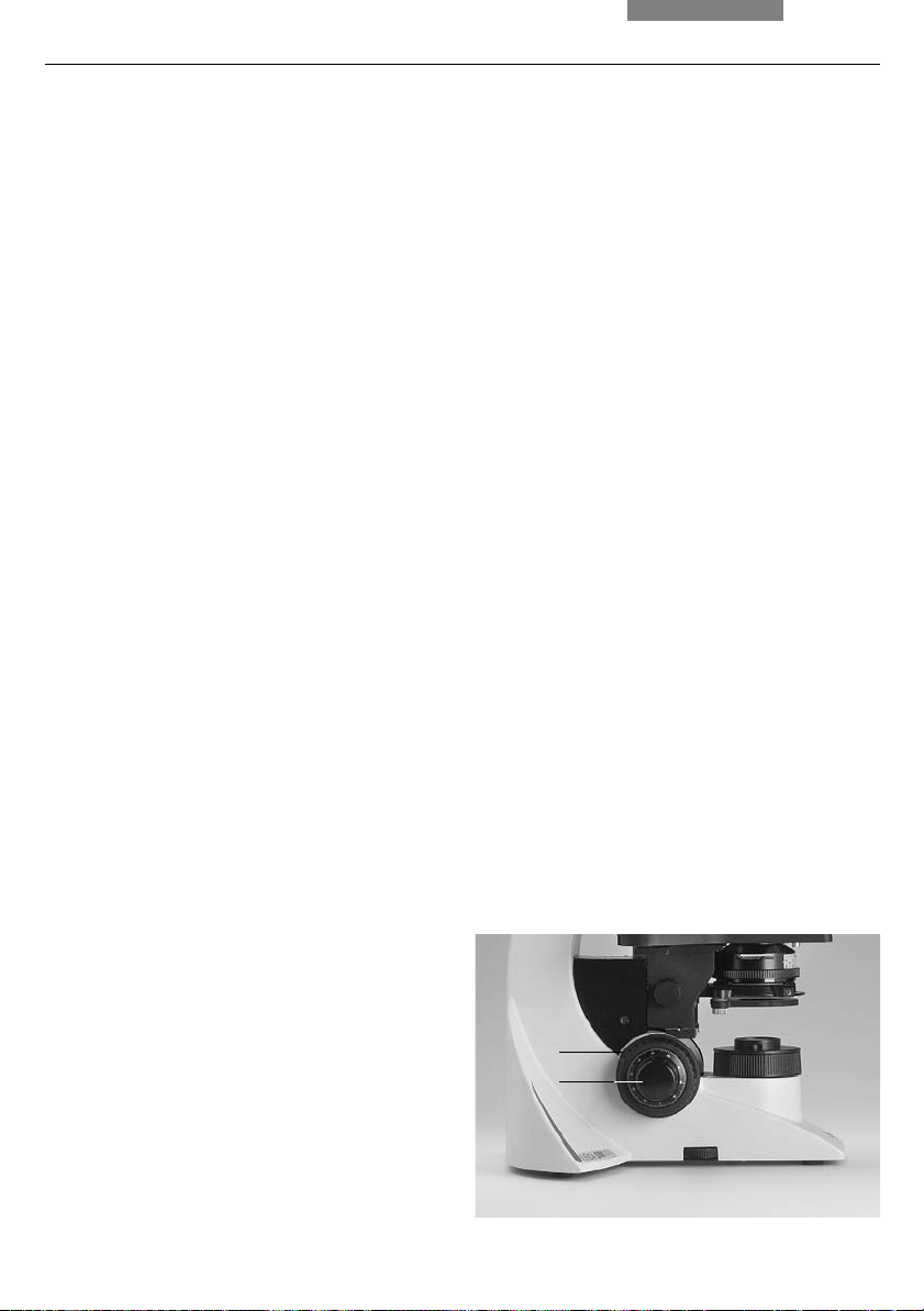
6
5
Fig. 1 Left side of the Leica DM1000 stand
1 Coarse and fine focusing
2 Condenser height adjustment
3 Brightness control
4 Field diaphragm
5 Aperture diaphragm
6 Condenser
12
4
12 3

4. Overview of the Instrument
1
2
3
4
5
Fig. 2 Right side of the Leica DM1000 stand
1 Eyepiece
2 Eyepiece tube
3 Tube
4 Objective turret with objectives
5 Specimen stage with specimen holder
6 Integrated illumination
7 On/Off switch
8 Condenser height adjustment
9 Coarse and fine focusing
10 Coaxial pinion for x/y stage movement
678910
13
5. Unpacking the Microscope
5. Unpacking the Microscope
First, carefully remove all components from the
transportation and packaging materials.
Note:
If at all possible, avoid touching the lens surfaces of the objectives. If fingerprints do appear
on the glass surfaces, remove them with a soft
leather or linen cloth. Even small traces of finger
perspiration can damage the surfaces in a short
time. See the chapter "Care of the Microscope"
p. 54, for additional instructions.
→
Caution!
Do not yet connect the microscope and peripherals to the power supply at this point!
Installation Location
Work with the microscope should be performed
in a dust-free room, which is free of vapors (oil,
chemicals etc.) and of extreme humidity. At the
workplace, large temperature fluctuations,
direct sunlight and vibrations should be avoided.
These conditions can distort measurements and
micrographic images.
Allowable ambient conditions
Temperature 15-35°C
Relative humidity maximum 80% up to 30°C
Microscopes in warm and warm-damp climatic
zones require special care in order to prevent
the build up of fungus.
See the chapter "Care of the Microscope" →
for additional instructions.
Caution!
Electrical components must be placed at least
10 cm away from the wall and away from
flammable substances.
p. 54,
14

Transport
For shipping or transporting the microscope
and its accessory components, the original
packaging should be used.
As a precaution to prevent damage from vibrations, the following components should be disassembled and packaged separately:
• Unscrew the objectives
• Remove the condenser
• Remove the coaxial pinion
• Remove the lamp housings
• Disassemble the burner of 106z lamp housing
• Remove all moving or loose parts
5. Unpacking the Microscope
15
6. Assembly
6. Assembling the Microscope
The microscope components are logically assembled in this order:
• Stage
• Condenser
• Fluorescence illuminator*
• Intermediate systems*
• Tube
• Eyepieces
• Objectives
• Lamp housings with light sources*
• Polarization equipment*
Only one commonly used screwdriver is
necessary for assembly, which is included in the
delivery package.
The tool can be stored on a magnetic retainer
on the underside of the stage at the right.
When using intermediate systems and optical
accessories, the sequence may vary.
In this case, read Chapter
"6.9 Optional Accessories" → p. 25.
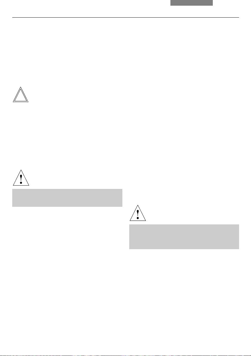
6.1 Stage
Caution:
!
Before completing the stage, make sure no objectives are installed!
Remove the srew located under the stage in the
front.
Specimen Holder
Coaxial Pinion
Note:
The coaxial pinion can be mounted on the leftor right-hand side.
• First, place the flat fine focus wheel on the
side to which you intend to mount the coaxial
pinion; the wheel is held in place magnetically
(4.1); ensure that the button snaps into place.
Attach the other focus knob on the opposite side
• Loosen the lock screw (5.1) at the front lefthand side of the stage
• Slide the stage as far back as possible
• Attach the coaxial pinion with the srew (6.1)
• Return the stage to the starting position and
retighten the lock screw; after installation of
the stage control, move object guide all the
way to the left side of the instrument; keep
turning when guide has reached the end of
travel until a click noise is heard
Fig. 3 Specimen stage with specimen holder
1 Lock screws for specimen holder
1
• Place the specimen holder on the stage and
fasten it with the two screws (3.1)
16
6. Assembly
Adjusting the Focus Stop
The focus stop is preadjusted by the factory to
prevent collision with objectives. The focus stop
should be set approx. 0.3 mm higher as the focal
plane to enable focussing of the samples of different thickness.
If a readjustment is necessary, adjust as
following:
• Lower the stage by rotating 1/2 turn of the
coarse adjustment knob
• Loosen the focus stop screw on left hand side
of microscope
• Move stage to desired focal plane (preferably
approx. 0.3 mm higher)
• Tighten focus stop screw
Stage Lock*
The stage lock is mounted in the same hole as
the stage drive (in case of ErgoStages, it can be
mounted on the opposite position in addition to
stage drive).
The mounting of stage lock is similar to
mounting of the stage drive:
• Loosen the locking screw (5.1) on the left side
underside of stage and move the stage all the
way back
• Loosen the screw for coaxial pinion (6.1),
remove the coaxial pinion, and attach the
stage lock with this screw
• Loosen the stage lock screw and pull the
stage forward to the desired position
• Retighten the locking screw (5.1) underside of
stage
• Press the pinion of the stage lock against the
rack and retighten the stage lock screw
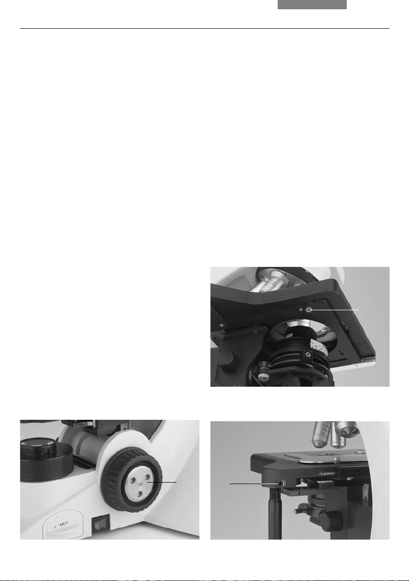
Fig. 5 Underside of stage
1 Lock screw
1
Fig. 4 Focus wheel
1 Magnetic retainer for fine focus wheel
Fig. 6 Coaxial pinion installation
1 Mounting screw for coaxial pinion
1
1
17
6. Assembly
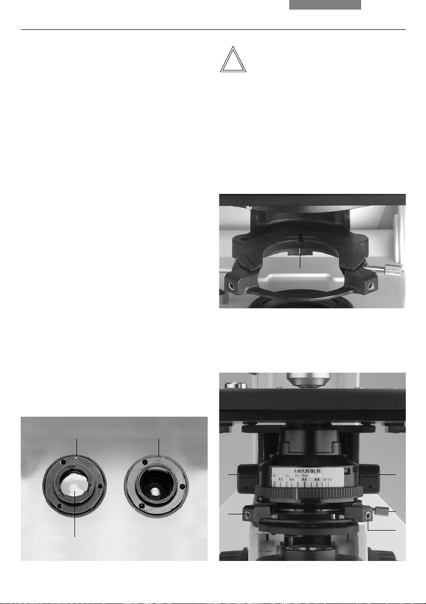
6.2 Condenser
• If present, screw the condenser head into the
condenser
• Using the condenser height adjuster (9.3), turn
the condenser holder (fig. 8) completely
downward
• Unscrew the clamping screw for the condenser (9.2) far enough so that the condenser
can be inserted from the front
• From the front, insert the condenser into the
condenser holder as far as it will go; on the
underside of the condenser, there is an orientation pin (7.1), which must be located in the
guiding notch (8.1)
• Pull the condenser's clamping screw (9.2) so
that the condenser is locked in place
Fig. 7 Underside of condenser (example CL/PH)
1 Orientation pin
2 Auxiliary condenser lens LS
Note:
The condenser must be centered before using
the microscope.
Köhler illumination p. 28.
→
Fig. 8 Condenser holder
1 Guiding notch
1
Fig. 9 Condenser holder
1 Condenser centering bolts
2 Clamping screw for condenser
3 Condenser height adjuster
18
1
1
3
1
3
2
1
2

6. Assembly
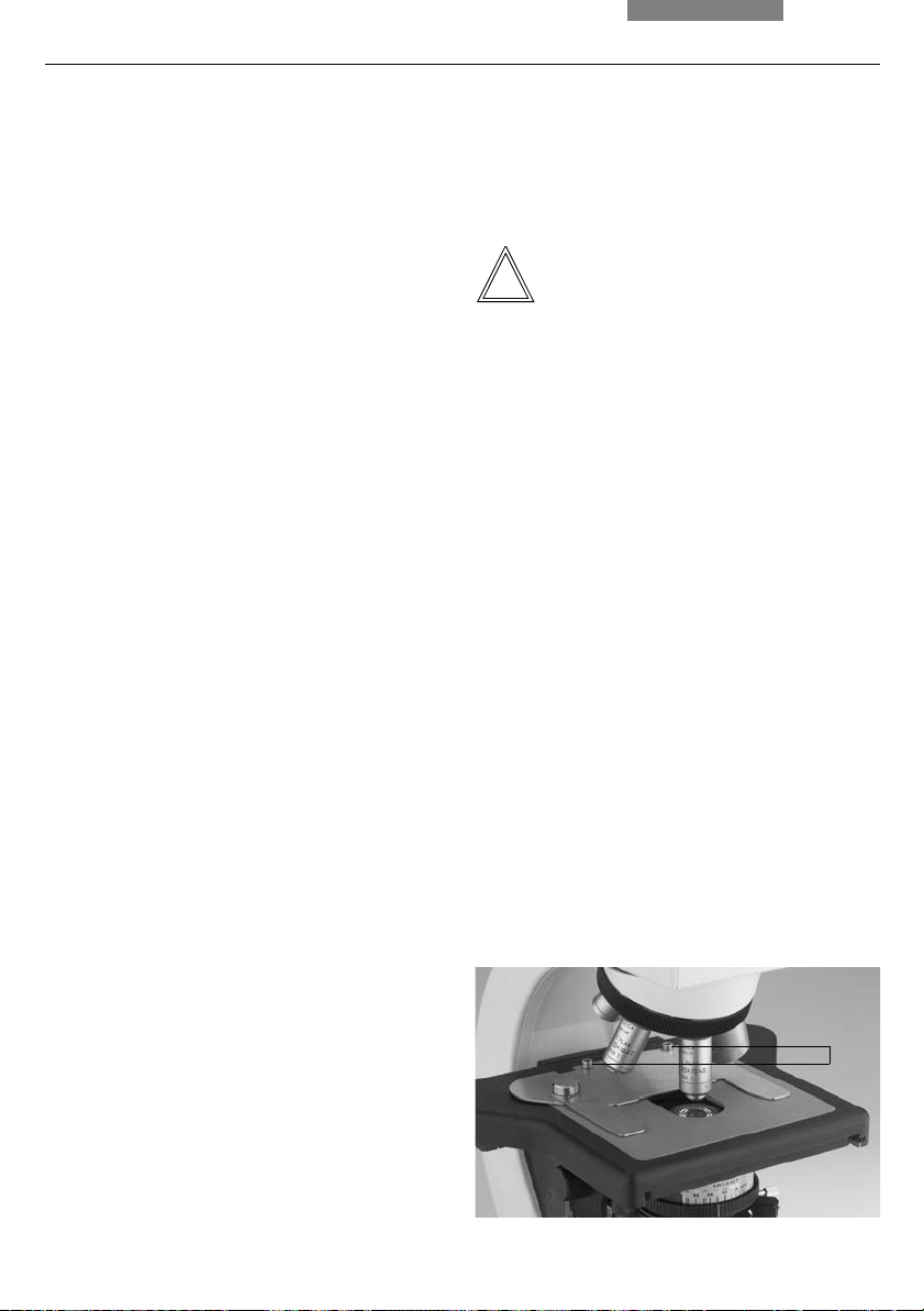
6.3 Tube and Eyepieces
Note:
For fluorescence applications, install the
fluorescence illuminator* first → p. 21.
If available, the analyzer* (10.1) must be
inserted into the stand. This requires that the
guide key engages in the guide pin (10.2).
To mount the analyzer, the analyzer mount TL*
20 mm or 60 mm can also be placed between
stand and tube.
An intermediate tube pole* with a switchable
analyzer (on/off) and Bertrand lens is also
available as an option.
The tube is mounted to the stand either directly or
with the use of intermediate modules*.
• Loosen the clamping screw (11.1) on the
stand
• Insert the tube in the circular receptacle
(dovetail ring)
• Retighten the clamping screw (11.1)
• The eyepieces are inserted into the eyepiece
tubes on the tube
6.4 Objectives
Always only use Leica objectives of tube length ¥
(infinity)! The standard thread is M25. The
objectives should be arranged so that the
magnification increases when the objective
nosepiece is rotated counter-clockwise.
!
Attention:
Lower the specimen stage as far as possible
before assembling the objectives. Close vacant
threads in the nosepiece with dust protection
caps!
Fig. 10 Analyzer mounting
1 Analyzer
2 Orientation pin and guiding notch
3 Clamping screw
Fig. 11 Fastening the tube
1 Clamping screw
1
19

6. Assembly
6.5 Light Source for the Transmitted Light Axis
Caution!
Note:
The Leica DM1000 LED is equipped with
integrated LED illumination. The service life of
the LED is about 100.000 hours. If, despite this, it
should be necessary to change the LED, this
task must be carried out by Technical Service
only.
The following instructions in this chapter refer to
the Leica DM1000 with tungsten halogen lamp.
Caution!
Be sure that the microscope and lamp
housing are disconnected from the power
supply. Unplug the power plug and the power supply during assembly.
Light sources pose a potential irradiation
risk (glare, UV-radiation, IR-radiation).
Therefore, lamps have to be operated in
closed housings.
Replacing the Lamp of the Integrated
Illumination
The transmitted light illumination with a lowvoltage tungsten halogen lamp (fig. 12) is
integrated in the base of the microscope and is
accessible from the right-hand side.
• Remove the insert (12.2)
Caution!
The lamp may still be hot!
• Remove the lamp
Caution!
Fig. 12 Transmitted-light illumination
in Leica DM1000 microscope base
1 Tungsten halogen lamp
2 Insert
12
20
Do not remove the new lamp's dust cover
until you have installed the lamp. Avoid
fingerprints on the lamp.
• Insert the new lamp with the dust cover
straight into the socket until it stops; be sure
that the lamp is inserted straight
• Remove the lamp's dust cover
• Replace the insert (12.2)
6.6 Components for Fluorescence Applications*
6.6.1 Fluorescence illuminator*
6. Assembly
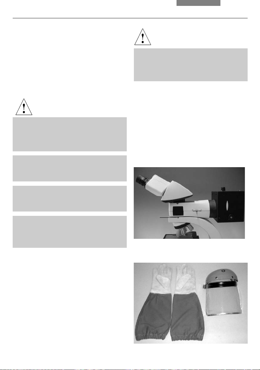
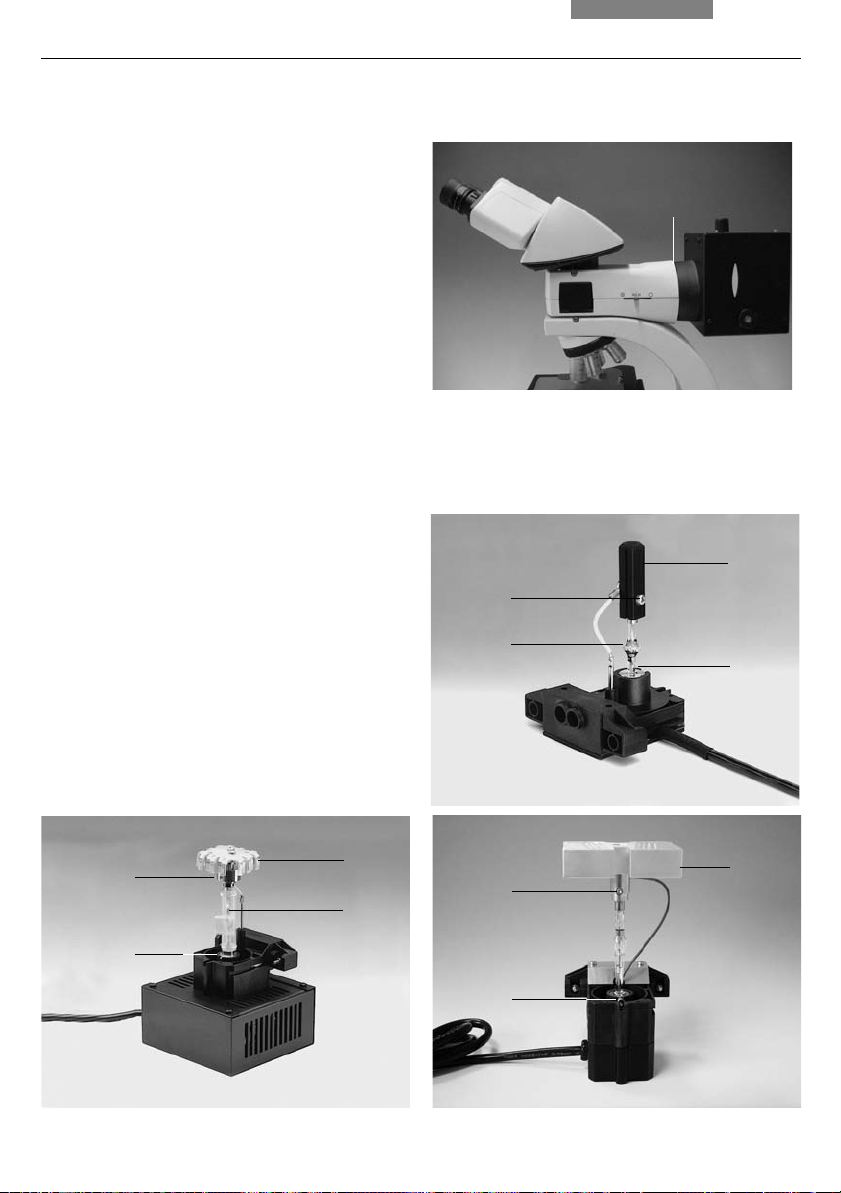
Caution!
The fluorescence illuminator is mounted before
the tube. It is fastened in place with the side
clamping screw (13.1).
6.6.2 106z Lamp Housing*
Caution!
Light sources pose a potential irradiation
risk (glare, UV-radiation, IR-radiation).
Therefore, lamps have to be operated in
closed housings.
During assembly, always unplug the power
supply unit of the 106z lamp housing from its
socket.
During assembly work on xenon burners, always wear the supplied protective gloves
and face protection (fig. 14) (risk of explosion).
Never touch the glass parts of the burner
with bare hands.
Never look directly into the beam path
(blinding hazard).
Make sure to follow the instructions and
safety notes of the lamp supplier.
Before changing lamps allow at least 30 mins
for cooling down!
Inserting the Gas Discharge Lamps* (Hg and
Xe) into the 106z Lamp Housing
Hg and Xe lamps are powered by separate
supply units.
Read the separate instruction manual provided
with these supply units.
Fig. 13 Assembly of fluorescence illuminator
1 Clamping screw
1
Fig. 14
Protective gloves and mask
The lamp housing 106z is used with various gas
discharge lamps.
21

6. Assembly
The following gas discharge lamps may be used
and require different supply units and lamp
mounts (fig. 16):
Type Typical Bulb Life
50 W high-pressure mercury burner (alternating current) 100 hours
100 W high-pressure mercury burner (direct current) 200 hours
100 W high-pressure mercury burner, type 103 W/2 (direct current) 300 hours
75 W high-pressure xenon burner (direct current) 400 hours
+) Please regard the data sheets for the burners.
• To open the 106z lamp housing, unscrew the
fastening screws (15.8) on the cover
• Remove the transport anchorage (red plastic
rod in place of the burner) in the lamp mount;
to do so, remove the lower clamp (16.1); pull
up the cooling element (16.3) and turn it to the
side; detach the lower clamp system (16.2)
and remove the transport anchorage
• Install the burner in reverse order
Caution!
Fig. 15 106z lamp housing (on the side, open)
1 Cover (raised)
2 Collector
3 Gas discharge lamp in mount
4 Reflector (mirror)
5, 6, 7 Adjusting screw for x-y reflector
8 Fastening screw for lamp mount
9 Socket for contact plug
+)
Hg 50 Burner:
After installation, the labeling must be
upright.
If a glass melt nipple is present (16a.4), position
it by turning the burner so that the nipple does
not come in the way of the beam path later, but
instead is positioned
sideways.
Xe 75 Burner:
Remove the burner's dust cover (16b.5) after
you have installed the burner.
22
1
2
4
5
3
6
7
898
6. Assembly
• Insert the lamp mount, with the burner installed, into the lamp housing and tighten it
with the screws (15.8)
• Close the lamp housing and retighten the
screws
• Place the lamp housing in the incident light
lamp housing receptacle (17.1) and fasten it
with the clamping screw on the side
• Connect the lamp housing to the external
power supply
Fig. 16 a-c Lamp mounts for gas discharge lamps
1 Upper clamping system
2 Lower clamping system
3 Cooling element
4 Nipple of the mercury 50 burner,
5 Dust cover of the mercury 75 burner
Fig. 17 Mounting the 106z lamp housing
1 Lamp housing receptacle
1
Hg 50
1
4
a
3
2
Xe 75
b
Hg 100
3
1
1
c
3
5
2
2
23

6. Assembly
6.7 Analyzer and Polarizer*
Analyzer
If the analyzer was inserted into the tube mount
before the tube assembly: (→ p. 19), no additional assembly step is required.
If an intermediate tube pole* or analyzer mount
TL* is used:
• Remove the plug cap on the left side
• Insert the analyzer into the receptacle until it
latches in place
Polarizer
• Raise the condenser to its upper stop position
• Remove the DLF filter magazine from the base
if present
• Press the polarizer holder in place (Fig. 18)
• Push the polarizer with the labeled side
upward into the lower opening
Alternative:
• Attach the polarizer holder to the underside of
the condenser holder with the left clamp
screw (19.1); remove the flip-out blue filter if
required
• Push the polarizer with the labeled side
upward into the lower opening
6.8 Lambda Plate Compensator*
• Raise the condenser to its upper stop position
• Remove the DLF filter magazine from the base
if present
• Attach the lambda plate compensator to the
base
Fig. 18 Filter holder*
with two positions
24
Fig. 19 Assembly of polarizer holder*
1 Clamping screw
1

6. Assembly
6.9 Optional Accessories
Camera*
A camera can be connected via an adapter.
• Attach the adapter to the top port of the tube
and fasten it tightly with the side clamping
screw
• Screw on the camera
Note:
The size of the camera chip and the mounting
system (B-mount, C-mount, etc.) must be
considered when choosing an adapter (see
table).
Calculation of the magnification on the monitor
The magnification M
on the monitor can be
TV
calculated with the following formula or
measured with a stage micrometer and a cm
scale:
= Objective magnification x
M
TV
factor of magnification changer* x
TV adapter magnification* x
monitor diameter
chip diameter of camera
Recorded picture diagonal in mm for
1 inch 2/3 inch 1/2 inch 1/3 inch
camera camera camera camera
Without Zoom Magnification, only for 1-Chip-Cameras:
C-mount adapter 1 x HC 16 11 8 6
C-mount adapter 0.70 x HC - 15.7 11.4 7.8
C-mount adapter 0.55 x HC - - 14.5 10.9
C-mount adapter 0.35 x HC - - - 17.1
With Zoom Magnification (Vario TV Adapter) for 1-3 Chip-Cameras:
C-mount, 0.32-1.6 x HC - - 19
+)
-5 18-3.8
B-mount (ENG), 0.5-2.4 x HC (1/2-inch) - - 16-3.3 -
+)
from zoom factor 0.42 x only!
Without Zoom Magnification, for 1-3 Chip-Cameras:
C-mount adapter 1 x - - 16 12
B-mount adapter 1 x - - 16 12
B-mount adapter 1.25 x - 17.5 - F-mount adapter 1 x - - 16 12
F-mount adapter 1.25 x - 17.5 - Plus (essential requirement): TV optics 0.5 x HC
25

6. Assembly
Ergomodule*
For raising the eye level of the tube opening, the
30 mm or 60 mm ergomodule may be used.
It is fastened in place with the side clamping
screw.
Installation of the tube on the 60 mm ergomodule: The tube has to be rotated 90° degree
(eyetubes going to the right) and rotated back
into the viewing position and tightened with the
screw.
Ergolift*
A base for the stand featuring adjuster wheels
for the base’s height and angle is available to
ensure an optimal working position.
Magnification Changer*
Optionally, a magnification changer (fig. 20) can
be used, which is manually operated. On the
knurled ring, the following magnification factors
can be set:
Viewing Attachments*
Viewing attachments featuring illuminated
pointers are available for groups of 2, 3, 4, 5 and
10 viewers respectively (other configurations on
request).
The support (21.3) must be aligned precisely.
The fade-in arrow can be moved in x and y
direction.
Fig. 21 Viewing attachment
1 Movement of light pointer in x and y direction
2 Brightness control
3 Adjustment of arm support
The external power supply (illuminated arrow) is not
illustrated.
1
2
3
1x; 1.5x; 2x
Fig. 20 Magnification
changer
26
Tracing Device*
The tracing device L3/20 (fig. 22) allows an
optical overlay of large objects (next to the
microscope) on the microscope image. This
makes it easy to draw specimens by tracing
their outlines or superimposing scales.
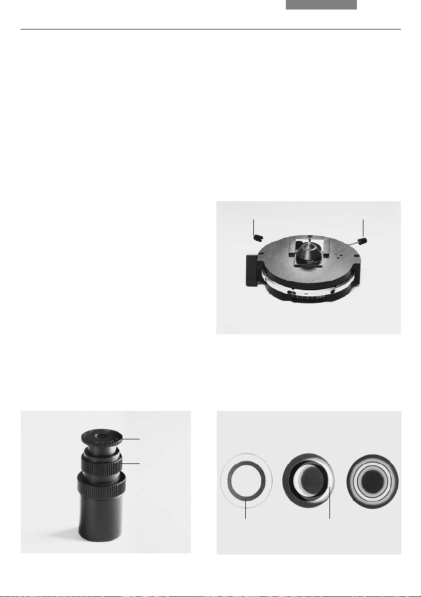
Fig. 22 Tracing device
1 Shutter
1
6. Assembly
6.10 Inserting the batteries (DM1000 LED only)*
The microscope can be powered by batteries if
you prefer. The batteries are automatically
charged when the microscope is connected to
the mains supply.
The microscope can be used for about 6-8 hours
in battery-operated mode.
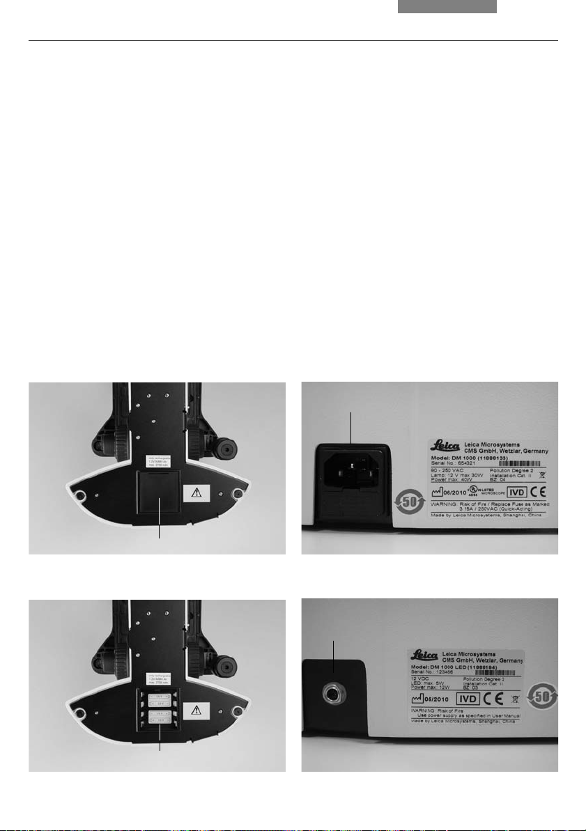
• The battery compartment is accessed from
underneath the stand (23a.1); remove the lid
of the compartment
• Insert the batteries (order no. p. 56) as shown
on the bottom of the compartment (fig. 23b)
and close the lid
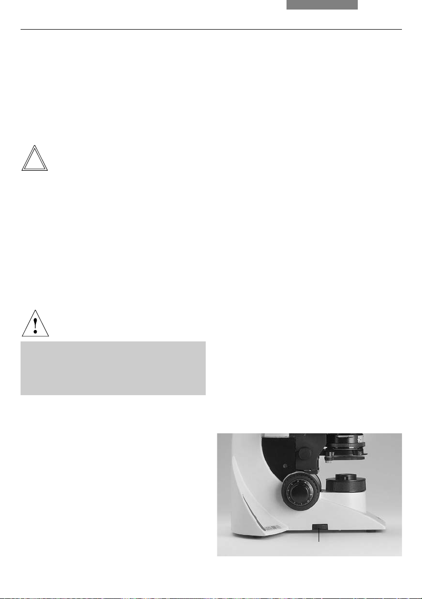
Fig. 23a Bottom of stand (DM1000 LED)
1 Lid of the battery compartment
6.11 Connection to the Power Supply
• After completing the assembly work, connect
the stand to the power supply using the power
cable supplied (fig. 23c)
• When using the lamp housing or the
external power supply unit, connect them to
the power supply, too
Fig. 23c Back of the stand (DM1000)/Type label
1 Power supply connection
1
1
Fig. 23b Bottom of stand (DM1000 LED)
1 Battery compartment open
1
Fig. 23d Back of the stand (DM1000 LED)/Type label
1 External power supply connection
1
27

7. Start-up
7. Start-up
7.1 Switching on the Microscope
• Switch on the microscope with the on/off
switch (24.1)
Caution!
After turning on the gas discharge lamp*,
the burner must be immediately adjusted.
Therefore, do not turn on the power supply*
unit yet. First, work in transmitted light in order to familiarize yourself with the microscope’s controls.
Fig. 24
1 On/Off switch
2 Focus wheel
3 Stage positioning
7.2 Köhler Illumination*
The condenser is also pre-adjusted in the
factory.
However, it may be necessary to re-adjust the
condenser in some cases. Therefore, check the
condenser centering.
The following procedure is provided for the
transmitted light brightfield illumination.
• If present click the condenser disk* into the
BF position
• If present pull the light ring slide* out of the
condenser
• Select an objective with moderate
magnification (10x-20x);
for condensers with movable condenser
heads:
Swing in the condenser top
(The condenser top is swung out for objective
magnifications < 10x.)
28
• Insert the specimen into the stage’s specimen
holder
• Focus on the specimen using the focus wheel
(24.2)
• Set the light intensity using the brightness
control (25.2)
• Close the field diaphragm (25.3) until the edge
of the diaphragm appears in the specimen
plane (26a)
21 3

7. Start-up
• Using the condenser height adjuster (25.1),
adjust the condenser until the edge of the
field diaphragm appears in sharp relief (26b)
• If the image does not appear in the middle of
the field of view (26c), the condenser must be
moved into the middle of the field of view with
the help of the two centering bolts (25.4); the
tool required for this purpose is magnetically
attached to the underside of the stage
• Open the field diaphragm just enough for it to
disappear from the field of view (26d)
Note:
The condenser height adjustment depends on
the thickness of the specimen. It may be
adjusted for different specimens.
Fig. 25
1 Condenser height adjuster
2 Brightness control
3 Field diaphragm
4 Condenser centering
7.3 Checking Phase Contrast Rings
If your microscope is equipped for the use of
phase contrast, the light rings that fit the objectives are built into the condenser disk*.
The light rings are already centered in the
factory. However, the centering should be
rechecked.
Note:
A light ring slide which is inserted into the side
of the condenser is used for condensers without
condenser disks. Centering is not required in
this case.
Note:
When swivelling in a suitable objective for
phase contrast, the corresponding light ring
must be chosen.
The objective engraving (e.g. PH 1) indicates the
corresponding light ring (e.g. 1).
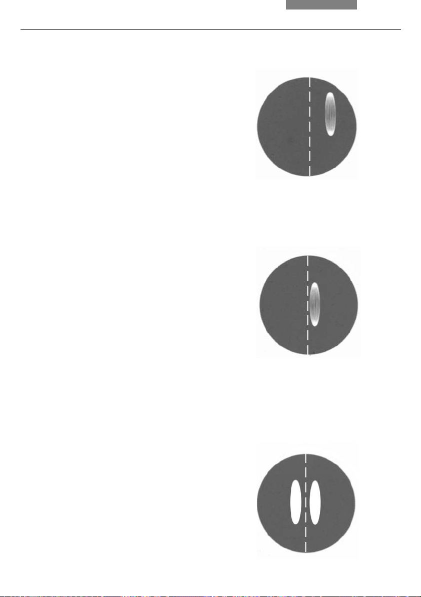
Fig. 26 Köhler illumination
a Field diaphragm not focused, not centered
b Field diaphragm focused, but not centered
c Field diaphragm focused and centered,
diameter is too small, however
d Field diameter (light) = Field diameter (view)
(Köhler illumination)
12 3
4
a
b
cd
29
7. Start-up
• In the place of an eyepiece, insert the focusing telescope (fig. 27) into the observation
tube
• Swivel in the phase contrast objective with
the lowest magnification
• Focus on the specimen with the focus wheel
• Focus the ring structure (29.a) by slightly loosening the clamping ring (27.2) and moving the
eye lens (27.1)
• Retighten the clamping ring
• Select the corresponding ring diaphragm
(light ring) in the condenser.
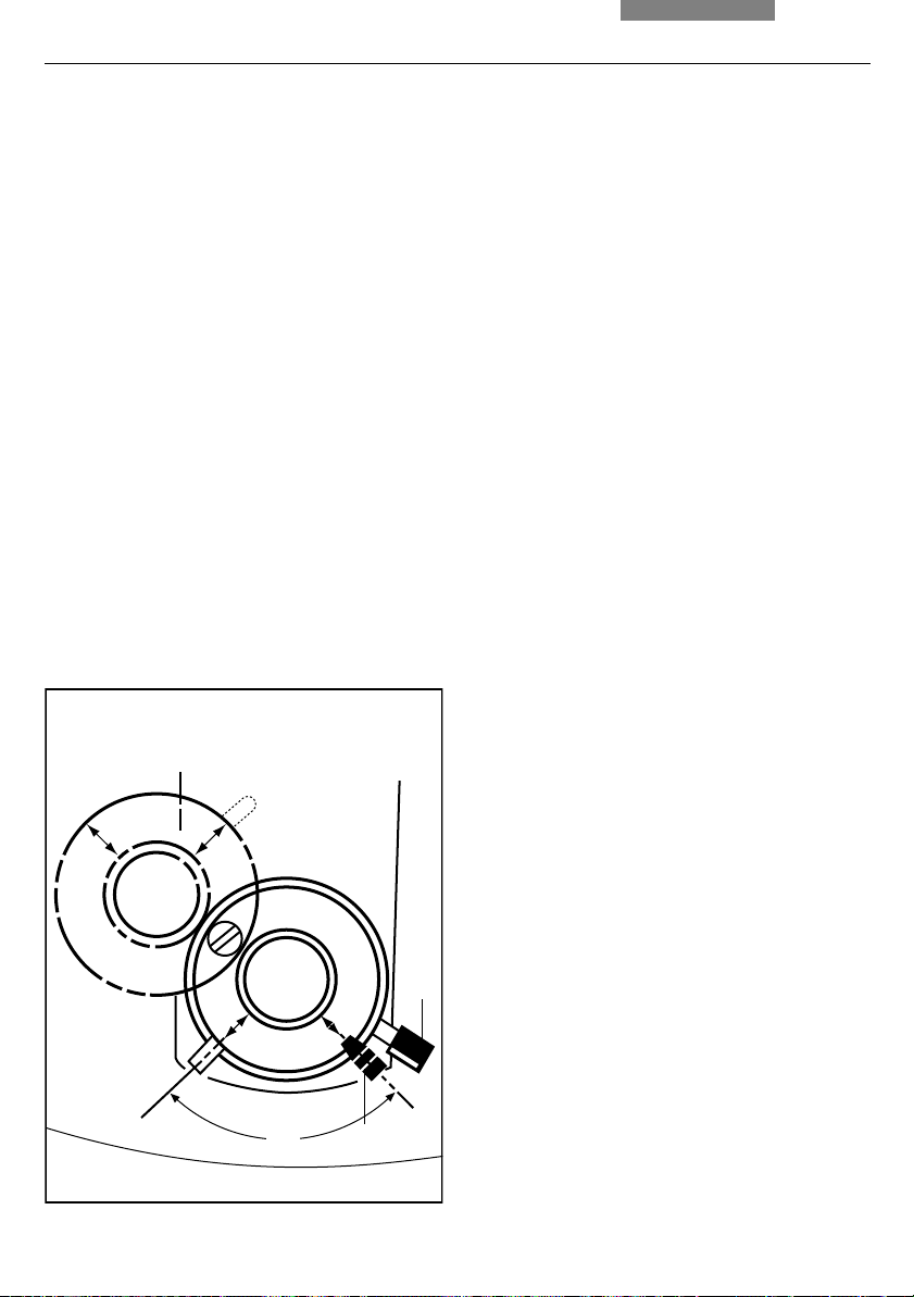
• If the light ring and the phase ring are not
shown as arranged in fig. 29.c, the light ring
must be centered
• Insert the centering screws into the openings
provided at the rear of the condenser (28.1)
• Turn the centering screws until the dark ring
(phase ring in the objective) is congruent with
the slightly narrower bright ring (light ring in
condenser) (29 c)
• Repeat the process for all other light rings and
objectives
• Optionally remove the centering keys after the
centering procedure
Fig. 28 Light ring centering (i.e.: condenser UCL/P)
1 Centering keys
11
Fig. 27 Focusing telescope
1 Adjustable eye lens
2 Clamping ring for fixing the focus position
1
2
30
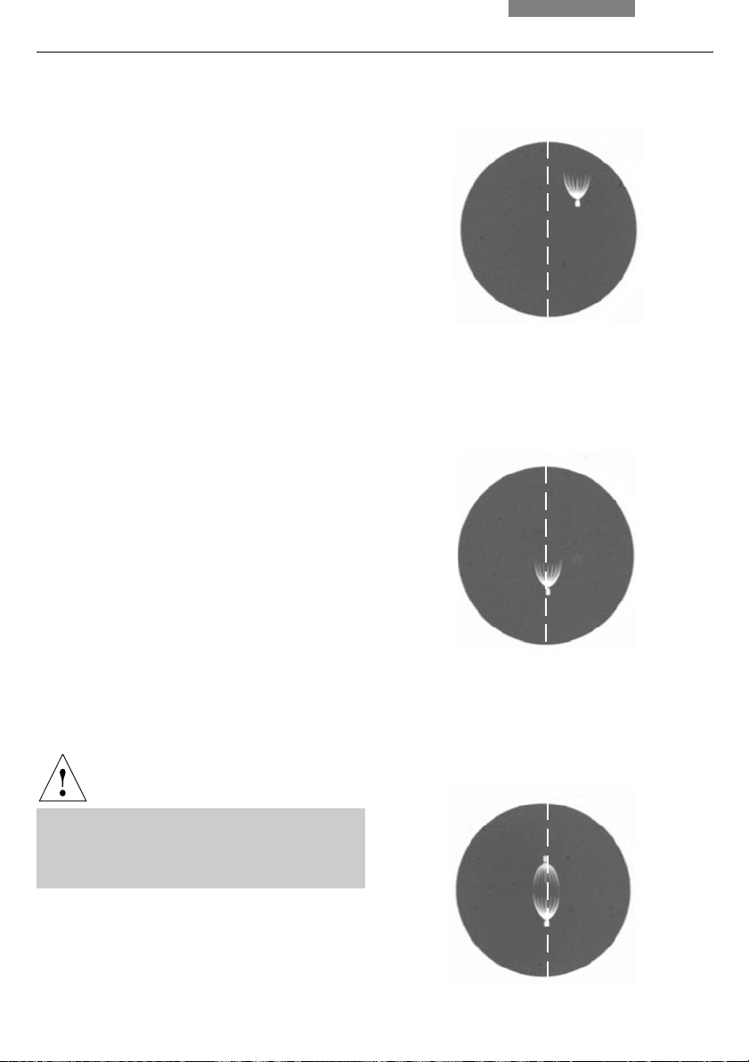
Fig. 29 Phase contrast centering procedure
PH=phase contrast ring, LR=light ring
a Condenser in bright field (BF) position
b Condenser in phase contrast (PH) position
Light ring (LR) not centered
c Light ring and phase ring centered
ab c
PH LR

7. Start-up
7.4 Adjusting the Light Sources
Centering is only required when using the 106z*
lamp housing.
• When a supply unit is used, it is turned on first
Caution!
Never look directly into the beam path!
Caution!
Light sources pose a potential irradiation
risk (glare, UV-radiation, IR-radiation).
For the 106z lamp housing, the direct arc image (for
gas discharge lamps) and its mirror image are
focused separately and adjusted to each other.
• Move the filter system* or reflector* into the
light path
• Open the shutter and remove any diffusing
screens* from the light path
• Put a piece of paper on the specimen stage
and roughly focus the surface with a dry
objective of low to medium magnification
• Set the field and aperture diaphragms roughly
at the center position
• With a felt or ballpoint pen, make a marking at
any position on the paper and slide it into the
small illuminated field
• Turn a vacant nosepiece position into the light
path or remove the objective
The light source will then be imaged onto the
paper. While observing the light source, the
lamp is adjusted as follows.
Fig. 30 106z lamp housing
1 Lamp height adjustment
2,4 Mirror image height and side adjustment
3 Focusing the reflector
5 Lamp side adjustment
6 Collector (focusing of the lamp image)
516
2
3
4
31
7. Start-up
Centering the Hg 50 W* Mercury Lamp
• On the paper, you see the direct arc image
and the mirror image, which in most cases are
not aligned
• Focus the direct image with the collector
(30.6)
• Use the adjusting buttons on the rear side of
the lamp housing (30.2, 30.4) to pivot the arc’s
mirror image to the side or completely out of
the beam path; the lamp filament’s focused
image remains visible (fig. 31)
• Use the adjusting buttons (30.1) and (30.5) to
place the direct arc image to the right or left
of an imaginary center line of the centering
plane (fig. 32).
• Then pivot the arc’s mirror image with the adjusting knobs (30.2 and 4) and focus it using
the reflector (30.3)
• Use the adjusting knobs (30.2 and 4) to orient
the mirror image symmetrically to the direct
image (fig. 33)
Fig. 31 Direct arc image focused but decentered
(in reality, the image is less focused)
Fig. 32 Direct arc image in target position
(in reality, the image is less focused)
• Defocus the image with the collector knob
(30.6) until the arc image and mirror image are
no longer recognizable and the image is
homogeneously illuminated
32
Fig. 33 Direct arc image and mirror image in target
position (in reality, the image is less focused)
7. Start-up
Centering the Hg 100 W* Mercury Lamps
as well as the Xe 75 W* Lamp
• On the paper, you see the direct arc image
and the mirror image, which in most cases are
not aligned
• Focus the direct image with the collector
(30.6)
• Use the adjusting buttons to pivot the arc’s
mirror image on the rear side of the lamp
housing (30.2, 30.4) to the side or completely
out of the beam path; the arc’s focused image remains visible (fig. 34)
• Use the adjusting buttons (30.1 and 5) to place
the direct arc image in the middle of the
centering plane, whereby the bright tip of the
arc, the focal spot, should lie slightly outside
the center (fig. 35)
• Then pivot the arc’s mirror image with the adjusting knobs (30.2) and (30.4) and focus it using the reflector (30.3)
Fig. 34 Direct arc image focused but not centered
(in reality, the image is less focused)
Fig. 35 Direct arc image in target position
(in reality, the image is less focused)
• Use the adjusting knobs (30.2 and 4) to orient
the mirror image symmetrically to the direct
image (fig. 36);
the V-shaped irradiation of the direct image
and mirror image arcs can be superimposed
Caution!
The bright tips of the arcs, the focal spots, must
never be projected onto each other, as this results in a danger of explosion by overheating.
Fig. 36 Direct arc image and mirror image in target
position (in reality, the image is less focused)
33

7. Start-up
Caution:
In older lamps, the structure of the arc is no
longer clearly recognizable. The image is
then more like that of a Hg 50 lamp. The image and mirror image can no longer be superimposed exactly. In this case, align both
images.
• Using the collector, defocus the image with
the knob (30.6) until the arc image and mirror
image are no longer recognizable and the image is homogeneously illuminated
34
8. Operation
8. Operation
8.1 Switching on
When using a gas discharge lamp*, the
external supply unit* must be turned on
separately.
Switch on the microscope at the on/off switch
(37.1).
8.2 Stages and Object Displacement
Lengthening the Coaxial Pinion (telescoping)*
For lengthening, pull the lower grip (38b.1)
downward. Repeat with the upper grip (38b.2).
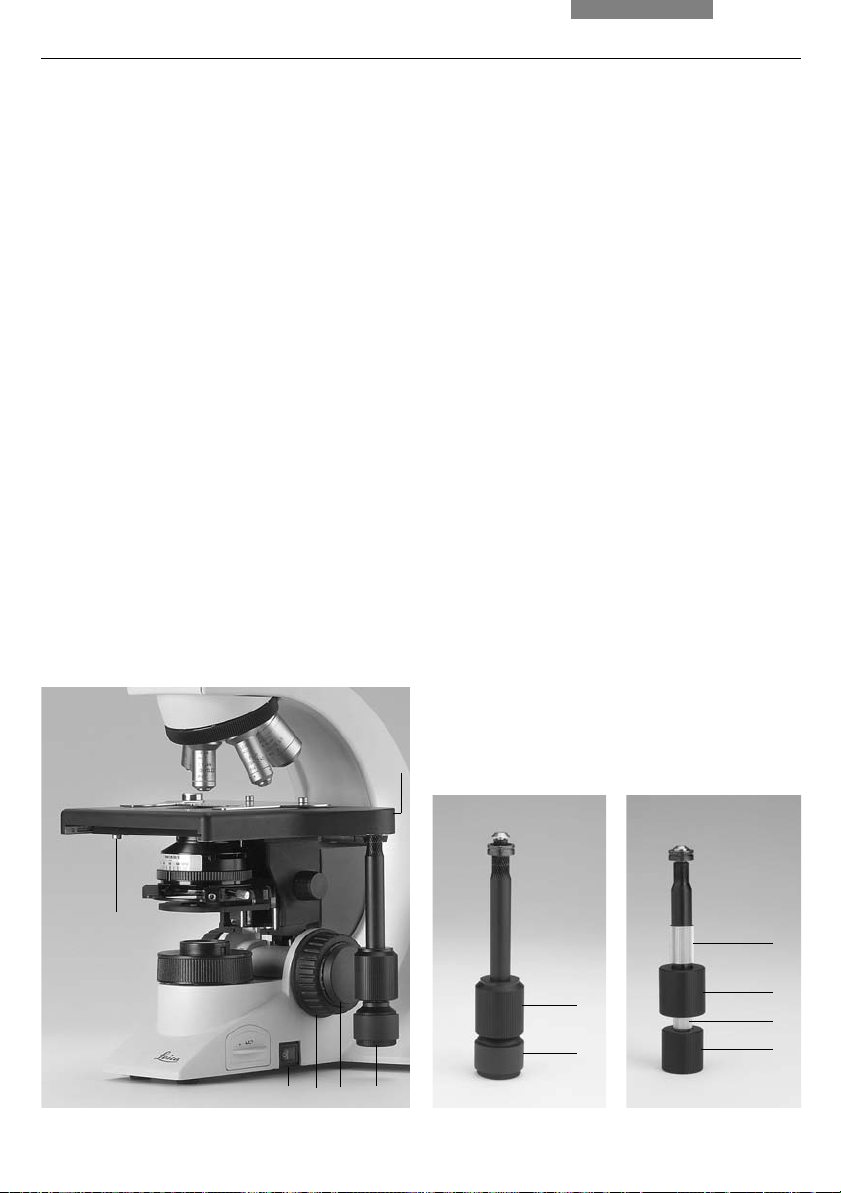
Fig. 37
1 On/off switch
2 Coarse focusing
3 Fine focusing
4 Stage positioning
5 Stage lock screw
6 Coaxial pinion mounting screw
Torque Adjustment*
The torque for x and y can be individually
adjusted using two knurled rings (38b.2, 38b.4).
Adjusting the Travel Range of the Stage
The travel range in e-w direction of the stage
could slightly decrease after a longer period of
working with the microscope. This can be
corrected as follows:
Move the object guide all the way to the left side
of the microscope to the current end of the
travel range with the coaxial pinion. Push one of
the screws which hold the object guide further
to the left with your hand as far as it will go.
Afterwards move the object guide all the way to
the right. Here also push the screw gently, this
time to the right, to the limit. The original travel
range of the stage is restored.
Fig. 38a Standard coaxial pinion, b coaxial pinion with
height and torque adjustment*
1 Object displacement (Y-direction)
2 Torque adjuster (X-direction)
3 Object displacement (X-direction)
6
4 Torque adjuster (Y-direction)
a
b
5
4
3
3
2
1
2
3
1 4
1
35
8. Operation
Right-/Left-hand Operation
The coaxial pinion can be attached to either
side of the stage (also see 6. Assembly, p. 16
onwards). To change the side, follow these
steps:
• Loosen the lock screw (37.5) at the bottom
left-hand side of the stage; the necessary tool
is attached to the bottom of the stage on the
right-hand side
!
Caution:
The condenser must be lowered!
• Slide the stage all the way back
• Release the screw (37.6) on the coaxial pinion
and pull the pinion out
• Place the flat fine focus wheel (37.3) on the
side to which you intend to mount the coaxial
pinion; the wheel is held in place
magnetically; ensure that the button snaps
into place. Attach the other focus knob on the
opposite side
8.3 Focusing
Coarse and Fine Focusing
Coarse and fine focusing wheels are located on
either side of the stand (fig. 37 and 39).
The special form of the flat fine focus wheel
(37.3) lets users enclose the coaxial pinion in
their hands while operating the fine focus with
one finger. The flat wheel should therefore be
mounted onto the appropriate side.
See right-/left-hand operation of the stage.
Height Adjustment of the Focusing Wheels
• Defocus the image by moving the stage down
with a full turn of the coarse focus wheel
(37.2, 39.1)
• Grasp the right-hand and left-hand focus
knobs at the same time and press the knobs
gently upward or downward into the desired
position
• Refocus the image
• Fasten the coaxial pinion to the other side of
the stage by retightening the appropriate
screw.
• Return the stage to the starting position and
retighten the lock screw; after installation of
the stage control, move object guide all the
way to the left side of the instrument; keep
turning when guide has reached the end of
travel until a click noise is heard
• Readjust the condenser
36
Fig. 39 Focus knob with scale
1 Coarse focusing
2 Fine focusing
1
2
8. Operation
8.4 Tubes
Note:
Close any unused tube openings, as otherwise
stray light can interfere with observation.
Adjusting the Viewing Distance
Adjust the viewing distance of the eyepieces
so that a congruent total image is seen (fig. 40).
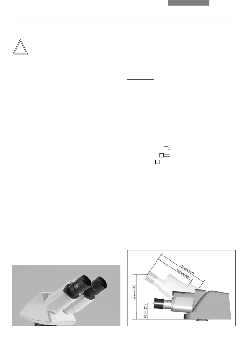
Adjusting the Viewing Angle
• For the HC LVB 0/4/4 and HC -/0/4 ergonomy
tubes*, the viewing angle can be adjusted by
tilting the binocular viewer
Ergotube (long, swivelable): 0° - 35°
Ergotube (short, swivelable): 7.5° - 32.5°
• For the AET22 and EDT22 ergotubes*, the
viewing angle can be adjusted by tilting the
binocular viewer in the range of 5° - 32° (fig. 41)
Adjusting the Eyepiece Section to the Arm
Length
• On the AET22 tube, the eyepieces can be
extended up to 30 mm (fig. 41)
Beam Splitting in Photo Tubes*
EDT22 tube:
The beam splitting between the observation and
documentation outputs has a definite presetting
(50:50).
BDT P 25 tube:
The beam splitting is set manually by pulling out
a control bar.
Control Bar Observation Photo
VIS 100% 0%
50/50 150% 50%
PHOTO 110% 100%
Fig. 40 Tube setting
↔ Personal viewing distance of the eyepieces
↔
Fig. 41 With AET22* tube individual adjustments
37

8. Operation
HC L 2TU tube:
The beam splitting is set manually by pulling out
a control bar.
Control Bar Observation Photo
VIS 100% 0%
PHOTO 110% 100%
Fig. 42 Tube range HC L (extract)
1 Binocular observation tube HC LB 0/3/4
2 Ergonomy tube HC LVB 0/4/4, binocular,
viewing angle 0-35°
additional ergotube (short) HC -/0/4,
swivelable 7.5°-32.5°
3 Trinocular tube H L1T 4/5/7, with fixed beamsplitter
(50%/50%)
4 HC L1VT 0/4/4 like 3,
but with adjustable viewing angle of 0-35°
5 Photo adapter, with 2 exits (50%/50%)
6 Photo TV exit
1
2
8.5 Eyepieces
Note:
The eyepiece’s aperture protector must be
removed or folded back during microscopy
while wearing eyeglasses.
We recommend
that users remove their glasses
with bifocal or progressive-addition lenses
when working with the microscope.
For the adjustable tubes with documentation
output, choose the 100% VIS position.
Eyepieces with Inlaid Reticle*
• Focus the reticle by adjusting the eyelens
• Focus on the object through this eyepiece
• Then, close that eye and focus on the object
by adjusting only the second ocular
Correction for Vision Problems
• With your right eye, look through the right
eyepiece and bring the specimen into sharp
focus
• Then, with your left eye, view the same
specimen and rotate the left eyepiece tube
until the object is brought into sharp focus;
do not use the focus dial
38
34
56

8.6 Objectives
Changing Objectives
8. Operation
Caution!
The objective must be moved manually into the
light path. Be sure that the nosepiece turret
locks into place.
When you rotate the objective into position, the
settings for
• Field diaphragm → p. 41
• Aperture diaphragm → p. 40
• Light intensity → p. 40
should be checked.
• For immersion objectives use the appropriate
immersion medium.
OIL: Only use optical immersion oil
according to DIN/ISO standards,
cleaning → p. 55
W: Water immersion
IMM: Universal objective for water, glycerol,
oil immersion
Follow safety instructions for immersion oil!
Note:
For lockable immersion objectives lock these by
pushing the front part upwards until it stops
(approx. 2 mm). Then, after a gentle turning
motion to the right, the objective is locked
(Fig. 44).
For objectives with corrective mounts turn the
knurl to adjust the objective to the thickness of
the cover glass.
Fig. 43 Immersion objective (released) Fig. 44 Immersion objective (locked)
↔
↔
39
8. Operation
8.7 Light sources
Transmitted light
Adjust the brightness with the dial (45.1).
The numbers on the dial are not absolute values,
but are intended to enable reproducible
settings.
Note:
The
HI PLAN xx SL* and
HI PLAN CY xx SL*
(Synchronized Light) objective lines permit
objectives to be changed without having to
adjust the light intensity in addition.
Fluorescence*
Switch on the lamp at the external power unit.
Caution!
8.8 Aperture Diaphragm
The aperture diaphragm (46.3) determines the
resolution, depth of field and contast of the
microscope image. The best resolution is
obtained when the apertures of the objective
and the condenser are roughly the same.
When the aperture diaphragm is stopped down
to be smaller than the objective aperture,
resolving power is reduced, but the contrast is
enhanced. A noticeable reduction in the
resolving power is observed when the aperture
diaphragm is stopped down to less than 0.6x of
the objective aperture and should be avoided
where possible.
In polarization microscopy, stopping down the
aperture diaphragm generally results in more
intense colors.
The aperture diaphragm is set according to the
viewer’s subjective impression of the image, the
scale on the dial is just to allow reproducible
settings and does not represent absolute
aperture values.
Keep the lamphousing at least 10 cm away
from the wall, curtains, wallpaper, books and
other combustible objects!
Fire Hazard!
Please read the separate documentation for the
supply unit.
40
Fig. 45
1 Brightness control
1

Color-coded Condenser
The color markings on the condenser (46.2)
correspond to the color rings of the objectives.
When changing objectives, a suitable aperture
diaphragm setting can easily be found by setting
it to the matching color marking (corresponds to
2/3 of the objective-side aperture).
Fig. 46 CL/PH condenser
1 Slot for light rings, etc.
2 Color coding
3 Aperture diaphragm
4 Filter holder
5 Field diaphragm
8. Operation
Attention:
The aperture diaphragm in the illumination light
path is not for setting the image brightness. Only
the rotary brightness adjustment knob or the
neutral density filter should be used for this.
An aperture diaphragm in the objective is
normally fully opened. The reduction in image
brightness caused by stopping down results in:
Greater depth of field
Less coverglass sensitivity
Suitability for darkfield
Change in contrast
8.9 Field diaphragm
The field diaphragm (46.5) protects the
specimen from unnecessary warming and keeps
all light not required for image formation away
from the object to enable greater contrast. It is
therefore only opened just wide enough to
illuminate the viewed or photographed object
field. A change in magnification therefore
always necessitates matching of the field
diaphragm.
1
2
3
4
5
41

9. Contrast Methods
9. Contrast Methods
9.1 Transmitted Light
Objective Magnification 2.5 x*
The CL/PH and CLP/PH condensers can be used
alone starting at 4x magnification.
When using a diffuser slider*, 2.5x magnifi-
cation is also possible; not when using polarization, however.
The UCL and UCLP condensers can also be used
alone starting at 4x magnification.
When using an adapter lens* (in the condenser
disk), 2.5x magnification is also possible.
Before using the adapter lens, set Köhler
illumination (→ p. 28) with 4x or 10x objective.
Switch over to objective 2.5x, engage the lens,
open the aperture diaphragm as far as the stop
and narrow the field diaphragm.
In case of arc-shaped vignetting, center the
lens: insert both centering keys into the
condenser at an angle from the back and adjust
until the asymmetrical vignetting disappears.
Remove the centering keys and open the field
diaphragm.
The lens can only be used up to an objective
magnification of max. 20x. Exact Köhler
illumination can no longer be obtained!
The Achr.Apl.0.9 (P) condenser can be used
alone starting at 4x magnification.
With the condenser head swung out, 2.5x
objective magnification is possible without a diffuser; with the head swung in, the diffuser must
be in place (max. eyepiece field number 22).
Objectives with magnifications < 10x are used
with the condenser head folded out, magnifications of 10x upwards (up to 100x) with the
condenser head folded in.
With the use of the switchable polarizer (11 555
034) and by swinging-out the blue filter (11 505
210 or 11 505 211) you need to unscrew the outer
longer condenser lever.
The optional diffuser* (11 505 219) resp. the
condenser lens* (11 505 507) for lower objective
magnifications (1.25x–5x) is placed with the
opening on the condenser top. The diffuser/
condenser lens* will be automatically switched
into the light path when the condenser top is
swung out by use of the objective magnifications lower than 10x.
Magnifications of 1.6x and 2.5x are also
possible with the CL/PH or CLP/PH, UCL or UCLP
condensers if the condenser is removed
completely. The field diaphragm then takes over
the function of the aperture diaphragm.
42
Note:
If the microscope is equipped for polarization,
the analyzer and polarizer as well as the lambda
plate compensator must be removed or swung
out when using other contrast methods.

9.1.1 Brightfield
• If present: click the condenser disk* into the
BF position
• If present: pull the light ring slide* out of the
condenser
• If present: switch the fluorescence illuminator
into an empty position or filter system A
9. Contrast Methods
• Insert a transmitted light specimen
• Rotate an appropriate objective into place
• Movable condenser heads:
The condenser top is swung out for
objective magnifications < 10x
• Bring the image into focus using the focus dial
and set the brightness
• For an optimal field diaphragm setting, check
the Köhler illumination (→
p. 31)
• Use suitable transmitted-light filters as
applicable (fig. 47)
Fig. 47 Filter holders*
DLF filter magazine for
attachment to microscope base
Filter holder with
two positions or one position for attachment to
microscope base
Filter holder for screw
attachment on the underside of the condenser
43

9. Contrast Methods
9.1.2 Phase Contrast*
• Insert a transmitted light specimen
• Rotate an appropriate objective into place;
objectives that are suitable for phase contrast
are engraved with PH
• Bring the image into focus using the focus dial
and set the brightness
• For an optimal field diaphragm setting, check
the Köhler illumination (→
• Open the aperture diaphragm completely
(position PH)
Condensers UCL/UCLP and UCA/P:
•
Set the light ring corresponding to the
objective on the condenser disk
Example: Light ring 1 belongs to the objective
with the engraving PH 1
Condensers CL/PH, CLP/PH, and
APL. ACHR.0.9 (P):
Use the light ring slide
p. 28)
9.1.3 Darkfield*
• Insert a transmitted light specimen
• Rotate an appropriate objective into place
• Bring the image into focus using the focus dial
and set the brightness
Condenser UCL/P:
•
Click the condenser disk into the BF position
Condensers CL/PH, CLP/PH, and
APL .ACHR.0.9 (P):
Pull out the DF light ring slide as far as the
stop;
check the Köhler illumination (→
• Open the aperture diaphragm completely
(position PH)
Condenser UCL/P:
•
Click the condenser disk into the DF position
Condensers CL/PH, CLP/PH, and
APL.ACHR.0.9 (P):
Insert the DF light ring slide as far as the stop
p. 28)
Note:
Condensers UCL/UCLP and UCA/P: Light rings
must be centered (→
44
p. 29).
Note:
Condensers UCL/UCLP and UCA/P: The DF light
ring must be centered (→
Special dark field condensers* are available for
the DM1000/DM1000 LED.
The application potential of the DF condensers
depends on the aperture of the objective in use.
For objectives with built-in iris diaphragm, the
aperture can be adapted.
DF condenser max. objective aperture
D 0.80 - 0.95 0.75
D 1.20 - 1.44 OIL 1.10
p. 29).

9. Contrast Methods
9.1.4 Oblique Illumination*
• First adjust transmitted light darkfield
• To obtain a relief-like contrast:
Condenser UCA/P:
Rotate condenser disk slightly out of the DF
position
Condensers CL/PH, CLP/PH, and
APL. ACHR.0.9 (P):
Push DF slide in part way out of the DF
position
9.1.5 Polarization*
• Swing the lambda plate of the lambda plate
compensator out if your microscope is
equipped with it
• Insert a specimen and rotate an appropriate
objective into place
• Bring the image into focus and set the Köhler
illumination (→
p. 28)
!
Attention!
Always use the polarizer with the labelled
side upward, as otherwise the integrated heat
protection filter is ineffective and the special
polarizer will become useless (discoloring!).
• Bring the polarizer and analyzer into cross position until they reach maximum darkness
• Remove the object or find an empty area of
the specimen
• Push the analyzer into the stand as far as
the 2nd clickstop or switch on the module
• Remove compensators from the light path if
your microscope is equipped with it
• Rotate the polarizer until you observe the
maximum extinction position in the
eyepiece (fig 48)
• Fix the cross position thus determined with
the clamping screw
• Depending on the equipment, the analyzer
may already have been inserted into the tube
mount during the assembly
Alternative:
If the analyzer mount TL* is used:
Insert the analyzer as far as the clickstop into
the microscope stand. The engraving λ must
be on the underside
When using the Pol intermediate tube*:
Switch on the analyzer
• Push the polarizer with the labelled side
upward into the lower opening
Fig. 48
Crossing the polarizers when observing through a focusing
telescope or Bertrand lens, high-aperture Pol objective
a exactly crossed, b not exactly crossed
Pos. a cannot be set if there is strain in the condenser or
objective, Pos. b is adequate for polarization contrast.
a
b
45

9. Contrast Methods
• If present:
Insert the λ or λ/4 compensator* into the filter
holder integrated in the condenser holder and
rotate to the left, roughly as far as the stop
CLP/PH condenser:
Insert the λ or λ/4 compensator into the slot
on the side of the condenser.
Condensers UCLP and UCA/P:
Rotate the condenser disk into position λ or
λ/4
9.2 Fluorescence*
• Insert a suitable specimen and rotate an
appropriate objective into place
• Focus the image initially in transmitted light if
appropriate
• Switch on the incident light source at the
external power unit
• Switch off the transmitted light illumination
• Open the shutter
• Select an appropriate fluorescence filter cube
• Switch magnification changer*, if present, to
factor 1x
• Disengage the BG 38 filter if there is no
disturbing red background; always engage
the filter for photography, however
Fig. 49 Leica DM1000 with
Fluorescence illuminator and 106z lamphousing
46

10. Measurements with the Microscope
10. Measurements with the Microscope
10.1 Linear Measurements
The following are required for linear measurements:
- Graticule with scale division* in eyepiece or a
digital linear measuring eyepiece*.
- Stage micrometer for calibration.
(→ fig. 50)
Micrometer Value
The micrometer value of the objective-eyepiece
combination used must be known before the
measurement, i.e. the distance in the specimen
that corresponds to the length of a division on
the graticule used.
Calibration:
• Align the stage micrometer and the graticule
parallel to each other by rotating the eyepiece
and adjust the zero marks of both scales to
exactly the same height
• Read how many scale divisions of the stage
micrometer correpond to how many on the
microscope scale (graticule)
Notes:
If using a magnification changer:
Remember to take the additional magnification
value* into consideration! We strongly recommend you calibrate each objective separately
instead of extrapolating the micrometer values
of the other objectives from the calibration of
one objective.
Measurement errors may occur if the eyepiece
is not pushed into the tube as far as the stop.
Particularly large object structures can also be
measured on the stage with the verniers (0.1 mm);
the distance to be measured could be calculated
from a combined x and y measurement.
Fig. 50
Scale division of the graticule in the eyepiece (left)
and image of the stage micrometer (right)
• Divide the two values; the result is the
micrometer value for the total magnification
that has just been used
Example:
If 1.220 mm of the stage micrometer corresponds to 100
divisions of the measurement scale, the micrometer
value is 1.220:100 = 0.0122 mm = 12.2 μm. For extremely
low objective magnifications it may be that only part of
the measurement scale can be used for calibration.
47

10. Measurements with the Microscope
10.2 Thickness Measurements
In principle, thickness measurements can be
carried out if both the upper and the lower
surface of the object can be clearly focused.
The difference in stage height setting (fine
focus knob: distance between two divisions =
approx. 3 μm) gives a value for transmitted light
objects that is falsified by the refractive index of
the object (which has been "transfocused") and
perhaps immersion oil. The true thickness of the
object detail measured in transmitted light is
given by the vertical stage movement (focusing
difference) d’ and the refractive indices n
object and n
of the medium between the
i
of the
o
coverglass and the objective (air = 1).
n
0
d = d'
n
i
Example:
The upper and lower surfaces of a thin polished
specimen have been focused with a dry
objective (n
= 1.0), scale readings of the
i
mechanical fine drive (division spacing = 3 μm):
9.0 and 27.0.
Therefore d’ = 18 x 3 = 54 μm.
The refractive index of the object detail was
taken to be n
= 1.5.
o
Thickness d = 54 x 1.5 / 1 = 81 μm.
Object Marker*
The object marker is screwed instead of an
objective. When rotated, a diamond is lowered
onto the coverglass or object surface, where
circles of variable radii can be scribed to mark
objects.
48
10. Measurements with the Microscope
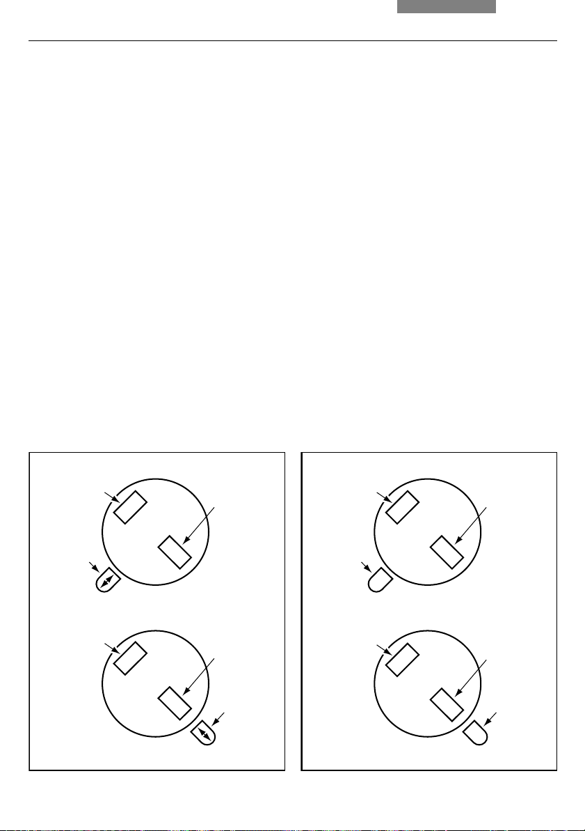
10.3 Differentiation of Gout / Pseudo Gout
The use of the lambda plate compensator* is a
prerequisite for this test.
Assembly → p. 24.
Orienting the Lambda Plate Compensator
• Rotate the lambda plate compensator out of
light path (fig. 51)
• Bring the lambda plate compensator and
analyzer into cross position until they reach
maximum darkness (polarization → p. 45)
• Fix the cross position thus determined with
the clamping screw at the side (51.2)
• Swing in the lambda plate again
Fig. 51 Lambda plate compensator swung out
1 Orientation handle
2 Clamping screw
The following section explains the basic
procedure for gout/pseudo gout differentiation.
This test is made possible due to the negative
birefringence of urates and positive birefringence
of pyrophosphates. Both gout (monosodium urate)
and pseudo gout (calcium pyrophosphate) crystals
tend to be needle shaped. However, many
crystals may be broken and/or irregular. To do
the test, it is necessary to find at least one intact
crystal orientated on same axis as orientation
handle and one per-pendicular to axis.
Procedure
To insure the test is being done correctly, a slide
of known monosodium urate crystals should be
used initially.
• Use of a 40x objective is recommended
• Swing the lambda plate out of the path of light
(fig. 51)
• Place the slide on the stage and bring crystals
into a sharp focus; the needle shaped crystals
will appear white regardless of orientation
90°
• Swing in the lambda plate and put the
orientation handle (51.1) into it’s extreme left
position; crystals with a long dimension in the
handle direction should appear yellow and
the perpendicular to handle direction blue
(fig. 52)
2
1
49
10. Measurements with the Microscope
• Move the orientation handle to its extreme
right position; now the aligned crystals should
be blue, and perpendicular yellow (fig. 52)
• Be sure to test crystals with the orientation
handle in each position to insure positive
identification
Fig. 52 Identification of gout
Test for Gout
Crystals
yellow
Crystals
blue
The following is the procedure for identification of pseudo gout:
The test for pseudo gout is done identically to
the test for gout. However, the color change is
opposite that of Gout. That is, with the handle at
the left extreme, aligned crystals are blue and
perpendicular crystals are yellow, and vice
versa with the level at the right side (fig. 53).
Fig. 53 Identification of pseudo gout
Test for Pseudo Gout
Crystals
blue
Crystals
yellow
50
Handle
left
Crystals
blue
Crystals
yellow
Handle
right
Handle
left
Crystals
yellow
Crystals
blue
Handle
right

11. Trouble shooting
11. Trouble shooting
Problem
Stand
The microscope does not respond.
Illumination
The image is completely dark.
Cause/Remedy
Make sure that voltage is available
Make sure that the stand is connected to the
power supply
Check the cable connections
Check whether the fuse is defective and
replace it if necessary (→
p. 55)
Transmitted light:
Ensure that the lamp in the integrated
transmitted light illumination is not defective;
lamp replacement (→
p. 20)
Fluorescence:
Open the shutter (→
Make sure that the lamps are connected to
p. 46)
the power supply and that they are not
defective. Lamp replacement (→
Inform Leica Service and have the supply unit
p. 21 onwards)
fuse checked
The image is unevenly or not uniformly
illuminated.
The illumination "flickers."
Remove all unneeded filters from the light
path
Center the lamp (106 z lamp housing)
p. 31 onwards).
(→
Replace the old lamp (→
Be sure that there is no loose connection at
p. 20 onwards)
the power supply
Replace the old lamp (→
p. 20 onwards)
51

11. Trouble shooting
Problem
Fluorescence: The lamp does not illuminate
immediately upon being switched on.
Focus
The specimen cannot be brought into focus.
Darkfield
No definite DF contrast is possible.
Cause/Remedy
The external power supply must be switched
on repeatedly
Hot Hg lamps should cool down before
switching on again
Use the correct immersion medium
Lay the specimen with the cover glass to-
wards the top
Make sure that the cover glass thickness is
correct and that it suits the indication on the
objective
Be sure that a DF objective is being used
The objective aperture setting is too high
(maximum 0.75/1.10); if necessary, reduce the
objective aperture using the iris diaphragm on
the objective
Check the condenser centering
Open the aperture diaphragm completely
The image is unevenly or not uniformly
illuminated.
Undesirable stray light.
Polarization
No polarization contrast is possible.
52
The magnification is too weak. Use a higher
magnification
Clean the specimen and neighboring lenses
p. 54)
(→
Bring the polarizer and analyzer into cross po-
sition until they reach maximum darkness
(without specimen) (→ p. 45)

11. Trouble shooting
Problem
Phase Contrast
No phase contrast is possible.
Fluorescence
The image is completely dark (no fluorescence).
The fluorescence is too weak.
Cause/Remedy
The specimen is too thick, too thin or too
brightly stained
Refractive index of mounting medium and
specimen is identical so that there is no phase
jump
The cover glass is not placed evenly
Check the right light ring (→ p. 44)
Check the centering of the light rings
(→ p. 29-30)
Check the condenser centering
Open the aperture diaphragm completely
Open the shutter (→
Check the antigen-antibody combination
Insert a new lamp (→
Center the lamp (→
Insert a new lamp (→
p. 46)
p. 21 onwards)
p. 31 onwards)
p. 21 onwards)
Stage
Travel range of the stage in e-w direction
decreases after a longer period of working.
Move the stage all the way to the left side
with the coaxial pinion
Push one of the screws which hold the object
guide with your hand further to the left as far
as it will go
Afterwards move the stage all the way to the
right
Push one of the screws which hold the object
guide with your hand further to the right as far
as it will go
53
12. Care of the Microscope
12. Care of the Microscope
12.2 Cleaning
Caution!
Unplug the power supply before performing
cleaning and maintenance work!
Protect electrical components from moisture!
Microscopes in warm and warm-damp climatic
zones require special care in order to prevent
fungus contamination.
The microscope should be cleaned after each
use, and the microscope optics should be kept
extremely clean.
12.1 Dust Cover
Note:
To protect against dust, cover the microscope and
accessories with the dust cover after each use.
Caution!
Let lamps cool down before covering the
stand with a dust cover. The dust cover is
not heat-resistant. In addition, condensation
may occur.
Caution:
!
Residual fiber and dust can create unwanted
background fluorescence.
Cleaning Coated Parts
Dust and loose dirt particles can be removed
with a soft brush or lint-free cotton cloth.
Clinging dirt can be cleaned with a little soapy
water, benzine or ethyl alcohol.
For cleaning coated parts, use a linen or leather
cloth that is moistened with one of these substances.
!
Caution:
Acetone, xylene or nitro-containing thinner
can harm the microscope and thus may not
be used.
Test clean solutions of unknown composition
first on a less visible area of the unit. Be sure
that coated or plastic surfaces do not become
matted or etched.
54

12. Care of the Microscope
Cleaning glass surfaces and objectives
Glass surfaces, and particularly objectives, are
always to be cleaned as described in the
brochure "Cleaning of Microscope Optics". You
can download the information from
http://www.leica-microsystems.com/products/
light-microscopes/clinical/uprightmicroscopes/details/product/leica-dm1000-led/
downloads/
or contact our Technical Service with any
questions.
Removing Immersion Oil
Caution!
Follow safety instructions for immersion oil!
First, wipe off the immersion oil with a clean
cotton cloth, and then re-wipe the surface
several times with ethyl alcohol.
12.3 Handling Acids and Bases
For examinations using acids or other aggressive chemicals, particular caution must be
taken.
Caution:
!
Never allow the optics and mechanical parts
to come into contact with these chemicals.
12.4 Changing Fuses (DM1000)
The fuse module (fig. 54) at the back of the stand
can be removed with a sharp object.
Fuse data→ p. 8, 56
Order no.→ p. 56
Caution!
Never use any fuses as replacements other
than those of the types and the current ratings listed here. Using patched fuses or
bridging the fuse holder is not permitted. The
use of incorrect fuses may result in a fire
hazard.
Fig. 54
Fuse module
(DM1000)
55

13. Essential Wear and Spare Parts
13. Essential Wear and Spare Parts
Order No.
Material No. Name Used for
Replacement Lamp
11 500 317 Halogen lamp 12 V 30 W integrated illumination (DM1000)
11 500 974 Halogen lamp 12 V 100 W 107/2 lamp housing
11 500 137 High-pressure mercury burner 50 W 106 z lamp housing
11 500 138 High-pressure mercury burner 100 W 106z lamp housing
11 500 321 High-pressure mercury burner 100 W 106z lamp housing
11 500 139 High-pressure xenon burner 75 W 106z lamp housing
Screw cap for unused objective receptacles
11 020 422 570 000 Screw cap M 25 objective turret
Replacement eyecup (diaphragm protection) for HC PLAN eyepiece
11 021 500 017 005 HC PLAN eyecup 10x/25 eyepiece
11 021 500 017 005 HC PLAN eyecup 10x/22 eyepiece
11 021 264 520 018 HC PLAN eyecup 10x/20 eyepiece
(103 W/2)
Immersion Oil as per ISO 8036/1, refraction index n23 = 1.5180 ± 0.005, dispersion v23 = 44 ± 2
11 513 859 10 ml, free of natural fluorescence OIL and IMM objectives
11 513 860 20 ml and oil condenser heads
11 513 861 250 ml
Fuses
11 826 365 F 3.15 A 250 V Fuse for microscope stand (DM1000)
Rechargeable batteries
11 505 249 Pack of rechargeable batteries Leica DM1000 LED
e
e
56
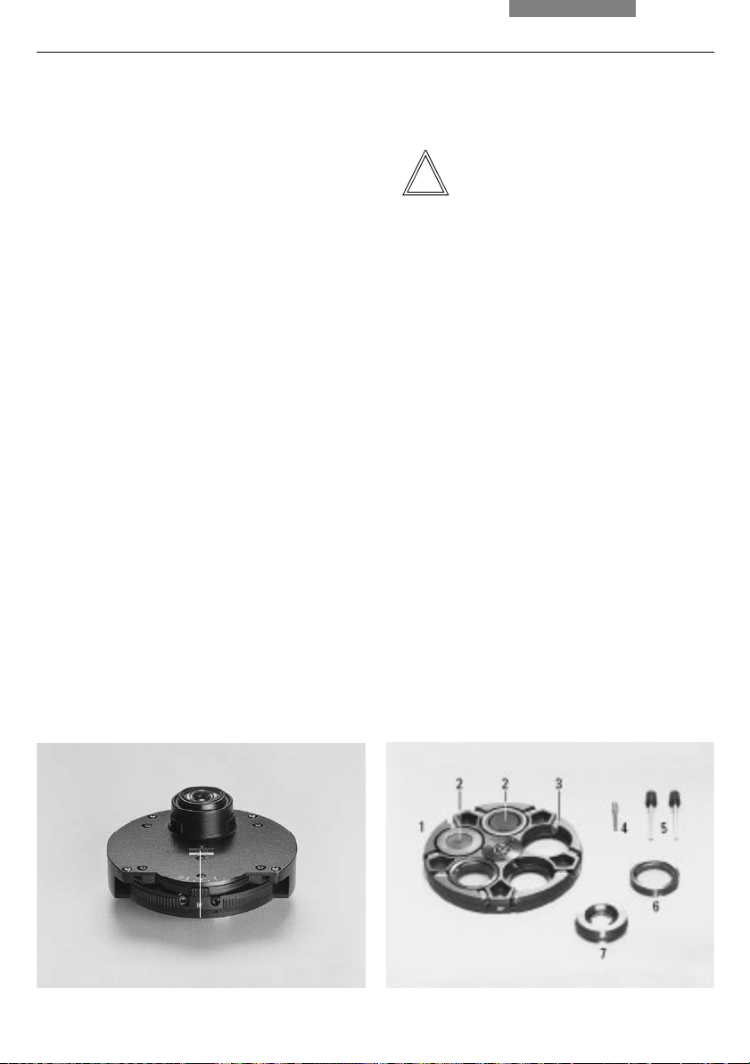
14. Retrofitting Components
14. Retrofitting Components
14.1 Equipping the Condenser Disk*
• Turn the stage upwards and lower the
condenser
• Remove the condenser by loosening the
condenser’s clamping screw
Condenser UCL/UCLP*
• Loosen the screw (55.1) completely
• Turn back the centering screws until the light
rings*, λ - and λ/4 - compensator* and lens*
2.5x can be inserted;
the largest hole is for brightfield
observation (= BF), the slightly smaller ones
are for light rings, λ - and λ/4 - compensator
or lens* 2.5x
Fig. 55 Condenser UCL
1 Fixing screw for condenser disk
Notes:
If you use a smaller hole for brightfield, the
maximum illumination aperture cannot be used.
The lettering (e.g. DF, PH 1 ....., λ) must point
upward, the λ or λ/4 compensators must be
inserted with the correct orientation: The notch
must point towards the center of the disk! The
lettering of the components should
to
the marking at the opposite position (outer
correspond
edge of the disk).
• Tighten the centering screws until the
components are roughly in the center of the
holes
Fig. 56 UCL condenser disk
1 Condenser disk
2 Light ring or λ− or λ/4-compensator
3 Centering screws
4 Axis
5 Centering keys
6 λ- orλ/4-plate
7 Auxiliary lens
1
57

14. Retrofitting Components
Attention:
Before fitting the disk into the condenser, make
sure that neither of the centering screws is
sticking out at the side.
• Fasten the condenser disk with the axis
screw, check that the disk rotates properly
through 360°
• If present, screw the condenser head into the
condenser and affix the condenser with the
condenser's clamping screw
Condenser UCA/P*
• Unscrew the fastening screw of the disk. This
is found on the underside of the condenser
and must be fully screwed out
• Turn back the centering screws until the light
rings, λ - and λ/4 - compensator* and lens*
2.5x can be inserted;
the largest hole is for brightfield
observation (= BF), the slightly smaller ones
are light rings*, λ - and λ/4 - compensator*
or lens* 2.5x.
Notes:
!!
Attention:
Before fitting the disk into the condenser, make
sure that neither of the centering screws is
sticking out at the side.
• Fasten the condenser disk with the axis
screw, check that the disk rotates properly
through 360°
• If present, screw the condenser head into the
condenser and affix the condenser with the
condenser's clamping screw
Fig. 57 UCA/P condenser disk
1 Light ring "small, PH"
2 Light ring "large" for large holes
3 a, b DIC condenser prism
4 Marking for assembly of DIC condenser prisms
5 Marking K on the prism mount
6 Guide groove for prism
7 Adhesive label
8 Centering screws
9 Rotatable axis
10 λ or λ/4 compensator
If you use a smaller hole for brightfield, the
maximum illumination aperture cannot be used.
The lettering (e.g. DF, PH 1 ....., λ) must point
upward, the λ or λ/4 compensators must be
inserted with the correct orientation: The notch
must point toward the center of the disk! The
lettering of the components should
to
the marking at the opposite position (outer
correspond
edge of the disk).
58

15. Index
15. Index
106z Lamp Housing 21, 31
Adapter lens 42
Adjusting the light sources 31
Ambient conditions 14
Analyzer 19, 24, 45
Analyzer mount TL 19, 24, 45
Aperture diaphragm 40, 41
Auxiliary condenser lens LS 18
Battery operation 27
Beam splitting 37
BG 38 46
Brightfield 43
Brightness 40
Camera 25
Care 54
Changing fuses 55
Changing objectives 39
Cleaning 54
Coarse focusing 36
Coaxial pinion 16, 35
Color-coded condenser 41
Compensators 45, 46
Condenser 11, 18
Condenser centering 29
Condenser disk 57
Condenser head 28, 43
Condenser height adjuster 18, 29
Condenser holder 18
Connection to the power supply 27
Contrast method 10
Corrective mounts 39
Cross position 45
Darkfield 44
DLF filter magazine 43
Dust cover 54
Electrical safety 8
Ergolift 26
Ergomodule 26
Eyepiece section 37
Eyepieces 19, 38
Field diaphragm 41
Filter holder(s) 24, 41, 43
Fine focusing 36
Fluorescence 46
Fluorescence filter cube 46
Fluorescence illuminator 21
Focusing 36
Focusing telescope 30
Focusing wheels 36
Fuse 56
Gas discharge lamps 21, 22, 23
Gout / Pseudo gout 49
Heat protection filter 45
Height adjustment of the focusing
wheels 36
Hg 100 W mercury lamps 33
Hg 50 burner 22
Hg 50 W mercury lamp 32
Immersion objective 39
Immersion oil 39, 55, 56
Inlaid reticle 38
Installation location 14
Integrated illumination 20
Intermediate tube pole 19, 24
Köhler illumination 28
Lambda plate 45, 46
Lambda plate compensator 24, 49
Lengthening the coaxial pinion 35
Light intensity 40
Light ring 29, 41, 44
Light ring centering 30
Light ring slide 29, 44
Light sources 40
Linear measurements 47
Magnification changer 26
Micrometer value 47
Object displacement 35
Object marker 48
Objective magnification 2.5 x 42
Objective turret 10
Objectives 19, 39
Oblique illumination 45
Phase contrast 44
Phase contrast rings 29
Pol intermediate tube 45
Polarization 45
Polarizer 24, 45
Polarizer holder 24
Replacement lamp 56
Replacing the lamp 20
Right-/left-hand operation 36
Safety notes 8
Shutter 46
Spare parts 56
Specifications 8
Specimen holder 16
Stage 16, 35
Supply unit 21, 35
Thickness measurements 48
Torque 35
Tracing device 27
Transmitted light 42
Transmitted light filter 43
Transmitted light illumination 20
Transport 15
Trouble Shooting 51
Tube 19, 37
Tube openings 37
Tube range 38
Viewing angle 37
Viewing attachments 26
Viewing distance 37
Vision problems 38
Xe 75 burner 22, 33
59

16. EC Declaration of Conformity
16. EC Declaration of Conformity
Download:
http://www.leica-microsystems.com/products/light-microscopes/clinical/upright-microscopes/
details/product/leica-dm1000/downloads/
http://www.leica-microsystems.com/products/light-microscopes/clinical/upright-microscopes/
details/product/leica-dm1000-led/downloads/
60

Leica DM1000
Leica DM1000 LED
Bedienungsanleitung

Copyrights
Copyrights
Alle Rechte an dieser Dokumentation liegen bei
der Leica Microsystems CMS GmbH. Eine Vervielfältigung von Text und Abbildungen – auch
von Teilen daraus – durch Druck, Fotokopie, Mikrofilm oder andere Verfahren, inklusive elektronischer Systeme, ist nur mit ausdrücklicher
schriftlicher Genehmigung der Leica Microsystems CMS GmbH gestattet.
Die in der folgenden Dokumentation enthaltenen
Hinweise stellen den derzeit aktuellen Stand der
Technik dar. Die Zusammenstellung von Texten
und Abbildungen haben wir mit größter Sorgfalt
durchgeführt. Trotzdem kann für die Richtigkeit
des Inhaltes dieses Handbuches keine Haftung
irgendwelcher Art übernommen werden. Wir
sind jedoch für Hinweise auf eventuell vorhandene Fehler jederzeit dankbar.
Die in diesem Handbuch enthaltenen Informationen können ohne vorherige Ankündigung geändert werden.
4

Inhalt
Inhalt
1. Wichtige Hinweise zur Anleitung ......... 6
2. Zweckbestimmung des Mikroskops..... 7
3. Sicherheitshinweise ................................ 8
3.1 Allgemeine Sicherheitshinweise............ 8
3.2 Elektrische Sicherheit .............................. 8
3.3 Entsorgung.................................................. 9
4. Geräteübersicht ........................................ 10
5. Auspacken .................................................. 14
6. Montage des Mikroskops ....................... 16
6.1 Objekttisch .................................................. 16
6.2 Kondensor ................................................... 18
6.3 Tubus und Okulare..................................... 19
6.4 Objektive ..................................................... 19
6.5 Lichtquelle für die Durchlichtachse ...... 20
6.6 Komponenten für
Fluoreszenzanwendungen ....................... 21
6.6.1 Fluoreszenzilluminator ................... 21
6.6.2 Lampenhaus 106z ........................... 21
6.7 Analysator und Polarisator ..................... 24
6.8 Lambda-Plattenkompensator .................. 24
6.9 Optionales Zubehör ................................... 25
6.10 Einsetzen der Akkus .................................. 27
6.11 Anschluss an die Stromversorgung ....... 27
7. Inbetriebnahme ......................................... 28
7.1 Einschalten ................................................. 28
7.2 Köhlersche Beleuchtung ......................... 28
7.3 Phasenkontrastringe überprüfen ........... 29
7.4 Justieren der Lichtquellen ....................... 31
8. Bedienung .................................................. 35
8.1 Einschalten ................................................. 35
8.2 Tische und Objektverschiebung ............. 35
8.3 Fokussierung .............................................. 36
8.4 Tuben ........................................................... 37
8.5 Okulare ........................................................ 38
8.6 Objektive ..................................................... 39
8.7 Lichtquellen ................................................ 40
8.8 Aperturblende ............................................ 40
8.9 Leuchtfeldblende ....................................... 41
9. Kontrastverfahren ..................................... 42
9.1 Durchlicht ................................................... 42
9.1.1 Hellfeld .............................................. 43
9.1.2 Phasenkontrast ............................... 44
9.1.3 Dunkelfeld ........................................ 44
9.1.4 Schiefe Beleuchtung ..................... 45
9.1.5 Polarisation ...................................... 45
9.2 Fluoreszenz ................................................. 46
10. Messungen mit dem Mikroskop ............ 47
10.1 Längenmessungen .................................... 47
10.2 Dickenmessungen ..................................... 48
10.3 Differenzierung
von Gicht/Pseudogicht ............................. 49
11. Problembehandlung ................................. 51
12. Pflege des Mikroskops ............................ 54
12.1 Staubschutz ................................................ 54
12.2 Reinigung .................................................... 54
12.3 Umgang mit Säuren und Basen .............. 55
12.4 Sicherungswechsel .................................. 55
13. Wichtigste Verschleiß-
und Ersatzteile ........................................... 56
14. Nachrüstungen .......................................... 57
14.1 Bestücken der Kondensorscheibe ......... 57
15. Index ............................................................ 59
16. EU-Konformitätserklärung ...................... 60
5
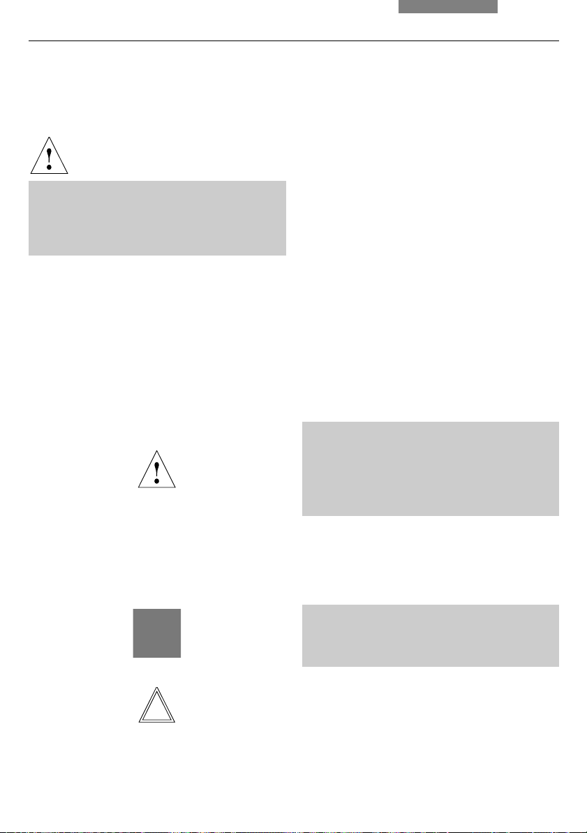
1. Wichtige Hinweise zur Anleitung
1. Wichtige Hinweise zur Anleitung
Achtung!
Diese Bedienungsanleitung ist ein wesentlicher Bestandteil des Mikroskops und muss
vor Montage, Inbetriebnahme und Gebrauch
sorgfältig gelesen werden.
Textsymbole, Piktogramme und ihre Bedeutung:
(1.2)
→
S. 20
!
Diese Bedienungsanleitung enthält wichtige Anweisungen und Informationen für die Betriebssicherheit und Instandhaltung des Mikroskops
und der Zubehörteile. Sie muss daher sorgfältig
aufbewahrt werden.
Ziffern in Klammern, z.B. (1.2), beziehen sich auf
Abbildungen, im Beispiel Abb.1, Pos. 2.
Ziffern mit Hinweispfeil, z.B. → S. 20, weisen auf
eine bestimmte Seite dieser Anleitung hin.
Achtung!
Besondere Sicherheitshinweise in dieser
Anleitung sind durch das nebenstehende
Dreieckssymbol gekennzeichnet und grau
unterlegt.
Achtung! Bei einer Fehlbedienung können Mikroskop bzw. Zubehörteile beschädigt werden.
Hinweise zur Entsorgung des Gerätes, von
Zubehörkomponenten und Verbrauchsmaterial.
Erklärender Hinweis
*
6
Nicht in allen Ausrüstungen enthaltene Position

2. Zweckbestimmung des Mikroskops
2. Zweckbestimmung des Mikroskops
Das Mikroskop Leica DM1000/DM1000 LED, zu
dem diese Bedienungsanleitung gehört, ist für
biologische Routine- und Forschungsanwendungen vorgesehen. Dies schließt die Untersuchung von aus dem menschlichen Körper
stammenden Proben zum Zwecke der
Informationsgewinnung über physiologische
oder pathologische Zustände oder angeborene
Anomalien oder zur Prüfung auf Unbedenklichkeit und Verträglichkeit bei potenziellen Empfängern oder zur Überwachung therapeutischer
Maßnahmen ein.
Für jegliche nicht-bestimmungsgemäße Verwendung und bei Verwendung außerhalb
der Spezifikationen von Leica Microsystems
CMS GmbH, sowie gegebenenfalls daraus
entstehender Risiken übernimmt der Hersteller keine Haftung.
In solchen Fällen verliert die Konformitätserklärung ihre Gültigkeit.
Achtung!
Das oben genannte Mikroskop entspricht der
EG-Richtlinie 98/79/EG über In-vitro-Diagnostika.
(Gleichzeitig erfüllt das Gerät die EG-Richtlinien
2006/95/EG betreffend elektrische Betriebsmittel
und 2004/108/EG über die elektromagnetische
Verträglichkeit für den Einsatz in industrieller
Umgebung.)
Achtung!
Dieses (IVD-) Gerät ist nicht zur Verwendung
in der nach DIN VDE 0100-710 definierten
Patientenumgebung vorgesehen. Es ist auch
nicht zur Kombination mit Medizingeräten
nach der EN 60601-1 vorgesehen. Wird ein
Mikroskop mit einem Medizingerät nach EN
60601-1 elektrisch leitend verbunden, so gelten die Anforderungen nach EN 60601-1-1.
Nicht geeignet zur Untersuchung von potenziell infektiösen Proben.
7
3. Sicherheitshinweise
3. Sicherheitshinweise
3.1 Allgemeine Sicherheitshinweise
Dieses Gerät der Schutzklasse 1 (DM1000)
bzw. 2 (DM1000 LED) ist gemäß
EN 61010-2-101:2002 (DM1000/DM1000 LED),
EN 61010-1:2001 (DM1000/DM1000 LED),
IEC 61010-1:2001 (DM1000/DM1000 LED),
IEC 60825-1:2007 (DM1000 LED)
EN 60825-1 + A1 + A2:2003 (DM1000 LED),
LED Klasse 1 (DM1000 LED)
Sicherheitsbestimmungen für elektrische Mess-,
Steuer-, Regel- und Laborgeräte gebaut und geprüft.
Achtung!
Um diesen Auslieferungszustand zu erhalten
und einen gefahrlosen Betrieb sicherzustellen,
muss der Anwender die Hinweise und Warnvermerke beachten, die in dieser Bedienungsanleitung enthalten sind.
Achtung!
Die in der Bedienungsanleitung beschriebenen Geräte bzw. Zubehörkomponenten sind
hinsichtlich Sicherheit oder möglicher Gefahren überprüft worden.
Bei jedem Eingriff in das Gerät, bei Modifikationen oder der Kombination mit Nicht-LeicaKomponenten, die über den Umfang dieser
Anleitung hinausgehen, muss die zuständige
Leica-Vertretung oder das Stammwerk in
Wetzlar konsultiert werden!
Bei einem nicht autorisierten Eingriff in das
Gerät oder bei nicht bestimmungsgemäßem
Gebrauch erlischt jeglicher Gewährleistungsanspruch sowie die Produkthaftung!
3.2 Elektrische Sicherheit
Allgemeine technische Daten
Mikroskop
Verwendung nur in Innenräumen.
Versorgungsspannung:
Leistungsaufnahme:
Sicherungen:
Umgebungstemperatur:
Relative Luftfeuchtigkeit:
Überspannungskategorie:
Verschmutzungsgrad:
Technische Daten des externen Netzteils
Stromversorgung ELPAC POWER SYSTEMS,
Model: FW1812
Input: 100-240 V AC
0,5 A
47-63 Hz
Output: 12 V DC
1,5 A max.
18 W max.
Achtung!
Benutzen Sie nur das Originalnetzteil. Andere Netzteile dürfen nicht verwendet werden.
90-250 V AC, 50-60 Hz
(DM1000)
12 V DC, 1,5 A
(DM1000 LED)
40 W (DM1000)
18 W (DM1000 LED)
F 3,15 A 250 V
(DM1000)
Integriert in externes
Netzteil, nicht wechselbar (DM1000 LED)
15-35°C
max. 80% bis 30°C
II
2
8

3. Sicherheitshinweise
Im Fall einer Beschädigung oder des Ausfalls des Originalnetzteiles, muss dieses ausgetauscht werden. Eine Reparatur ist nicht
zulässig.
Originalnetzteile sind bei Ihrer Leica-Niederlassung oder Ihrem Leica-Händler erhältlich.
Achtung!
Der Netzstecker darf nur in eine Steckdose
mit Schutzkontakt eingeführt werden.
Die Schutzwirkung darf nicht durch eine
Verlängerungsleitung ohne Schutzleiter aufgehoben werden. Jegliche Unterbrechung
des Schutzleiters innerhalb oder außerhalb
des Gerätes oder Lösen des Schutzleiteranschlusses kann dazu führen, dass das Gerät
gefahrbringend wird. Absichtliche Unterbrechung ist nicht zulässig!
Achtung!
Achtung!
Schützen Sie das Mikroskop vor zu hohen
Temperaturschwankungen. Es kann zur
Kondensatbildung und Beschädigung
elektrischer und optischer Komponenten
kommen.
Betriebstemperatur: 15-35°C.
Achtung!
Nur DM1000: Schalten Sie vor dem Austausch der Sicherungen oder der Lampen
unbedingt den Netzschalter aus und entfernen Sie das Netzkabel.
3.3 Entsorgung
Nach dem Ende der Produktlebenszeit kontaktieren Sie bitte bezüglich der Entsorgung den
Leica Service oder den Leica Vertrieb.
Nur DM1000: Es ist sicherzustellen, dass nur
Sicherungen vom angegebenen Typ und der
angegebenen Nennstromstärke als Ersatz
verwendet werden. Die Verwendung anderer Sicherungen oder Überbrückung des Sicherungshalters ist unzulässig. Es besteht
Feuergefahr bei Verwendung anderer Sicherungen.
Achtung!
Die elektrischen Zubehörkomponenten des
Mikroskops sind nicht gegen Wassereintritt
geschützt. Wassereintritt kann zu einem
Stromschlag führen.
Beachten Sie bitte die nationalen Gesetze und
Verordnungen, die z.B. die EU-Richtlinie WEEE
umsetzen und deren Einhaltung sicherstellen.
Hinweis!
Wie alle elektronischen Geräte dürfen auch
dieses Gerät, seine Zubehörkomponenten
und das Verbrauchsmaterial nicht im allgemeinen Hausmüll entsorgt werden!
9

4. Geräteübersicht
4. Geräteübersicht
Spezifikation
Kontrastverfahren
Durchlichtachse
Auflichtachse
(optional)
Tubus
Leica DM1000/DM1000 LED
• Durchlicht: Hellfeld, Dunkelfeld, Phasenkontrast, Polarisation
• Auflicht: Fluoreszenz
Leica DM1000: Halogeneinbaubeleuchtung
Leica DM1000 LED: LED-Einbaubeleuchtung
manuelle Einstellung von
• Helligkeit
• Aperturblende
• Leuchtfeldblende (nur mit Köhler-Kit)
Auflichtfluoreszenzilluminator bis Okularsehfeldzahl 20
mit
• Wechselschieber zur Aufnahme von 3 Filtersystemen
• Justierlinse für Lampe
• Lichtfalle zur Unterdrückung von Fremdlicht
• Blaufilter BG38 und Shutter, schaltbar
wahlweise mit
• festem oder variablem Einblickwinkel
• bis zu 3 Schaltstellungen
• einem oder zwei Kameraausgängen
• Ergotubus mit höhenverstellbarem Einblick und Kameraausgang
Vergrößerungswechsler
(optional)
Objektivrevolver
XY-Tisch
10
• manuell
• Vergrößerungsstufen: 1x; 1,5x; 2x
• manuell
• 5-fach für Objektive mit M25-Gewinde
• mit Kondensorhalter
• Koaxialtrieb, optional teleskopierbar
• Rechts-/Linksbedienung wechselbar

4. Geräteübersicht
Spezifikation
Kondensor
Fokussierung
Leica DM1000/DM1000 LED
wahlweise mit
• Kondensor CL/PH 0,90/1,25 OIL mit Farbkodierung
• Kondensor CLP/PH 0,85 für Polarisation
• Kondensor Achr.apl. A 0,9 (P) mit ein-/ausschwenkbarem
Kondensorkopf
• Universalkondensor UCL 0,90/1,25 OIL UCLP 0,85 für Polarisation
mit Lichtringscheibe mit 5 Positionen
• Pol-Universalkondensor UCA/P mit wechselbarem Kondensorkopf und Kondensorscheibe mit 6 Positionen
• Fokushandrad für Grob- und Feinfokussierung
• Höhenverstellung
11

4. Geräteübersicht
6
5
Abb. 1 Linke Stativseite Leica DM1000
1 Grob- und Feinfokussierung
2 Kondensorhöhenverstellung
3 Helligkeitseinstellung
4 Leuchtfeldblende
5 Aperturblende
6 Kondensor
12
4
12 3
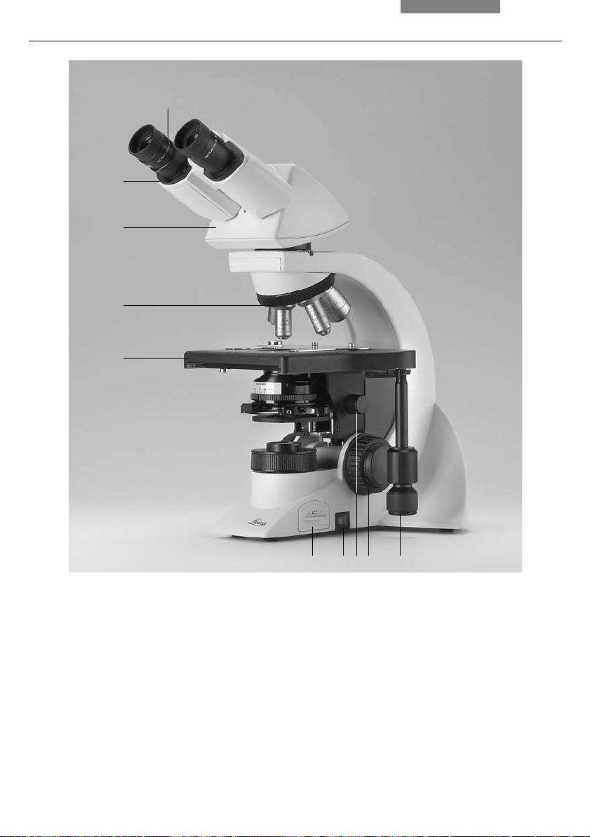
4. Geräteübersicht
1
2
3
4
5
Abb. 2 Rechte Stativseite Leica DM1000
1 Okulare
2 Okularstutzen
3 Tubus
4 Objektivrevolver mit Objektiven
5 Objekttisch mit Präparatehalter
6 Einbaubeleuchtung
7 Ein-/Ausschalter
8 Kondensorhöhenverstellung
9 Grob- und Feinfokussierung
10 Koaxialtrieb zur x-, y-Tischverschiebung
678910
13
5. Auspacken
5. Auspacken
Entnehmen Sie zunächst vorsichtig alle Komponenten dem Transport- und Verpackungsmaterial.
Hinweis:
Das Berühren der Linsenoberfläche der Objektive ist möglichst zu vermeiden. Entstehen dennoch Fingerabdrücke auf den Glasflächen, so
sind diese mit einem weichen Leder- oder
Leinenlappen zu entfernen. Schon geringe Spuren von Fingerschweiß können die Oberflächen
in kurzer Zeit angreifen. Weitere Hinweise im
Kapitel „Pflege des Mikroskops” →
Achtung!
Mikroskop und Peripheriegeräte auf keinen Fall bereits jetzt an die Steckdose anschließen!
S. 54.
Aufstellungsort
Das Arbeiten mit dem Mikroskop sollte in einem
staubfreien Raum erfolgen, der frei von Dämpfen
(Öl, Chemikalien usw.) und extremer Luftfeuchtigkeit ist. Am Arbeitsplatz sollen außerdem große
Temperaturschwankungen, direkt einfallendes
Sonnenlicht und Erschütterungen vermieden
werden. Hierdurch können Messungen bzw.
mikrografische Aufnahmen gestört werden.
Zulässige Umgebungsbedingungen:
Temperatur 15–35°C
Relative Luftfeuchtigkeit max. 80% bis 30°C
Mikroskope in warmen und feucht-warmen
Klimazonen brauchen besondere Pflege, um einer Fungusbildung vorzubeugen.
Weitere Hinweise in den Kapiteln „Pflege des
Mikroskops“ →
S. 54.
Achtung!
14
Elektrische Komponenten müssen mindestens
10 cm von der Wand und von brennbaren
Gegenständen entfernt aufgestellt werden.

Transport
Für den Versand oder Transport des Mikroskops
und seiner Zubehörkomponenten sollte die
Originalverpackung verwendet werden.
Um Beschädigungen durch Erschütterungen zu
vermeiden, sollten vorsorglich folgende Komponenten demontiert und gesondert verpackt
werden:
• Schrauben Sie die Objektive heraus
• Entfernen Sie den Kondensor
• Entfernen Sie den Koaxialtrieb
• Nehmen Sie die Lampenhäuser ab
• Demontieren Sie den Brenner im Lampenhaus
106z
• Entfernen Sie alle beweglichen bzw. losen Teile
5. Auspacken
15

6. Montage
6. Montage des Mikroskops
Die Mikroskopkomponenten werden sinnvollerweise in dieser Reihenfolge montiert:
• Zubehör Objekttisch
• Kondensor
• Fluoreszenzilluminator*
• Zwischensysteme*
• Tubus
• Okulare
• Objektive
• Lampenhäuser mit Lichtquellen*
• Polarisationseinrichtung*
Für die Montage ist nur ein universell verwendbarer Schlüssel notwendig, der im Lieferumfang
enthalten ist. Zur Aufbewahrung des Schlüssels
dient eine Magnetvorrichtung rechts an der Unterseite des Tisches.
Bei Verwendung von Zwischensystemen und
optischem Zubehör kann die Reihenfolge abweichen.
Lesen Sie dazu das Kapitel
„6.9 Optionales Zubehör“ →
6.1 Objekttisch
S. 25.
Koaxialtrieb
Hinweis:
Der Koaxialtrieb kann sowohl rechts- wie auch
linksseitig montiert werden.
• Stecken Sie zunächst den flachen FokusFeintriebknopf auf der Seite auf, an der Sie
den Koaxialtrieb befestigen wollen; der Knopf
wird magnetisch gehalten (4.1); achten Sie
darauf, dass der Knopf einrastet; der andere
Fokusknopf wird entsprechend auf der gegenüberliegenden Seite befestigt
• Lockern Sie die Arretierungsschraube (5.1)
links vorne am Tisch
• Schieben Sie den Tisch so weit wie möglich
nach hinten
• Befestigen Sie den Koaxialtrieb mit der
Schraube (6.1)
• Bringen Sie den Tisch wieder in die Ausgangsposition und ziehen Sie die Arretierungsschraube wieder fest; nach Installation
den Objekthalter ganz nach links drehen und
Trieb weiterdrehen bis man ein Klicken hört
Achtung:
!
Vor der Komplettierung des Objekttisches dürfen
die Objektive noch nicht eingeschraubt werden!
Entfernen Sie die Schraube der Transportsicherung. Diese befindet sich unter der Vorderseite des Tisches.
Präparatehalter
• Setzen Sie den Präparatehalter auf den Tisch
auf und befestigen Sie ihn mit den beiden
Schrauben (3.1)
16
Abb. 3 Objekttisch mit Präparatehalter
1 Befestigungsschrauben für Präparatehalter
1

6. Montage
Fokusschwelle einstellen
Die Fokusschwelle ist werkseitig voreingestellt,
um ein Beschädigen der Objektive zu verhindern. Die Fokusschwelle sollte etwa 0,3 mm höher als die Fokusebene eingestellt sein, damit
Proben unterschiedlicher Dicke fokussiert werden können.
Um die Fokusschwelle nachträglich zu ändern,
gehen sie folgendermaßen vor:
• Senken Sie den Tisch um etwa eine halbe Umdrehung mit dem Grobtrieb
• Lösen Sie die Schraube für die Fokusschwelle
auf der linken Seite des Mikroskops
• Bewegen Sie den Tisch in die gewünschte
Fokusebene (ggf. ca. 0,3 mm höher)
• Ziehen Sie die Schraube wieder fest
Tischfixierung*
Die Tischfixierung wird an der gleichen Stelle
wie die Befestigung des Koaxialtriebs angebracht (im Falle von ErgoTischen kann dies auch
auf der entgegengesetzten Seite des Koaxialtriebs sein).
Die Montage der Tischfixierung ist identisch mit
der Montage des Koaxialtriebs:
• Lockern Sie die Arretierungsschraube (5.1)
links vorne am Tisch und schieben Sie den
Tisch so weit wie möglich nach hinten
• Lockern Sie die Befestigungsschraube für den
Koaxialtrieb (6.1), entfernen Sie den Koaxialtrieb und befestigen Sie die Tischfixierung mit
dieser Schraube
• Lockern Sie die Schraube der Tischfixierung
und bewegen Sie den Tisch nach vorne in die
gewünschte Position
• Ziehen Sie die Arretierungsschraube (5.1)
links vorne am Tisch wieder fest
• Drücken Sie das Zahnrad der Tischfixierung
gegen die Zahnstange und ziehen Sie die
Schraube der Tischfixierung wieder fest
Abb. 5 Unterseite Objekttisch
1 Arretierungsschraube
1
Abb. 4 Fokushandrad
1 Magnethalterung für Fokus-Feintriebknopf
Abb. 6 Montage Koaxialtrieb
1 Befestigungsschraube für Koaxialtrieb
1
1
17

6. Montage
6.2 Kondensor
• Schrauben Sie gegebenenfalls den Kondensorkopf in den Kondensor ein
• Drehen Sie den Kondensorhalter (Abb. 8) mittels der Kondensorhöhenverstellung (9.3)
ganz nach unten
• Drehen Sie die Klemmschraube für den Kondensor (9.2) soweit heraus, dass der Kondensor von vorne eingesetzt werden kann
• Schieben Sie den Kondensor von vorne bis
zum Anschlag in den Kondensorhalter ein; auf
der Unterseite des Kondensors befindet sich
ein Orientierungsstift (7.1), der in die
Führungsnut (8.1) einrasten muss
• Ziehen Sie die Klemmschraube (9.2) für den
Kondensor an, so dass der Kondensor arretiert wird
Abb. 7 Kondensorunterseite (Beispiel CL/PH)
1 Orientierungsstift
2 Zusatzlinse LS
Hinweis:
Vor dem Mikroskopieren muss der Kondensor
zentriert werden.
Köhlersche Beleuchtung S. 28.
→
Abb. 8 Kondensorhalter
1 Führungsnut
1
Abb. 9 Kondensorhalter
1 Kondensorzentrierung
2 Klemmschraube für Kondensor
3 Kondensorhöhenverstellung
18
1
1
3
1
3
2
1
2

6. Montage
6.3 Tubus und Okulare
Hinweis:
Für Fluoreszenzanwendungen muss zuerst der
Fluoreszenzilluminator* montiert werden → S. 21.
Sofern vorhanden muss zuerst der Analysator*
(10.1) ins Stativ eingesteckt werden. Die Orientierungsnut muss dabei in den Orientierungsstift
(10.2) einrasten.
Zur Aufnahme des Analysators kann auch die
Analysatoraufnahme TL* 20 mm bzw. 60 mm zwischen Stativ und Tubus eingesetzt werden.
Optional ist auch ein Zwischentubus-Pol* mit
ein- und ausschaltbarem Analysator und Bertrandlinse verfügbar.
Der Tubus wird direkt oder über Zwischenmodule* am Stativ montiert:
• Drehen Sie die Klemmschraube (11.1) am Stativ etwas heraus
• Setzen Sie den Tubus in die kreisförmige Aufnahme (Ringschwalbe) ein
• Ziehen Sie die Klemmschraube (11.1) wieder
fest.
• Die Okulare werden in die Okularstutzen am
Tubus eingesetzt
6.4 Objektive
Grundsätzlich nur Leica Objektive der Tubuslänge ¥ (unendlich) verwenden! Standardgewindemaß ist M25. Es wird empfohlen, die
Objektive so anzuordnen, dass die Vergrößerung ansteigt, wenn der Objektivrevolver gegen
den Uhrzeigersinn gedreht wird.
!
Achtung:
Zur Montage der Objektive den Tisch möglichst
weit absenken. Nicht besetzte Gewinde im Revolver mit Staub-Schutzkappen verschließen!
Abb. 10 Analysatoreinbau
1 Analysator
2 Orientierungsstift und -nut
3 Klemmschraube
Abb. 11 Befestigen des Tubus
1 Klemmschraube
1
19

6. Montage
6.5 Lichtquelle für die Durchlichtachse
Achtung!
Hinweis:
Das Leica DM1000 LED verfügt über eine eingebaute LED-Beleuchtung. Die Lebensdauer der
LED beträgt ca. 100000 Stunden. Sollte dennoch
ein Wechsel der LED nötig sein, darf dieser nur
vom Technischen Service durchgeführt werden.
Die folgenden Anweisungen in diesem Kapitel
gelten für das Leica DM1000 mit Halogenbeleuchtung.
Achtung!
Achten Sie darauf, dass das Lampenhaus
bzw. das Mikroskop von der Stromversorgung getrennt ist. Netzstecker und Stromversorgung während der Montage vom Netz
trennen.
Es besteht generell bei den Lichtquellen eine
Gefährdung durch Strahlung (Blendung, UVStrahlung, IR-Strahlung). Lampen müssen
daher in geschlossenen Gehäusen betrieben
werden.
Lampenwechsel bei der Einbaubeleuchtung
Die Durchlichtbeleuchtung mit NiedervoltHalogenglühlampe (Abb. 12) ist im Mikroskopfuß
eingebaut und von der rechten Mikroskopseite
zugänglich.
• Ziehen Sie den Einschub (12.2) heraus
Achtung!
Die Glühlampe kann noch heiß sein!
• Ziehen Sie die defekte Glühlampe heraus
Achtung!
Abb. 12 Durchlichtbeleuchtung im
Leica DM1000 Mikroskopfuß
1 Halogenglühlampe
2 Einschub
12
20
Schutzhülle der neuen Lampe erst nach dem
Einsetzen entfernen. Fingerabdrücke unbedingt vermeiden.
• Stecken Sie die neue Lampe mit der Schutzhülle bis gegen den Anschlag gerade in den
Sockel; achten Sie darauf, dass die Lampe gerade sitzt
• Entfernen Sie die Schutzhülle der Lampe
• Stecken Sie den Einschub (12.2) wieder ein

6.6 Komponenten für Fluoreszenzanwendungen*
6.6.1 Fluoreszenzilluminator*
6. Montage
Achtung!
Der Fluoreszenzilluminator wird vor dem Tubus
montiert. Die Befestigung erfolgt über die seitliche Klemmschraube (13.1).
6.6.2 Lampenhaus 106z*
Achtung!
Es besteht generell bei den Lichtquellen eine
Gefährdung durch Strahlung (Blendung, UVStrahlung, IR-Strahlung). Lampen müssen
daher in geschlossenen Gehäusen betrieben
werden.
Achten Sie darauf, dass das Lampenhaus
von der Stromversorgung getrennt ist. Netzstecker und Stromversorgung während der
Montage vom Netz trennen.
Bei Montagearbeiten an Xe-Brennern immer
mitgelieferte Schutzhandschuhe und Gesichtsschutz (Abb. 14) tragen (Explosionsgefahr).
Beachten Sie unbedingt die Gebrauchsanweisung und Sicherheitshinweise der
Lampenhersteller!
Vor dem Wechseln von Lampen diese mindestens 30 min abkühlen lassen!
Einsetzen der Gasentladungslampen* (Hg und
Xe) in das Lampenhaus 106z
Hg- und Xe-Lampen werden mit separaten Vorschaltgeräten betrieben.
Bitte unbedingt die gesonderte Anleitung dieser
Vorschaltgeräte beachten.
Abb. 13 Montage Fluoreszenzilluminator
1 Klemmschraube
1
Glasteile des Brenners nie mit bloßen Händen anfassen.
Nie in den direkten Strahlengang blicken
(Blendgefahr).
Das Lampenhaus 106z wird mit verschiedenen
Gasentladungslampen verwendet.
Abb. 14
Schutzhandschuhe und Gesichtsschutz
21
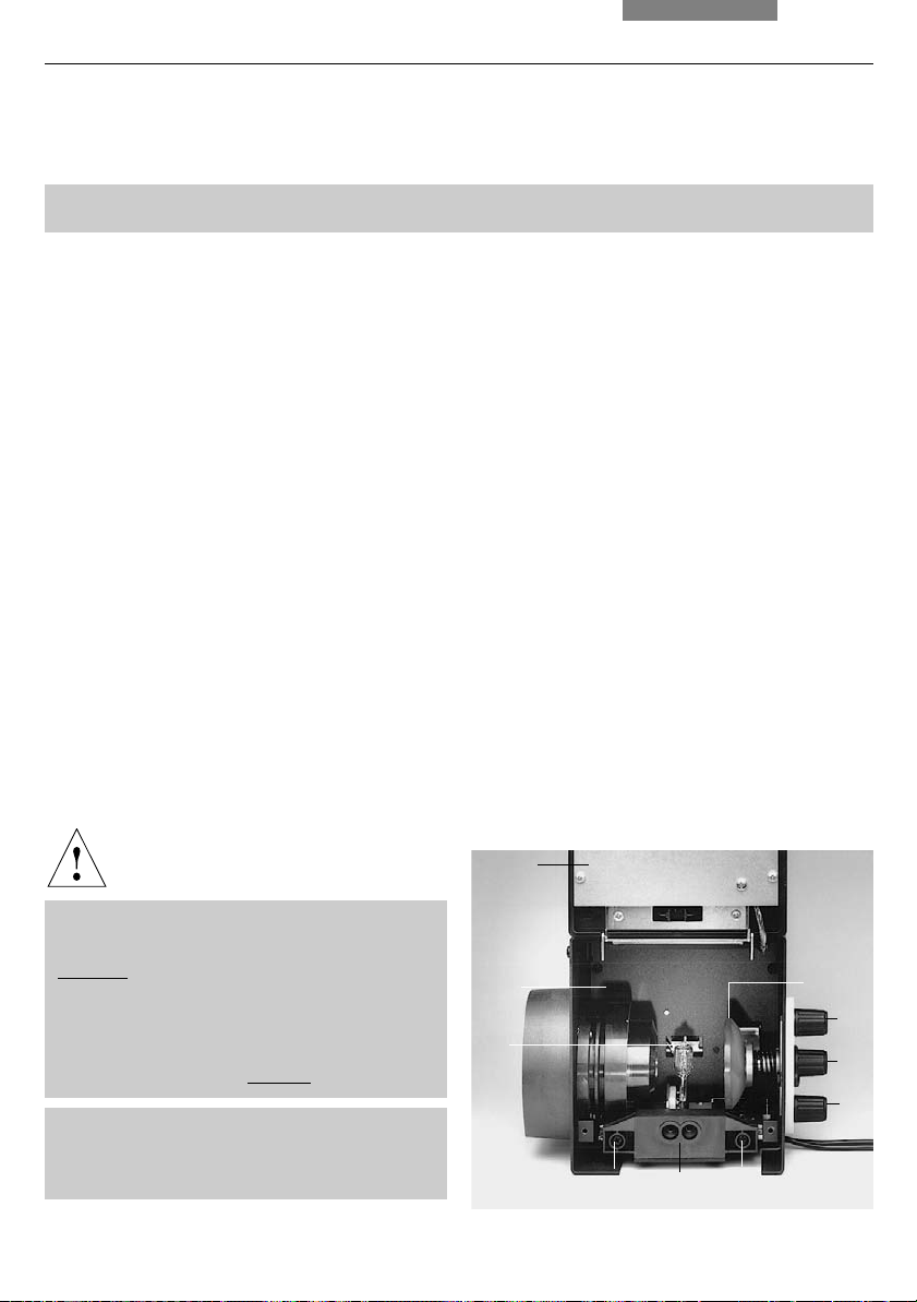
6. Montage
Folgende Gasentladungslampen sind einsetzbar
und erfordern unterschiedliche Stromversorgungsgeräte und Lampenfassungen (Abb. 16):
Typ Typische Lebensdauer
Hg-Höchstdrucklampe 50 W (Wechselstrom) 100 h
Hg-Höchstdrucklampe 100 W (Gleichstrom) 200 h
Hg-Höchstdrucklampe 100 W, Typ 103 W/2 (Gleichstrom) 300 h
Xe-Hochdrucklampe 75 W (Gleichstrom) 400 h
+) Bitte beachten Sie die Datenblätter der Lampenhersteller.
• Zum Öffnen des Lampenhauses 106z lösen Sie
die Befestigungsschrauben (15.8) am Verschlussdeckel
• Entfernen Sie die Transportsicherung (roter
Kunststoffstab anstelle des Brenners) der
Lampenfassung; lösen Sie dazu die obere
Klemmung (16.1); ziehen Sie das Kühlelement
(16.3) nach oben und drehen Sie es zur Seite;
lösen Sie die untere Klemmung (16.2) und entfernen Sie die Transportsicherung
• Setzen Sie den Brenner in umgekehrter Reihenfolge ein
Abb. 15 Lampenhaus 106z (seitlich, geöffnet)
1 Deckel (hochgestellt)
2 Kollektor
3 Gasentladungslampe in Fassung
4 Reflektor (Spiegel)
5, 6, 7 Justierschrauben x-y Reflektor
8 Befestigungsschrauben für Lampenfassung
9 Buchse für Kontaktstecker
+)
Achtung!
Hg 50-Brenner:
Die Beschriftung muss nach dem Einbau
aufrecht stehen.
Ein evtl. vorhandener Glas-Abschmelznippel
(16a.4) wird durch Drehen des Brenners so
ausgerichtet, dass der Nippel später nicht im
Strahlengang, sondern
seitlich orientiert ist.
Xe 75-Brenner:
Schutzhülle des Brenners (16b.5) nach dem
Einbau entfernen.
22
1
2
4
5
3
6
7
898

6. Montage
• Setzen Sie die Lampenfassung wieder ein und
ziehen Sie die Befestigungsschrauben (15.8)
wieder an
• Schließen Sie das Lampenhaus und ziehen Sie
die Befestigungsschrauben wieder an
• Setzen Sie das Lampenhaus an die AuflichtLampenhausaufnahme (17.1) an und befestigen Sie es mit der seitlichen Klemmschraube
• Schließen Sie das Lampenhaus am Vorschaltgerät an
Abb. 16 a-c Lampenfassungen für Gasentladungslampen
1 Obere Klemmung
2 Untere Klemmung
3 Kühlelement
4 Abschmelznippel des Hg 50-Brenners
5 Schutzhülle des Xe 75-Brenners
Abb. 17 Ansetzen des Lampenhaus 106z
1 Lampenhausaufnahme
Hg 50
1
4
1
a
3
2
Xe 75
b
Hg 100
3
1
1
c
3
5
2
2
23
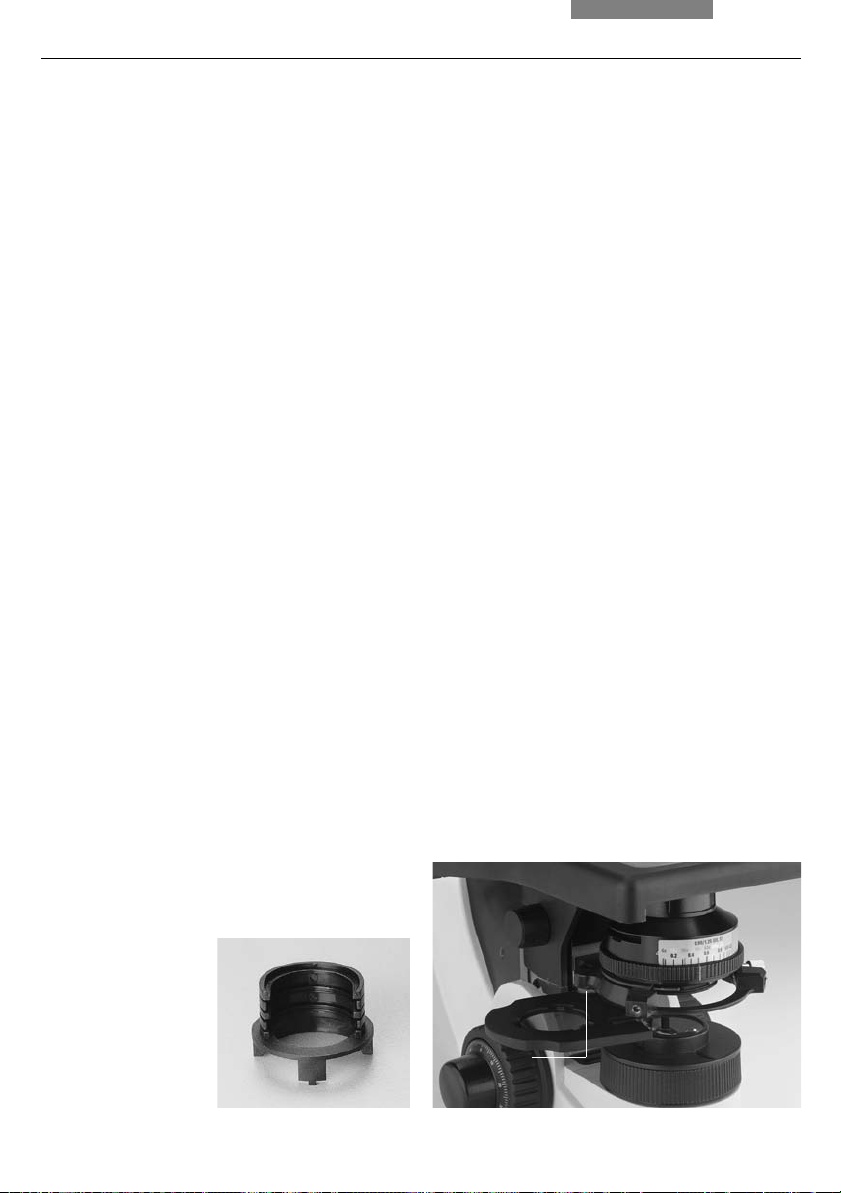
6. Montage
6.7 Analysator und Polarisator*
Analysator
Wurde der Analysator vor der Tubusmontage in
die Tubusaufnahme eingesteckt (→ S. 19), ist
kein weiterer Montageschritt notwendig.
Bei Verwendung des Zwischentubus-Pol* bzw.
der Analysatoraufnahme TL*:
• Entfernen Sie die Steckkappe auf der linken
Seite
• Schieben Sie den Analysator bis zur Rastung
in die Aufnahme
Polarisator
• Drehen Sie den Kondensor bis zum oberen
Anschlag hoch
• Entfernen Sie gegebenenfalls das Filtermagazin DLF auf dem Stativfuß
• Stecken Sie stattdessen den Polarisatorhalter
(Abb. 18) auf
Alternativ:
• Befestigen Sie den Polarisatorhalter mit der
linken Klemmschraube (19.1) an der Unterseite des Kondensorhalters; entfernen Sie
gegebenenfalls den Flipout-Blue-Filter
• Stecken Sie den Polarisator mit der beschrifteten Seite nach oben in die untere Öffnung
6.8 Lambda-Plattenkompensator*
• Drehen Sie den Kondensor bis zum oberen
Anschlag hoch
• Entfernen Sie gegebenenfalls das Filtermagazin DLF auf dem Stativfuß
• Stecken Sie den Lambda-Plattenkompensator
auf den Mikroskopfuß auf
• Stecken Sie den Polarisator mit der beschrifteten Seite nach oben in die untere Öffnung
Abb. 18 Filterhalter*
mit zwei Positionen
24
Abb. 19 Montage des Polarisatorhalters*
1 Klemmschraube
1

6. Montage
6.9 Optionales Zubehör
Kamera*
Über einen Adapter kann eine Kamera kann angeschlossen werden.
• Setzen Sie den Adapter auf den oberen Abgang des Tubus auf und befestigen Sie ihn mit
der seitlichen Klemmschraube
• Schrauben Sie die Kamera auf
Hinweis:
Bei der Wahl des Adapters sind die Größe des
Kamera-Chips und das Wechselsystem (c-mount,
B-mount, usw.) zu beachten (siehe Tabelle).
Berechnung der Vergrößerung auf dem Monitor
Die Vergrößerung V
auf dem Monitor kann
TV
nach folgender Formel berechnet werden oder
mittels eines Objektmikrometers und eines cmMaßstabs gemessen werden.
V
= Objektivvergrößerung x
TV
Faktor-Vergrößerungswechsler* x
Vergrößerung TV-Adapter* x
Bildschirmdurchmesser
Chipdurchm. der Kamera
Aufgenommene Bilddiagonale in mm bei
1-Zoll- 2/3-Zoll- 1/2-Zoll- 1/3-ZollKamera Kamera Kamera Kamera
Ohne variable Vergrößerung, nur für 1-Chip-Kameras:
c-mount-Adapter 1 x HC 16 11 8 6
c-mount-Adapter 0,70 x HC - 15,7 11,4 7,8
c-mount-Adapter 0,55 x HC - - 14,5 10,9
c-mount-Adapter 0,35 x HC - - - 17,1
Mit variabler Vergrößerung (Vario TV-Adapter) für 1-3 Chip-Kameras:
c-mount, 0,32-1,6 x HC - - 19
+)
-5 18-3,8
B-mount (ENG), 0,5-2,4 x HC (1/2-Zoll) - - 16-3,3 -
+)
erst ab Vario Faktor 0,42 x!
Ohne variable Vergrößerung, für 1-3 Chip-Kameras:
c-mount-Adapter 1 x - - 16 12
B-mount-Adapter 1 x - - 16 12
B-mount-Adapter 1.25 x - 17,5 - F-mount-Adapter 1 x - - 16 12
F-mount-Adapter 1,25 x - 17,5 - Dazu jeweils erforderlich: TV-Optik 0,5 x HC
25
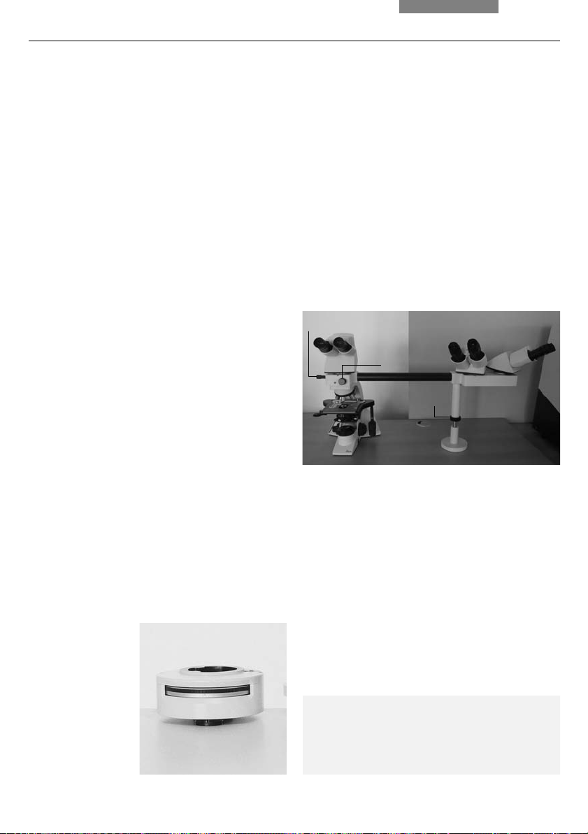
6. Montage
Ergomodul*
Zur Erhöhung des Tubuseinblicks kann zwischen
Tubus und Tubusaufnahme das Ergomodul 30 mm
bzw. 60 mm eingesetzt werden.
Die Befestigung erfolgt durch die seitliche
Klemmschraube.
Montage Tubus auf 60 mm Ergomodul: Der Tubus
muss um 90° gedreht aufgesetzt werden, anschließend Tubus in Normalposition drehen und
Schraube festziehen.
Ergolift*
Für das Stativ steht ein Stativuntersatz zur Verfügung, der in der Höhe und Neigung über Stellräder verstellt werden kann, um eine optimale
Arbeitsposition zu erhalten.
Vergrößerungswechsler*
Optional kann ein Vergrößerungswechsler
(Abb. 20) eingesetzt werden, der manuell bedient wird. An einem Rändelrad können die folgenden Vergrößerungsfaktoren eingestellt werden:
1x; 1,5x; 2x
Diskussionseinrichtungen*
Diskussionseinrichtungen mit beleuchtetem Zeiger stehen für 2, 3, 4, 5 bzw. 10 Beobachter zur
Verfügung (andere Konfigurationen auf Anfrage).
Die Abstützung (21.3) muss exakt gerade gestellt
werden.
Der einblendbare Pfeil kann in x- und y-Richtung
verstellt werden.
Abb. 21 Diskussionseinrichtung
1 Bewegung des Leuchtzeigers in x- und y-Richtung
2 Helligkeitsregelung
3 Verstellung der Stütze
Die externe Stromversorgung (Leuchtzeiger) ist nicht abgebildet.
1
2
3
Zeicheneinrichtung*
Abb. 20 Vergrößerungs-
wechsler
26
Die Zeicheneinrichtung L3/20 (Abb. 22) ermöglicht die Einspiegelung größerer Objekte neben
dem Mikroskop in das mikroskopische Bild. Damit lassen sich u.a. sehr leicht Zeichnungen des
Präparates durch Nachfahren der Objektkonturen erstellen oder Skalen einblenden.
Abb. 22 Zeicheneinrichtung
1 Verschlussklappe
1

6. Montage
6.10 Einsetzen der Akkus (nur bei DM1000 LED)*
Optional kann das Mikroskop mit Akkus betrieben werden. Beim Anschluss des Mikroskops an
die Stromversorgung werden die Akkus automatisch geladen. Die Betriebsdauer im Akkubetrieb
beträgt ca. 6 - 8 Stunden.
• Das Akkufach befindet sich an der Stativunterseite (23a.1); entfernen Sie die Abdeckung des Faches
• Legen Sie die Akkus (Bestellnummer → S. 56)
wie auf dem Boden des Faches angegeben
ein (Abb. 23b) und schließen Sie den Deckel
wieder
Abb. 23a Stativunterseite (DM1000 LED)
1 Deckel des Akkufachs
6.11 Anschluss an die Stromversorgung
• Nach Abschluss der Montagearbeiten wird
das Mikroskop mit dem mitgelieferten Netzkabel an die Spannungsversorgung angeschlossen (Abb. 23c)
• Gegebenenfalls auch das Lampenhaus oder
das externe Vorschaltgerät an die Stromversorgung anschließen
Abb. 23c Stativrückseite (DM1000)/Typenschild
1 Anschluss Spannungsversorgung
1
1
Abb. 23b Stativunterseite (DM1000 LED)
1 Akkufach geöffnet
1
Abb. 23d Stativrückseite (DM1000 LED)/Typenschild
1 Anschluss Netzteil
1
27
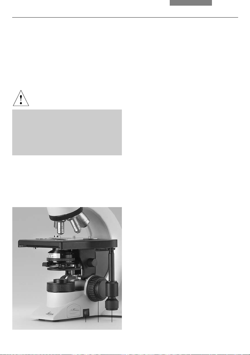
7. Inbetriebnahme
7. Inbetriebnahme
7.1 Einschalten
• Schalten Sie das Mikroskop am Ein-/Ausschalter (24.1) ein
Achtung:
Nach dem Einschalten der Gasentladungslampe* muss der Brenner sofort justiert werden. Schalten Sie deshalb das Vorschaltgerät* noch nicht ein. Arbeiten Sie zunächst
im Durchlicht, um die Bedienelemente des
Mikroskops kennenzulernen.
Abb. 24
1 Ein-/Ausschalter
2 Fokushandrad
3 Tischpositionierung
7.2 Köhlersche Beleuchtung*
Der Kondensor ist bereits werkseitig zentriert.
Bedingt durch den Aus- und Wiedereinbau des
Kondensors kann jedoch in einigen Fällen eine
Nachzentrierung des Kondensors nötig sein.
Überprüfen Sie deshalb die Kondensorzentrierung.
Die folgenden Schritte werden für die Durchlicht-Hellfeldbeleuchtung erklärt.
• Schalten Sie ggf. die Position BF der
Kondensorscheibe* ein
• Ziehen Sie ggf. den Lichtringschieber* aus
dem Kondensor heraus
• Schwenken Sie ein Objektiv mit mittlerer Vergrößerung (10x-20x) ein;
für Kondensoren mit schwenkbarem
Kondensorkopf:
Schwenken Sie den Kondensorkopf ein
(Der Kondensorkopf wird für Objektive <10x
ausgeschwenkt.)
28
• Legen Sie nun ein Präparat in den Präparatehalter des Tisches ein
• Fokussieren Sie auf das Präparat mit dem
Fokushandrad (24.2)
• Stellen Sie die Lichtintensität am Helligkeitsregler (25.2) ein
• Schließen Sie die Leuchtfeldblende (25.3) bis
der Rand der Blende in der Präparateebene
erscheint (26a)
21 3
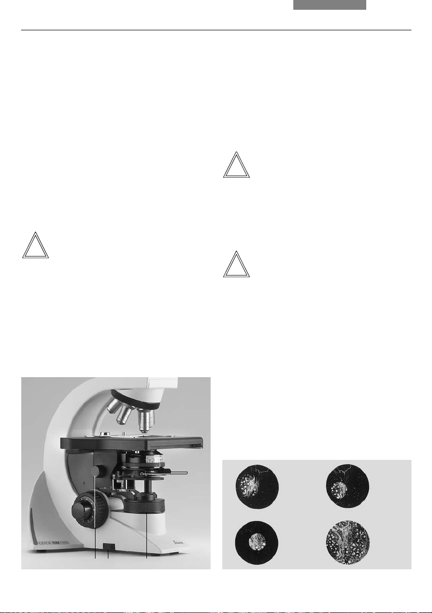
7. Inbetriebnahme
• Mit der Kondensorhöhenverstellung (25.1)
verstellen Sie den Kondensor bis der Rand der
Leuchtfeldblende scharf abgebildet ist (26b)
• Liegt das Bild nicht in der Sehfeldmitte (26c),
muss der Kondensor mit Hilfe der beiden
Zentrierschrauben (25.4) in die Mitte des Sehfeldes bewegt werden; der dafür notwendige
Schlüssel ist magnetisch an der Unterseite
des Tisches befestigt
• Öffnen Sie die Leuchtfeldblende so weit, dass
sie gerade aus dem Sehfeld verschwindet
(26d)
Achtung:
Die Kondensorhöheneinstellung ist abhängig
von der Präparatdicke und muss ggf. für unterschiedliche Präparate neu eingestellt werden.
Abb. 25
1 Kondensorhöhenverstellung
2 Helligkeitseinstellung
3 Leuchtfeldblende
4 Kondensorzentrierung
7.3 Phasenkontrastringe überprüfen
Wenn Ihr Mikroskop für die Verwendung von
Phasenkontrast ausgerüstet ist, wurde die Kondensorscheibe* bereits mit den zu den Objektiven passenden Lichtringen bestückt.
Die Lichtringe sind bereits werkseitig zentriert.
Die Zentrierung sollte jedoch noch einmal überprüft werden.
Hinweis:
Bei Kondensoren ohne Kondensorscheibe wird
ein Lichtringschieber verwendet, der seitlich in
den Kondensor eingeschoben wird. Hierbei entfällt die Zentrierung.
Hinweis:
Beim Einschwenken eines für Phasenkontrast
geeigneten Objektivs muss der entsprechende
Lichtring eingestellt werden.
Die Objektivgravur (z.B. PH 1) gibt den korrespondierenden Lichtring (z.B. 1) an.
Abb. 26 Köhlersche Beleuchtung
a Leuchtfeldblende nicht fokussiert, nicht zentriert,
b Leuchtfeldblende fokussiert, jedoch nicht zentriert,
c Leuchtfeldblende fokussiert und zentriert,
Durchmesser jedoch zu klein,
d Leuchtfelddurchmesser = Sehfelddurchmesser
(Köhlersche Beleuchtung)
12 3
4
a
b
cd
29

7. Inbetriebnahme
• Setzen Sie anstelle eines Okulars das Einstellfernrohr (Abb. 27) in den Beobachtungstubus
ein
• Schwenken Sie das Phasenkontrastobjektiv
mit der kleinsten Vergrößerung ein
• Fokussieren Sie das Präparat mit dem Fokushandrad
• Stellen Sie die Ringstruktur (29a) scharf, indem Sie den Klemmring (27.2) etwas lockern
und die Augenlinse (27.1) verschieben
• Ziehen Sie den Klemmring wieder an
• Wählen Sie die korrespondierende Ringblende (Lichtring) im Kondensor
• Sind Lichtring und Phasenring nicht, wie in
Abb. 29c gezeigt, deckungsgleich, muss der
Lichtring zentriert werden
• Stecken Sie an der Rückseite des Kondensors
die Zentrierschlüssel durch die dafür vorgesehenen Öffnungen (28.1)
Abb. 27 Einstellfernrohr
1 Verstellbare Augenlinse
2 Klemmring zur Fixierung der Fokuslage
• Drehen Sie die Zentrierschlüssel, bis der
dunkle Ring (Phasenring im Objektiv) deckungsgleich mit dem geringfügig schmaleren
hellen Ring (Lichtring im Kondensor) ist (29c)
• Wiederholen Sie den Vorgang für alle weiteren Lichtringe und Objektive
• Nach dem Zentrieren die Zentrierschlüssel
evtl. wieder herausnehmen
Abb. 28 Zentrierung Lichtringe (z.B: Kondensor UCL/P)
1 Zentrierschlüssel
11
Abb. 29 Zentriervorgang Phasenkontrast
PH=Phasenkontrastring, LR=Lichtring
a Kondensor in Position Hellfeld (BF)
b Kondensor in Position Phasenkontrast (PH),
Lichtring LR nicht zentriert
c Lichtring und Phasenring zentriert
30
1
ab c
2
PH LR
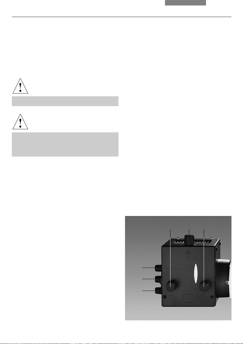
7. Inbetriebnahme
7.4 Justieren der Lichtquellen
Eine Zentrierung ist nur bei Verwendung des
Lampenhauses 106z* notwendig.
• Bei Verwendung eines Vorschaltgerätes wird
dieses zuerst eingeschaltet
Achtung!
Nie in den direkten Strahlengang blicken!
Achtung!
Es besteht generell bei den Lichtquellen eine
Gefährdung durch Strahlung (Blendung, UVStrahlung, IR-Strahlung).
Beim Lampenhaus 106z werden direktes Bild
des Lichtbogens (bei Gasentladungslampen)
und dessen Spiegelbild getrennt fokussiert und
zueinander justiert.
• Bringen Sie das Filtersystem* bzw. den Reflektor* in den Strahlengang
• Legen Sie ein Blatt Papier auf den Objekttisch
und fokussieren Sie die Oberfläche mit einem
Trockenobjektiv schwacher bis mittlerer Vergrößerung
• Stellen Sie die Leuchtfeld- und Aperturblende
in eine mittlere Position
• Machen Sie mit einem Stift eine Markierung
auf das Papier und verschieben Sie die Markierung in die Mitte des beleuchteten Feldes
• Entfernen Sie das Objektiv oder schwenken
Sie eine nicht besetzte Position ein
Die Lichtquelle wird jetzt auf dem Papier abgebildet. Unter Beobachtung der Lichtquelle wird
die Lampe wie folgt justiert.
Abb. 30 Lampenhaus 106z
1 Höhenjustierung der Lampe
2,4 Höhen- und Seitenjustierung des Spiegelbildes
3 Fokussierung des Reflektors
5 Seitenjustierung der Lampe
6 Kollektor (Fokussierung des Lampenbildes)
• Öffnen Sie ggf. den Shutter und entfernen Sie
ggf. Streuscheiben* aus dem Strahlengang
516
2
3
4
31

7. Inbetriebnahme
Zentrieren der Quecksilberlampe Hg 50 W*
• Auf dem Papier sehen Sie das direkte Bild des
Lichtbogens und das Spiegelbild, die in der
Regel gegeneinander verschoben sind
• Stellen Sie das direkte Bild mit dem Kollektor
scharf (30.6)
• Schwenken Sie das Spiegelbild des Lichtbogens mit den Justierknöpfen an der Rückseite
des Lampenhauses (30.2, 30.4) zur Seite oder
ganz aus dem Strahlengang; es bleibt das fokussierte Bild des Lichtbogens sichtbar
(Abb. 31)
• Platzieren Sie das direkte Bild des Lichtbogens mit den Justierknöpfen (30.1) und (30.5)
rechts oder links an einer gedachten Mittellinie der Zentrierfläche (Abb. 32)
• Schwenken Sie nun das Spiegelbild des Lichtbogens mit den Justierknöpfen (30.2) und
(30.4) wieder ein und stellen Sie es mit Hilfe
des Reflektors scharf (30.3)
Abb. 31 Direktes Bild des Lichtbogens fokussiert, aber
dezentriert (in Wirklichkeit ist das Bild unschärfer)
Abb. 32 Direktes Bild des Lichtbogens in Sollposition
(in Wirklichkeit ist das Bild unschärfer)
• Richten Sie das Spiegelbild symmetrisch zu
dem direkten Bild aus (Abb. 33); benutzen Sie
dazu wieder die Justierknöpfe (30.2) und (30.4)
• Defokussieren Sie das Bild nun über den Kollektor mit dem Kollektorknopf (30.6) bis das
Bild des Lichtbogens und das Spiegelbild
nicht mehr zu erkennen sind und das Bild homogen ausgeleuchtet ist
32
Abb. 33 Direktes Bild des Lichtbogens und Spiegelbild in
Sollposition (in Wirklichkeit ist das Bild unschärfer)

7. Inbetriebnahme
Zentrieren der Quecksilberlampen Hg 100 W*
und des Xe-Brenners 75 W*
• Auf dem Papier sehen Sie das direkte Bild des
Lichtbogens und das Spiegelbild, die in der
Regel gegeneinander verschoben sind
• Stellen Sie das direkte Bild mit dem Kollektor
scharf (30.6)
• Schwenken Sie das Spiegelbild des Lichtbogens mit den Justierknöpfen an der Rückseite
des Lampenhauses (30.2, 30.4) zur Seite oder
ganz aus dem Strahlengang; es bleibt das
fokussierte Bild des Lichtbogens sichtbar
(Abb. 34)
• Platzieren Sie das direkte Bild des Lichtbogens mit den Justierknöpfen (30.1) und (30.5)
in der Mitte der Zentrierfläche, wobei die helle Spitze des Lichtbogens, der Kathodenbrennfleck, etwas außerhalb der Mitte liegen
soll (Abb. 35)
• Schwenken Sie nun das Spiegelbild des Lichtbogens mit den Justierknöpfen (30.2) und
(30.4) wieder ein und stellen Sie es mit Hilfe
des Reflektors scharf (30.3)
Abb. 34 Direktes Bild des Lichtbogens fokussiert, aber
dezentriert (in Wirklichkeit ist das Bild unschärfer)
Abb. 35 Direktes Bild des Lichtbogens in Sollposition
(in Wirklichkeit ist das Bild unschärfer)
• Richten Sie das Spiegelbild symmetrisch zu
dem direkten Bild aus (Abb. 36); benutzen Sie
dazu wieder die Justierknöpfe (30.2) und (30.4);
die V-förmige Abstrahlung der Lichtbögen von
direktem Bild und Spiegelbild können überlagert werden
Achtung!
Die hellen Spitzen der Lichtbögen, die
Kathodenbrennflecke, dürfen jedoch keinesfalls übereinander projiziert werden, weil
dann durch Überhitzung Explosionsgefahr
besteht.
Abb. 36 Direktes Bild des Lichtbogens und Spiegelbild in
Sollposition (in Wirklichkeit ist das Bild unschärfer)
33

7. Inbetriebnahme
Achtung!
Bei älteren Lampen ist die Struktur des
Lichtbogens nicht mehr klar erkennbar. Das
Bild ähnelt dann mehr dem einer Hg 50-Lampe. Bild und Spiegelbild können daher nicht
mehr exakt übereinander plaziert werden.
Bringen Sie in diesem Fall beide Bilder zur
Deckung.
• Defokussieren Sie das Bild nun über den Kollektor mittels des Knopfes (30.6) bis das Bild
des Lichtbogens und das Spiegelbild nicht
mehr zu erkennen sind und das Bild homogen
ausgeleuchtet ist
34

8. Bedienung
8. Bedienung
8.1 Einschalten
Bei Verwendung einer Gasentladungslampe*
muss das Vorschaltgerät* zunächst separat eingeschaltet werden.
Schalten Sie das Mikroskop am Ein/Aus-Schalter (37.1) ein.
8.2 Tische und Objektverschiebung
Verlängern des Koaxialtriebs (teleskopierbar)*
Zum Verlängern ziehen Sie den unteren Griff
(38b.1) nach unten. Dann führen Sie den oberen
Griff (38b.2) entsprechend nach.
Abb. 37
1 Ein-/Ausschalter
2 Grobfokussierung
3 Feinfokussierung
4 Tischpositionierung
5 Arretierungsschraube des Tisches
6 Befestigungsschraube des Koaxialtriebs
Einstellen der Gängigkeit (Drehmoment)*
Das Drehmoment kann individuell durch zwei
Rändel (38b.2, 38b.4) für X und Y angepasst werden.
Korrektur des Verfahrbereichs des Tisches
Falls nach längerem Arbeiten mit dem Mikroskop
sich der Verfahrbereich des Tisches in X-Richtung einmal verringern sollte, kann dies wie folgt
korrigiert werden:
Fahren Sie mit dem Koaxialtrieb den Objektführer soweit wie möglich nach links und drücken Sie eine der Schrauben, die den Objektführer halten, von Hand noch weiter nach links
bis zum Anschlag. Anschließend den Objektführer ganz nach rechts fahren. Auch hier genügt ein leichter Druck auf eine der Schrauben,
diesmal nach rechts zum Anschlag, um den vollen Verfahrbereich des Tisches wiederherzustellen.
Abb. 38a Standard-Koaxialtrieb, b Koaxialtrieb mit Höhen-
und Drehmomenteinstellung*
1 Objektverschiebung (Y-Richtung)
6
2 Einstellen der Gängigkeit (X-Richtung)
3 Objektverschiebung (X-Richtung)
4 Einstellen der Gängigkeit (Y-Richtung)
a
b
5
4
3
3
2
2
3
1 4
1
1
35

8. Bedienung
Rechts-/Linksbedienung
Der Koaxialtrieb lässt sich sowohl rechts wie
auch links am Tisch befestigen. (Siehe auch
Montage S. 16f). Zum Wechseln der Seite gehen
Sie folgendermaßen vor:
• Lockern Sie die Arretierungsschraube (37.5)
links unten am Tisch; den Schlüssel dafür finden Sie rechts an der Unterseite des Tisches
!
Achtung!
Der Kondensor muss unbedingt abgesenkt
werden!
• Schieben Sie dann den Tisch ganz nach
hinten
• Lösen Sie die Schraube (37.6) am Koaxialtrieb
und ziehen Sie ihn heraus
• Stecken Sie den flachen Fokus-Feintriebknopf
(37.3) auf der Seite auf, an der Sie den
Koaxialtrieb befestigen wollen; der Knopf wird
magnetisch gehalten; achten Sie darauf, dass
der Knopf einrastet; der andere Fokusknopf
wird entsprechend auf der anderen Stativseite befestigt
• Befestigen Sie den Koaxialtrieb auf der anderen Tischseite, indem Sie die entsprechende
Schraube wieder festziehen
8.3 Fokussierung
Grob- und Feinfokussierung
Auf beiden Stativseiten befinden sich Fokushandräder zur Grob- und Feinfokussierung
(Abb. 37 und 39).
Die spezielle Form des flachen Fokus-Feintriebknopfs (37.3) ermöglicht es, gleichzeitg den
Koaxialtrieb mit der Hand zu umfassen und mit
einem Finger den Feintrieb zu bedienen. Deshalb sollte der flache Knopf auf der entsprechenden Seite aufgesteckt werden. Siehe
Rechts-/Linksbedienung des Tisches.
Höhenverstellung der Fokusknöpfe
• Defokussieren Sie das mikroskopische Bild,
indem Sie den Tisch mit einer Umdrehung des
Grob-Fokushandrads (37.2, 39.1) nach unten
verstellen
• Umfassen Sie den rechten und linken Fokusknopf gleichzeitig und und schieben Sie die
Knöpfe mit leichtem Druck nach oben bzw.
nach unten in die gewünschte Position
• Fokussieren Sie das Bild wieder
Abb. 39 Fokusknopf mit Skalierung
1 Grobfokussierung
2 Feinfokussierung
• Bringen Sie den Tisch wieder in die Ausgangsposition und ziehen Sie die Arretierungsschraube wieder fest; nach Installation
den Objekthalter ganz nach links drehen und
Trieb weiterdrehen bis man ein Klicken hört
• Stellen Sie den Kondensor wieder ein
36
1
2

8. Bedienung
8.4 Tuben
Hinweis:
Verschließen Sie nicht benutzte Tubusausgänge, da sonst Streulicht die Beobachtung
stören kann.
Augenabstand einstellen
Stellen Sie den Augenabstand der Okularrohre
so ein, dass ein deckungsgleiches Gesamtbild
wahrgenommen wird (Abb. 40).
Einblickwinkel einstellen
• Bei den Ergonomietuben* HC LVB 0/4/4 und
HC -/0/4 kann der Einblickwinkel durch Kippen
des Binokulareinblicks eingestellt werden
Ergotubus (lang, schwenkbar): 0° - 35°
Ergotubus (kurz, schwenkbar): 7,5° - 32,5°
• Bei den Ergotuben* AET22 und EDT22 kann
der Einblickwinkel durch Kippen des Binokulareinblicks im Bereich von 5° - 32° eingestellt werden (Abb. 41)
Okularauszug an Armlänge anpassen
• Am Tubus AET22 können die Okulare bis zu
30 mm ausgezogen werden (Abb. 41)
Strahlenteilung bei Fototuben*
Tubus EDT22:
Die Lichtaufteilung zwischen Beobachtungsund Dokumentationsausgang ist fest eingestellt
(50:50).
Tubus BDT P 25:
Die Lichtaufteilung wird manuell durch Herausziehen einer Schaltstange eingestellt.
Schaltstange Beobachtung Foto
VIS 100% 0%
50/50 50% 50%
PHOTO 0% 100%
Abb. 40 Tubuseinstellung
↔ Einstellung des persönlichen Augenabstandes
↔
Abb. 41 Individuelle Einstellungen am Tubus AET22*
37
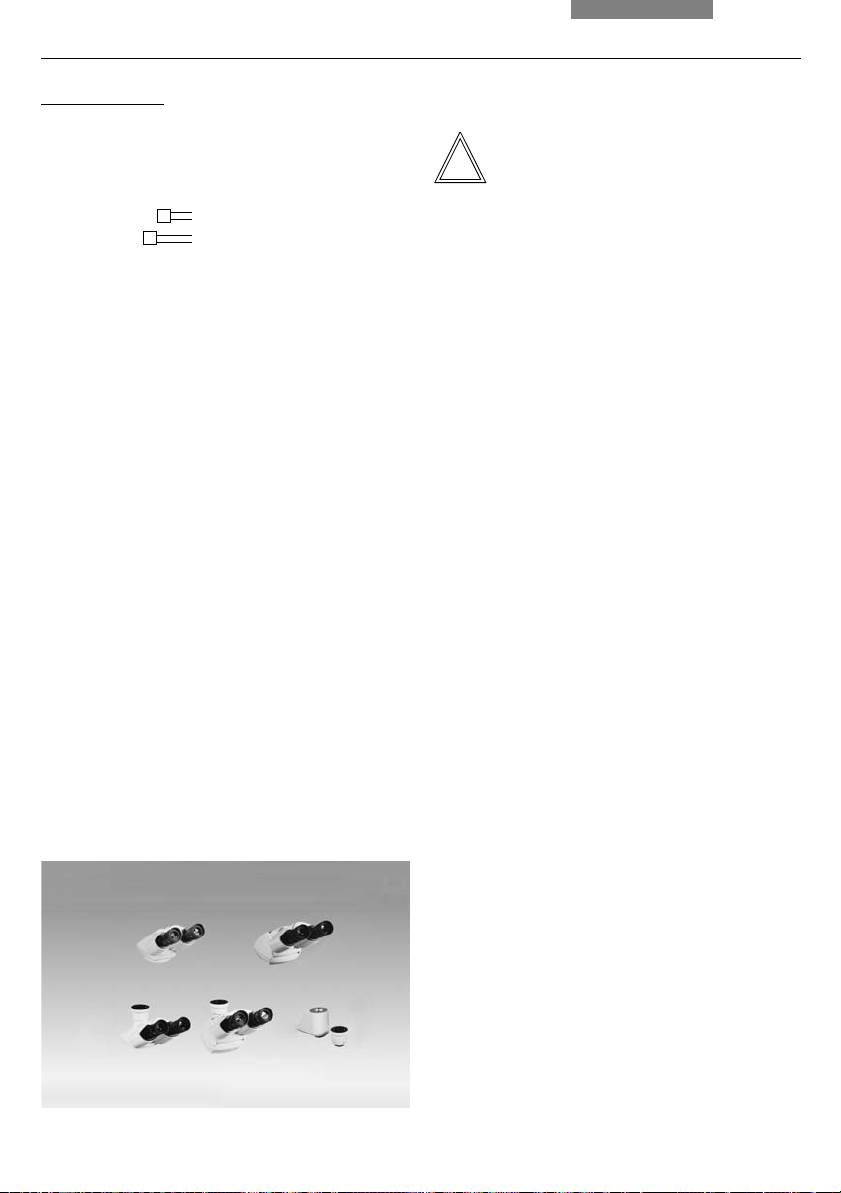
8. Bedienung
Tubus HC L 2TU:
Die Lichtaufteilung wird manuell durch Herausziehen einer Schaltstange eingestellt.
Schaltstange Beobachtung Foto
VIS 100% 0%
PHOTO 0% 100%
Abb. 42 Tubusprogramm HC L (Auszug)
1 Binokularer Beobachtungstubus HC LB 0/3/4
2 Ergonomietubus HC LVB 0/4/4, binokular,
Einblickwinkel 0-35°
zusätzlich Ergotubus (kurz) HC -/0/4,
schwenkbar 7,5°-32,5°
3 Trinokularer Tubus H L1T 4/5/7, mit festem Strahlenteiler
(50% / 50%)
4 HC L1VT 0/4/4 wie 3,
jedoch mit verstellbarem Einblickwinkel 0-35°
5 Fotostutzen, mit 2 Ausgängen (50% / 50%)
6 Foto-TV-Ausgang
8.5 Okulare
Hinweis:
Der Blendschutz der Okulare muss beim Mikroskopieren mit Brille abgenommen bzw. zurückgestülpt werden.
Brillen mit Mehrbereichgläsern (Bifocal- und
Gleitsichtgläser) müssen beim Mikroskopieren
abgesetzt werden.
Wählen Sie bei den schaltbaren Tuben mit Dokumentationsausgang die Stellung 100% VIS.
Okulare mit eingelegter Strichplatte*
• Stellen Sie die Strichplatte durch Verstellen
der Augenlinse im Okular scharf ein
• Fokussieren Sie das Objekt durch dieses Oku-
lar
• Schließen Sie dann das Auge und fokussie-
ren Sie das Objekt jetzt nur durch Verstellen
des zweiten Okulars
Korrektur bei Fehlsichtigkeit
• Blicken Sie mit dem rechten Auge durch das
rechte Okular und stellen Sie das Präparat
scharf ein
38
1
34
2
56
• Sehen Sie danach mit dem linken Auge auf
die gleiche Präparatstelle und drehen Sie
den linken Okularstutzen so lange, bis die
Objektstelle scharf abgebildet wird. Hierbei
das Fokushandrad nicht betätigen!
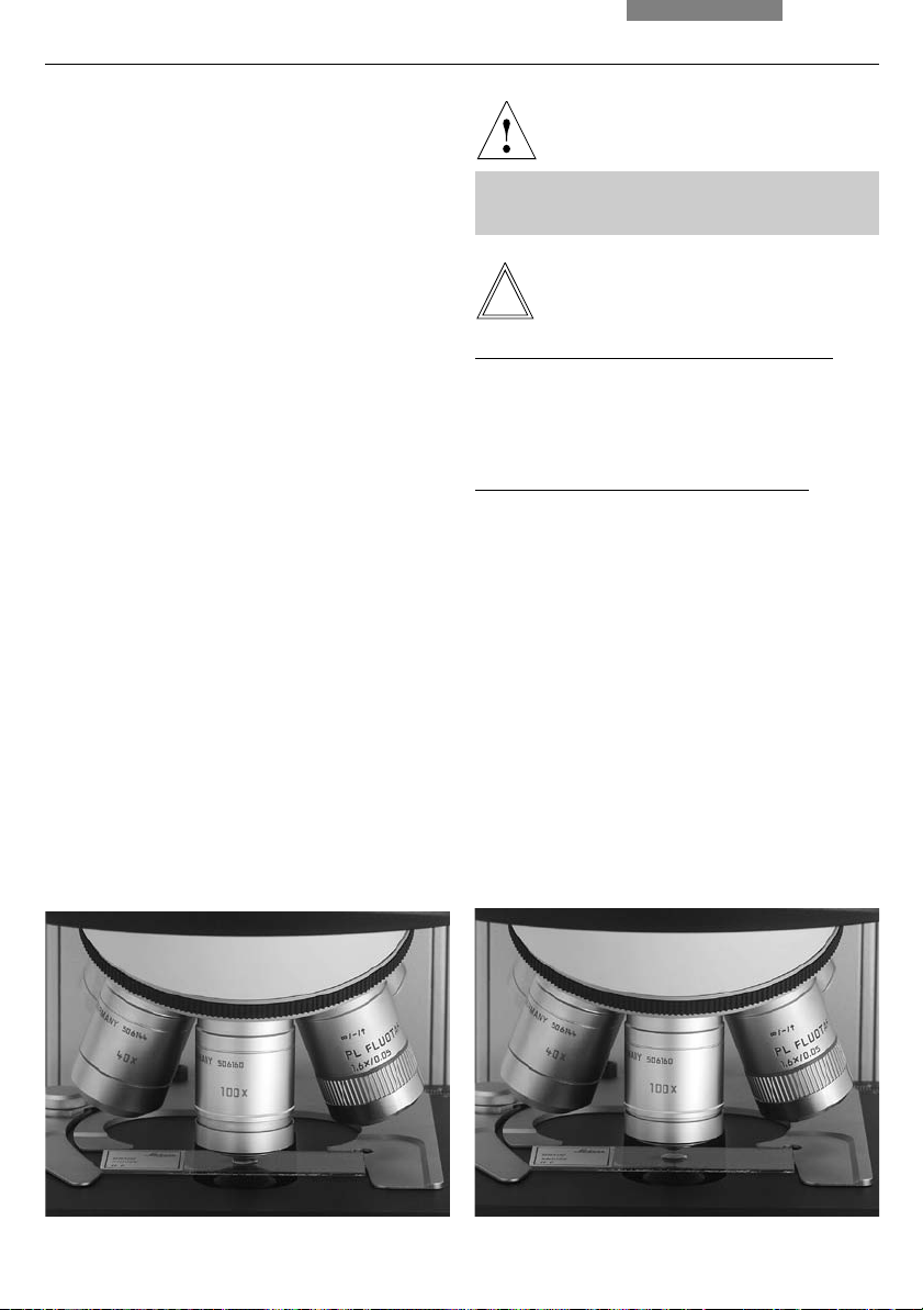
8.6 Objektive
Objektivwechsel
8. Bedienung
Achtung!
Die Objektive werden manuell in den Strahlengang eingeschwenkt. Achten Sie darauf, dass
der Revolver einrastet.
Beim Objektivwechsel sollten die Einstellungen
für
• Leuchtfeldblende → S. 41
• Aperturblende → S. 40
• Lichtintensität → S. 40
überprüft werden.
• Verwenden Sie bei Immersionsobjektiven das
entsprechende Immersionsmedium.
OIL: nur optisches Immersionsöl nach DIN/
ISO verwenden
Reinigung → S. 55
W: Wasserimmersion
IMM: Universalobjektiv für Wasser, Glyzerin,
Ölimmersion
Sicherheitsdatenblatt zum Immersionsöl beachten!
Hinweis:
Bei verriegelbaren Immersionsobjektiven drücken Sie zum Verriegeln die Frontpartie bis zum
Anschlag nach oben (ca. 2 mm). Nach einer
leichten Drehbewegung nach rechts ist das Objektiv verriegelt (Abb. 44).
Bei Objektiven mit Korrektionsfassung passen
Sie das Objektiv durch Drehen des Rändels an
die Dicke des Deckglases an.
Abb. 43 Immersionsobjektiv, entriegelt Abb. 44 Immersionsobjektiv, verriegelt
↔
↔
39
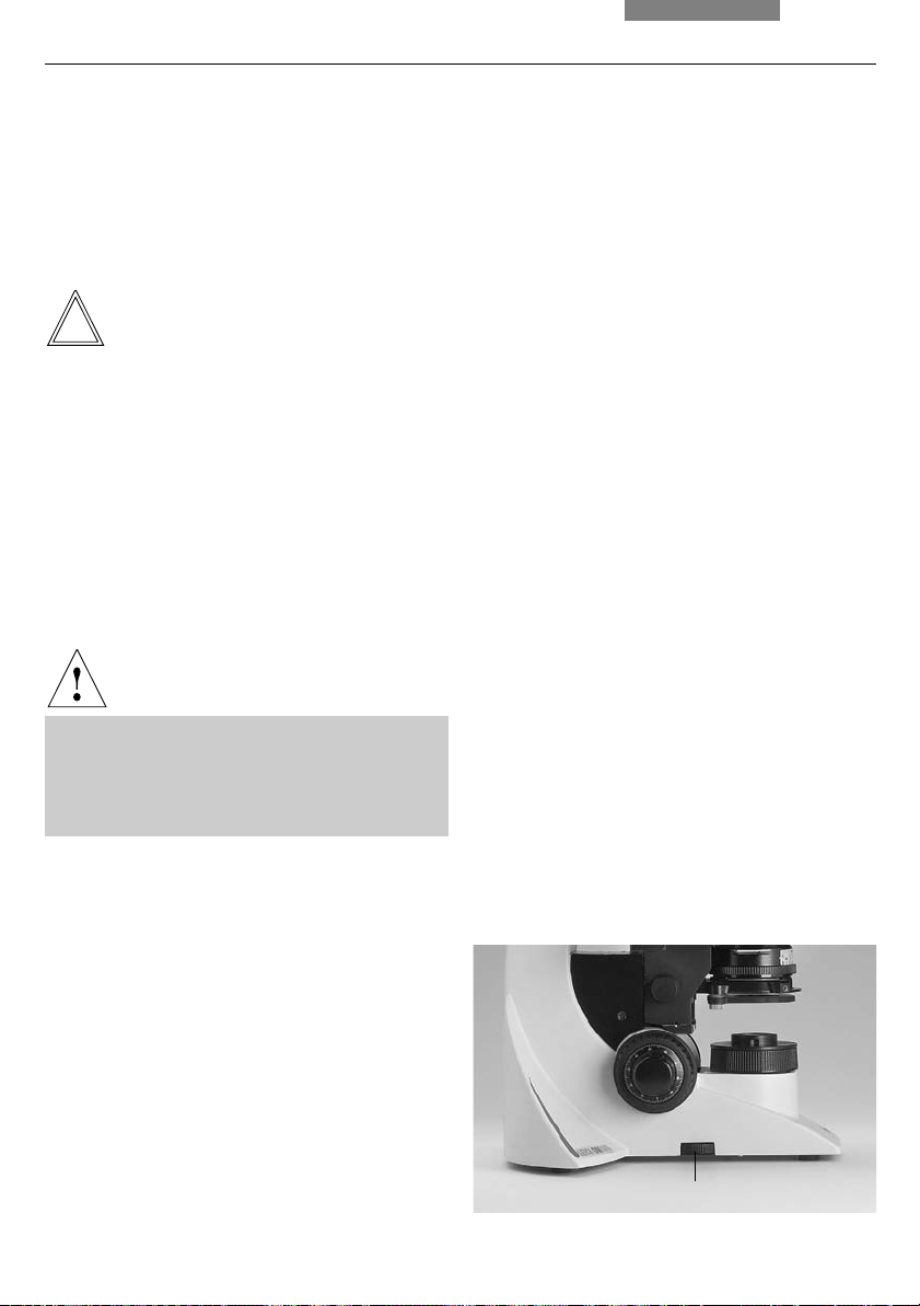
8. Bedienung
8.7 Lichtquellen
Durchlicht
Regeln Sie die Helligkeit am Stellrad (45.1) .
Die Zahlenwerte am Stellrad sind keine Absolutwerte, sie dienen nur einer reproduzierbaren
Einstellung.
Hinweis:
Die Objektivreihen
HI PLAN xx SL* und
HI PLAN CY xx SL*
(Synchronized Light) ermöglichen den Objektiv-
wechsel ohne zusätzlich die Lichtintensität anpassen zu müssen.
Fluoreszenz*
Schalten Sie die Lampe am Vorschaltgerät ein.
Achtung!
Mindestabstand des Lampenhauses von der
Wand, von Vorhängen, Tapeten, Büchern
u.a. brennbaren Gegenständen 10 cm!
Brandgefahr!
8.8 Aperturblende
Die Aperturblende (46.3) im Kondensor bestimmt
Auflösung, Tiefenschärfe und Kontrast des mikroskopischen Bildes. Die beste Auflösung erreicht man, wenn die Aperturen von Objektiv
und Kondensor etwa gleich sind.
Bei Einengen der Aperturblende unter die
Objektivapertur nimmt das Auflösungsvermögen
ab, der Kontrast wird dagegen angehoben. Eine
für das Auge merkliche Verminderung des Auflösungsvermögens tritt bei Schließen der
Aperturblende unter ca. 0,6x des Objektivs ein
und sollte möglichst vermieden werden.
Bei der Polarisationsmikroskopie ergibt ein Einengen der Aperturblende meist kräftigere Farben.
Die Aperturblende wird subjektiv nach Bildeindruck eingestellt, die Skala dient zur reproduzierbaren Einstellung ohne Zuordnung absoluter
Aperturwerte.
Beachten Sie die gesonderte Anleitung zum Vorschaltgerät!
40
Abb. 45
1 Helligkeitseinstellung
1
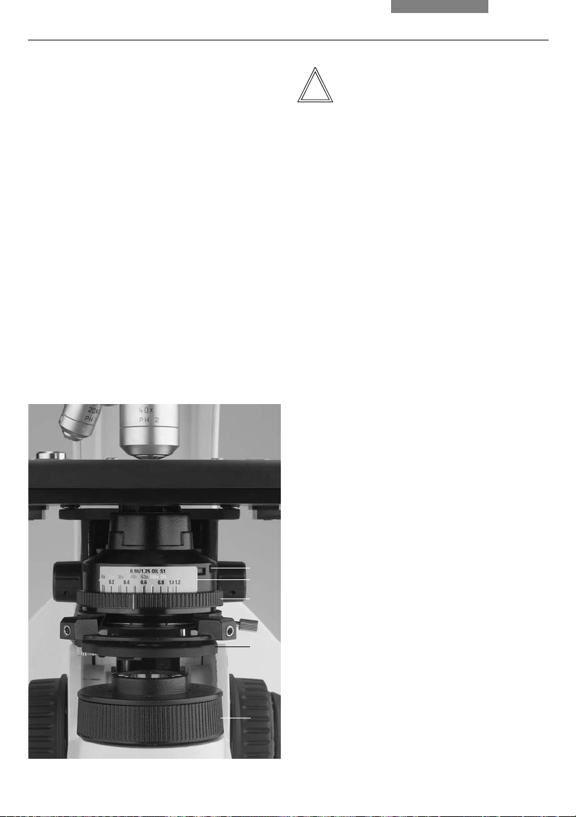
Farbkodierter Kondensor
Die Farbmarkierungen am Kondensor (46.2) korrespondieren mit den Farbringen der Objektive.
Beim Objektivwechsel kann eine geeignete
Aperturblendeneinstellung dadurch leicht gefunden werden, dass die Aperturblende auf die
entsprechende Farbmarkierung (entspricht 2/3
der objektivseitigen Apertur) gestellt wird.
Abb. 46 Kondensor CL/PH
1 Aufnahmeschlitz für Lichtringe u.ä.
2 Farbkodierung
3 Aperturblende
4 Filterhalter
5 Leuchtfeldblende
8. Bedienung
Achtung:
Die Aperturblende im Beleuchtungsstrahlengang dient nicht zur Einstellung der Bildhellig-
keit. Hierfür sind ausschließlich der Drehknopf
zur Helligkeitsregulierung bzw. neutrale Lichtdämpfungsfilter zu benutzen.
Eine Aperturblende im Objektiv wird im Normalfall voll geöffnet. Ein Einengen ergibt bei geringerer Bildhelligkeit:
Höhere Tiefenschärfe
Geringere Deckglasempfindlichkeit
Dunkelfeldeignung
Kontrastveränderung
8.9 Leuchtfeldblende
Die Leuchtfeldblende (46.5) schützt das Präparat
vor unnötiger Erwärmung und hält alles nicht zur
Abbildung benötigte Licht vom Objekt fern, so
dass der Kontrast gesteigert werden kann. Deshalb öffnet man sie immer nur so weit, dass das
beobachtete oder fotografierte Objektfeld gerade ausgeleuchtet wird. Ein Vergrößerungswechsel bedingt immer eine Anpassung der
Leuchtfeldblende.
1
2
3
4
5
41

9. Kontrastverfahren
9. Kontrastverfahren
9.1 Durchlicht
Objektivvergrößerung 2,5x*
Die Kondensoren CL/PH bzw. CLP/PH sind ohne
Zusatz ab einer Vergrößerung 4x verwendbar.
Bei Verwendung eines Streulichtschiebers* ist
auch die Vergrößerung 2,5x möglich, nicht jedoch bei Polarisation.
Die Kondensoren UCL bzw. UCLP sind ohne Zusatz ebenfalls ab einer Vergrößerung 4x verwendbar.
Bei Verwendung einer Anpassungslinse* (in der
Kondensorscheibe) ist auch die Vergrößerung
2,5 x möglich.
Vor dem Einschalten der Anpassungslinse muss
die Köhlersche Beleuchtung (→ S. 28) mit dem
Objektiv 4x oder 10x eingestellt werden.
Wechseln Sie danach zum Objektiv 2,5x,
schwenken Sie die Linse ein, öffnen Sie die
Aperturblende ganz und engen Sie die
Leuchtfeldblende ein.
Sind sichelförmige Abschattungen sichtbar,
muss die Linse zentriert werden. Stecken Sie
dazu beide Zentrierschlüssel von schräg hinten
in den Kondensor ein und verstellen Sie solange
bis die asymmetrischen Abschattungen verschwinden. Entfernen Sie die Zentrierschlüssel
und öffnen Sie die Leuchtfeldblende wieder.
Die Linse kann nur bis max. Objektivvergrößerung 20x benutzt werden. Köhlersche
Beleuchtung ist grundsätzlich nicht mehr exakt
möglich!
Der Kondensor Achr.Apl.0,9 (P) ist ohne Zusatz
ab einer Vergrößerung 4x verwendbar.
Bei ausgeklapptem Kondensorkopf ist die
Objektivvergrößerung 2,5x ohne Streuscheibe
möglich, bei eingeklapptem Kondensorkopf
muss die einsteckbare Streuscheibe verwendet
werden (max. Okularsehfeldzahl 22).
Objektive mit Vergrößerung < 10x werden mit
ausgeklapptem, mit Vergrößerungen ab 10x (bis
100x) mit eingeklapptem Kondensor verwendet.
Bei der Verwendung von schwenkbarem Polarisator (11 555 034) und beim Ausklappen des
Blaufilters (11 505 210 oder 11 505 211) muss der
äußere längere Kondensor-Klapphebel abgeschraubt werden.
Die optionale Streuscheibe* (11 505 219) bzw.
Kondensorlinse* (11 505 507) für kleinere Objektivvergrößerungen (1,25x–5x) wird mit der Öffnung auf den Kondensorkopf gelegt. Bei Verwendung von Vergrößerungen kleiner als 10x
wird die Streuscheibe/Kondensorlinse* beim
Ausklappen des Kondensorkopfes automatisch
in die Strahlengang eingeführt.
Objektivvergrößerungen 1,6x und 2,5x*
Mit den Kondensoren CL/PH bzw. CLP/PH, UCL
bzw. UCLP sind Vergrößerungen 1,6x und 2,5x
ebenfalls möglich, wenn der Kondensor komplett entfernt wird. Die Leuchtfeldblende wird
dann funktionell zur Aperturblende.
Hinweis:
Wenn das Mikroskop für Polarisation ausgerüstet ist, müssen zur Durchführung der anderen
Kontrastverfahren zunächst Analysator und Polarisator, sowie ggf. der Lambda-Plattenkompensator entfernt bzw. ausgeschwenkt werden.
42
 Loading...