


Leica CM3050 S
Cryostat
Instruction Manual
Leica CM3050 S – Cryostat
English V1.2– 11/2006
Always keep this manual near the instrument.
Read carefully prior to operating the instrument.
Serial No.: .............. ......................................................
Year of Manufacture: ...............................................
Country of Origin: Federal Republic of Germany
Issued by:
Leica Microsystems Nussloch GmbH Heidelberger Str. 17 - 19
D-69226 Nussloch Germany
Phone: +49 6224 143-0
Fax: +49 6224 143-200
Internet: http://www.histo-solutions.com
Important note
The information contained in this document represents state-of-the-art technology as well as the current state of knowledge.
Leica will not assume liability for errors that might be contained in this manual, nor for accidental damage or damage arising from the delivery, performance or use of this manual.
Therefore, no claims can be made based on the text and illustrations in this instruction manual.
Leica Microsystems Nussloch GmbH reserves the right to change technical specifications without notice since each of our products is subject to a policy of continuous improvement.
This document is protected under copyright laws. Leica Microsystems Nussloch GmbH retains all rights related to this documentation. Any reproduction of text and illustrations - or any parts thereof - in form of printing, photocopying, microfiches, or other methods, including electronic systems, requires the prior written permission of Leica Microsystems Nussloch GmbH.
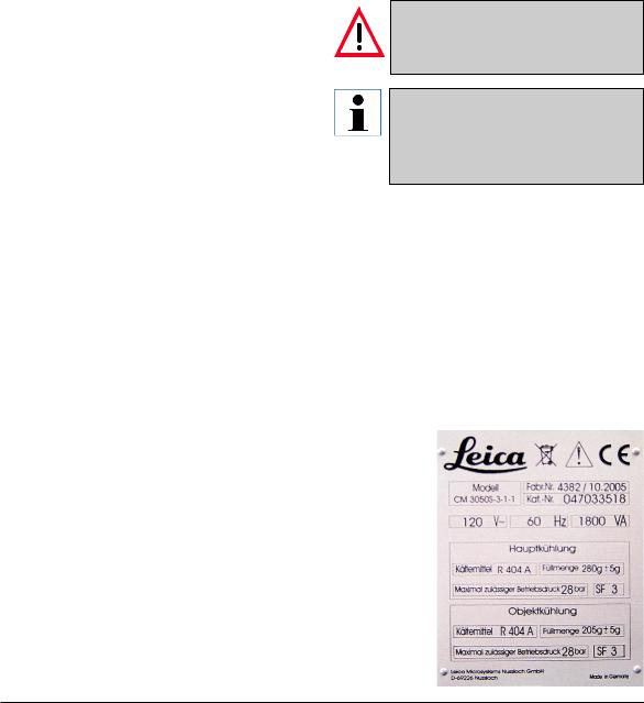
The serial number and the year of manufacture are specified on the nameplate at the back of the instrument.
© Leica Microsystems Nussloch GmbH
Leica CM 3050 S – Cryostat |
3 |

Table of Contents
1. |
Important information................................................................................................................ |
7 |
|
|
1.1 |
Symbols used in this manual and .................................................................................................... |
7 |
|
1.2 |
Designated use ................................................................................................................................... |
8 |
|
1.3 |
Qualification of personnel .......................................................................................................... |
8 |
2. |
Sicherheit .................................................................................................................................... |
9 |
|
|
2.1 |
General information on instrument design and safe handling .................................................... |
9 |
|
2.2 |
Integrated safety devices ................................................................................................................. |
9 |
|
2.2.1 |
Locking the handwheel ................................................................................................................... |
10 |
|
2.2.2 |
Centering the handwheel grip ........................................................................................................ |
10 |
|
2.2.3 |
Emergency stop function (instruments with sectioningmotor only) ........................................ |
11 |
|
2.2.4 |
Knife guard ........................................................................................................................................ |
11 |
|
2.3 |
Safety instructions: handling and operation of the instrument................................................. |
12 |
|
2.3.1 |
Transport ........................................................................................................................................... |
12 |
|
2.3.2 |
Site requirements ............................................................................................................................. |
12 |
|
2.3.3 |
Electrical connections ..................................................................................................................... |
12 |
|
2.3.4 |
Handling microtome knives/blades ............................................................................................... |
13 |
|
2.3.5 |
Knife guard/handwheel lock........................................................................................................... |
13 |
|
2.3.6 |
Motorized sectioning ....................................................................................................................... |
13 |
|
2.3.7 |
Defrosting/Handling frozen tissue ................................................................................................. |
13 |
|
2.3.8 |
Frozen parts of the instrument and frozen accessories ............................................................ |
13 |
|
2.3.9 |
Infectious/radioactive material ...................................................................................................... |
14 |
|
2.3.10 |
Disinfection and cleaning ............................................................................................................... |
14 |
|
2.3.11 |
Removing/reinstalling the microtome ........................................................................................... |
15 |
|
2.3.12 |
Display message ‘Dry microtome’ ................................................................................................. |
15 |
|
2.3.13 Maintenance .............................................................................................................................. |
15 |
|
3. |
Installation................................................................................................................................. |
16 |
|
|
3.1 |
Site requirements ............................................................................................................................. |
16 |
|
3.1.1 |
General site requirements .............................................................................................................. |
16 |
|
3.1.2 |
Electrical connections ..................................................................................................................... |
16 |
|
3.2 |
Unpacking and installation ............................................................................................................. |
16 |
|
3.2.1 |
Repacking .......................................................................................................................................... |
16 |
|
3.3 |
Standard delivery ............................................................................................................................. |
17 |
|
3.4 |
Installing/inserting accessories..................................................................................................... |
19 |
|
3.4.1 |
Installing the handwheel ................................................................................................................. |
19 |
|
3.4.2 |
Inserting the accessories ............................................................................................................... |
19 |
|
3.4.3 |
The footswitch .................................................................................................................................. |
20 |
|
3.5 Prior to switching on the instrument ........................................................................................ |
20 |
|
4 |
Instruction Manual V1.2 - 11/2006 |

|
|
Table of Contents |
|
|
|
|
|
|
|
|
|
4. |
Instrument Properties.............................................................................................................. |
21 |
|
|
4.1 |
Overview ............................................................................................................................................ |
21 |
|
4.2 |
Technical Data ........................................................................................................................... |
23 |
5. |
Operation ................................................................................................................................... |
25 |
|
|
5.1 |
Operating the instrument for the first time ................................................................................... |
25 |
|
5.2 |
Switching on/fuses........................................................................................................................... |
26 |
|
5.3 |
Control panel 1 .................................................................................................................................. |
27 |
|
5.3.1 |
Key functions in control panel 1..................................................................................................... |
27 |
|
5.3.2 |
Display functions in control panel 1 .............................................................................................. |
27 |
|
5.3.3 |
Display indications when switching on ........................................................................................ |
28 |
|
5.3.4 |
Menu functions: setting parameters of refrigeration, time and preset counter .................... |
29 |
|
5.3.5 |
Status display .................................................................................................................................... |
32 |
|
5.3.6 |
Indication of refrigeration state, section thickness setting and counters .............................. |
33 |
|
5.4 |
Control panel 2 .................................................................................................................................. |
34 |
|
5.4.1 |
Selecting a sectioning mode / ........................................................................................................ |
35 |
|
5.4.2 |
Setting the sectioning window....................................................................................................... |
36 |
|
5.4.3 |
Selecting sectioning speed ............................................................................................................ |
37 |
|
5.4.4 |
Emergency stop ................................................................................................................................ |
37 |
|
5.4.5 |
Coarse feed keys .............................................................................................................................. |
38 |
|
5.4.6 |
Trimming and sectioning functions ............................................................................................... |
39 |
|
5.4.7 |
Setting the section thickness ......................................................................................................... |
39 |
|
5.5 |
Daily operation of the instrument .................................................................................................. |
40 |
|
5.5.1 |
Freezing specimens onto specimen .............................................................................................. |
40 |
|
5.5.2 |
Freezing specimens onto specimen .............................................................................................. |
41 |
|
5.5.3 |
Optional accessories for freezing .................................................................................................. |
41 |
|
5.5.4 |
Inserting specimen discs into the .................................................................................................. |
42 |
|
5.5.5 |
Specimen orientation....................................................................................................................... |
42 |
|
5.5.6 |
Trimming / sectioning ...................................................................................................................... |
43 |
|
5.6 |
Finishing work ................................................................................................................................... |
44 |
|
5.6.1 |
Daily routine steps............................................................................................................................ |
44 |
|
5.6.2 |
Switching off the instrument for a ................................................................................................. |
44 |
|
5.7 |
Defrosting .......................................................................................................................................... |
45 |
|
5.7.1 |
Automatic chamber defrost cycle ................................................................................................. |
45 |
|
5.7.2 |
Manual chamber defrost cycle ...................................................................................................... |
46 |
|
5.7.3 Defrosting the specimen head ................................................................................................ |
46 |
|
Leica CM3050S – Cryostat |
5 |

Table of contents
6. |
Troubleshooting, applications tips ....................................................................................... |
47 |
|
|
6.1 |
Displayed error messages .............................................................................................................. |
47 |
|
6.1.1 |
Other error indications .................................................................................................................... |
47 |
|
6.2 |
Potential problems - causes and remedies ................................................................................. |
48 |
|
6.3 |
Reference chart for temperature settings (in minus °C) .................................................... |
52 |
7. |
Disinfection, cleaning and maintenance ............................................................................ |
53 |
|
|
7.1 |
Safety instructions ........................................................................................................................... |
53 |
|
7.2 |
Spray disinfection with Leica Cryofect ......................................................................................... |
53 |
|
7.3 |
Disinfection with conventional ....................................................................................................... |
54 |
|
7.4 |
Cleaning ............................................................................................................................................. |
54 |
|
7.5 |
Removing / reinstalling the microtome ......................................................................................... |
55 |
|
7.5.1 |
Removing the microtome ................................................................................................................ |
55 |
|
7.5.2 |
Disassembling the specimen head................................................................................................ |
55 |
|
7.5.3 |
Reinstalling the microtome ............................................................................................................. |
56 |
|
7.6 |
Exchanging the fluorescent light lamp................................................................................... |
57 |
8. |
Warranty and service .............................................................................................................. |
58 |
|
9. |
Appendix .................................................................................................................................... |
59 |
|
|
1. |
Electrohydraulic height adjustment .............................................................................................. |
59 |
|
2. |
Ordering information - accessories ....................................................................................... |
62 |
10. |
EC Declaration of Conformity ..................................................................................... |
63 |
|
11. |
Decontamination Certificate (master) .................................................................................... |
64 |
|
6 |
Instruction Manual V1.2 - 11/2006 |
|
1. Important information |
|
|
|
|
The chapters of the Leica CM3050 S cryostat |
1.1 Symbols used in this manual and |
instruction manual: |
their meaning |
Chapter 1 Structure of the manual:
•Table of contents
•Important information on this manual
Chapter 2 Safety
•Read this chapter before operating the instrument!
Chapter 3 Installation
•Unpacking and installation
•Standard delivery, information on accessories
Chapter 4 Instrument properties
•Overview
•Technical data
Chapter 5 Operation
•Controls
•Setup, daily use and shut down
Chapter 6 Trouble shooting and applications tips
•Operating errors
•Display error messages
•Temperature reference chart
Chapter 7 Disinfection, cleaning and maintenance
Chapter 8 Warranty and service
Chapter 9 Electrohydraulic height adjustment Ordering information accessories EC Declaration of Conformity
Warnings
appear in a grey box and are marked by a warning triangle 
Notes
i.e. important user information appears in a grey box and is marked by an information  symbol.
(5)Figures in brackets refer to item
(Fig.5) |
numbers in drawings or to the |
|
drawings themselves. |
Instrument type:
All information given in this instruction manual applies only to the instrument type indicated on the title page.
A name plate, indicating the instrument serial number, is attached to the back of the instrument.
Required information for all inquiries:
For any inquiries please specify:
•Instrument type
•Serialnumber
Leica CM 3050 S – Cryostat |
7 |
1.Important information
General
This instruction manual includes important instructions and information related to the operating safety and maintenance of the instrument.
The instruction manual is an important part of the product. It must be read carefully before using the instrument for the first time and must always be kept with the instrument.
If additional requirements, which exceed the scope of this manual, are imposed by regula-tions and/or laws on accident prevention and environmental protection in the country of operation, appropriate instructions for compliance with such requirements must be added to this manual.
Read this instruction manual carefully before attempting to use or operate the instrument.
Please pay particular attention to chapter 2 (safety features, safety instructions). - Please read this information, even if you are already familiar with the operation and use of other Leica products.
1.2Designated use
The Leica CM3050S is a powerful cryostat for routine as well as research applications in biology, medicine and industry.
The instrument has been designed for rapid freezing and sectioning of tissue samples.
The instrument has not been designed for unattended storage of tissue material.
The instrument may only be operated within the scope of its designated use as described above and as per the instructions given in this manual.
Any other use of the instrument is considered improper.
1.3Qualification of personnel
The Leica CM3050S may only be operated by trained laboratory personnel.
All laboratory personnel designated to operate the instrument must carefully read the present instruction manual prior to starting work with the instrument.
8 |
Instruction Manual V1.2 - 11/2006 |

2. Sicherheit
2.1General information on instrument design and safe handling
This instrument has been built and tested in accordance with the following safety regulations on electrical measuring, control, regulating and laboratory devices:
•DIN EN 292
•DIN EN 61010-1
•EN 50082-1
•EN 55011
•IEC 1000-4
as well as according to the international quality standard
• DIN ISO 9001
In order to maintain this condition and to ensure safe operation, the operator must observe the instructions and warnings contained in this instruction manual.
2.2Integrated safety devices
The instrument is equipped with the following safety devices:
•Handwheel lock
•Handwheel grip centering
•Emergency stop function
(instruments with sectioning motor only)
•Knife holder equipped with knife guard
The safety devices installed by the manufacturer of the instrument only constitute the basis of accident prevention.
Mainly responsible for accident-free operation is above all the institution which owns the instrument and, in addition, the designated personnel who operate, service or repair the instrument.
Leica CM3050 S – Cryostat |
9 |
2.Safety
2.2.1 Locking the handwheel
Always cover the cutting edge with the knife guard and lock the handwheel:
•Prior to doing any work on knife and/or specimen.
•Prior to exchanging specimens.
•During work breaks.
The handwheel can be locked in 2 positions:
•with the grip in the uppermost position (left),
•with the grip in the lowest position (right).
2
2
Locking:
•Rotate handwheel, until grip (1) is in upper or lower position.
•To lock, press pin (2) to the right into position (2b).
--> The upper locking position for pin (2) is marked by a black dot (4).
Instruments with sectioning motor:
The sectioning motor is now blocked.
All instruments:
The message ‘LOCKED’ in the display of control panel 1 indicates that the handwheel has been locked:
C |
T |
- |
3 |
0 |
° |
C |
|
|
O |
T |
- |
3 |
5 |
° |
C |
|
|
|
|
|
|
|
|
|
|
|
|
|
|
|
|
|
|
|
|
|
L |
O |
C |
K |
E |
D |
|
|
|
|
|
|
|
|
|
|
|
|
|
|
|
|
|
|
|
|
|
Unlocking:
•To unlock, push locking pin (2) to the left into position (2a).
•Display indication ‘LOCKED’ disappears.
Instruments with sectioning motor:
The sectioning motor can now be activated again.
2.2.2 Centering the handwheel grip
During motorized sectioning, for safety reasons always center the handwheel grip!
•To center grip (1), pull outwards and pivot into center of handwheel.
•When released, the grip locks into position.
10 |
Instruction Manual V1.2 - 11/2006 |
2.Safety
2.2.3Emergency stop function (instruments with sectioning motor only)
The emergency stop is activated via the red emergency stop button in control panel 2 or via the footswitch
Control panel 2
Footswitch
Activating the emergency stop function
•Press emergency stop button or step on footswitch forcefully.
-->  STOP (red) lights up.
As soon as the emergency stop function is activated, the sectioning motor stops.
Deactivating the emergency stop
•To deactivate, rotate emergency stop button in direction of arrow.
If the emergency stop function has been activated by the footswitch, unlocking is not necessary (func-tion is unlocked as soon as the footswitch is released).
2.2.4 Knife guard
All knife holders are equipped with a knife guard (--> see separate instruction manuals on knife holders).
Always cover the cutting edge with the knife guard:
•Prior to doing any work on knife and/ or specimen.
•Prior to exchanging specimens.
•During work breaks.
Leica CM3050 S – Cryostat |
11 |

2.Safety
2.3Safety instructions: handling and operation of the instrument
2.3.1 Transport
•To avoid severe damage to the instrument by running it while the compressor oil is displaced from its regular position:
•Do not tilt the instrument,
only transport in an upright position.
•After transport, wait at least 4 hours be-
fore turning the instrument on.
-->The compressor oil may have been displaced during transport and must settle to its original position before switchingthe instrument on. Otherwise, the instrument may be severely damaged.
2.3.2 Site requirements
•Do not operate the instrument in rooms with explosion hazard.
•To ensure proper instrument function maintain a minimum distance of 10 cm between walls and/or furniture and all sides of the instrument!
2.3.3 Electrical connections
•Do not use extension cords for connecting the instrument to mains.
-->Fire hazard!
-->Instrument malfunctions caused by voltage drop.
•During the start-up phase of the compressor, the nominal voltage must not drop below the values specified in chapter 4.2 ‘Technical data’!
-->The compressor needs a start-up current at between 25 and 35 A (see chapter 4.2 ‘Technical data’)
•Ensure uniform current supply according to specifications.
-->Electrical power supply deviating from specifications damages the instrument.
•Therefore, arrange for the electrical installations on site to be checked by a trained professional and make sure any necessary upgrades are installed!
•Have the circuit protected by a fuse of its own!
•Do not connect any other consumers to the same circuit.
•Prior to connecting the instrument to mains, make sure the electrical power supply in your laboratory corresponds to the values indicated on the instrument nameplate (located at the rear of the instrument)!
12 |
Instruction Manual V1.2 - 11/2006 |

2.Safety
2.3.4 Handling microtome knives/blades
•Danger!
-->Microtome knives and disposable blades have extremely sharp cutting edges and can cause serious injuries. Therefore:
•Handle knives / blades with utmost care.
•Never leave any knives / blades in unprotected places!
•Never place a knife, no matter where, with the cutting edge facing upwards.
•Never try to catch a falling knife.
•Always insert the specimen before inserting the knife.
2.3.5 Knife guard/handwheel lock
•Always cover the cutting edge with the knife guard and lock the handwheel:
•Prior to doing any work on knife and / or specimen.
•Prior to exchanging specimens.
•During work breaks.
2.3.6 Motorized sectioning
•Do not interrupt sectioning / trimming by setting the sliding potentiometer to zero speed! -->This does not really switch the sectioning function off - it only operates at ‘0’ speed.
If the sliding potentiometer is accidentally moved, the instrument will resume sectioning immediately (risk of injury)!
•During motorized sectioning, always center the handwheel grip!
2.3.7 Defrosting/Handling frozen tissue
•Never leave specimens unattended in the cryochamber over an extended period of time!
-->In case of power failure or instrument failure, or during the automatic defrost cycle, tissue material can be destroyed.
•During the defrost cycle the cryochamber is partially warmed. - Therefore:
•Remove sensitive specimens from the chamber prior to defrosting.
•If automatic defrosting is programmed to take place during the night, remember to remove all specimens from the cryochamber prior to leaving work.
2.3.8Frozen parts of the instrument and frozen accessories
•Prolonged contact of bare skin to frozen surfaces of the instrument or to frozen accessories (specimen discs, knife holder, shelves etc.) can cause frostbite.
• Wear protective gloves.
Leica CM3050 S – Cryostat |
13 |

2.Safety
2.3.9 Infectious/radioactive material
•Danger!
Use caution when working with potentially infectious specimens:
-->Risk of infection!
•When working with potentially infectious / radioactive specimens:
•Wear protective clothes (gloves, protective boots, mask, lab coat), in compliance with radiation safety regulations and/or in-house regulations on handling infectious / radioactive material.
•When working with radioactive specimens:
•Comply with applicable radiation safety regulations!
•Dispose of radioactive specimen waste according to applicable regulations.
2.3.10 Disinfection and cleaning
•Prior to disinfection, switch the instrument off and unplug it from mains.
•For removal of the microtome from the cryochamber see chapter 2.3.11 ‘ Removing the microtome’.
•For disinfection, wear protective gear: (gloves, mask, lab coat etc.)!
•For disinfection, only use alcohol-based disinfectants!
•Do not use solvents (xylene, acetone etc.) for cleaning or disinfection!
•Do not spray disinfectants into the evaporator!
-->Risk of icing!
•Explosion hazard when working with alcohol: Make sure the premises are appropriately ventilated!
•When using disinfectants and detergents, comply with all safety instructions supplied by the manufacturer of the product!
•Dispose of waste liquids from disinfection/ cleaning as well as of sectioning waste according to applicable regulations on disposal of special category waste!
•Disinfected accessories must be thoroughly dry when reinserting them into the chamber!
-->Risk of icing!
•Make sure the chamber is completely dry before switching the instrument back on:
-->Explosion hazard through alcohol vapors! -->Risk of icing!
14 |
Instruction Manual V1.2 - 11/2006 |

2.Safety
2.3.11Removing/reinstalling the microtome
•Before removing the microtome:
•Switch instrument off.
•Unplug from mains.
•Place handwheel grip in lowest position and lock.
-->When removing the microtome, the specimen head must always be lokked in the lowest position. Otherwise the upper part of the slot cover might be bent and consequently damaged!
•When removing the microtome:
•Wear gloves when removing the microtome while it is still frozen.
-->Risk of frost bite!
•On instruments with specimen cooling:
do not distort the refrigerating tube!
If distorted it might break, causing extremely cold refrigerant to escape. - -
>Risk of frost bite!
•Before reinstalling the microtome:
• Microtome must be completely dry. |
-- |
|
>Humidity in the interior of the micro- |
|
|
tome freezes and causes |
|
|
microtome |
malfunctions and/or |
|
damage to the |
microtome. |
|
•All accessories/tools removed from the cryochamber must be thoroughly dry before putting them back into the chamber!
-->Risk of icing!
2.3.12 Display message ‘Dry microtome’
•If the error message ‘Dry Microtome’ is displayed in control panel 1, the following has happened:
•Cryochamber refrigeration has been interrupted for an extended period of time (e.g. power failure), causing the chamber temperature to rise into the positive digits.
•If this message appears, do not switch on the instrument but remove the microtome from the chamber, disinfect, if necessary, and dry thoroughly before reinstalling it into the chamber (see chapter 7.1 to 7.5).
2.3.13 Maintenance
•Only technical service engineers authorized by Leica may access the internal components of the instrument for service and repair.
•The fluorescent light lamp (chamber illumination), unless broken or splintered, can be replaced by the user:
•Switch off mains switch!
•Unplug the instrument from mains!
•If the lamp is broken or splintered:
Have lamp replaced by Leica Technical Service!
-->Risk of injury!
•Use only those replacement lamps that correspond to technical specification (see chapter 4.2 ‘Technical Data’).
Leica CM3050 S – Cryostat |
15 |
3.Installation
3.1Site requirements
Make sure to read and follow all safety instructions in chapter 2.3.2 ‘Site requirements’!
3.1.1 General site requirements
•No direct sunlight.
•Electrical power supply within distance (length of power cord = approx. 4 meters - do not use extension cords!).
•No draft (caused by air conditioning etc.).
•Even floor surface.
•Practically vibration-free floor.
•Handwheel easily accessible.
•Room temperature constantly below +22 °C.
•Relative humidity of air maximum 60 %.
High ambient temperature and/or high air humidity negatively affect instrument cooling performance!
3.1.2 Electrical connections
Make sure to read and follow all safety instructions in chapter 2.3.3 ‘Electrical connections’!
3.2Unpacking and installation
Unpacking instructions are always located in a transparent protective envelope on the outside of the instrument shipping crate.
Make sure to read and follow all safety instructions provided in chapter 2.3.1 ‘Transport’ and on the unpacking instructions!
3.2.1 Repacking
We recommend to keep the original shipping crate and the unpacking instructions for the Leica CM3050 S.
For repacking, proceed as per unpacking instructions, in reverse order.
Available models
•Basic instrument
-with sectioning motor
-without specimen cooling
•Basic instrument
-without sectioning motor
-with specimen cooling
•Basic instrument
-with sectioning motor
-with specimen cooling
16 |
Instruction Manual V1.2 - 11/2006 |
|
|
|
|
|
|
3. |
Installation |
|
|
|
|
|
|
|
|
|
|
3.3 |
Standard delivery |
|
|
|
|
|
|
|
|
1 |
Cryostat with microtome............................................................................. |
|
|
0460 32037 |
|
||
|
1 |
Handwheel with marking, antibacterial ................................................... |
|
|
0471 42558 |
|
||
|
1 |
Heat extractor, stationary........................................................................... |
|
|
0369 11197 |
|
||
|
1 |
Low-temperature stabilizer for heatextractor ........................................ |
|
|
0452 27919 |
|
||
|
1 |
90° prism for direct specimen freezing on specimen head |
|
|
||||
|
|
with clamping screw to facilitate specimen trimming .......................... |
|
0443 25949 |
|
|||
|
1 |
Set of specimen discs ................................................................................. |
|
|
0470 43550 |
|
||
|
|
- 4 Specimen discs, 25 mm ......................................................................... |
|
|
0416 19275 |
|
||
|
|
- 4 Specimen discs, 30 mm ......................................................................... |
|
|
0370 08587 |
|
||
|
1 |
Storage shelf, right ...................................................................................... |
|
|
0443 25723 |
|
||
|
1 |
Storage shelf, left |
......................................................................................... |
|
|
0443 33549 |
|
|
|
1 |
Section waste tray ....................................................................................... |
|
|
0400 26817 |
|
||
|
1 |
Foot switch with protective guard ............................................................ |
|
|
0502 29977 |
|
||
|
1 |
Rubber mat .................................................................................................... |
|
|
|
0443 25732 |
|
|
|
1 |
Freezing shelf cover .................................................................................... |
|
|
0443 30783 |
|
||
|
1 |
Brush shelf .................................................................................................... |
|
|
|
0398 13088 |
|
|
|
1 |
Tool set........................................................................................................... |
|
|
|
|
0436 43463 |
|
|
|
-1 Brush, fine ................................................................................................. |
|
|
|
0183 28642 |
|
|
|
|
-1 Leica-brush............................................................................................... |
|
|
|
0183 30751 |
|
|
|
|
-1 Allen key, size 1.5 ..................................................................................... |
|
|
0222 10050 |
|
||
|
|
-1 Allen key, size 2.5 ..................................................................................... |
|
|
0222 04137 |
|
||
|
|
-1 Allen key, size 3.0 ..................................................................................... |
|
|
0222 04138 |
|
||
|
|
-1 Allen key, size 4.0 ..................................................................................... |
|
|
0222 04139 |
|
||
|
|
-1 Allen key with spherical ................................................head, size 4.0 |
|
|
0222 32131 |
|
||
|
|
-1 Allen key, size 5.0 ..................................................................................... |
|
|
0222 04140 |
|
||
|
|
-1 Allen key with handle, ...............................................................size 5.0 |
|
|
0194 04760 |
|
||
|
|
-1 Allen key, size 6.0 ..................................................................................... |
|
|
0222 04141 |
|
||
|
|
-1 Single-head wrench, ..................................................................size 13 |
|
|
0330 33149 |
|
||
|
|
-1 Single-head wrench, ..................................................................size 16 |
|
|
0330 18595 |
|
||
|
1 |
Bottle of OCT-Compound, mounting medium |
|
|
|
|
||
|
|
for cryosectioning, ...........................................................................125 ml |
|
|
0201 08926 |
|
||
|
1 |
Bottle of cryostat ........................................................oil, type 407, 50 ml |
|
|
0336 06098 |
|
||
|
1 |
Pair of cut resistant ............................................................gloves, size S |
|
|
0340 40859 |
|
||
|
1 |
Instruction manual ........................................Leica CM3050 S - G/E/F/S |
|
|
0708 37109 |
|
||
In addition to the above: |
|
|
|
|
|
|
|
|
Instruments with specimen cooling: |
Configured instruments: |
Instruments with sectioning motor: |
||||||
1 |
90° Prism |
|
1 |
Knife holder base |
1 |
Footswitch with |
||
|
for low temperature quick freezing |
1 |
Knife holder with accessories |
|
protective guard |
|||
|
|
|
|
|
|
|
|
|
Leica CM 3050 S – Cryostat |
|
|
|
|
|
17 |
|
|
3.Installation
In addition to the above:
•Instruments with specimen cooling:
1 90° Prism for low temperature quick freezing
•Configured instruments: 1 Knife holder base
1 Knife holder with accessories
•Instruments with sectioning motor: 1 Footswitch with protective guard
Further accessories:
Further accessories which you ordered will be included in the box containing the standard delivery items.
Knife holders are delivered with anti-roll guide, knife guard, and a separate instruction manual.
In case of non-configured instruments, the knife holder is not a part of standard delivery but must be ordered separately.
•Check all delivered parts against the packing list and against your order to verify whether the delivery is complete!
If there is any difference, contact your local Leica office immediately.
18 |
Instruction Manual V1.2 - 11/2006 |
3.Installation
3.4 Installing/inserting accessories
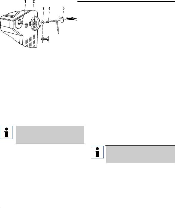
3.4.1 Installing the handwheel
•Insert pin (1) of the handwheel shaft into hole (2).
•Place spring washer (3) onto screw (4) as shown.
•Tighten screw (4) with an Allen key.
•Cover with selfadhesive disc (5).
For purposes of transport (e.g. narrow doors), the handwheel can be removed.
•To remove the handwheel, proceed as described above but in reverse order.
3.4.2 Inserting the accessories
•Place the rubber mat on top of the housing.
•Insert the storage shelves into the cryochamber.
•Install the stationary heat extractor into the quick-freeze shelf (see also drawing in chapter 5.5.1 ‘Freezing specimens onto specimen discs’).
•Insert the low temperature stabilizer into the quick freeze shelf (it must be located in the pivoting range of the heat extractor - see also drawing in chapter 5.5.1 ‘Freezing specimens onto specimen discs’).
•Insert section waste tray and brush shelf.
•Install knife holder base onto microtome base plate and clamp.
•Install knife holder and clamp (see knife holder instruction manual for details).
•Place knife case with knife into chamber to precool.
•Place all tools needed for section preparation into the chamber.
•Close the sliding window.
For a complete overview of all individual parts:
--> see Chapter 4.1 ‘Overview’.
Leica CM 3050 S – Cryostat |
19 |

3.Installation
3.4.3 The footswitch
Function
The footswitch performs the same task as the RUN/STOP and RUN/ENABLE keys (activating/ deactivating motorized sectioning / trimming). In addition, the footswitch can be used to activate the emergency stop function.
Models with footswitch:
All instruments with sectioning motor.
Important note:
In all instrument models that are delivered with footswitch, the footswitch must be installed! - Otherwise the instruments are not functional.
Connecting the footswitch
• Insert footswitch into port (1) and secure.
1
3.5Prior to switching on the instrument
After transport, observe a waiting period of at least 4 hours before turning the instrument on! - See also safety instructions in chapter 2.3.1 ‘Transport’.
Have you observed all safety instructions in chapters 2.3.2 ‘Site requirements’ and 2.3.3 ‘Electrical connections’?
If not:
--> Please read chapters 2.3.2 and 2.3.3!
•Insert mains plug into wall outlet.
•Continue with chapter 5.1 ‘Setting up the instrument’.
20 |
Instruction Manual V1.2 - 11/2006 |
 Loading...