


LeicaDM1000
Operating manual Bedienungsanleitung Mode d’emploi
M I C R O S Y S T E M S
Published September 2004 by/ Publiée en septembre 2004 par/ Herausgegeben September 2004 von:
Leica Microsystems Wetzlar GmbH
Ernst-Leitz-Strasse
D-35578 Wetzlar (Germany)
Responsible for contents/ Responsable du contenu rédactionnel/ Verantwortlich für den Inhalt:
Dr. Jasna Röth, Peter Schmitt
(Clinical Microscopy, Product Management)
Holger Grasse
(Safety Officer according to MPG §30/ Sicherheitsbeauftragter nach MPG §30/ Responsable de la sécurité conformément à la loi relative aux dispositifs médicaux, §30)
In case of questions, please contact the hotline/ Pour toute question, contacter notre service d’assistance téléphonique/
Bei Fragen wenden Sie sich bitte an die Hotline:
Phone/Tel./Tél. |
+49 (0) 64 41-29 22 86 |
Fax |
+49 (0) 64 41-29 22 55 |
E-mail/Email/Courriel |
MQM-Hotline@leica- |
|
microsystems.com |
LeicaDM1000
Operating Manual
3

Copyrights
Copyrights
All rights to this documentation are held by Leica Microsystems Wetzlar GmbH. Reproduction of text or illustrations (in whole or in part) by print, photocopy, microfilm or other method (including electronic systems) is not allowed without express written permission from Leica Microsystems Wetzlar GmbH.
The instructions contained in the following documentation reflect state-of-the-art technology and knowledge standards. We have compiled the texts and illustrations as accurately as possible. Nevertheless, no liability of any kind may be assumed for the accuracy of this manual’s contents. Still, we are always grateful for comments and suggestions regarding potential mistakes within this documentation.
The information in this manual is subject to modification at any time and without notification.
4
|
|
|
|
|
|
|
Contents |
|
|
|
|
|
|
|
|
||
|
|
|
|
|
|
|
|
|
Contents |
|
|
|
|
|
|
|
|
1. |
Important Notes about this Manual ...... |
6 |
8.4 |
Tubes |
........................................................ |
|
|
37 |
|
|
|
8.5 |
Eyepieces .................................................... |
38 |
|||
2. |
Intended Purpose of the Microscope ... |
7 |
8.6 |
Objectives ................................................... |
39 |
|||
|
|
|
8.7 |
Light Sources ............................................. |
40 |
|||
3. |
Safety Notes ............................................... |
8 |
8.8 |
Aperture Diaphragm ................................. |
40 |
|||
3.1 |
General Safety Notes ............................... |
8 |
8.9 |
Field Diaphragm ......................................... |
41 |
|||
3.2 |
Electrical Safety ........................................ |
8 |
9. |
Contrast Methods |
42 |
|||
|
|
|
||||||
4. |
Overview of the Instrument .................... |
10 |
9.1 |
Transmitted Light ....................................... |
42 |
|||
|
|
|
|
9.1.1 |
Brightfield ......................................... |
43 |
||
5. |
Unpacking the Microscope .................... |
14 |
|
9.1.2 |
Phase Contrast ................................ |
44 |
||
|
|
|
|
9.1.3 |
Darkfield ........................................... |
44 |
||
6. |
Assembling the Microscope .................. |
16 |
|
9.1.4 |
Oblique Illumination ....................... |
45 |
||
6.1 |
Stage ............................................................ |
16 |
|
9.1.5 |
Polarization ...................................... |
45 |
||
6.2 |
Condenser ................................................... |
18 |
9.2 |
Fluorescence .............................................. |
46 |
|||
6.3 |
Tube and Eyepieces .................................. |
19 |
10. |
Measurements with the Microscope |
47 |
|||
6.4 |
Objectives ................................................... |
19 |
||||||
6.5 |
Light Source - Transmitted Light Axis ... |
20 |
10.1 |
Linear Measurements .............................. |
47 |
|||
6.6 |
Components for |
|
10.2 |
Thickness Measurements ....................... |
48 |
|||
|
Fluorescence Applications ...................... |
21 |
10.3 |
Differentiation of Gout / Pseudo Gout |
... 49 |
|||
|
6.6.1 Fluorescence Illuminator .............. |
21 |
11. |
Troubleshooting |
51 |
|||
|
6.6.2 106 z Lamp Housing ........................ |
21 |
||||||
6.7 |
Analyzer and Polarizer* .......................... |
24 |
12. |
Care of the Microscope |
54 |
|||
6.8 |
Lambda Plate Compensator .................... |
24 |
||||||
6.9 |
Optional Accessories ............................... |
25 |
12.1 |
Dust Cover .................................................. |
54 |
|||
6.10 |
Connection to the Power Supply ............ |
27 |
12.2 |
Cleaning ....................................................... |
54 |
|||
|
|
|
12.3 |
Handling Acids and Bases ...................... |
55 |
|||
7. |
Startup ......................................................... |
28 |
12.4 |
Changing Fuses .......................................... |
55 |
|||
7.1 |
Switching on the Microscope ................. |
28 |
13. |
Essential Wear and Spare Parts |
56 |
|||
7.2 |
Köhler Illumination .................................... |
28 |
||||||
7.3 |
Checking Phase Contrast Rings ............. |
29 |
14. |
Retrofitting Components |
57 |
|||
7.4 |
Adjusting the Light Sources .................... |
31 |
||||||
|
|
|
14.1 |
Equipping the Condenser Disk ................ |
57 |
|||
8. |
Operation .................................................... |
35 |
15. |
Index |
|
|
|
59 |
8.1 |
Switching on ............................................... |
35 |
............................................................ |
|
|
|||
8.2 |
Stages and Object Displacement ........... |
35 |
16. |
EU Declaration of Conformity |
60 |
|||
8.3 |
Focusing ...................................................... |
36 |
||||||
5
1. Important Notes about this Manual
1.ImportantNotesaboutthisManual
Caution!
This operating manual is an essential component of the microscope, and must be read carefully before the microscope is assembled, put into operation or used.
Text symbols, pictograms and their meanings:
(1.2)
→ p.20
!
This operating manual contains important instructions and information for the operational safety and maintenance of the microscope and accessories. Therefore, it must be kept and taken care of.
Numbers in parentheses, such as "(1.2)", correspond to illustrations (in the example, Figure 1, Item 2).
Numbers with pointer arrows (for example → p.20), point to a certain page of this manual.
Caution!
Special safety instructions within this manual are indicated with the triangle symbol shown here, and have a gray background.
Caution! The microscope and accessories can be damaged when operated incorrectly.
|
Explanatory note. |
* |
Item not contained in all configurations. |
|
6

2. Intended Purpose of the Microscope
2.IntendedPurposeoftheMicroscope
The Leica DM1000 microscope, to which this user manual belongs, is designed for biological routine and research applications. This includes the examination of samples taken from the human body with a view to provide information on physiological or pathological states or congenital abnormalities, or to determine the safety and compatibility with potential recipients, or to monitor therapeutic measures.
The above-named microscope complies with the Council Directive 98/79/EEC concerning in vitro diagnostics. It also conforms to the Council Directives 73/23/EEC concerning electrical apparatus and 89/336/EEC concerning electromagnetic compatibility for use in an industrial environment.
Caution!
The manufacturer assumes no liability for damage caused by, or any risks arising from using the microscope for other purposes than those for which they are intended or not using them within the specifications of Leica Microsystems Wetzlar GmbH.
In such cases the conformity declaration shall cease to be valid.
Caution!
These (IVD) devices are not intended for use in the patient environment defined by DIN VDE 0100-710. Neither are they intended for combining with medical devices according to EN 60601-1. If a microscope is electrically connected to a medical device according to EN 60601-1, the requirements defined in EN 60601-1-1 shall apply.
7
3. Safety Notes
3.SafetyNotes
3.1 General Safety Notes
This safety class 1 device is constructed and tested in accordance with
EN 61010-2-101:2002, EN 61010-1:2001, IEC 1010-1:2001,
safety regulations for electrical measuring, control, and laboratory devices.
Caution!
In order to maintain this condition and to ensure safe operation, the user must follow the instructions and warnings contained in this operating manual.
3.2 Electrical Safety |
|
General Specifications |
|
Microscope |
|
For indoor use only. |
|
Supply voltage: |
90-250 V~ |
Frequency: |
50-60 Hz |
Power input: |
90 W |
Fuses: |
F 3,15 A 250 V |
Ambient temperature: |
15-35°C |
Relative humidity: |
max. 80% to 30°C |
Over voltage category: |
II |
Pollution degree: |
2 |
Caution!
Caution!
The devices and accessories described in this operating manual have been tested for safety and potential hazards.
The responsible Leica affiliate or the main plant in Wetzlar, Germany must be consulted whenever the device is altered, modified or used in conjunction with non-Leica components that are outside of the scope of this manual.
Unauthorized alterations to the device or noncompliant use shall void all rights to any warranty claims!
The power plug may only be plugged into an outlet equipped with a grounding contact.
Do not interfere with the grounding function by using an extension cord without a ground wire. Any interruption of the ground wire inside or outside of the device, or release of the ground wire connection, can cause the device to become hazardous. Intentional ground interruption is not permitted!
8

3. Safety Notes
Caution!
Never use any fuses as replacements other than those of the types and the current ratings listed here. Using patched fuses or bridging the fuse holder is not permitted. The use of incorrect fuses may result in a fire hazard.
Caution!
Protect the microscope from excessive temperature fluctuations. Such fluctuations can lead to the accumulation of condensation, which can damage the electrical and optical components.
Ambient temperature: 15-35°C.
Caution! |
Caution! |
The microscope’s electrical accessory components are not protected against water. Water can cause electric shock.
Before exchanging the fuses or lamps, be absolutely certain to switch off the main power switch and remove the power cable.
9

4. Overview of the Instrument
4.OverviewoftheInstrument
Specification |
|
|
|
Leica DM1000 |
|
|
|
|
|
Contrast Method |
• |
Transmitted Light: |
Brightfield, Darkfield, |
|
|
|
|
|
Phase Contrast, Polarization |
|
• |
Incident Light: |
Fluorescence |
|
|
|
|||
Transmitted Light Axis |
Integrated halogen illumination |
|||
|
manual adjustment of |
|
||
|
|
• |
Light Intensity |
|
|
|
• |
Aperture Diaphragm |
|
|
|
• Field Diaphragm (only with Koehler kit) |
||
|
|
|||
Incident Light Axis |
Incident light fluorescence illuminator for up to eyepiece |
|||
|
field number 20 with |
|
||
|
|
• Interchangeable slide with mount for 3 filter systems |
||
|
|
• Adjusting lens for lamp |
||
|
|
• Light trap for the suppression of extraneous light |
||
|
|
• BG38 blue filter and shutter, switchable |
||
|
|
|
||
Tube |
optionally with |
|
||
|
|
• Fixed or variable viewing angle |
||
|
|
• Up to 3 switching positions |
||
|
|
• |
one or two camera ports |
|
|
|
• Ergotube with height-adjustable eye level and camera port |
||
|
|
|
|
|
Magnification Changer |
• |
Manual |
|
|
(optional) |
• Magnification steps: 1x; 1.5x; 2x |
|||
|
|
|
|
|
Objective Turret |
• |
Manual |
|
|
|
• 5-fold for objectives with M25 thread |
|||
|
|
|
||
X/Y Stage |
• |
With condenser holder |
||
|
• Coaxial pinion optional telescopable |
|||
|
• Controls mountable on left or right |
|||
|
|
|
|
|
10
4. Overview of the Instrument
Specification |
|
Leica DM1000 |
|
|
|
Condenser |
• |
CL/PH 0.90/1.25 OIL condenser with color coding |
|
• CLP/PH 0.85 condenser for polarization |
|
|
• |
Achr.apl. A 0.9 (P) condenser with swivelable condenser head |
|
• UCL 0.90/1.25 OIL universal condenser UCLP 0.85 for |
|
|
|
polarization with 5-position light ring disk) |
|
• |
UCL/P pol. universal condenser with interchangeable |
|
|
condenser head and condenser disk with 6 positions |
|
|
|
Focusing |
• |
Focus wheel for coarse and fine focusing |
|
• |
Height adjustment |
|
|
|
11

4. Overview of the Instrument
6
5
4
1 2 3
Fig. 1 Left side of the Leica DM1000 stand
1Coarse and fine focusing
2Condenser height adjustment
3Brightness control
4Field diaphragm
5Aperture diaphragm
6Condenser
12
4. Overview of the Instrument
1
2
3
4
5
6 |
7 |
8 |
9 |
10 |
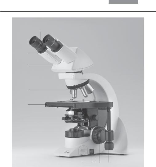
Fig. 2 Right side of the Leica DM1000 stand
1Eyepiece
2Eyepiece tube
3Tube
4Objective turret with objectives
5Specimen stage with specimen holder
6Integrated illumination
7On/Off switch
8Condenser height adjustment
9Coarse and fine focusing
10Coaxial pinion for x/y stage movement
13
5. Unpacking the Microscope
5.UnpackingtheMicroscope
First, carefully remove all components from the transportation and packaging materials.
Note:
If at all possible, avoid touching the lens surfaces of the objectives. If fingerprints do appear on the glass surfaces, remove them with a soft leather or linen cloth. Even small traces of finger perspiration can damage the surfaces in a short time. See the chapter "Care of the Microscope" → p. 54, for additional instructions.
Caution!
Do not yet connect the microscope and peripherals to the power supply at this point!
Installation Location
Work with the microscope should be performed in a dust-free room, which is free of oil vapors and other chemical vapors, as well as extreme humidity. At the workplace, large temperature fluctuations, direct sunlight and vibrations should be avoided. These conditions can distort measurements and micrographic images.
Allowable ambient conditions
Temperature |
15-35°C |
Relative humidity |
maximum 80% up to 30°C |
Microscopes in warm and warm-damp climatic zones require special care in order to prevent the build up of fungus.
See the chapter "Care of the Microscope" → p. 54, for additional instructions.
Caution!
Electrical components must be placed at least 10 cm away from the wall and away from flammable substances.
14

5. Unpacking the Microscope
Transport
For shipping or transporting the microscope and its accessory components, the original packaging should be used.
As a precaution to prevent damage from vibrations, the following components should be disassembled and packaged separately:
•Unscrew the objectives.
•Remove the condenser.
•Remove the coaxial pinion.
•Remove the lamp housings.
•Disassemble the burner of 106 z lamp housing.
•Remove all moving or loose parts.
15
6. Assembly
6.AssemblingtheMicroscope
The microscope components are logically assembled in this order:
•Stage
•Condenser
•Fluorescence*
•Intermediate systems*
•Tube
•Eyepieces
•Objectives
•Lamp housings with light sources
•Polarization*
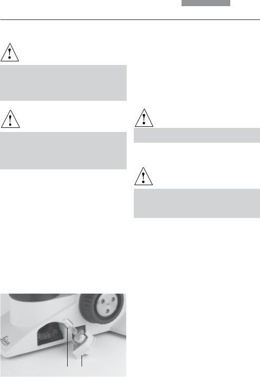
Only one commonly used screwdriver is necessary for assembly, which is included in the delivery package.
The tool can be stored on a magnetic retainer on the underside of the stage at the right.
When using intermediate systems and optical accessories, the sequence may vary.
In this case, read Chapter
"6.9 Optional Accessories" → p. 25.
6.1Stage
!Caution:
Before completing the stage, make sure no objectives are installed!
Specimen Holder
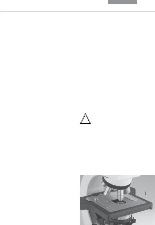
•Place the specimen holder on the stage and fasten it with the two screws (3.1).
Coaxial Pinion
Note:
The coaxial pinion can be mounted on the leftor right-hand side.
Fig. 3 Specimen stage with specimen holder 1 Lock screws for specimen holder
1
16
6. Assembly
•First, place the fine focus wheel on the side to which you intend to mount the coaxial pinion. The wheel is held in place magnetically (4.1). Ensure that the button snaps into place. Attach the other focus knob on the opposite side.
•Loosen the lock screw (5.1) at the front lefthand side of the stage.
•Slide the stage as far back as possible.
•Attach the coaxial pinion with the screw (6.1).
•Pull the stage forward and retighten the lock screw.
Fig. 5 Underside of stage 1 Lock screw
1
Fig. 4 |
Focus wheel |
Fig. 6 |
Coaxial pinion installation |
1 Magnetic retainer for fine focus wheel |
1 Mounting screw for coaxial pinion |
||
1 |
1 |
17

6. Assembly
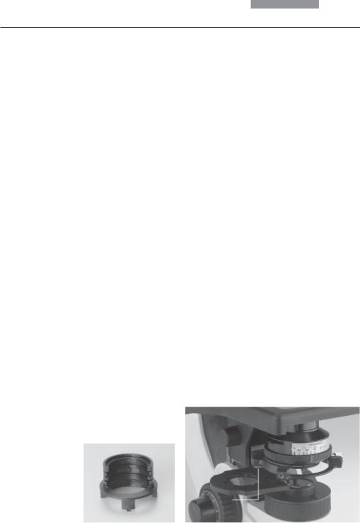
6.2 Condenser
•If present, screw the condenser head into the condenser.
•Using the condenser height adjuster (9.3), turn the condenser holder (fig. 8) completely downward.
•Unscrew the clamping screw for the condenser (9.2) far enough so that the condenser can be inserted from the front.
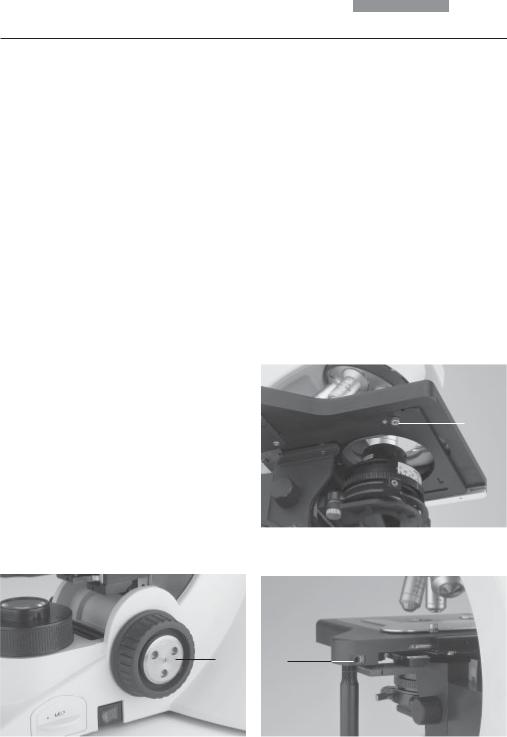
•From the front, insert the condenser into the condenser holder as far as it will go. On the underside of the condenser, there is an orientation pin (7.1), which must be located in the guiding notch (8.1).
•Pull the condenser’s clamping screw (9.2) so that the condenser is locked in place.
Note:
The condenser must be centered before using the microscope.
→ Köhler illumination p. 28.
Fig. 8 Condenser holder 1 Guiding notch
1
Fig. 9 Condenser holder 1 Condenser centering
2 Clamping screw for condenser
3 Condenser height adjuster
Fig. 7 Underside of condenser(example CL/PH)
1Orientation pin
2Auxiliary condenser lens LS
1 |
1 |
3 |
|
|
|
|
|
|
3 |
|
|
|
|
|
|
||||
1 |
|
|
|
|
|
2 |
||
|
|
|
|
|||||
|
|
|
||||||
|
|
|
|
|
|
|
|
1 |
|
|
|
|
|
|
|
||
2
18
6. Assembly
6.3 Tube and Eyepieces
Note:
For fluorescence applications, install the fluorescence illuminator first → p. 21.
If available, the analyzer* (10.1) must be inserted into the stand. This requires that the guide key engages in the guide pin (10.2).
To mount the analyzer, the analyzer mount TL* 20 mm or 60 mm can also be placed between stand and tube.
An intermediate tube pole* with a switchable analyzer (on/off) and Bertrand lens is also available as an option.
The tube is mounted to the stand either directly or with the use of intermediate modules.
Fig. 10 Analyzer mounting
1Analyzer
2Orientation pin and guiding notch
3Clamping screw
•Loosen the clamping screw (11.1) on the stand.
•Insert the tube in the circular receptacle (dovetail ring).
•Retighten the clamping screw (11.1).
•The eyepieces are inserted into the eyepiece tubes on the tube.
6.4 Objectives
Always only use Leica objectives of tube length × (infinity)! The standard thread is M25. The objectives should be arranged so that the magnification increases when the objective nosepiece is rotated counter clockwise.
!Attention:
Lower the specimen stage as far as possible before assembling the objectives. Close vacant threads in the nosepiece with dust protection caps!
Fig. 11 Fastening the tube 1 Clamping screw
1
19
6. Assembly
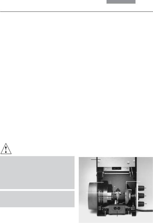
6.5 Light Source for the Transmitted Light Axis
Caution!
Be sure that the lamp housing is disconnected from the power supply. Unplug the power plug and the power supply during assembly.
Caution!
Light sources pose a potential irradiation risk (glare, UV-radiation, IR-radiation). Therefore, lamps have to be operated in closed housings.
Replacing the Lamp of the Integrated
Illumination
The transmitted light illumination with a lowvoltage tungsten halogen lamp (Fig. 12) is integrated in the base of the microscope and is accessible from the right-hand side.
• Remove the insert (12.2).
Caution!
The lamp may still be hot!
• Remove the lamp.
Caution!
Do not remove the new lamp’s dust cover until you have installed the lamp. Avoid fingerprints on the lamp.
•Insert the new lamp with the dust cover straight into the socket until it stops. Be sure that the lamp is inserted straight.
• Remove the lamp’s dust cover.
Fig. 12 Transmitted-light illumination in microscope base
1 |
Tungsten halogen lamp |
• Replace the insert (12.2). |
2 |
Insert |
|
1 2
20
6. Assembly
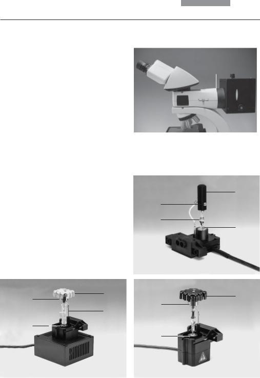
6.6 Components for Fluorescence Applications
6.6.1 Fluorescence illuminator
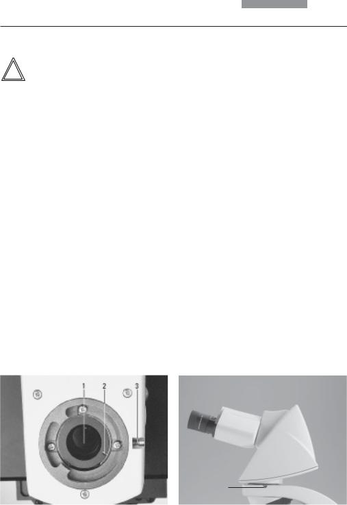
The fluorescence illuminator is mounted in front of the tube. It is fastened in place with the side clamping screw (13.1).
6.6.2 106 z Lamp Housing
Caution!
Light sources pose a potential irradiation risk (glare, UV-radiation, IR-radiation). Therefore, lamps have to be operated in closed housings.
During assembly, always unplug the power supply unit of the 106 z lamp housing from its socket.
During assembly work on xenon burners, always wear the supplied protective gloves and face protection (Fig. 14) (risk of explosion).
Never touch the glass parts of the burner with bare hands.
Never look directly into the beam path (blinding hazard).
This lamp housing is used with various gas discharge lamps.
Caution!
Make sure to follow the instructions and safety notes of the lamp supplier.
Before changing lamps allow at least 30 mins for cooling down!
Inserting the Ggas Discharge Lamps (Hg and Xe) into the 106z Lamp Housing
Hg and Xe lamps are powered by separate supply units.
Read the separate instruction manual provided with these supply units.
Fig. 13 Assembly of fluorescence illuminator 1 Clamping screw
1
Fig. 14
Protective gloves and mask
21
6. Assembly
The following gas discharge lamps may be used and require different supply units and lamp mounts (Fig. 16):
Type |
Typical Bulb Life* |
|
|
50 W high-pressure mercury burner (alternating current) |
100 hours. |
100 W high-pressure mercury burner (direct current) |
200 hours. |
100 W high-pressure mercury burner (direct current, type 103 W/2) |
300 hours. |
75 W high-pressure xenon burner (direct current) |
400 hours. |
* Please regard the data sheets for the burners. |
|
•To open the 106 z lamp housing, unscrew the fastening screws (15.8) on the cover.
•Remove the transport anchorage (red plastic rod in place of the burner) in the lamp mount. To do so, remove the lower clamp (16.1). Pull up the cooling element (16.3) and turn it to the side. Detach the lower clamp system (16.2) and remove the transport anchorage.
•Install the burner in reverse order.
Caution!
Hg 50 Burner:
After installation, the labeling must be upright. If a glass melt nipple is present (16a.4), position it by turning the burner so that the nipple does not come in the way of the beam path later, but instead is positioned sideways.
Xe 75 Burner:
Remove the burner’s dust cover (16b.5) after you have installed the burner.
Fig. 15 106 z lamp housing (on the side, open)
1Cover raised
2Collector
3Gas discharge lamp in mount
4Reflector (mirror)
5, 6, 7 Adjusting screw for x-y reflector
8Fastening screw for lamp mount
9Socket for contact plug
1
2 |
4 |
5
3
6
7
8 9 8
22
6. Assembly
•Insert the lamp mount, with the burner installed, into the lamp housing and tighten it with the screws (15.8).
•Close the lamp housing and retighten the screws.
•Place the lamp housing in the incident light lamp housing receptacle (17.1) and fasten it with the clamping screw on the side.
•Connect the lamp housing to the external power supply.
Fig. 16 a-c Lamp mounts for gas discharge lamps
1Upper clamping system
2Lower clamping system
3Cooling element
4Nipple of the mercury 50 burner,
5Dust cover of the mercury 75 burner
Xe 75 b
3
1
5
2
Fig. 17 Mounting the 106 z lamp housing 1 Lamp housing receptacle
1
Hg 50 a
3
1
4
2
Hg 100 c
3
1
2
23
6. Assembly
6.7 Analyzer and Polarizer*
Analyzer
If the analyzer was inserted into the tube mount before the tube assembly: (→ p. 19), no additional assembly step is required.
If an intermediate tube pole* or analyzer mount TL* is used:
• Remove the plug cap on the left side.
Alternative:
•Attach the polarizer holder to the underside of the condenser holder with the left clamp screw (19.1). Remove the flip-out blue filter if required.
•Push the polarizer with the labeled side upward into the lower opening.
•Insert the analyzer into the receptacle until it latches in place.
Polarizer
•Raise the condenser to its upper stop position.
•Remove the DLF filter magazine from the base if present.
•Press the polarizer holder in place (Fig. 18).
•Push the polarizer with the labeled side upward into the lower opening.
6.8 Lambda Plate Compensator*
•Raise the condenser to its upper stop position.
•Remove the DLF filter magazine from the base if present.
•Attach the lambda plate compensator to the base.
Fig. 19 Assembly of polarizer holder 1 Clamping screw
Fig. 18 Filter holder with 2 positions
1
24

6. Assembly
6.9 Optional Accessories
Camera
A camera can be connected via an adapter.
•Attach the adapter to the top port of the tube and fasten it tightly with the side clamping screw.
•Screw on the camera.
Note:
The size of the camera chip and the mounting system (B-mount, C-mount, etc.) must be considered when choosing an adapter.
See table.
Calculation of the magnification on the monitor The magnification MTV on the monitor can be calculated with the following formula or measured with a stage micrometer and a cm scale:
MTV = Objective magnification x
factor of magnification changer*x TV adapter magnification x monitor diameter
chip diameter of camera
|
Recorded picture diagonal in mm for |
|||
|
1 inch |
2/3 inch |
1/2 inch |
1/3 inch |
|
camera |
camera |
camera |
camera |
|
|
|
|
|
Without Zoom Magnification, Only for 1-Chip-Cameras: |
|
|
|
|
C-mount adapter 1 x HC |
16 |
11 |
8 |
6 |
C-mount adapter 0.63 x HC |
- |
17.5 |
12.7 |
9.5 |
C-mount adapter 0.5 x HC |
- |
- |
16 |
12 |
C-mount adapter 0.35 x HC |
- |
- |
- |
17.1 |
With Zoom Magnification (Vario TV Adapter) for 1-3 Chip-Cameras:
C-mount, 0.32-1.6 x HC |
- |
- |
19+)-5 |
18-3.8 |
B-mount (ENG), 0.5-2.4 x HC (1/2-inch) |
- |
- |
16-3.3 |
- |
+) from zoom factor 0.42 x only! |
|
|
|
|
Without Zoom Magnification, for 1-3 Chip-Cameras: |
|
|
|
|
C-mount adapter 1 x |
- |
- |
16 |
12 |
B-mount adapter 1 x |
- |
- |
16 |
12 |
B-mount adapter 1.25 x |
- |
17.5 |
- |
- |
F-mount adapter 1 x |
- |
- |
16 |
12 |
F-mount adapter 1.25 x |
- |
17.5 |
- |
- |
Plus (essential requirement): TV optics 0.5 x HC |
|
|
|
|
25
6. Assembly
Ergomodule
For raising the eye level of the tube opening, the 30 mm or 60 mm ergomodule may be used.
It is fastened in place with the side clamping screw.
Ergolift
A base for the stand featuring adjuster wheels for the base’s height and angle is available to ensure an optimal working position.
Magnification Changer
Optionally, a magnification changer (fig. 20) can be used, which is manually operated. On the knurled ring, the following magnification factors can be set:
Viewing Attachments
Viewing attachments featuring illuminated pointers are available for groups of up to 20 viewers.
The support (21.3) must be aligned precisely. The fade-in arrow can be moved in x and y direction (move the lever vertically or pull out/ push in) (21.1) If this lever is rotated, the color of the arrow can be changed (red/yellow). Use the brightness control (21.2) to adjust the brightness of the arrow.
1x; 1.5x; 2x
Fig. 21 Viewing attachment
1 |
Movement of light |
|
pointer in x and y direction, |
|||
|
and switchover of color filter |
|||||
2 |
Brightness control |
|
|
|
|
|
3 |
Adjustment of arm support |
|||||
The external power supply (illuminated arrow) is not |
||||||
illustrated. |
|
|
|
|
||
|
1 |
2 |
|
|
||
Fig. 20 Magnification |
|
|
|
|
|
|
|
|
|
|
|
|
|
changer |
|
|
|
|
|
|
|
|
|
|
|
|
|
|
|
|
3 |
|
|
|
|
|
|
|
|
||
26
6. Assembly
Tracing Device
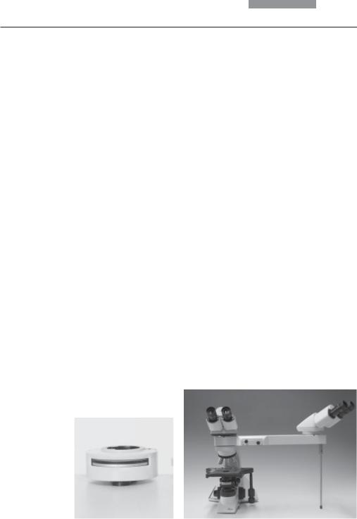
The tracing device L3/20 (fig. 22) allows an optical overlay of large objects (next to the microscope) on the microscope image. This makes it easy to draw specimens by tracing their outlines or superimposing scales.
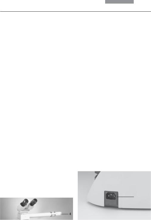
6.10 Connection to the Power Supply
•After completing the assembly work, connect the stand to the power supply using the power cable supplied (fig. 23).
•When using the lamp housing or the external power supply unit, connect them to the power supply, too.
Fig. 23 Back of the stand
1 Power supply connection
Fig. 22 Tracing device 1 Shutter
1
1
27
7. Start-up
7.Start-up
7.1 Switching on the Microscope
•Switch on the microscope with the on/off switch (24.1).
Caution!
After turning on the gas discharge lamp, the burner must be immediately adjusted. Therefore, do not turn on the power supply unit yet. First, work in transmitted light in order to familiarize yourself with the microscope’s controls.
7.2 Köhler Illumination
The condenser is also pre-adjusted in the factory.
However, it may be necessary to re-adjust the condenser in some cases. Therefore, check the condenser centering.
The following procedure is provided for the transmitted light brightfield illumination.
•If present click the condenser disk* into the BF position.
•If present pull the light ring slide* out of the condenser.
Fig. 24
1On/Off switch
2Focus wheel
3Stage positioning
•Select an objective with moderate magnification (10x-20x).
For condensers with movable condenser heads:
Swing in the condenser top.
(The condenser top is swung out for objective magnifications < 10x.)
•Insert the specimen into the stage’s specimen holder.
•Focus on the specimen using the focus wheel (24.2).
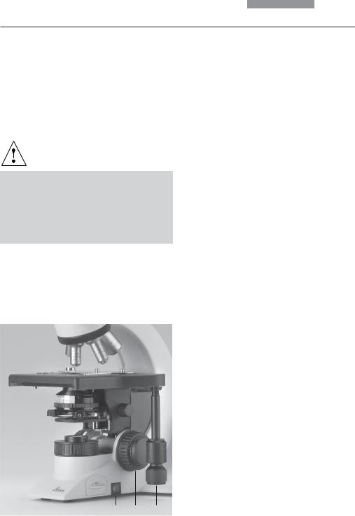
•Set the light intensity using the brightness control (25.2).
•Close the field diaphragm (25.3) until the edge of the diaphragm appears in the specimen plane (26a).
1 |
2 |
3 |
28
7. Start-up
•Using the condenser height adjuster (25.1), adjust the condenser until the edge of the field diaphragm appears in sharp relief(26b).
•If the image does not appear in the middle of the field of view (26c), the condenser must be moved into the middle of the field of view with the help of the two centering bolts (25.4). The tool required for this purpose is magnetically attached to the underside of the stage.
•Open the field diaphragm just enough for it to disappear from the field of view (26d).
Note:
The condenser height adjustment depends on the thickness of the specimen. It may be adjusted for different specimens.
Fig. 25
1Condenser height adjuster
2Brightness control
3Field diaphragm
4Condenser centering
7.3 Checking Phase Contrast Rings
If your microscope is equipped for the use of phase contrast, the light rings that fit the objectives are built into the condenser.
The light rings are already centered in the factory. However, the centering should be rechecked.
Note:
A light ring slide which is inserted into the side of the condenser is used for condensers without condenser disks. Centering is not required in this case.
Note:
When swivelling in a suitable objective for phase contrast, the corresponding light ring must be chosen.
The objective engraving (e.g. PH 1) indicates the corresponding light ring (e.g. 1).
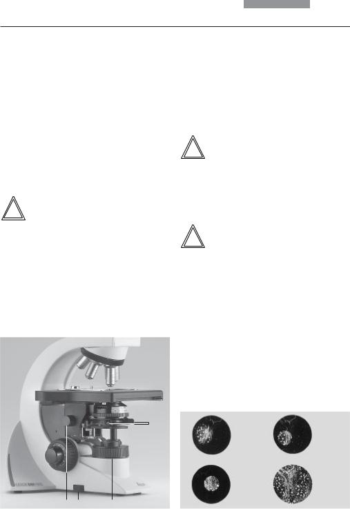
Fig. 26 Köhler Illumination
aField diaphragm not focused, not centered
bField diaphragm focused, but not centered
cField diaphragm
Diameter is too small, however
dField diameter (light) = Field diameter (view) (Köhler Illumination)
4
a |
b |
|
c |
d |
1 |
2 |
3 |
29
7. Start-up
•In the place of an eyepiece, insert the focusing telescope (Fig. 27) into the observation tube.
•Swivel in the phase contrast objective with the lowest magnification.
•Focus on the specimen with the focus wheel.
•Focus the ring structure (29.a) by slightly loosening the clamping ring (27.2) and moving the eye lens (27.1).
•Turn the centering screws until the dark ring (phase ring in the objective) is congruent with the slightly narrower bright ring (light ring in condenser) (29 c).
•Repeat the process for all other light rings.
•Remove the centering keys after the centering procedure.
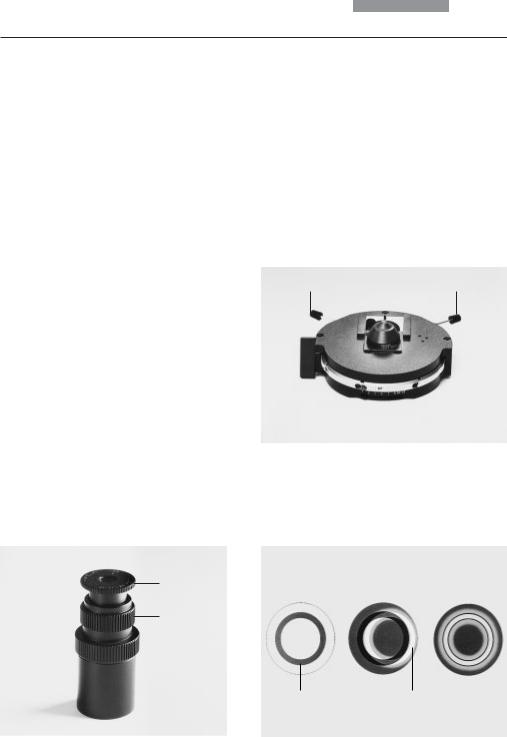
Fig. 28 Light ring centering (i.e.: condenser UCL/P) 1 Centering keys
• Retighten the clamping ring.
1 |
1 |
• Select the corresponding ring diaphragm (light ring) in the condenser.
•If the light ring and the phase ring are not shown as arranged in Fig. 29.c, the light ring must be centered.
•Insert the centering screws into the openings provided at the rear of the condenser (28.1).
|
|
Fig. 29 Phase contrast centering procedure |
|
|
PH=phase contrast ring, LR=light ring |
|
|
a Condenser in bright field (BF) position |
Fig. 27 Focusing telescope |
b Condenser in phase contrast (PH) position |
|
1 |
Adjustable eye lens |
Light ring (LR) not centered |
2 |
Clamping ring for fixing the focus position |
c Light ring and phase ring centered |
a |
b |
c |
1 |
|
|
2 |
|
|
PH |
LR |
30
 Loading...