


 Loading...
Leica CV5030
Robotic Coverslipper
Instructions for Use
Leica CV5030
Order No. 14 0478 80101 RevE
V 3.0, English - 04/2013
Always keep this manual with the instrument.
Read carefully before working with the instrument.

NOTE
The information, numerical data, notes and value judgments contained in this manual represent the current state of scientific knowledge and state-of-the-art technology as we understand it following thorough investigation in this field.
We are under no obligation to update the present manual periodically and on an ongoing basis according to the latest technical developments, nor to provide our customers with additional copies, updates etc. of this manual.
To the extent permitted in accordance with the national legal system as applicable in each individual case, we shall not be held liable for erroneous statements, drawings, technical illustrations etc. contained in this manual. In particular, no liability whatsoever is accepted for any financial loss or consequential damage caused by or related to compliance with statements or other information in this manual.
Statements, drawings, illustrations and other information regarding the contents or technical details of the present Instructions for Use are not to be considered warranted characteristics of our products.
Leica Biosystems Nussloch GmbH Heidelberger Str. 17 - 19
D-69226 Nussloch Germany
Phone: +49 6224 143-0
Fax: +49 6224 143-268
Internet: http://www.LeicaBiosystems.com
These are determined only by the contract provisions agreed between ourselves and our customers.
Leica reserves the right to change technical specifications as well as manufacturing processes without prior notice. Only in this way it is possible to continuously improve the technology and manufacturing techniques used in our products. This document is protected under copyright laws. All copyrights to this documentation are held by Leica Biosystems Nussloch GmbH.
Any reproduction of text and illustrations (or of any parts thereof) by means of print, photocopy, microfiche, web cam or other methods—includ- ing any electronic systems and media—requires express prior permission in writing by Leica Biosystems Nussloch GmbH.
For the instrument serial number and year of manufacture, please refer to the nameplate on the back of the instrument.
© Leica Biosystems Nussloch GmbH
Leica CV5030 – Robotic Coverslipper |
3 |

|
|
Contents |
|
|
|
|
|
1. |
Important Information..................................................................................................... |
7 |
|
|
1.1 |
Symbols and their meanings....................................................................................................... |
7 |
|
1.2 |
User group...................................................................................................................................... |
9 |
|
1.3 |
Intended use of instrument.......................................................................................................... |
9 |
|
1.4 |
Instrument type.............................................................................................................................. |
9 |
2. |
Safety............................................................................................................................... |
10 |
|
|
2.1 |
Safety notes................................................................................................................................. |
10 |
|
2.2 |
Warnings...................................................................................................................................... |
10 |
3. |
Instrument Components and Specifications............................................................ |
13 |
|
|
3.1 |
Overview - instrument components......................................................................................... |
13 |
|
3.2 |
Technical data............................................................................................................................. |
14 |
|
3.3 |
Standard delivery—packing list............................................................................................... |
15 |
4. |
Instrument Setup........................................................................................................... |
17 |
|
|
4.1 |
Installation site requirements................................................................................................... |
17 |
|
4.2 |
Unpacking the CV5030................................................................................................................ |
18 |
|
4.2.1 |
Setting up the CV5030................................................................................................................. |
20 |
|
4.3 |
Preparing and adjusting the instrument.................................................................................. |
20 |
|
4.3.1 |
Removing or installing the transport anchors........................................................................ |
21 |
|
4.4 |
Leveling the instrument.............................................................................................................. |
22 |
|
4.5 |
Exhaust system............................................................................................................................ |
22 |
|
4.6 |
Installing the dispenser group.................................................................................................. |
24 |
|
4.7 |
Aligning the dispenser needle height relative to the specimen slide outfeed.................. |
26 |
|
4.8 |
Dispenser needle cleaner (nozzle cleaner)............................................................................ |
29 |
|
4.9 |
Connecting the power supply................................................................................................... |
32 |
|
4.10 |
Installing the accessories.......................................................................................................... |
32 |
|
4.11 |
Refilling consumables................................................................................................................ |
34 |
5. |
Operation........................................................................................................................ |
36 |
|
|
5.1 |
Control panel functions.............................................................................................................. |
36 |
|
5.2 |
Key functions for instrument operation................................................................................... |
37 |
|
5.3 |
Switching the instrument on or off........................................................................................... |
39 |
|
5.4 |
Brief inspection before starting the coverslipping operation.............................................. |
41 |
|
5.5 |
The coverslipping operation...................................................................................................... |
42 |
|
5.6 |
Interrupting the coverslipping operation................................................................................ |
44 |
|
5.7 |
Display indicators and instructions.......................................................................................... |
50 |
|
5.8 |
Button functions for programming........................................................................................... |
56 |
4 |
Instructions for Use V 3.0 RevE – 04/2013 |

Contents
|
5.9 |
Setting parameter sets............................................................................................................... |
57 |
|
5.10 |
Menu A – parameter settings................................................................................................... |
57 |
|
5.11 |
Menu B – parameter settings................................................................................................... |
60 |
|
5.11.1 |
Leaving the parameter and submenu...................................................................................... |
62 |
|
5.12 |
Recommendation for parameter setting (beginning with firmware 3.01.04) .................... |
63 |
|
5.13 |
Determining the optimum parameter setting (menu A+B)................................................... |
66 |
|
5.13.1 Procedure..................................................................................................................................... |
66 |
|
6. |
Workstation operation................................................................................................. |
72 |
|
|
6.1 |
Operation as ST5010 – CV5030 workstation............................................................................ |
72 |
|
6.2 |
Operation as ST5020 – CV5030 workstation............................................................................ |
74 |
|
6.3 |
Important instructions for operation as workstation............................................................ |
76 |
|
6.4 |
Interrupting workstation operation.......................................................................................... |
78 |
7. |
Cleaning and Maintenance......................................................................................... |
79 |
|
|
7.1 |
Notes on cleaning and maintenance....................................................................................... |
79 |
|
7.2 |
Daily cleaning and maintenance - overview.......................................................................... |
80 |
|
7.3 |
Weekly cleaning and maintenance.......................................................................................... |
81 |
|
7.4 |
Cleaning and maintenance as necessary............................................................................... |
82 |
|
7.5 |
Description of the required daily cleaning measures........................................................... |
82 |
|
7.5.1 |
Loading chute and bath transport with transport chain....................................................... |
82 |
|
7.5.2 |
Dispenser needle cleaner (nozzle cleaner)............................................................................ |
82 |
|
7.5.3 |
Glass vial in the dispenser rest position.................................................................................. |
83 |
|
7.5.4 |
Loading bath................................................................................................................................. |
83 |
|
7.5.5 |
Dispenser needles...................................................................................................................... |
83 |
|
7.5.6 |
Cover slip catch tray................................................................................................................... |
83 |
|
7.5.7 |
Cover slip magazine.................................................................................................................... |
83 |
|
7.5.8 |
Skids of the Pick & Place module............................................................................................. |
83 |
|
7.5.9 |
Cleaning and replacing the suction cups................................................................................ |
84 |
|
7.5.10 |
Cover slip sensor......................................................................................................................... |
84 |
|
7.5.11 |
Specimen slide outfeed.............................................................................................................. |
84 |
|
7.6 |
Description of the required weekly cleaning measures....................................................... |
85 |
|
7.6.1 |
Dispenser group.......................................................................................................................... |
85 |
|
7.6.2 |
Dispenser needle cleaner (nozzle cleaner)............................................................................ |
86 |
|
7.6.3 |
Specimen slide holder, gripper and output magazines........................................................ |
86 |
|
7.7 |
Description for cleaning and maintenance as necessary................................................... |
87 |
|
7.7.1 |
Active carbon filter..................................................................................................................... |
87 |
|
7.7.2 |
Discharge chute of the TS5015 or TS5025 Transfer Station for workstation operation...... |
87 |
Leica CV5030 – Robotic Coverslipper |
5 |

Contents
|
7.7.3 |
Transfer arm of the TS5015 or TS5025 Transfer Station for workstation operation......... |
87 |
|
7.8 |
Procedure for changing the cover slip mountant.................................................................. |
88 |
|
7.8.1 |
Changing from one xylene-based coverslip mountant to another...................................... |
88 |
|
7.8.2 |
Changing from a xylene substitute coverslip mountant to a xylene-based mountant.... |
88 |
|
7.8.3 |
Changing from a xylene-based coverslip mountant to a xylene substitute...................... |
88 |
8. |
Malfunctions and Troubleshooting............................................................................ |
89 |
|
|
8.1 |
Error codes................................................................................................................................... |
89 |
|
8.2 |
Troubleshooting........................................................................................................................... |
91 |
9. |
Optional Accessories................................................................................................... |
95 |
|
|
9.1 |
Ordering information................................................................................................................... |
95 |
10. |
Warranty and Service................................................................................................. |
106 |
|
Appendix A Application-related notes and recommendations............................... |
107 |
||
|
A1.1 |
Leica specimen slide holders, output and coverslip magazines made of plastic.......... |
107 |
|
A1.2 |
Specimen slide holders from other manufacturers............................................................. |
108 |
|
A1.3 |
Specimen slides and gripper mechanism............................................................................. |
109 |
|
A1.4 |
CV5030 – Validated and recommended specimen slides................................................... |
109 |
|
A1.5 |
Cover slips.................................................................................................................................. |
111 |
|
A1.6 |
Labels for specimen slides...................................................................................................... |
112 |
6 |
Instructions for Use V 3.0 RevE – 04/2013 |

1. Important Information
1.1Symbols and their meanings
Warnings
appear in a gray box and are marked by a warning triangle  .
.
Notes
i.e. important user information appear in a gray box and are marked by an in-
formation symbol  .
.
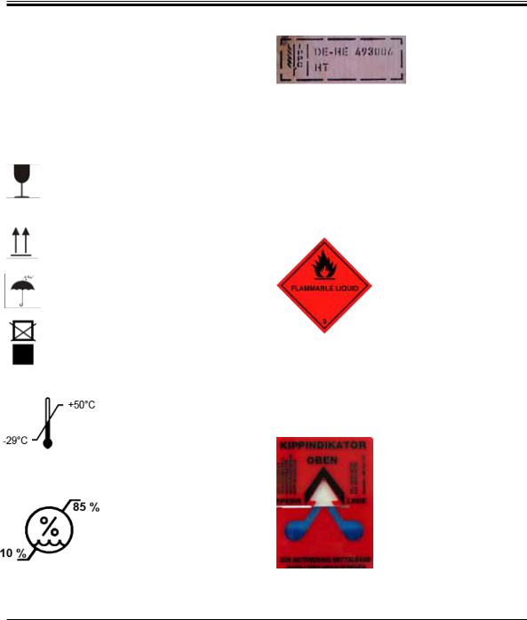
Inflammable solvent and reagents are marked with this symbol.
Instrument surfaces which become hot during operation are marked with this symbol.
Avoid direct contact to prevent risk of burning.
(5)Numbers and parentheses refer to item numbers in the illustrations.
Function keys to be pressed on the in- START strument control panel are written in
bold-print capital letters.
Manufacturer
 In vitro diagnostics (IVD) medical device
This product fulfills the requirements of the Council's Directive 98/79/EC concerning in vitro diagnostics (IVD) medical devices.
The CSA test mark means that a product has been tested and fulfills the applicable safety and/or performance standards, including the relevant standards defined or administered by the American National Standards Institute (ANSI), Underwriters Laboratories (UL), the Canadian Standards Association (CSA), the National Sanitation Foundation International (NSF) and others.
Environmental protection symbol of the China RoHS directive. The number in the symbol indicates the "Environmentfriendly Use Period" of the product. The symbol is used if a substance restricted in China is used in excess of the maximum permitted limit.
Symbol for labeling electrical and electronic equipment in accordance with Section 7 of the German Electrical and Electronic Equipment Act (ElektroG). ElektroG is the law regarding the sale, return and environmentally sound disposal of electrical and electronic equipment.
Leica CV5030 – Robotic Coverslipper |
7 |
1.Important Information
1.1 Symbols and their meanings REF Order No.
SN Serial number
Observe the Instructions for Use
The package contents are fragile and must be handled with care.
Indicates the correct upright position of the package.
The package must be kept in a dry environment.
It is not permitted to stack packages, and no loads may be placed on top of the package.
Indicates the temperature range to which the medical device can be safely exposed.
Minimum –29 °C Maximum +50 °C
Indicates the air humidity range to which the medical can be safely exposed.
Minimum 10 %
Maximum 85 %
Example of labeling in accordance with IPPC
•IPPC symbol
•Country code in accordance with ISO 3166, e.g. DE for Germany
•Regional identifier, e.g. HE for Hessen
•Producer/treatment provider code, unique assigned number starting with 49
•Treatment code, e.g. HT (heat treatment), MB
(methyl bromide), and possibly DB (debarked)
Package labeling in accordance with German Hazardous Freight Ordinance Road and Rail (GGVSE)/European Agreement concerning the International Carriage of Dangerous Goods by Road (ADR) for transporting hazardous goods.
Class 3: "FLAMMABLE LIQUID"
Tip-n-Tell checks whether the shipment was transported upright and stored as you prescribed. With a pitch of 60° or more, the blue quartz sand flows into the arrowshaped indicator window and sticks there permanently. Any improper handling of the shipment is immediately and definitively detectable.
8 |
Instructions for Use V 3.0 RevE – 04/2013 |
1. Important Information
1.2User group
•The Leica CV5030 may be operated by trained laboratory personnel only.
•Alllaboratorypersonneldesignatedtooperate this instrument must read these Instructions for Use carefully and must be familiar with all technical features of the instrument before attempting to operate it.
1.3Intended use of instrument
The Leica CV5030 is a robotic coverslipper for coverslipping tissue sections, cells or swabs mounted on specimen slides with cover slips made out of glass using a wide variety of different cover slip mountants. It may only be used with instrument accessories approved by Leica Biosystems Nussloch GmbH.
Any use of the instrument other than its designated use is considered improper.
Failure to adhere to these instructions may result in an accident, personal injury, damage to the instrument or accessory equipment.
Proper and intended use includes compliance with all inspection and maintenance instructions, along with the observance of all instructions in the Instructions for Use.
1.4Instrument type
All information provided in these Instructions for Use applies only to the instrument type indicated on the cover page.
A nameplate indicating the instrument serial number is attached to the rear side of the instrument. (The serial number is also displayed above the loading door on the front side of the instrument.)
Fig. 1
Fig. 1 is provided as an example only and shows a valid nameplate for this instrument with the necessary information about instrument type and power requirement. The precise data for the various versions is specified in Chapter 3.2 "Technical data".
Leica CV5030 – Robotic Coverslipper |
9 |
2.Safety
2.1Safety notes
•The safety and caution notes in this chapter must be observed at all times.
•Be sure to read these notes even if you are already familiar with the operation and use of other Leica products.
•The protective devices on the instrument and its accessories must not be removed or modified. Only qualified service personnel authorized by Leica may repair the instrument and access its internal components.
Residual risks
•The instrument has been designed and constructed with the latest state-of-the-art technology and according to recognized standards and regulations with regard to safety technology. Operating or handling the instrument incorrectly can place the user or other personnel at risk of injury or can cause damage to the instrument or other property. The instrument may be used only as intended and only if all of its safety features are in proper working condition. Malfunctions which could impede safety must be remedied immediately.
•Only original spare parts and permitted original accessories may be used.
These Instructions for Use include important instructions and information related to the operating safety and maintenance of the instrument.
The Instructions for Use are an important part of the product, and must be read carefully prior to startup and use and must always be kept near the instrument.
This instrument was built and tested in accordance with the safety regulations for electrical measuring, control, regulating and laboratory devices.
To maintain this condition and ensure safe operation, the user must observe all notes and warnings contained in these Instructions for Use.
These Instructions for Use must be appropriately supplemented as required by the existing regulations on accident prevention and environmental safety in the operator's country.
The instrument's CE certificate can be found on the Internet at:
http://www.LeicaBiosystems.com
2.2Warnings
The safety devices installed in this instrument by the manufacturer only constitute the basis for accident prevention. Operating the instrument safely is, above all, the responsibility of the owner, as well as the designated personnel who operate, service or repair the instrument.
To ensure trouble-free operation of the instrument, make sure to comply with the following instructions and warnings.
Please note that electrostatic charge may result through direct or indirect contact with the Leica CV5030.
10 |
Instructions for Use V 3.0 RevE – 04/2013 |
2. Safety
2.2Warnings (continued)
Safety instructions - transport and installation
•The instrument must be transported in an upright position only (use transport anchors!).
•Two persons are required when lifting or carrying the instrument!
•The Leica CV5030 is intended for use in enclosed rooms only.
•The instrument may be operated with the provided power cable only. This power cable may not be replaced by another. Should the provided power cable not fit in the socket at the installation location, notify the responsible Leica Service.
•Only connect the instrument to a grounded power socket. The protective effect may not be eliminated by an extension cable without a protective grounding conductor. The instrument automatically recognizes the applied voltage/frequency.
•The installation location must be well ventilated, and must contain no sources of ignition of any kind. The chemicals to be used in the Leica CV5030 are highly flammable as well as hazardous to health.
•The instrument may not be operated in hazardous locations.
•Condensation water may form in the instrument if there is an extreme difference in temperature between the warehouse and the installation site and if air humidity is high at the same time. If this is the case, wait at least two hours before switching on the instrument. Failure to comply with this may cause damage to the instrument.
•The instrument must be leveled carefully before commissioning (for more information, refer to Chapter 4.5, "Instrument Setup").
Safety instructions - working with the instrument
•The instrument may only be operated by trained laboratory personnel.
•It must only be operated for the purpose of its designated use and according to the instructions contained in these Instructions for Use.
•In the event of an emergency, switch off the power switch and unplug the instrument from the power supply.
•Suitable protective clothing (lab coat, gloves, protective goggles) must be worn when working with reagents. Avoid skin contact with solvents or cover slip mountants.
•Make sure that mountant is applied in the correct amount (for additional information, refer to Chapter 5.10 - Menu A - Parameter settings). Excess mountant can run from the specimen slide onto the work surface and the transport belt of the bath insert, thus impairing the movement of parts of the instrument (refer also to Chapter 7 - Cleaning and Maintenance).
•During operation, do not block motor-driven components with objects or manual interference. There is a risk of injury from broken glass!
•Do not carry out the discarding movement of the Pick & Place module (cover slip mount) manually! Please observe the notes in Chapter 4.7.1.
•Never leave the instrument unattended for a long period of time. Particular care must be taken during a power failure to ensure that tissue sections do not dry out.
•Remove all glass parts or other objects away from the CV5030 working area during STOP. Only then may START be actuated.
Leica CV5030 – Robotic Coverslipper |
11 |
2.Safety
Safety instructions - working with the instrument (continued)
•Operate the instrument with the exhaust hose and connection on an external laboratory extraction or under a suitable fume hood. In the process, the corresponding active carbon filter should be used for auxiliary support.
•Since the instrument is intended to be operated with a solvent, there is a fire hazard if work with an exposed flame (e.g. Bunsen burner) is carried out in the direct vicinity of the instrument.
•Ensure that no liquids come into contact with the electronics during work.
Warnings - Handling reagents
•Take care when handling solvents and coverslip mountants!
•Always wear rubber gloves, a lab coat and safety goggles when handling the chemicals used in this instrument.
•The reagents used can be both toxic and/or flammable.
•Dispose of used reagents while observing applicable local regulations and the disposal regulations of your company/lab.
Hazards - servicing and cleaning
•Before each maintenance task, remove the loading bath and the specimen slide holder from the instrument, switch the instrument off and unplug it from the power supply.
•Only Leica service technicians are authorized to open the instrument for maintenance and repair work.
•When using cleaners, please comply with the safety instructions of the manufacturer and the laboratory safety regulations.
•When cleaning the instrument surfaces, do not use scouring powders or solvents containing acetone, chlorine or xylene.
•Clean the lid and the housing with mild and pH-neutral commercial household cleaners. Aggressive cleaning agents and solvents can damage the lacquered surfaces!
•Ensure that no liquids come into contact with the electronics during cleaning.
Material safety data sheets for reagents can be requested from the respective manufacturer of the chemical.
Alternatively, the material safety data sheets can be downloaded from the following website: http://www.msdsonline.com
12 |
Instructions for Use V 3.0 RevE – 04/2013 |
3. Instrument Components and Specifications
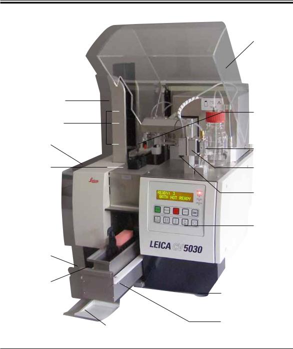
3.1Overview - instrument components
Output station for output magazines
Output magazines
Maintenance
door
Cover slip magazine
Main switch
Loading bath
Input door
Fig. 2
Unit cover
Pick & Place module (cover slip mount)
Bottle for coverslip mountant
Dispenser group
Dispenser rest (park) position (prime position)
Control panel
Height-adjustable instrument feet
Loading drawer
Leica CV5030 – Robotic Coverslipper |
13 |

3.Instrument Components and Specifications
3.2Technical data
Nominal supply voltages:
Nominal frequency:
Approvals
Fuse:
Nominal power:
Dimensions (W x H x D):
Width (from the left to the right base):
Depth (from the posterior base to the front base): Multistainer workstation:
Weight (without packaging material):
Net weight (including packaging material): Operating temperature range:
Storage temperature range: Transport temperature range: Relative humidity:
IEC 1010 classification:
International protection class: Operating elevation: A-weighted noise level: Sockets
Uninterruptible power supply (UPS):
Heat dissipation:
Exhaust air:
Hose material
Hose length:
Hose diameter:
Hose circumference:
Exhaust air quantity:
Extraction:
100 - 240 V AC, ± 10 %
50 - 60 Hz CE, CSA C/US
Automatic fuseT5A
100 VA
Hood closed: 420 x 600 x 550 mm Hood opened: 420 x 980 x 550 mm 370 mm
525 mm
Hood opened: 1620 x 980 x 760 mm approx. 57 kg
approx. 104 kg +15 °C - +35 °C –29 °C - +50 °C –29 °C - +50 °C
Maximum 85 % (non-condensing) Protection class 1
Pollution degree 2
Overvoltage installation category II IP20
Up to a max. of 2000 m above sea level <65 dB(A), measured in 1 m target range RS 232C, service interface
The uninterruptible power supply (UPS) should be designed for a capacity of at least 200 VA over a time frame of 5 minutes.
100 J/s
EVA (ethylene vinyl acetate) 3000 mm
32 mm
41 mm 38.5 m3/h
Active carbon filter and extraction hose for connecting to an external extraction device
14 |
Instructions for Use V 3.0 RevE – 04/2013 |

|
3. Instrument Components and Specifications |
|
|
3.2 Technical data (continued) |
|
Performance: |
|
Specimen slide throughput: |
1 specimen slide in approx. 9 sec. |
Usable specimen slides: |
All commercially available specimen slides per |
|
ISO standard 8037-1. Leica recommends the use of |
|
validated Surgipath™ specimen slides. |
Cover slip magazine capacity: |
Dependent on thickness of the cover slip: |
|
120 (22-24 mm x 60 mm; #1.5) |
|
160 pcs. (22-24 mm x 40 mm; #1.0) |
Cover slips: |
22-24 mm x 40 - 60 mm; #1.0 or #1.5 |
|
Leica recommends the use of validated Surgipath™ |
|
ASC cover slips or Surgipath™ Premier Cover |
|
Glass cover slips. |
Mountant bottle capacity: |
250 ml |
Max. fill volume: |
200 ml |
Coverslip mountant application quantity: |
Individually configurable |
Mountant types: |
See Chapter 5.12 |
Specimen slide holders: |
Leica specimen slide holders (20 or 30 specimen |
|
slides) and other specimen slide holders (refer to |
|
Chapter 9 - "Optional Accessories") |
Output magazines: |
Capacity of 20 or 30 specimen slides (up to |
|
60 specimen slides) |
3.3Standard delivery—packing list
The standard equipment for the Leica CV5030 includes the following parts: |
Order number |
|
1 |
Basic instrument |
14 0478 39700 |
1 |
Dispenser group, consisting of: |
14 0478 39402 |
|
1 Dispenser |
|
|
2 Dispenser needles, 21 G |
14 0478 40157 |
|
2 Dispenser needles, 20 G |
14 0478 40158 |
|
2 Dispenser needles, 18 G |
14 0478 40159 |
|
2 Dispenser needles, 16 G |
14 0478 40160 |
Leica CV5030 – Robotic Coverslipper |
15 |

3.Instrument Components and Specifications
3.3Standard delivery—packing list (continued)
1 Accessory kit, consisting of: |
14 0478 39734 |
|
1 Leica brush |
14 0183 30751 |
|
1 |
Allen key, No. 3.0 |
14 0222 04138 |
1 |
Screwdriver 5.5 x 150 |
14 0170 10702 |
1 |
Set of power cables, consisting of: |
|
|
1 Power cable for UK ST/BU F-5A |
14 0411 27822 |
|
1 Power cable for Germany |
14 0411 13558 |
|
1 Power cable for USA/Canada/Japan |
14 0411 13559 |
|
1 Power cable for Brazil |
14 0411 47869 |
1 |
Active carbon filter (xylene) |
14 0422 30673 |
1 Dispenser needle cleaner, assembly |
14 0478 40941 |
|
2 |
Glass bottles with lids, for coverslip mountant, 250 ml |
14 0464 36537 |
1 |
Package of 5 pcs. of 30 specimen slide holder, plastic |
14 0475 33643 |
1 |
Cover for loading bath |
14 0478 39584 |
1 |
Cover slip catch tray |
14 0478 39585 |
1 Package of 4 pcs. of 30 output magazine |
14 0478 39586 |
|
1 |
Loading bath for specimen slide, deep |
14 0478 39657 |
1 |
Bath insert for Leica 30 specimen slide holder |
14 0478 39593 |
1 Package of 2 pcs. suction cups |
14 0478 39701 |
|
2 |
Cover slip magazines, Multi-size™ 40-60 x 22 mm |
14 0478 39748 |
2 |
Cover slip magazines, Multi-size™ 40-60 x 24 mm |
14 0478 39749 |
1 |
Glass vial, 12 ml |
14 0478 39789 |
1 Exhaust hose, 3 m |
14 0478 39820 |
|
1 Instructions for Use, English, for Leica CV5030 |
14 0478 80101 |
|
1 Language CD-ROM |
14 0478 80200 |
|
Carefully check the delivery against the packing list and the delivery note. Should you find any discrepancies, please contact your Leica sales office without delay.
16 |
Instructions for Use V 3.0 RevE – 04/2013 |

4. Instrument Setup
4.1Installation site requirements
The location for the Leica CV5030 Robotic Coverslipper must meet the following requirements:
•The installation location must be well ventilated, and must contain no sources of ignition of any kind.
•The chemicals used in the Leica CV5030 are easily inflammable and pose a health hazard.
•Never operate the instrument in rooms with an explosion hazard.
•Condensation water may form in the instrument if there is an extreme difference in temperature between the storage location and the installation site and if air humidity is high at the same time. If this is the case, wait at least two hours before switching on the instrument.
•Failure to adhere to this waiting period may result in damage to the instrument.
•To ensure proper function of the instrument, it must be set up while maintaining a minimum clearance of 10 cm between the right side or rear panel of the instrument and walls or fixtures. Maintain a clearance of 25 cm between the left side and walls or fixtures to ensure unimpeded access to the service door.
•The instrument must be set up so that the power supply at the rear panel of the instrument and the power plug can be reached at all times.
•The installation location must be protected against electrostatic discharges.
•The instrument requires an installation area of approx. 420 x 600 mm.
•The table must have a sufficient load capacity and rigidity with respect to the weight of the instrument.
•The instrument is designed for indoor use only.
•The power supply must be at a distance no greater than the length of the power cable; do not
connect an extension cable.
•The instrument MUST be connected to a grounded socket.
•Use only one of the provided power cables that is intended for the local power supply.
•The instrument must not be set up under an air-conditioning system.
•Avoid impacts, direct sunlight and excessive current fluctuations.
•The chemicals used in the instrument are easily inflammable and pose a health hazard.
•All of the device connections are listed in the Instructions for Use.
•We recommend operating the robotic coverslipper with an exhaust hose (max. length of the
exhaust hose: 3.00 m) and connection to external laboratory extraction or under a suitable fume hood. The instrument should be operated with the associated active carbon filter in the process.
Leica CV5030 – Robotic Coverslipper |
17 |

4.Instrument Setup
4.1Installation site requirements (continued)
•The instrument operator has to ensure that ESD safety precautions are maintained.
•The instrument operator is obligated to conform to the local workplace limit values and to document them.
Furthermore, the instrument operator must ensure that there is sufficient air exchange and the active carbon filter is changed at the recommended interval.
The instrument operator bears responsibility for complying with workplace limits and the measures necessary for this, including documentation.
4.2Unpacking the CV5030
|
|
|
When the instrument is delivered, check the tilt indicators on the pack- |
|
|
|
|
aging. If the arrowhead is blue, the shipment was transported laying |
|
|
|
|
flat, was tilted at too great an angle or fell over during transport. |
|
|
|
|
Note this on the shipping documents and check the shipment for |
|
|
|
|
possible damage. |
|
|
|
|
Only personnel authorized by Leica may unpack and install the instrument. |
|
|
|
2 |
|
Opening the package (Fig. A) |
|
|
|
• Unscrew the 8 screws (Fig. A, 2) on the sides |
|
|
|
|
|
|
|
|
|
|
of the wooden box and loosen the cover. |
|
4 |
|
|
• Carefully lift the cover from the wooden box. |
|
|
|
1 |
|
|
|
|
|
|
|
|
|
7 |
|
|
|
|
3 |
|
|
|
|
Fig. A |
|
18 |
|
|
|
Instructions for Use V 3.0 RevE – 04/2013 |

4. Instrument Setup
4.2Unpacking the CV5030 (continued)
7
6
5
Fig. B
Removing the accessories (Fig. B)
•Remove the two screws (Fig. A, 4) in the side panel (left and right) and take out the transport anchor (5).
•The box with accessories (6) can now be removed from the shipping package.
9
8
Removing the instrument
•Unscrew the 8 screws (Fig. A, 3) on the bottom of the wooden box on the exterior. Carefully remove the wooden box from the baseplate.
•Unscrew 2 x 4 screws (front and rear on the instrument, (8) in Fig. C), loosen and remove the retaining clips (9) from the baseplate.
•Remove the dust cover from the instrument.
For setting up the instrument, refer to Chapter 4 .2.1 - Setting up the CV5030.
9
Fig. C
Leica CV5030 – Robotic Coverslipper |
19 |

4. |
Instrument Setup |
|
|
|
|
4.2.1 Setting up the CV5030 |
|
|
|
|
• Grab hold of bottom of the instrument from |
|
|
|
|
|
the front and rear (with at least 2 people; the |
|
21 |
instrument weighs approx. 57 kg) and place it |
|
|
on a stable laboratory table. |
|
|
• When doing so, ensure that the instrument is |
|
|
standing on all four feet. |
|
|
• Pull the plastic protective hood off of the in- |
|
|
strument by pulling upwards and remove the |
|
|
two adhesive strips (20). |
|
|
• Remove the foam safeguard (21) from the |
|
|
output station. |
|
20 |
• Open the loading door (65) and remove the |
|
foam cover for the loading bath. |
|
65• Ensure that the provided accessories are complete in accordance with the order.
4.3Preparing and adjusting the instrument
To commission the instrument, carry out the following tasks described in the chapters below:
•Remove the transport anchors.
•Insert the filter and attach the exhaust hose.
•Level the instrument.
•Install the dispenser group.
•Align the dispenser needle with the specimen slide outfeed.
•Install the dispenser needle cleaner.
•Connect the power supply.
•Use the following accessories:
-Mountant bottle
-Cover slip catch tray
-Cover slip magazine
-Output magazine
-Loading bath
-Dispenser needle cleaner
-Glass vial for dispenser rest position
-Refill consumables
20 |
Instructions for Use V 3.0 RevE – 04/2013 |
4. Instrument Setup
4.3.1 Removing or installing the transport anchors
|
• Open the service door (28) on the left |
50 |
side of the instrument and remove the |
foam (50). |
28 |
Fig. 4 |
|
1.Remove the transport anchor (24) for the Pick & Place module.
2.Remove the transport anchor (25) for the gripper. The gripper slowly moves downward in the process.
•Using the provided No. 3 Allen key, unscrew the screws (22) and (23) for the two red transport anchors (24) and (25) (see Fig. 5):
24 |
Transport anchor (24) for |
|
|
|
the Pick & Place module |
23 |
24 |
|
|
|
|
22 |
Transport anchor for the |
|
|
gripper (25) |
|
|
|
|
|
25 |
|
23 |
|
|
|
|
|
|
|
25 |
|
|
|
|
|
|
|
Fig. 5
• To transport the instrument, reinstall the transport anchors in the opposite order.
We recommend keeping the transport anchors and screws close to the instrument in the provided clear plastic bag.
Leica CV5030 – Robotic Coverslipper |
21 |

4.Instrument Setup
4.4Leveling the instrument
Detail 2
Fig. 6
•Movetheinstrumenttoitsfinallocationonthe work surface.
When doing so, ensure that all four feet are on the work surface.
26
•Openthehoodandplaceasuitablespiritlevel
(26) onto the work surface as shown in Fig. 6.
27
•The instrument can be leveled in both directions by screwing or unscrewing the instrument feet (27) (detail 2 in Fig. 6).
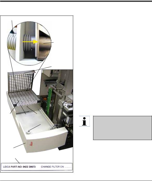
4.5Exhaust system
We recommend operating the robotic coverslipper with an exhaust hose and connection to external laboratory extraction or under a suitable fume hood. The associated active carbon filter is intended to be used in a supporting role for this. We recommend replacing the active carbon filter every three months. Please note that the active carbon filter, when used alone, can filter only a limited number of harmful vapors (e.g. xylene). The setup location can differ substantially in terms of solvent loading, room ventilation, room/ambient temperature, room size, etc.
In case of doubt, the laboratory owner/operator must have measurements conducted on site to ensure that the legal limits for solvent vapors are not being exceeded.
22 |
Instructions for Use V 3.0 RevE – 04/2013 |
4. Instrument Setup
4.5Exhaust system (continued)
70 |
Detail: |
|
|
|
33 |
|
|
30 |
32 |
31 |
29 |
|
|
|
|
|
34 |
28 |
|
|
31 |
Filter label |
|
|
||
|
|
Fig. 7 |
Inserting the active carbon filter
•Unscrew the slotted screw (34) at the service door (28) on the left side of the instrument and open the service door to the left (Fig. 7).
•Unscrew the screw (29) of the filter cover (30) using a No. 3 Allen key and pivot the cover upwards.
•The insertion date can be written down on the adhesive label (31).
•Insert the filter (32), close the cover (30) and secure it back in place using the screw (29).
•Finally, close the service door and retighten the slotted screw.
Attaching the exhaust hose (detail in Fig. 7)
•For installation, push the exhaust hose (70) onto the pipe (33) as far as it will go (refer to the yellow arrow in the detailed figure); the pipe is on the rear side of the service door (28).
Note:
Fig. 7 detail: Assembly of the exhaust hose (70). The filter cover (30) and filter (32) have been removed to show the connecting piece (33).
Leica CV5030 – Robotic Coverslipper |
23 |

4.Instrument Setup
4.6Installing the dispenser group
Dispenser group
37
36
40
47
35
38
Fig. 8
37
34
35 
39 
Fig. 9
•Take the dispenser group (Fig. 8) out of the packaging.
•Insert the dispenser (35) into the holder (39) for the prime position (refer to Fig. 9).
•Insert the pressure hose (36) from the cover of the mountant bottle (40) into the compressed air output (41) up to the stop inside.
•To take the pressure hose back out, press the white ring (42) down and pull out the pressure hose.
Detail: |
42 |
Com- |
|
pressed |
|
|
|
air output
|
and |
41 |
43 |
Socket for dispenser control
•Plug the cable (37) from the dispenser valve into the socket (43) and screw it in place using the knurled screw (38) (see detail).
•Screw the cover (40) onto the mountant bottle (Fig. 10, 44) and place the mountant bottle into the holder (Fig. 10).
Make sure that the blue shutter ring is on the bottle neck and the O-ring (Fig. 8, 47) is attached to the dispensing group (Fig. 8, 40) correctly.
24 |
Instructions for Use V 3.0 RevE – 04/2013 |

4. Instrument Setup
4.6Installing the dispenser group (continued)
45
 44
44
Fig. 10
•Finally, insert the cable and the air hose into the holder (45) provided (Fig. 10)
Dispenser needles
47
21 G 20 G 18 G 16 G
Fig. 12
49
48
46
Fig. 11
Inserting the dispenser needle (Fig. 11)
•Selectthedispenserneedletobeusedforcoverslipping from the scope of delivery (Fig. 12).
•Insert the dispenser needle (46) into the dispenser needle holder (48) from below and turn the dispenser needle by 45° until one corner (47 in Fig. 12) is over the retaining plate (49) (Fig. 11).
Ensure correct positioning for the dispenser needle, since the dispenser needle can loosen during the coverslipping operation. Leaks can create bubbles during coverslipping.
Leica CV5030 – Robotic Coverslipper |
25 |

4.Instrument Setup
4.7 Aligning the dispenser needle height relative to the specimen slide outfeed
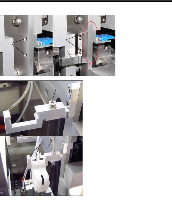
4.7.1 Checking needle height
Detail:
55
52
28 |
51 |
53 |
Fig. 13
46
55
The height of the dispenser needle must be aligned to the specimen slide correctly so that no air bubbles are generated while the mountant is applied. The dispenser needle height must not be set too low in order to avoid damage to the specimen on the specimen slide.
Aligning the dispenser needle:
•Switch off the instrument and unplug it.
•Open the service door (28) as outlined in Chap. 4.6 (Fig. 7).
•Remove the cover slip catch tray that may already be attached at the specimen slide outfeed.
•Movethedispenserwiththedispenserneedle into the working position.
•Thereisapulley(51) that moves the specimen slide outfeed (52) in the area near the opened service door. This can be used to move the specimen slide outfeed to the left and right (see yellow arrow, Fig. 13, 51).
•The dispenser needle can be moved backward and forward in the working position (see Fig. 13, 53) carefully by hand using the Pick & Place module.
Caution!
Do not cause the Pick & Place module to make any downward motion.
•Now align the highest point of the specimen slide outfeed (see Fig. 14, 55) and the tip of the dispenser needle so that they are touching.
Fig. 14
26 |
Instructions for Use V 3.0 RevE – 04/2013 |

4. Instrument Setup
4.7.2. Setting the needle height
39 |
35 |
|
Fig. 15
56
57
54 
Fig. 16
The needle height has to be corrected after reinserting the dispenser needle.
Setting the needle height:
•Reset the dispenser (35) from the working position (see Fig. 16, 57) to the rest position (see Fig. 15, 39).
•There is a screw (see Fig. 16, 54) in the working position. This determines the distance between the dispenser needle and specimen slide.
•The height of the dispenser can be changed by rotating the screw using a No. 3 Allen key (56) (standard delivery):
-Rotating clockwise decreases the distance.
-Rotating counterclockwise increases the distance.
•Keep rotating the screw clockwise until the dispenser needle is touching the highest point of the specimen slide outfeed (see Fig. 14, 55) (distance = 0 mm). This can be checked by putting the dispenser into the working position.
Leica CV5030 – Robotic Coverslipper |
27 |

4 Instrument Setup
4.7.2 Setting the needle height (continued)
•The dispenser is reset into the rest position if the 0 mm distance is set correctly.
•Nowcarryoutathree-quarterscounterclock- wise revolution using the No. 3 Allen key.
•This achieves the optimum distance of 0.75 -
0.8 mm.
•The set height of the dispenser needle can be inspected again by a visual inspection from the front (see Fig. 14).
•Then close the service door, screw it down tight and reconnect the instrument to the power supply.
28 |
Instructions for Use V 3.0 RevE – 04/2013 |

4. Instrument Setup
4.8Dispenser needle cleaner (nozzle cleaner)
The dispenser needle cleaner is used to clean excess coverslip mountant off of the dispenser needle after each specimen slide processed.
1 |
3 |
7 |
9 |
5 |
8
4
10
2 |
6 |
Fig. 17
Assembly
Parts
Remove the individual components from the packaging and check them for completeness.
The following must be present:
•Container (1) with lid (10)
•Brush (2) (2x)
•Holder (3) with hexagon socket screw (7) and shim (8)
•Mounting bracket (4) 2 hexagon socket screws (9)
•Plastic pipette (5)
•No. 3 Allen key (6)
The dispenser needle cleaner consists of a container (for the cleaning fluid) into which a brush is inserted. The brush is moistened with solvent using felt strips (19).
2 |
16 |
10 |
19
15
|
|
|
Fig. 18
•Insert the brush (2) into the container so that the lateral guides (15) (2 each on the left and right) fit into the notches (16) provided.
•Now, attach the lid (10) and push it down until it clicks into place.
Leica CV5030 – Robotic Coverslipper |
29 |
4.Instrument Setup
4.8Dispenser needle cleaner (nozzle cleaner) (continued)
|
12 |
|
Assembly |
|
|
To install the holder for the |
|
|
|
|
dispenser needle cleaner, you |
|
9 |
|
must first remove the transport |
11 |
4 |
|
anchors for the Pick & Place |
|
|
module (see Chap. 4.3.1, Fig. 5). |
|
|
|
|
For installation, use the thread- |
|
|
|
ed holes (11) of the transport |
|
|
|
anchor (see Fig. 19/1). |
|
|
|
|
7, 8
3
17 6
1
Fig. 20
Fig. 19
•First, fasten the mounting bracket (4) in the bores (11) in the housing wall (12) using the two screws (9) (Fig. 19/2). Make sure that the mounting bracket is parallel to the edge of the housing wall (ellipse, in Fig. 19/2).
•Then, fasten the holder (3) on the mounting bracket using the screw (7) and shim (8).
•Insert the completely assembled dispenser needle cleaner (1) into the holder as shown in Fig. 20/2. Press down to ensure that the two lateral mounting clips (17) audibly engage in the notches of the bracket.
30 |
Instructions for Use V 3.0 RevE – 04/2013 |
Loading...