


 Loading...
Instructions for Use
Leica ASP200 S -
Advanced Smart Processor
Vacuum
Tissue Processor
Leica ASP200 S, V 1.4 RevE, English – 03/2013 Order No.: 14 0480 80101, RevE
Always keep this manual with the instrument. Read carefully before working with the instrument.

WARNING
The information, numerical data, notes and value judgments contained in this manual represent the current state of scientific knowledge and state-of-the-art technology as we understand it following thorough investigation in this field.
We are under no obligation to update the present manual periodically and on an ongoing basis according to the latest technical developments, nor to provide our customers with additional copies, updates etc. of this manual.
For erroneous statements, drawings, technical illustrations etc. contained in this manual we exclude liability as far as permissible according to the national legal system applicable in each individual case. In particular, no liability whatsoever is accepted for any financial loss or consequential damage caused by or related to compliance with statements or other information in this manual.
Statements, drawings, illustrations and other information as regards contents or technical details of the present Instructions for Use are not to be considered as warranted characteristics of our products.
Leica Biosystems Nussloch GmbH Heidelberger Str. 17 - 19
D-69226 Nussloch Germany
Phone: +49 6224 143-0
Fax: +49 6224 143-268
Internet: http://www.LeicaBiosystems.com
These are determined only by the contract provisions agreed between ourselves and our customers.
Leica reserves the right to change technical specifications as well as manufacturing processes without prior notice. Only in this way is it possible to continuously improve the technology and manufacturing techniques used in our products. This documentation is protected under copyright laws. All copyrights to this documentation are held by Leica Biosystems Nussloch GmbH.
Any reproduction of text and illustrations (or of any parts thereof) by means of print, photocopy, microfiche, web cam or other methods – including any electronic systems and media requires express prior permission in writing by Leica Biosystems Nussloch GmbH.
For the instrument serial number and year of manufacture, please refer to the name plate at the back of the instrument.
© Leica Biosystems Nussloch GmbH
Leica ASP200 S |
3 |

Contents
1. |
Important Information................................................................................................................ |
6 |
|
|
1.1 |
Symbols in the text and their meanings.................................................................................... |
6 |
|
1.2 |
Qualification of personnel............................................................................................................ |
8 |
|
1.3 |
Intended use of instrument.......................................................................................................... |
8 |
|
1.4 |
Instrument type.............................................................................................................................. |
8 |
2. |
Safety............................................................................................................................................ |
9 |
|
|
2.1 |
Safety notes................................................................................................................................... |
9 |
|
2.2 |
Warnings........................................................................................................................................ |
9 |
|
2.3 |
Safety features on the instrument............................................................................................ |
13 |
3. |
Instrument Components and Specifications....................................................................... |
14 |
|
|
3.1 |
Overview - instrument components......................................................................................... |
14 |
|
3.2 |
Specific instrument options....................................................................................................... |
16 |
|
3.3 |
Standard delivery - packing list................................................................................................ |
17 |
|
3.4 |
Technical Data............................................................................................................................. |
19 |
|
3.5 |
Compatible reagents................................................................................................................... |
21 |
|
3.6 |
Recommended reagent handling............................................................................................. |
22 |
|
3.6.1 |
Cycle for changing reagents..................................................................................................... |
23 |
4. |
Initial Operation........................................................................................................................ |
24 |
|
|
4.1 |
Installation site requirements................................................................................................... |
24 |
|
4.1.1 |
Moving the instrument............................................................................................................... |
24 |
|
4.2 |
Electrical connection.................................................................................................................. |
25 |
|
4.2.1 |
Connecting the power supply................................................................................................... |
25 |
|
4.2.2 |
Connecting an uninterruptible power supply (UPS).............................................................. |
26 |
|
4.3 |
Installing accessories................................................................................................................ |
27 |
|
4.4 |
Making the data connections................................................................................................... |
29 |
|
4.5 |
Anti-reflection clip – Function................................................................................................... |
30 |
|
4.6 |
Alarm functions........................................................................................................................... |
31 |
|
4.7 |
Switching the instrument on..................................................................................................... |
32 |
|
4.8 |
Touchscreen functions.............................................................................................................. |
34 |
|
4.9 |
Checklist for initial operation.................................................................................................... |
35 |
|
4.10 |
Switching off the instrument..................................................................................................... |
36 |
5. |
Operation................................................................................................................................... |
37 |
|
|
5.1 |
Setting up the instrument parameters..................................................................................... |
37 |
|
5.1.1 |
System setup................................................................................................................................ |
37 |
|
5.1.2 |
Access levels............................................................................................................................... |
40 |
|
5.1.3 |
INSTALLATION menu................................................................................................................. |
42 |
4 |
Instructions for Use V 1.4, RevE – 03/2013 |

|
|
|
Contents |
|
|
|
|
|
5.1.4 |
Editing the reagent list................................................................................................................ |
45 |
|
5.1.5 |
Viewing the program list............................................................................................................ |
48 |
|
5.1.6 |
Adding and/or modifying programs.......................................................................................... |
49 |
|
5.1.7 |
Favorites....................................................................................................................................... |
52 |
|
5.1.8 |
Configuring the stations............................................................................................................. |
54 |
|
5.1.9 |
Reagent groups........................................................................................................................... |
55 |
|
5.2 |
Reagent handling........................................................................................................................ |
56 |
|
5.2.1 |
Draining/filling reagents (other than paraffin)........................................................................ |
56 |
|
5.2.2 |
Replacing the paraffin................................................................................................................ |
58 |
|
5.3 |
Running programs....................................................................................................................... |
61 |
|
5.3.1 |
Editing a program that has been called up. ........................................................................... |
62 |
|
5.3.2 |
Starting a program...................................................................................................................... |
64 |
|
5.3.3 |
Opening the retort during a program interruption................................................................. |
65 |
|
5.3.4 |
Retort emergency release......................................................................................................... |
65 |
|
5.4 |
Reagent status............................................................................................................................. |
67 |
|
5.5 |
System monitor............................................................................................................................ |
68 |
|
5.6 |
The online help............................................................................................................................ |
69 |
6. |
Troubleshooting........................................................................................................................ |
70 |
|
|
6.1 |
General.......................................................................................................................................... |
70 |
|
6.2 |
Power failure................................................................................................................................ |
70 |
|
6.3 |
Troubleshooting........................................................................................................................... |
71 |
|
6.4 |
Typical fill or drain problems..................................................................................................... |
72 |
7. |
Cleaning and Maintenance.................................................................................................... |
73 |
|
|
7.1 |
Clean programs........................................................................................................................... |
73 |
|
7.1.1 |
Retort cleaning programs.......................................................................................................... |
73 |
|
7.1.2 |
Paraffin cleaning......................................................................................................................... |
75 |
|
7.1.3 |
Smart clean.................................................................................................................................. |
76 |
|
7.2 |
General cleaning steps.............................................................................................................. |
77 |
|
7.2.1 |
Daily cleaning and maintenance.............................................................................................. |
79 |
|
7.2.2 |
Periodic cleaning and maintenance........................................................................................ |
81 |
|
7.3 |
Checklist for preventive maintenance..................................................................................... |
83 |
8. |
Warranty and Service.............................................................................................................. |
85 |
|
Appendix 1 |
............................................................................................................................................ |
86 |
|
|
Notes on Specimen Preparation.......................................................................................................... |
86 |
|
Leica ASP200 S |
5 |

1.Important Information
1.1 Symbols in the text and their meanings
Warnings
appear in a gray box and are marked by a warning triangle  .
.
Notes,
i.e. important user information appear in a gray box and are marked by an – information symbol  .
.
Inflammable solvents and reagents are marked with this symbol.
Instrument surfaces which become hot during operation are marked with this symbol.
Avoid direct contact with these surfaces - they may cause burns.
(5)Numbers in parentheses refer to item numbers in illustrations.
ENTER Function keys to be pressed on the instrument touchscreen are written in bold-print capital letters.
Manufacturer
 In vitro diagnostics (IVD) medical device
This product fulfills the requirements of the Council's Directive 98/79/EC concerning in vitro diagnostics (IVD) medical devices.
Environmental protection symbol of the China RoHS directive. The number in the symbol indicates the "Environmentfriendly Use Period" of the product. The symbol is used if a substance restricted in China is used in excess of the maximum permitted limit.
Symbol for labeling electrical and electronic equipment in accordance with Section 7 of the German Electrical and Electronic Equipment Act (ElektroG). ElektroG is the law regarding the sale, return and environmentally sound disposal of electrical and electronic equipment.
6 |
Instructions for Use V 1.4, RevE – 03/2013 |

1. Important Information
1.1 Symbols in the text and their meanings (continued)
SN Serial number
REF Order No.
Observe the Instructions for Use
The package contents are fragile and must be handled with care.
Indicates the correct upright position of the package.
The package must be kept in a dry environment.
Indicates the temperature range to which the medical device can be safely exposed.
Minimum –29 °C Maximum +50 °C
Indicates the air humidity range to which the medical can be safely exposed.
Minimum 10 %
Maximum 85 %
Example of labeling in accordance with IPPC.
•IPPC symbol
•Country code in accordance with ISO 3166, e.g. DE for Germany
•Regional identifier, e.g. HE for Hessen
•Producer/treatment provider code, unique assigned number starting with 49
•Treatment code, e.g. HT (heat treatment), MB
(methyl bromide), and possibly DB (debarked).
Tip-n-Tell indicator to monitor whether the shipment has been transported and stored in upright position according to your requirements. With a pitch of 60 ° or more, the blue quartz sand flows into the arrow-shaped indicator window and sticks there permanently. Improper handling of the shipment is immediately detectable and can be proven definitively.
Leica ASP200 S |
7 |

1.Important Information
1.2 Qualification of personnel
•The Leica ASP200 S may be operated by trained laboratory personnel only.
•All laboratory personnel designated to operate this instrument must read these Instructions for Use carefully and must be familiar with all technical features of the instrument before attempting to operate it.
1.3 Intended use of instrument
The instrument has been designed so that it is safe to use by the operator as well as for processing specimens – provided that it is operated according to the present Operating Manual. The Leica ASP200 S is a modular automated tissue processor designed for the following laboratory applications:
•Fixation
•Dehydration
•Paraffin infiltration
of histological tissue specimens.
The Leica ASP200 S must be operated exclusively with the reagents listed in Chap. 3.5 - "Compatible reagents".
Any other use of the instrument is considered improper.
Failure to adhere to these instructions may result in an accident, personal injury, damage to the instrument or accessory equipment.
Proper and intended use includes compliance with all inspection and maintenance instructions, along with the observance of all instructions in the Instructions for Use.
1.4 Instrument type
All information provided in these Instructions for Use applies only to the instrument type indicated on the cover page.
A nameplate indicating the instrument serial number is attached to the rear side of the instrument. (The serial number is also displayed above the loading door on the front side of the instrument.)
Fig. 1
Fig. 1 is provided as an example only and shows a valid nameplate for this instrument with the necessary information about instrument type and power requirement. The precise data for the various versions is specified in Chap. 3.2 "Technical data".
8 |
Instructions for Use V 1.4, RevE – 03/2013 |
2. Safety
2.1Safety notes
•The safety and caution notes in this chapter must be observed at all times.
•Be sure to read these notes even if you are already familiar with the operation and use of other Leica products.
•The protective devices located on the instrument and the accessories must not be removed or modified. Only qualified service personnel authorized by Leica may repair the instrument and access its internal components.
Residual risks
•The instrument has been designed and constructed with the latest state-of-the-art technology and according to recognized standards and regulations with regard to safety technology. Operating or handling the instrument incorrectly can place the user or other personnel at risk of injury or can cause damage to the instrument or other property. The instrument may be used only as intended and only if all of its safety features are in proper working condition. Malfunctions which could impede safety must be remedied immediately.
•Only original spare parts and permitted original accessories may be used.
These Instructions for Use includes important information related to the operating safety and maintenance of the instrument.
The Instructions for Use are an important part of the product, and must be read carefully prior to startup and use and must always be kept near the instrument.
This instrument has been built and tested in accordance with the safety requirements for electrical equipment for measurement, control, and laboratory use.
To maintain this condition and ensure safe operation, the user must observe all notes and warnings contained in these Instructions for Use.
These Instructions for Use must be appropriately supplemented as required by the existing regulations on accident prevention and environmental safety in the operator‘s country.
For current information about applicable standards, please refer to the CE declaration for the instrument and to our Internet site:
http://www.LeicaBiosystems.com
2.2Warnings
The safety devices installed in this instrument by the manufacturer only constitute the basis for accident prevention. Operating the instrument safely is, above all, the responsibility of the owner, as well as the designated personnel who operate, service or repair the instrument.
To ensure trouble-free operation of the instrument, be sure to comply with the following instructions and warnings.
Leica ASP200 S |
9 |

2.Safety
2.2 Warnings (continued)
Warnings – Markings on the instrument itself
Markings on the instrument showing the warning triangle indicate that the correct operating instructions (as defined in these Instructions for Use) must be followed when operating or replacing the item marked. Failure to adhere to these instructions may result in an accident, personal injury, damage to the instrument or accessory equipment.
Some instrument surfaces become hot during operation. They are marked with this warning label. Touching these surfaces may cause burns.
Transport and Installation
Once unpacked, the instrument may be transported only in an upright position. Follow the unpacking instructions carefully to avoid damage to the instrument!
Prior to every transport in which it is possible for the instrument to be shaken, tilted, or lifted, it must be cleaned for transport – otherwise the interior of the instrument can be severely damaged.
Plug the instrument only into a grounded power socket. Do not interfere with the grounding function by using an extension cord without a ground wire.
Make sure to observe the voltage settings!
The set voltage CANNOT be changed by the user.
Severe damage may occur if the instrument is connected to a power supply voltage other than that to which it was originally set.
The installation location must be well-ventilated; there should be no ignition sources there of any kind. The chemicals to be used in the Leica ASP200 S are both flammable and noxious.
Do not operate the instrument in rooms with explosion hazard.
Extreme temperature fluctuations between storage facility and setup site as well as high humidity may cause condensation to form. If this is the case, wait at least two hours before switching on the instrument. Failure to comply with this may cause damage to the instrument.
10 |
Instructions for Use V 1.4, RevE – 03/2013 |
2. Safety
2.2 Warnings (continued)
Warnings – Operating the instrument
The instrument may only be operated by trained laboratory personnel. It must only be operated for the purpose of its designated use and according to the instructions contained in these Instructions for Use.
In an emergency, the instrument can be switched off while working with specimens via the ON/STOP switch located on the side of the instrument.
Before opening the retort when an infiltration process is in progress, always press the PAUSE button so that the retort is ventilated or vented.
The paraffin drain hose and the hose for remote filling/draining are cleaned with compressed air after the filling or draining process.
Therefore, never remove the hoses before a filling or draining process has been completed.
After refilling/replacing reagent containers, close the container covers again tightly.
The reagent containers must be properly pushed home into the connection manifolds at the rear inner wall of the reagent module.
Failure to plug the reagent containers into the manifold correctly will interrupt the infiltration process and may also result in spilling of reagents.
Fixing solutions that contain mercury salts, acetic acid, or picric acid can cause corrosion on metal components.
After each paraffin step a retort clean cycle must be run.
Material safety data sheets can be obtained from the supplier of the chemicals.
Alternatively, they can be downloaded from the following website:
http://www.msdsonline.com
Leica ASP200 S |
11 |

2.Safety
2.2 Warnings (continued)
Warnings – Handling reagents
Take care when handling solvents!
Always wear rubber gloves and safety goggles when handling the chemicals used in this instrument.
Reagents used for tissue infiltration can be both toxic and/or flammable.
To prevent damage to the instrument, use only the reagents listed in Chap. 3.5!
Do not use acetone, benzene or trichlorethane!
Use caution when handling paraffin wax or removing baskets – molten paraffin is hot and may cause burns.
Also, avoid personal contact with paraffin reservoirs and retort walls – they can be very hot as well.
When disposing of spent reagents, observe the applicable local regulations and the waste disposal regulations of the company/institution in which the instrument is being operated.
Do not clean reagent containers (bottles) in a dishwasher; the containers are NOT dishwasherproof.
Warnings – Cleaning and maintenance
Switch off the instrument each time before servicing and pull out the power plug.
Do not clean the instrument with solvents containing acetone or xylene. No liquid may be spilled into the internal components of the instrument – neither during operation nor during cleaning.
When using cleaners, please comply with the safety instructions of the manufacturer and the laboratory safety regulations.
Check the condensate container at least once a week and, if necessary, drain it.
12 |
Instructions for Use V 1.4, RevE – 03/2013 |

2. Safety
2.3 Safety features on the instrument
The Leica ASP200 tissue processor is equipped with numerous safety functions and with sophisticated software control mechanisms. These ensure that the specimens remain undamaged in the event of a power failure or other malfunction during the infiltration process and that the infiltration is completed successfully.
Overpressure protection
•When power is off the air pump and air valves default to a safe condition
(retort vented, no pressure generation).
•If the pump is not stopped at the correct moment during the pressurization, the power supply is interrupted by a separate electronic circuit.
•In addition, there is a safety relief valve that vents all excess air pump output to atmosphere.
Overcurrent protection
•Overcurrent conditions are protected against by both the main fuse and the separate heating power fuses.
Overheating protection
An error is indicated and all heating is stopped by the microprocessor – control if the instrument detects any of the following conditions:
•Abnormally high temperature (>75 °C)
•Contradictory results of the temperature sensors
•Failure of one or more heating power control components
•If the microprocessor fails to interrupt heating power, independent temperature limiting hardware circuits limit the temperature rise to a safe level.
•If the temperature limiting circuits malfunction, an independent hardware thermal fuse circuit cuts power to the heating elements.
Over vacuum protection
•The vacuum system is not capable of generating a dangerous vacuum condition.
Overcurrent protection
•Overcurrent conditions are protected against by both the main fuse and the separate heating power fuses.
Leica ASP200 S |
13 |

3.Instrument Components and Specifications
3.1 Overview – instrument components
3 |
|
4 |
|
|
24 |
1 |
6 |
|
|
22 |
|
|
|
|
5 |
|
7 |
10 |
9 |
|
|
|
|
23
20
21
12 11 8
13 |
|
19 |
|
17 |
18 |
||
|
2
15
14
16
Fig. 2
14 |
Instructions for Use V 1.4, RevE – 03/2013 |

3. Instrument Components and Specifications
Overview – instrument components
1- Basic instrument – processor module
2- Basic instrument – reagent module
3- Wax bath lids
4- Retort lid
5 - Monitor
6- Cover flap of the instrument console
7- Instrument console with:
8- Printer port
9- Local alarm connection
10- Remote alarm connection
11- Disk drive
12- Serial port
13- Active carbon filter
14- Condensate container
15- Reagent containers (13 units)
16- Drip tray
17- Paraffin drain spout
18- Remote drain connection
19- Retort
20- Wax baths
21- Cassette basket
22- Lid for cassette basket
23- Basket carrier
24- Baffle plate
25- Volume replacement body
Instrument Components and Accessories
Three wax baths and the retort comprise the infiltration module.
The touchscreen and the electronic components are there.
The cassettes are stored in two baskets (Fig. 2, 21) each of which holds up to 84 cassettes with dividing spiral or up to 100 cassettes without dividing spiral.
The specimens are processed in the stainless steel retort at the preselected pressure, vacuum, and temperature conditions.
The reagent containers are located in the reagent cabinet.
Leica ASP200 S |
15 |

3.Instrument Components and Specifications
3.2Specific instrument options
•Optionally usable Reagent Management System (RMS), displays service life and usage frequency of the individual reagents and enables automatic definition of the reagent sequence
– there is no more need to rearrange reagent containers. If one or more reagents within a sequence are replaced, the RMS automatically uses the reagents in the correct sequence, organized in ascending order of cleanliness.
•Liquid movement ("wave motion") during the process for better and continuous mixture of the reagents.
•System for non-contact filling/draining of reagents – drains and fills the reagent container using a hose connected to the infiltration module without the operator being exposed to reagents in the process.
•Non-contact wax bath drainage.
•Optical level meter.
•Active paraffin cleaning program – removes solvent residue from the paraffin, lengthening its service life.
•Magnetic stirrer – for gentle circulation of the reagents, thus ensuring a uniform reagent temperature.
•Programmable end time for infiltration programs.
•3-step drainage of the retort (adjustable) for reducing reagent displacement.
•Infiltration process at ambient pressure, or with pressure, vacuum or a combination of both.
•Four programmable cleaning programs. The cleaning programs automatically omit all steps that are not necessary to complete the cleaning procedure.
16 |
Instructions for Use V 1.4, RevE – 03/2013 |

3. Instrument Components and Specifications
3.3 Standard delivery - packing list
To prevent damage to the instrument or specimens, only accessories and spare parts authorized by Leica may be used.
The standard equipment of the Leica ASP200 S includes the following parts: |
Part No. |
|||
1 Leica ASP200 S basic instrument |
|
|||
13 |
Reagent bottles, plastic (in the instrument) |
14 0480 37121 |
||
1 |
Condensate container, plastic (in the instrument) |
14 0480 37122 |
||
1 |
Collecting vessel (in the instrument) |
14 0476 37350 |
||
1 |
3.5 " diskette, empty (affixed to the rear side of the console cover) |
14 0476 35915 |
||
1 |
Accessory kit, consisting of: |
14 0480 43728 |
||
|
1 |
Basket set ASP200 S, consisting of: |
14 0480 43577 |
|
|
|
1 |
Basket handle ASP200 S |
14 0476 34713 |
|
|
1 |
Basket carrier ASP200 S |
14 0480 43578 |
|
|
2 Plastic baskets with integrated spacers |
14 0476 43569 |
|
|
|
1 Stainless steel basket cover for the top basket |
14 0476 43362 |
|
|
1 |
Stirrer |
14 0476 43630 |
|
|
1 |
Volume replacement body |
14 0480 37127 |
|
|
1 |
Reagent bottle, plastic |
14 0480 37121 |
|
|
2 |
Set of adhesive bottle labels, 24 pcs. each |
14 0200 43464 |
|
|
1 |
Funnel |
14 0476 43631 |
|
|
2 |
Active carbon filter assembly |
14 0476 34150 |
|
|
1 |
Filling/draining hose assembly |
14 0476 34716 |
|
|
1 |
Paraffin drain hose |
14 0476 34721 |
|
|
1 |
Paraffin scraper, plastic |
14 0476 35923 |
|
|
1 |
Lubricant for valves and O-rings (Molykote 111, 100 gr) |
14 0336 35460 |
|
|
1 |
Connecting cable - power supply |
14 0411 34604 |
|
|
1 |
Maintenance kit (2 spare covers, 9 O-rings) |
14 0476 35921 |
|
|
1 |
Baffle plate |
14 0476 34770 |
|
|
1 |
Single-head wrench, size 27 |
14 0330 50891 |
|
|
1 |
Allen key, size 3.0 |
14 0222 04138 |
|
Leica ASP200 S |
17 |
3.Instrument Components and Specifications
3.3Standard delivery – packing list (continued)
|
|
|
Part No. |
|
1 |
Remote alarm connection, 6.3 mm |
14 6844 01005 |
|
1 |
Cleaning tools for prism |
14 0495 47955 |
|
1 |
Microfiber cloth for prism |
14 0495 47736 |
1 |
Power cable for Germany |
14 0411 13558 |
|
1 |
Power cable for UK ST-BU F-5 A |
14 0411 27822 |
|
1 |
Power cable for Brazil 10 A, straight |
14 0411 47869 |
|
1 |
Power cable for the USA/Canada/Japan (for voltage variant 100-120 V) |
14 0411 13559 |
|
1 |
ASP200 S German/English Instructions for Use (+ language CD) |
14 0480 80001 |
|
1 |
Language CD, with ASP200 S demo program |
14 0480 80200 |
|
Please check all delivered parts against the packing list and against your order to verify whether the delivery is complete! Should you find any discrepancies, please contact your Leica sales office without delay.
18 |
Instructions for Use V 1.4, RevE – 03/2013 |

3. Instrument Components and Specifications
3.4 Technical Data
Nominal supply voltages: |
Two factory-preset voltages (not user-adjustable): |
|
|
100 to 120 V |
or |
|
230 to 240 V |
|
Nominal frequency: |
50 to 60 Hz |
|
Main fuses: |
2 melting fuses, 20 x 5 mm, UL-approved |
|
|
• for 100 to 120 V F 10 A 250 VAC |
|
|
• for 230 to 240 V F 5 A 250 VAC |
|
Nominal power: |
1000 VA |
|
Dimensions, (L x W x H), in mm: |
595 x 680 x 1325 |
|
Empty weight, unpacked: |
approx. 160 kg |
|
Weight, packed: |
220 kg |
|
Operating temperature range: |
15 °C to 35 °C |
|
Relative humidity: |
10 % to 80 % non-condensing |
|
IEC 1010 classification: |
Protection class 1 |
|
|
Pollution degree 2 |
|
|
Overvoltage installation category II: |
|
|
• 800 V impulse (120 V systems) |
|
|
• 1500 V impulse (240 V systems) |
|
Altitude: |
2500 m maximum |
|
Local/remote alarm relay: |
30 V DC, maximum 2 A |
|
|
2 terminals: |
|
|
Each with isolated switching contact (operable both |
|
|
as normally-open and normally-closed circuit) |
|
Paraffin reservoirs |
|
|
Number of containers: |
3 |
|
Capacity: |
4.3 l per container |
|
Melting time: |
approx. 10 h |
|
Temperature: |
40 to 65 °C |
|
Temperature accuracy: |
+ 1 K |
|
Leica ASP200 S |
19 |

3.Instrument Components and Specifications
3.4 Technical data (continued)
Retort |
|
Capacity: |
max. 200 cassettes |
Reagent volume: |
3.5 l with volume replacement body |
Temperature (paraffin): |
40 to 65°C |
Temperature (processing reagents): |
|
Ambient temperature or 35 to 55°C |
|
|
|
Temperature (cleaning reagents): |
50 to 65 °C |
Temperature accuracy: |
+ 1 K |
Filling time: |
approx. 90 sec |
Drain time: |
approx. 80, 120, 140 sec (selectable) |
Impregnation vacuum: |
-70 kPa (g) |
Infiltration pressure: |
35 kPa (g) |
Filling vacuum: |
-70 kPa (g) |
Draining pressure: |
35 kPa (g) |
General |
|
Reagent container: |
10 |
Cleaning solution bottles: |
3 |
Maximum bottle volume: |
4.0 l |
Printer: |
Optional Accessories |
Pretest check: |
ON/OFF |
Fluid level sensor: |
ON/OFF |
Recirculation (pump in/out): |
ON/OFF |
(a) Time before 1st cycle: |
16 min |
(b) Time between cycles: |
20 min |
System setup |
|
Password status: |
Supervisor/Operator |
Type of password: |
alphanumeric, freely selectable |
Reagent management system (RMS): |
ON/OFF |
Software interlock: |
ON/OFF |
20 |
Instructions for Use V 1.4, RevE – 03/2013 |
3. Instrument Components and Specifications
3.4 Technical data (continued)
Hardware and Software:
•Large color LCD touchscreen.
•User-friendly, intelligent software.
•3.5" disk drive and printer port.
•Alarm system with two remote alarm sockets.
•Password-protected instrument supervisor mode.
•Built-in multiple specimen protection system.
Capacities:
•15 programs that consist of up to 10 reagent and 3 paraffin processing steps each.
•Time per program step: 0 to 99 h, 59 min.
•Delay time: max. 7 days
•Up to 200 cassettes can be processed simultaneously.
•4 programmable cleaning programs for the retort.
•1 paraffin cleaning program
•10 reagent containers.
•3 paraffin reservoirs.
•3 containers for cleaning solutions
•1 condensate container
•Reagent temperature selectable from 35 °C to 55 °C or room temperature.
•Paraffin temperature selectable from 40 °C to 65 °C.
•Choice of three retort drain rates of 80, 120 or 140 seconds.
•Up to 100 reagent names in memory.
3.5Compatible reagents
Use of the ASP200 S is permitted with the reagents specified in Chap. 3.5 only. These reagents must be validated before use, i.e. tissue processing with patient tissue for diagnostics, by the laboratory itself according to the local or regional accreditation requirements. Reagents other than those listed here may cause severe damage to the components of the instrument. Acetone, benzene, chloroform and trichlorethane must NOT be used!
Leica ASP200 S |
21 |

3.Instrument Components and Specifications
3.5 Compatible reagents (continued)
The following reagents may be used in the Leica ASP200 S:
Fixatives |
Dehydration |
Clearing |
Paraffinizing |
|||
1st |
Formalin |
1st |
Ethanol |
1st |
Xylene |
1st Wax |
|
(buffered or |
2nd |
Isopropanol |
2nd |
Toluene* |
|
|
unbuffered) |
|
||||
|
3. |
Methanol |
3. |
Chloroform* |
|
|
|
|
|
||||
2nd |
Formalin re- |
4. |
Butyl alcohol |
|
|
|
|
placement |
|
|
|
|
|
5.Industrial methylated spirits
*Before using these reagents, please obtain information from Leica or the supplier about required preventive measures.
Fixatives containing mercuric salts, acetic or picric acid will corrode metallic components in the instrument and shorten instrument life.
If you choose to work with such fixatives, it is essential to perform a clean cycle which contains multiple water rinses each time after use, to minimize damage.
In addition, we recommend frequent and regular preventive maintenance by the Leica Technical Service.
Reagents other than those listed here may damage some components of the instrument. Do not use acetone, benzene or trichlorethane in the instrument.
3.6Recommended reagent handling
•The reagents used should be replaced after 600 to 1200 specimens have been processed or after 6 cycles of 100 to 200 specimens each.
•For formalin, process alcohol and process xylene reagents, ambient temperature is recommended.
•The recommended temperature for cleaning reagents in the cleaning cycle is 65 °C.
•Only zinc formalin based on zinc sulfates may be used in the ASP200 S/ASP300 S. If zinc formalin is used, the cleaning program must include an additional cleaning water step.
•The use of formalin reagents containing zinc chloride can cause corrosion in and on the instrument.
22 |
Instructions for Use V 1.4, RevE – 03/2013 |

3. Instrument Components and Specifications
3.6.1 Cycle for changing reagents
Reagent |
Week 1 |
Week 2 |
Week 3 |
Week 4 |
|
|
|
|
|
Formalin |
At least 3 times a |
At least 3 times a |
At least 3 times a |
At least 3 times a |
|
week |
week |
week |
week |
Formalin |
At least 3 times a |
At least 3 times a |
At least 3 times a |
At least 3 times a |
|
week |
week |
week |
week |
70 % |
Daily |
Daily |
Daily |
Daily |
80 % |
Once a week |
Once a week |
Once a week |
Once a week |
95 % |
Once a week |
--- |
Once a week |
--- |
|
|
|
|
|
95 % |
--- |
Once a week |
--- |
Once a week |
100 % |
Once a week |
--- |
Once a week |
--- |
100 % |
--- |
Once a week |
--- |
Once a week |
Xylene |
Once a week |
--- |
Once a week |
--- |
Xylene |
--- |
Once a week |
--- |
Once a week |
Paraffin 1 |
Run paraffin clean- |
Run the paraffin |
Run the paraffin |
Run paraffin clean- |
|
ing program* daily. |
cleaning program* |
cleaning program* |
ing program* daily. |
|
Replace the paraf- |
once a week. |
twice a week. |
Replace the paraf- |
|
fin after 6 cleaning |
|
|
fin after 6 cleaning |
|
cycles. |
|
|
cycles. |
Paraffin 2 |
Run the paraffin |
Run paraffin clean- |
Run the paraffin |
Run the paraffin |
|
cleaning program* |
ing program* daily. |
cleaning program* |
cleaning program* |
|
twice a week. |
Replace the paraf- |
once a week. |
twice a week. |
|
|
fin after 6 cleaning |
|
|
|
|
cycles. |
|
|
Paraffin 3 |
Run the paraffin |
Run the paraffin |
Run paraffin clean- |
Run the paraffin |
|
cleaning program* |
cleaning program* |
ing program* daily. |
cleaning program* |
|
once a week. |
twice a week. |
Replace the paraf- |
once a week. |
|
|
|
fin after 6 cleaning |
|
|
|
|
cycles. |
|
Cleaning xylene |
Once a week |
Once a week |
Once a week |
Once a week |
Cleaning alcohol |
Once a week |
Once a week |
Once a week |
Once a week |
Cleaning Water |
Once a week |
Once a week |
Once a week |
Once a week |
* Paraffin cleaning program, see Chap. 7.1.2
Leica ASP200 S |
23 |
4.Initial Operation
4.1 Installation site requirements
•The instrument requires an installation area of approx. 650 x 700 mm with vibration-free floor.
•Room temperature consistently between +15 °C and +35 °C.
•Relative air humidity maximum 80 %, noncondensing.
•Avoid vibrations, direct sunlight and heavy variations in temperature.
4.1.1Moving the instrument
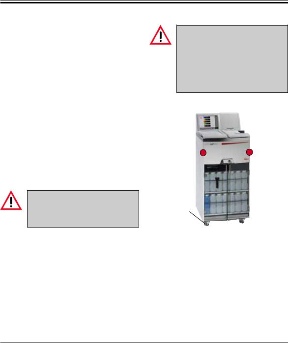
After unpacking the instrument (see Unpacking instructions on the outside of the transport crate), handle it only by the handles marked with ‘ ‘ to move it to its final location.
When operating the instrument, the brakes on the instrument casters (24) must be engaged.
The instrument must be set up so that the power switch on the rear side of the instrument (Fig. 4, 42) is easily accessible at any time.
The chemicals to be used in the Leica ASP200 S are both flammable and noxious. The installation site for the Leica ASP200 S must be well ventilated, and there must be no ignition sources of any kind in the area. Never operate the instrument in rooms with an explosion hazard.
24
24 |
Instructions for Use V 1.4, RevE – 03/2013 |

4. Instrument Setup
4.2 Electrical connection
Notice!
Observe the following instructions carefully to prevent damage to the instrument (refer also to Chap. 2.2 "Warnings – Transport and installation").
•Check the voltage label (Fig. 3) on the rear of the instrument to ensure that the instrument delivered is set to the correct voltage range.
Severe damage may occur if the instrument is connected to a power supply voltage other than that to which it was originally set.
The power supply voltage for the instrument is factory preset and CANNOT be altered by the user.
Fig. 3
4.2.1 Connecting the power supply
Once the instrument has been switched on, the main switch (ON/OFF) (5) should always remain in the ON position.
41
 42
42
 40
40
43
Left Fig.
Electrical ports on the rear panel of the instrument.
37• Connect the power cable (37) to the input socket (41) of the main power supply.
•The jumper cable provided
(38) connects the output of the main power supply (43) to the input of the electronics module (40).
38
Fig. 4
Right Fig.
Correct connection of the cables.
Important!
The specification for the connection (40) is specified as follows:
100 - 120 V or
230 - 240 V, maximum 200 VA.
Leica ASP200 S |
25 |

4.Initial Operation
4.2.2 Connecting an uninterruptible power supply (UPS)
An uninterruptible power supply (UPS) protects machines and instruments against malfunctions in the power supply.
Leica recommends using an active tracking UPS (with an output power of 1000-1500 VA) to protect the instrument and the specimens from temporary power failure, voltage spikes, undervoltages and excess voltages.
•Connect the ASP to a grounded socket using the power cable (37).
•Using the jumper cable (38), connect the output of the main voltage supply to the UPS input.
•Using the jumper cable (38) connect the input of the electronics section (40) to one of the UPS outputs.
•Switch the instrument on at the main switch.
•Start the UPS.
38a 37
38 |
40 |
Fig. 4a
Fig. 4a is provided as an example only and shows the correct connection of the ASP200 S to an uninterruptible power supply (UPS).
26 |
Instructions for Use V 1.4, RevE – 03/2013 |
4. Instrument Setup
4.3 Installing accessories
13 |
18 |
29
Fig. 5
28
18
Fig. 6
•Movetheinstrumenttoitsfinalsetuplocation.
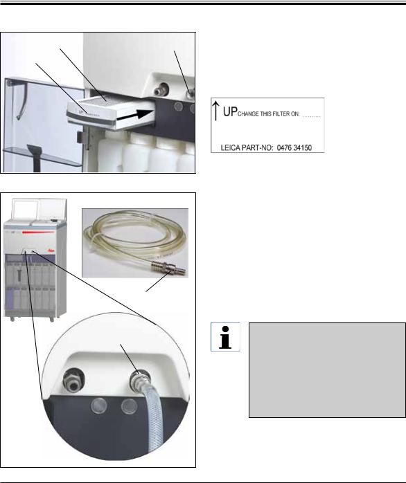
Active carbon filter
•Unpack the active carbon filter (13) and insert it (see Fig. 5).
When doing so, make sure that the filter is inserted with the correct side up.Note the
direction of the label (29) on the front of the filter - the arrow must be pointing upwards.
Remote fill / drain hose
•Connect the supplied remote fill/drain hose to the remote drain connection on the front of the instrument (refer Fig. 6).
•Important!
When inserting the hose into the drain opening (Fig. 5/6, 18), the connecting device (28) of the hose must engage with a clearly audible click.
If it is possible to set up the bulk container for filling and draining in the immediate vicinity of the instrument, the hose can be shortened so that it is easier to handle.
When shortening the hose, you can cut a V-shaped notch into the hose end to attain better flow.
Leica ASP200 S |
27 |
Loading...