


 Loading...
Instructions for use
Leica IP C -
Automated printing system for tissue cassettes
Leica IP C, V 1.9 RevD, English – 05/2013 Order No.: 14 0602 80101, RevD

Leica IP C
Automated printing system for tissue cassettes
Instructions for Use
Leica IP C
Order No. 14 0602 80101, RevD V 1.9 English – 05/2013
Always keep this manual with the instrument.
Read carefully before working with the instrument.

NOTE
The information, numerical data, notes and value judgments contained in this manual represent the current state of scientific knowledge and state-of-the-art technology as we understand it following thorough investigation in this field.
We are under no obligation to update the present manual according to the latest technical developments, nor to provide our customers with additional copies, updates etc. of this manual.
For erroneous statements, drawings, technical illustrations etc. contained in this manual we exclude liability as far as permissible according to the national legal system applicable in each individual case. In particular, no liability whatsoever is accepted for any financial loss or consequential damage caused by or related to compliance with statements or other information in this manual.
Statements, drawings, illustrations and other information as regards contents or technical details of the present manual are not to be considered as warranted characteristics of our products.
Leica Biosystems Nussloch GmbH Heidelberger Str. 17 - 19
69226 Nussloch Germany
Phone: +49 (0)62 24 143-0
Fax: +49 (0)62 24 143-268
Internet: http://www.LeicaBiosystems.com
These are determined only by the contract provisions agreed between ourselves and our customers.
Leica reserves the right to change technical specifications as well as manufacturing processes without prior notice. Only in this way is it possible to continuously improve the technology and manufacturing techniques used in our products. This document is protected under copyright laws. All copyrights of this document are retained by Leica Biosystems Nussloch GmbH.
Any reproduction of text and illustrations (or of any parts thereof) by means of print, photocopy, microfiche, web cam or other methods— including any electronic systems and media— requires express prior permission in writing by Leica Biosystems Nussloch GmbH.
For the instrument serial number and year of manufacture, please refer to the name plate at the back of the instrument.
© Leica Biosystems Nussloch GmbH
Leica IP C |
3 |

Table of contents
1. |
Important Information................................................................................................................ |
6 |
|
|
1.1 |
Symbols in the text and their meanings........................................................................................ |
6 |
|
1.1.1 |
Symbols on the transport packaging and their meanings...................................................... |
7 |
|
1.2 |
Qualification of personnel............................................................................................................ |
8 |
|
1.3 |
Intended use of instrument.......................................................................................................... |
8 |
|
1.4 |
Instrument type.............................................................................................................................. |
8 |
2. |
Safety............................................................................................................................................ |
9 |
|
|
2.1 |
Safety instructions........................................................................................................................ |
9 |
|
2.2 |
Warnings...................................................................................................................................... |
10 |
3. |
Instrument Components and Specifications....................................................................... |
12 |
|
|
3.1 |
Overview—instrument............................................................................................................... |
12 |
|
3.2 |
Technical data............................................................................................................................. |
14 |
|
3.3 |
Print specifications..................................................................................................................... |
16 |
|
3.3.1 |
Requirements for cassettes...................................................................................................... |
16 |
|
3.3.2 |
Print specifications..................................................................................................................... |
18 |
|
3.3.3 |
Printing bar code......................................................................................................................... |
19 |
|
3.3.4 |
Resistance against reagents..................................................................................................... |
21 |
4. |
Instrument Setup...................................................................................................................... |
22 |
|
|
4.1 |
Site requirements........................................................................................................................ |
22 |
|
4.2 |
Unpacking the Instrument......................................................................................................... |
22 |
|
4.2.1 |
Installing the printer.................................................................................................................... |
24 |
|
4.3 |
Standard delivery........................................................................................................................ |
25 |
|
4.4 |
Installing the manual unload station........................................................................................ |
26 |
|
4.5 |
Automated unload station (optional)........................................................................................ |
27 |
|
4.6 |
Installing/exchanging the flash bulb........................................................................................ |
28 |
|
4.7 |
Filling and inserting the magazines.......................................................................................... |
30 |
|
4.8 |
Electrical connection.................................................................................................................. |
33 |
|
4.9 |
Exchanging the cartridge........................................................................................................... |
34 |
|
4.10 |
Installing the printer driver........................................................................................................ |
38 |
4 |
Instructions for Use V 1.9 RevD – 05/2013 |

|
|
Table of contents |
|
|
|
|
|
5. |
Operation................................................................................................................................... |
41 |
|
|
5.1 |
Control panel functions.............................................................................................................. |
41 |
|
5.2 |
Display indications...................................................................................................................... |
46 |
|
5.3 |
Alarm functions........................................................................................................................... |
48 |
|
5.4 |
Printer driver settings................................................................................................................. |
49 |
6. |
Cleaning and Maintenance.................................................................................................... |
52 |
|
|
6.1 |
Cleaning the instrument............................................................................................................. |
52 |
|
6.2 |
Cleaning the print head.............................................................................................................. |
54 |
|
6.3 |
General maintenance................................................................................................................. |
55 |
|
6.4 |
Storing the printer....................................................................................................................... |
56 |
7. |
Troubleshooting........................................................................................................................ |
60 |
|
|
7.1 |
Malfunctions................................................................................................................................ |
60 |
|
7.2 |
Status messages......................................................................................................................... |
61 |
|
7.3 |
Error messages............................................................................................................................ |
62 |
|
7.4 |
Changing the flash bulb.............................................................................................................. |
65 |
|
7.5 |
Power failure................................................................................................................................ |
65 |
|
7.6 |
Replacing the secondary fuses................................................................................................ |
66 |
8. |
Warranty and Service.............................................................................................................. |
67 |
|
Leica IP C |
5 |
1.Important Information
1.1 Symbols in the text and their meanings
Warnings
appear in a gray box and are marked by a warning triangle  .
.
Notes,
i.e. important user information appear in a gray box and are marked by an information symbol  .
.
(5)Numbers in parentheses refer to item numbers in illustrations.
Function keys to be pressed on the LOAD touch screen are written in bold-print
capital letters.
Symbol for labeling electrical and electronic equipment in accordance with Section 7 of the German Electrical and Electronic Equipment Act (ElektroG). ElektroG is the law regarding the sale, return and environmentally sound disposal of electrical and electronic equipment.
CE labeling shows that the product corresponds to one or more applicable European directives.
Environmental protection symbol of the China RoHS directive.
The number in the symbol indicates the "Environment-friendly Use Period" of the product in years.
The symbol is used if a substance restricted in China is used in excess of the maximum permitted limit.
Inflammable solvents and reagents are identified using this symbol.
Manufacturer.
Instrument surfaces which become hot |
|
|
|
|
during operation are marked with this |
|
|
Observe the Instructions for Use! |
|
symbol. |
|
|
|
|
Avoid direct contact with these surfac- |
|
|
|
|
es - they may cause burns. |
|
|
|
|
|
|
|
|
Symbol for alternating current |
|
|
|
|
|
|
|
|
~ |
|
Warning – Dangerous |
electrical |
|
|
|
voltage. |
|
|
|
|
|
|
|
||
|
|
|
|
|
6 |
Instructions for Use V 1.9 RevD – 05/2013 |
1. Important Information
REF
SN
Order number for standard delivery or accessories.
Designates the serial number of the instrument.
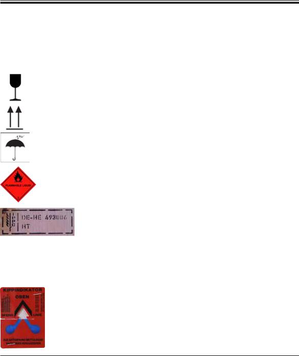
1.1.1 Symbols on the transport packaging and their meanings
The package contents are fragile and must be handled with care.
Indicates the correct upright position of the package.
The package must be kept in a dry environment.
Package labeling in accordance with German Hazardous Freight Ordinance Road and Rail (GGVSE)/European Agreement concerning the International Carriage of Dangerous Goods by Road (ADR) for transporting hazardous goods.
Class 3: "FLAMMABLE LIQUID" - Flammable liquid substance.
Example of labeling in accordance with IPPC IPPC symbol
Country code in accordance with ISO 3166, e.g. DE for Germany Regional identifier, e.g. HE for Hessen
Producer/treatment provider code, unique assigned number starting with 49
Treatment code, e.g. HT (heat treatment), MB (methyl bromide), and possibly DB (debarked)
Tip-n-Tell indicator to monitor whether the shipment has been transported and stored in upright position according to your requirements. With a pitch of 60° or more, the blue quartz sand flows into the arrow-shaped indicator window and sticks there permanently. Improper handling of the shipment is immediately detectable and can be proven definitively.
Leica IP C |
7 |

1.Important Information
1.2 Qualification of personnel
•TheLeicaIPCmaybeoperatedonlybytrained laboratory personnel.
•Alllaboratorypersonneldesignatedtooperate this instrument must read these Instructions for Use carefully and must be familiar with all technical features of the instrument before attempting to operate it.
1.3 Intended use of instrument
Leica IP C printer system for standard histology cassettes.
•The instrument has been designed for use in pathology, histology, cytology, toxicology and similar laboratories, and there only for printing tissue cassettes.
•Imprints of adequate quality and resistance to subsequent processing in tissue processors can only be guaranteed when using the cassettes and reagents specified in Chapter 3.3.
•The instrument must be used exclusively according to the instructions contained in these Instructions for Use.
Proper and intended use includes the observance of all instructions in the operating manual and compliance with all inspection and maintenance instructions.
Any other use of the instrument is considered improper!
1.4 Instrument type
All information provided in these Instructions for Use applies only to the instrument type indicated on the cover page.
A name plate indicating the instrument serial number is attached to the back of the instrument.
Fig. 1
Fig. 1 is provided as an example only and shows a valid nameplate for this instrument with the necessary information about instrument type and power requirement. The precise data for the various versions is specified in Chapter 3.2, "Technical data".
8 |
Instructions for Use V 1.9 RevD – 05/2013 |
2. Safety
The safety and caution notes in this chapter must be observed at all times.
Make sure to read these instructions, even if you are already familiar with the operation and use of other products.
2.1 Safety instructions
These Instructions for Use include important instructions and information related to the operating safety and maintenance of the instrument.
The Instructions for Use are an important part of the product, and must be read carefully prior to startup and use and must always be kept near the instrument.
This instrument has been built and tested in accordance with the safety regulations for electrical measuring, control, regulating and laboratory devices.
To maintain this condition and ensure safe operation, the user must observe all notes and warnings contained in these Instructions for Use.
These Instructions for Use must be appropriately supplemented as required by the existing regulations on accident prevention and environmental safety in the operator's country.
The protective devices on both instrument and accessories may neither be removed nor modified. Only authorized and qualified service personnel may access and repair the internal components of the instrument.
Use only the provided power cable - this must not be replaced with a different power cable. If the power plug does not fit in your socket, contact our service.
Residual risks
The instrument has been designed and constructed with the latest state-of-the-art technology and according to recognized standards and regulations with regard to safety technology. Operating or handling the instrument incorrectly can place the user or other personnel at risk of injury or can cause damage to the instrument or other property. The machine may be used only as intended and only if all of its safety features are in proper working condition. Malfunctions that impede safety must be remedied immediately.
For current information about applicable guidelines, please refer to the CE declaration of conformity and on our Internet site at:
http://www.LeicaBiosystems.com
Leica IP C |
9 |

2.Safety
2.2Warnings
The safety devices installed in this instrument by the manufacturer only constitute the basis for accident prevention. Operating the instrument safely is, above all, the responsibility of the owner, as well as the designated personnel who operate, service or repair the instrument.
To ensure trouble-free operation of the instrument, make sure to comply with the following instructions and warnings.
Warnings—Transport and Installation
•Once unpacked, the instrument may be transported only in an upright position.
•Do not expose the instrument to direct light (window, bulbs with strong light)!
•Only connect the instrument to a grounded power socket. Do not interfere with the grounding function by using an extension cord without a ground wire.
•Do not operate the instrument in rooms with explosion hazard.
•Condensation water may form in the instrument, if there is an extreme difference in temperature between the warehouse and the installation site and if air humidity is high at the same time. If this is the case, wait at least two hours before switching on the instrument. Failure to adhere to this waiting period may result in damage to the instrument.
Warnings—Markings on the instrument itself
•Markings on the instrument showing the warning triangle indicate that the correct operating instructions (as defined in these Instructions for Use) must be followed when operating or replacing the item marked.
•Failure to adhere to these instructions may lead to accidents causing personal injury and/or damage to the instrument or accessories or destroyed, unusable slides.
•Some instrument surfaces become hot during operation. They are marked with this warning
 label. Touching these surfaces may cause burns.
10 |
Instructions for Use V 1.9 RevD – 05/2013 |
2. Safety
Warnings—Instrument operation
•The instrument may be operated by trained laboratory personnel only. It must only be operated for the purpose of its designated use and according to the instructions contained in these Instructions for Use.
•The instrument is de-energized after disconnection of the power supply through the power cable (power supply circuit breaker) - in emergencies, disconnect the power plug.
•Do not touch the chute during operation. Risk of injury.
•Do not open the reflector flap of the flashlight while the instrument is ON—risk of burns and blinding.
•The device operator is obligated to conform to the local workplace limit values and to document them.
Warnings—Cleaning and maintenance
•Before any maintenance, switch off the instrument and unplug it from power supply.
•To clean the exterior surfaces, use a mild and ph-neutral commercial household cleaner. You may NOT use: Alcohol, cleaning materials containing alcohol (glass cleaner!), abrasives, or solvents containing acetone or xylene! The painted surfaces and the control panel of the instrument are not resistant to xylene or acetone!
•While working and during cleaning, no liquid may get into the interior of the instrument.
Leica IP C |
11 |

3.Instrument Components and Specifications
3.1 Overview—instrument
2.1
2
1
3
5
1- Basic instrument
2- Cassette magazines 2.1 - Magazine no. 1
3- Control panel
4 |
- |
Lid |
4 |
|
5 |
- |
Cover—cartridge slot |
||
6 |
||||
6 |
- |
Unload station (manual) |
||
Fig. 2 |
||||
|
|
|
|
|
12 |
|
|
Instructions for Use V 1.9 RevD – 05/2013 |

3. Instrument Components and Specifications
Front view without lid
|
|
|
|
|
11 |
|
|
|
6 |
3 |
12 |
|
2.1 -2.6 |
|
5 |
2 |
|
|
|
|
|
||
7 |
8 |
10 |
4 |
1 |
13 |
|
|
|
|
|
9 |
|
|
|
|
|
14 |
Fig. 3
2.1-2.6 - Magazine receptacles nos. 1 - 6
7- Drying module
8- Cover—flash bulb
9- Cassette carrier
10- Print head
11- Magazine holder
12- Feeding chute with cover
13- Transfer point: chute --> cassette carrier, with sensor
14- Location plate
15- External alarm jack
16- Socket for printer cable
Rear panel and electrical connections
17
15 
16
21 |
19 |
18 |
20 |
Fig. 4
17 - DIL switch
18 - Power supply connection
19 - Power switch
20 - Cleaning cartridge
21 - Secondary fuses
Attention for pos. 20.
The instrument is delivered with the storage cartridge installed!
Prior to operation, the cleaning cartridge must be exchanged for an ink cartridge - See "Exchanging the cartridge".
Leica IP C |
13 |

3.Instrument Components and Specifications
3.2 Technical data
General |
|
|
Approvals: |
The instrument-specific approval marks are located at the rear panel |
|
|
of the instrument, next to the name plate. |
|
Nominal supply voltages: |
|
100 to 120 V ~ +/- 10 % |
|
|
200 to 240 V ~ +/- 10 % |
Nominal frequency: |
|
50 to 60 Hz |
Power fuse: |
|
2x T 3.15 A L250 V |
Maximum power draw at 100 - 120 V: |
4.0 A |
|
Maximum power draw at 200 - 240 V: |
2.8 A |
|
Leakage current at 240 V/50 Hz: |
|
ca. 2.4 mA |
Nominal power: |
|
700 VA |
IEC 1010 classification: |
|
Protection class 1, pollution degree 2 |
|
|
Overvoltage installation category II |
Operating elevation: |
|
up to max. 2000 m NN |
A-weighted noise level: |
|
< 70 dB (A) |
IP protection class (IEC 60529) |
|
IP20 |
Climatic conditions for the operation of the instrument: |
|
|
Temperature: |
|
+15 °C to +30 °C |
Relative humidity: |
|
20 - 80 % - non-condensing |
Climatic conditions for the storage and transport of the packaged instrument: |
||
Storage temperature range: |
|
+5 °C to +40 °C |
Transport temperature range: |
|
-29 °C to +40 °C |
Relative humidity: |
|
10 - 85 % - non-condensing |
Dimensions and weight |
|
|
Dimensions of basic instrument |
|
|
Width x depth: |
|
475 x 650 mm |
Height with magazine: |
|
895 mm |
Dimensions with unload station connected |
|
|
Width x depth: |
|
548 x 650 mm |
Height with magazine: |
|
655 mm |
Basic instrument empty weight: |
|
approx. 28 kg |
Weight, packed: |
|
approx. 65 kg |
Unload station empty weight: |
|
approx. 14 kg |
Weight, packed: |
|
approx. 32 kg |
14 |
Instructions for Use V 1.9 RevD – 05/2013 |

3. Instrument Components and Specifications
Performance
Load capacity:
Printing speed 1: Printing batch jobs: Single-cassette printing:
Ink cartridge capacity 2: Flash bulb lifetime:
Printing
Print resolution 3:
Printing medium:
Print formats:
Pressure surfaces:
PC system requirements
IBM-compatible PC Processor clock frequency: Main memory (RAM):
Hard disk: CD-ROM drive 1 free serial port
Operating system:
up to 6 magazines,
up to 80 cassettes per magazine
15 cassettes/minute 10 s per cassette
approx. 60,000 printouts or 3.5 months approx. 150,000 flashes
360 x 360 dpi / 180 x 180 dpi, adjustable
Standard histology cassettes max. 28.9 x 80.0 mm (with lid) max. 6.2 mm high
Cassette 35°, cassette 45°
Cassette 35°: max. 28.2 x 8.0 mm Cassette 45°: max. 28.2 x 7.1 mm
min. 800 Mhz min. 256 MB min. 6 GB
Windows NT, Windows 2000, Windows XP Windows VISTA, Windows 7 (32 bit and 64 bit)
1) |
Average value—exact speed in each individual case depending on system configuration and |
|
software used. |
2) |
Average values are given; the exact number depends on the print density. |
3) |
Measured in addressable dots per inch |
Leica IP C |
15 |

3.Instrument Components and Specifications
3.3Print specifications
Only standard histology cassettes that are reliably inserted into the magazines can be used in
22 the Leica IP C.
23
22
Fig. 5
3.3.1 Requirements for cassettes
26
26
Fig. 6
24
25
Fig. 7
A wide variety of standard cassettes may be used in the IP C; however, the following restrictions must be observed:
•Suitableforprintingareallstandardcassettes without lids, of the following dimensions: Length without lid x Width = max. 41.3 x 28.9 mm
Length with lid x Width = max. 80.0 x 28.9 mm (Refer also to Technical Data, p. 11)
•Cassettes with lids attached have to be onepiece units (23); the lids must not just be linked to the body by a hinge.
•Cassettes with a flexible hinge cannot be used unless the lid is detached (25) or closed.
•Cassettes with a closed lid (26) must be checked to ensure that all four corners of the lid are firmly closed and flat.
•Cassettes with top-mounted lids (24) cannot be processed.
•For details on how to correctly insert the cassettes into the magazines, please refer to chapter 4.7.
16 |
Instructions for Use V 1.9 RevD – 05/2013 |

3. Instrument Components and Specifications
Recommended print media for the Leica IP C
The use of other print media may result in unsatisfactory print quality and/or jamming of slides/ cassettes during the printing process!
If the slides/cassettes you are currently using are not listed above, please contact your local Leica Microsystems’ representative.
The following cassettes have been successfully tested with the Leica IP C.
Cassette type |
Imprinting in Leica IP C |
|
|
Leica Jet I * |
without lid only |
|
|
Leica Jet II * |
with closed lid only |
|
|
Leica Jet III * |
with closed lid only |
|
|
Leica Jet IV |
ok |
|
|
Leica Jet V |
without lid only |
|
|
Leica Jet Bx |
with closed lid only |
|
|
Leica Jet I Bx |
with closed lid only |
|
|
Leica Jet II Bx |
ok |
|
|
Leica Jet III Bx |
ok |
|
|
Leica Jet IV Bx |
ok |
|
|
Leica Jet V Bx |
ok |
|
|
|
|
Sakura Tissue |
without lid only |
Tek MESH |
|
|
|
Sakura Tissue |
ok |
Tek II |
|
|
|
Sakura Tissue |
ok |
Tek III |
|
|
|
Cassette type |
Imprinting in Leica IP C |
|
|
Simport M 480 |
without lid only |
|
|
Simport M 492 |
with closed lid only |
|
|
Simport M 493 |
with closed lid only |
|
|
Simport M 502 |
ok |
|
|
Simport M 503 |
without lid only |
|
|
Simport M 505 |
ok |
|
|
Simport M 506 |
without lid only |
|
|
Simport M 507 |
with closed lid only |
|
|
|
|
Cellpath |
|
|
|
System II Hex * |
without lid only |
|
|
* Recommended for printing barcodes.
Cassettes of other manufacturers must be tested before use. The test must include the following steps:
Mechanical compatibility with the instrument. Imprint quality.
Resistance of the ink against the reagents with which the imprinted cassettes come into contact in the subsequent processes (refer also to Chapter 3.3.4).
Important!
Leica Biosystems assumes no responsibility whatsoever for any damages suffered as a consequence of imprints of poor quality or imprints made with non-reagent-resistant ink.
Leica IP C |
17 |

3.Instrument Components and Specifications
3.3.2 Print specifications
26 |
Printing area
The printing area parameters listed in the table below are defined in the printer driver.
|
Width |
|
Height |
|
|
|
|
|
|
Format |
Dots |
mm |
Dots |
mm |
|
|
|
|
|
Cassette 35° |
400 |
28,2 |
114 |
8,0 |
|
|
|
|
|
Cassette 45° |
400 |
28,2 |
100 |
7,1 |
|
|
|
|
|
Cassette type
There are two different cassette types, which have a different angle, and therefore a different printable area.
The angle (Fig. 9), measured from the bottom, can be 35° or 45°.
This must be taken into account in the settings for the printer driver (Chapter 5.4).
35°
45°
Fig. 9
Print resolution
The print head of the instrument has a preset resolution of 360 dpi in both directions (vertical and horizontal).
Each printed line has a maximum height of 128 dots.
This corresponds to a value of 9.03 mm.
In horizontal direction, the printable surface is limited only by the size of the object to be imprinted (Fig. 8).
The above values must be taken into consideration when defining the print area ("paper size") in the application you are going to print from.
Print quality
Quality and resolution of the imprints depend on:
•the cassette material and the dyes used to color the cassette material.
•the surface finish of the cassette imprint field
(26).
The final resolution of the imprints is not determined only by the resolution of the print head. If the cassette surface is not capable of 360 dpi resolution, "running" ink will lead to poor printing results. In such cases it is better to work at a lower resolution.
The printer driver allows you to change the resolution from 360 dpi to 180 dpi.
(For more information, refer to Chapter 5.4).
18 |
Instructions for Use V 1.9 RevD – 05/2013 |
3. Instrument Components and Specifications
3.3.3 Printing bar code
Printing readable bar codes depends on various factors that need to be taken into consideration in order to achieve results suitable for reliable and durable archiving. The main factors influencing the bar code results are:
•printer technology
•how the bar code is created
•the type of object being printed on
•the type of scanner used to read the bar code
Printer technology
•As a dot matrix printer, this device can handle information only in the form of dots printed or not printed. It is not possible to transmit bar code data or to select specific bar code types or use the printer to create and print the bar code required.
Creating bar codes
•Since there is only limited printing space on the cassettes, the bar code should not contain more information than necessary.
•You should use an error-checking code, which makes it easier for the bar code scanners to recognize possible errors. Some codes even support error correction.
•When calculating and creating bar code, always bear in mind the resolution of the printer.
The module size is the width of the smallest element of a bar code. Wider bars and spaces are calculated in multiples of the module size.
The module size always has to be an entire divisor of the printer resolution, as, due to the technology applied, only 'whole' dots can be printed. Reading errors may occur (even if the print appears to be crisp and correct), if, due to conversion, module width and resolution do not match any longer.
Data should never be printed as bar code only, but also as text (line of optical characters above or below the bar code), to ensure that no information is lost for the above reasons.
Leica IP C |
19 |
3.Instrument Components and Specifications
Requirements for bar code printing
The quality and readability of printed bar codes will depend on several factors that include:
•Texture and quality of the printable surface of the cassettes.
•Color of the selected cassette or slide
•Barcode style (2D).
•The number and types of characters required in the barcode.
•The quality and resolution capabilities of the bar code reader
As always, using Leica recommended print media will produce the highest quality print. However, it is highly recommended that any bar code solution be tested prior to implementation. Please check with your local representative for details on achieving the maximum number of characters with 2 D bar codes.
Bar code scanners
The scanning results obtained not only depend on the correct bar code creation and on the quality of the cassettes but also on the features of the bar code scanner used.
Features to bear in mind are:
•Reading tolerance:
difference between actual bar width and nominal module size.
•Light color:
the light color of the bar code scanner should be opposite (highly contrasting) to the color of the cassettes being used.
•Optical resolution:
must be better than the module size.
Depending on the application, the following features should also be considered:
•Maximum readable distance
•Maximum inclination angle
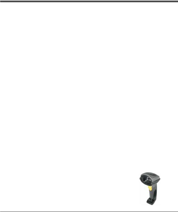
Leica has successfully tested the following readers:
Symbol DS 6707 Bar code Scanner
Fig. 10
20 |
Instructions for Use V 1.9 RevD – 05/2013 |
Loading...