


 MFC 400 Supplementary instructions
Signal converter for mass flowmeters
Description of Foundation Fieldbus interface
Electronic Revision: ER 1.0.x_
The documentation is only complete when used in combination with the relevant documentation for the flow sensor.
© KROHNE 11/2013 - 4003221901 - AD MFC 400 FF R01 en

|
CONTENTS |
MFC 400 |
|
|
|
||
|
|
|
|
1 Safety instructions |
3 |
|
1.1 |
Scope of the document..................................................................................................... |
3 |
1.2 |
Device description ............................................................................................................ |
3 |
2 Technical data |
4 |
|
2.1 |
Foundation Fieldbus data................................................................................................. |
4 |
3 Electrical connections |
5 |
|
3.1 |
Cable types ....................................................................................................................... |
5 |
3.2 |
Shielding and grounding .................................................................................................. |
5 |
3.3 |
Electrical connection of FOUNDATION Fieldbus ............................................................. |
6 |
3.4 |
Topology of FF networks .................................................................................................. |
7 |
4 Operation |
8 |
|
4.1 |
Settable functions............................................................................................................. |
8 |
4.2 |
Description of the FF block system.................................................................................. |
9 |
4.3 |
Used abbreviations ........................................................................................................... |
9 |
4.4 |
Resource Block (RB) ...................................................................................................... |
10 |
4.5 |
Analog Input Block (AI 1...6) ........................................................................................... |
33 |
4.6 |
FLOWTB (Flow Transducer Block)................................................................................. |
42 |
4.7 |
CONCTB (Concentration Transducer Block).................................................................. |
50 |
4.8 |
DIAGTB (Diagnose Transducer Block) ........................................................................... |
59 |
4.9 |
Integrator Block (IT) ....................................................................................................... |
69 |
4.10 Proportional Integral Derivative Block (PID) ............................................................... |
76 |
|
2 |
www.krohne.com |
11/2013 - 4003221901 - AD MFC 400 FF R01 en |
|
|
SAFETY INSTRUCTIONS 1 |
|
MFC 400 |
|
|
|
|
1.1 Scope of the document
These instructions are supplementary to the standard product documentation of the signal converter. The details depicted therein, in particular the safety information are valid and should be adhered to. The present supplementary instructions provide additional information for the devices when being operated and connected to a Foundation Fieldbus.
INFORMATION!
The present supplementary instruction for the signal converter with Foundation Fieldbus interface, plus the software with the DD and CCF files are included in our scope of supply, in addition to those items delivered for the standard device.
1.2 Device description
The mass flowmeters are designed exclusively to directly measure mass flow rates, product density and temperature as well to indirectly measure parameters such as the total volume and concentration of dissolved substances as well as the volume flow rate.
Your measuring device is supplied ready for operation. The factory settings for the operating data have been made in accordance with your order specifications.
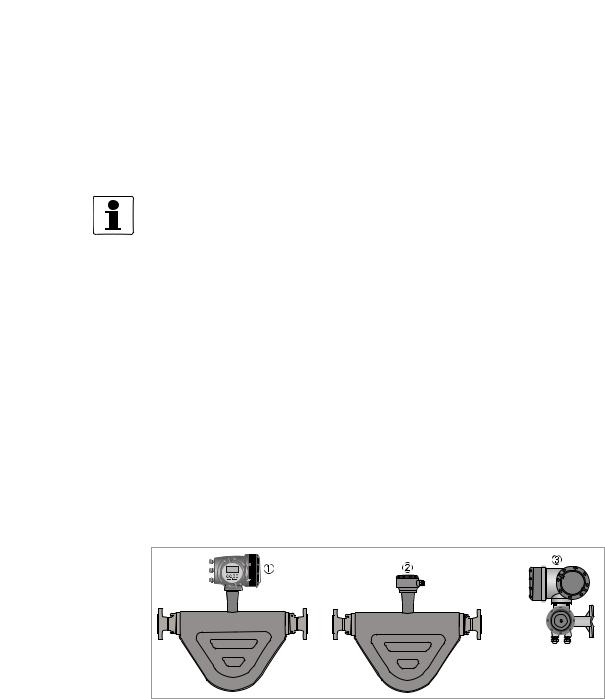
The following versions are available:
•Compact version (the signal converter is mounted directly on the measuring sensor)
•Remote version (electrical connection to the measuring sensor via field current and signal cable)
Figure 1-1: Device versions
1Compact version
2Measuring sensor with connection box
3Field housing
11/2013 - 4003221901 - AD MFC 400 FF R01 en |
www.krohne.com |
3 |

2 TECHNICAL DATA |
|
|
|
|
|
|
MFC 400 |
|
|||
|
|
|
|
||
2.1 Foundation Fieldbus data |
|||||
Description |
|
|
|
|
|
|
|
|
|
||
Type |
|
Ultrasonic flowmeter |
|
||
|
|
|
|
||
Physical layer |
|
Foundation Fieldbus protocol that agrees with IEC 61158-2 and FISCO model; |
|
|
|
|
|
galvanically isolated |
|
||
|
|
|
|
||
Communication standard |
|
H1 |
|
|
|
|
|
|
|
|
|
ITK version |
|
6.1 |
|
|
|
|
|
|
|
||
NAMUR 107 |
|
Supported within FF field diagnosis (FF-912) |
|
|
|
Data blocks |
|
|
|
|
|
|
|
|
|
||
Function blocks |
|
1 x Enhanced Resource Block (RB) |
|
||
|
|
|
|
||
|
|
1 x Customer Flow Transducer Block (FLOWTB) |
|
|
|
|
|
|
|
||
|
|
1 x Customer Concentration Transducer Block (CONCTB) |
|
|
|
|
|
|
|
||
|
|
1 x Customer Diagnose Transducer Block (DIAGTB) |
|
|
|
|
|
|
|
||
|
|
6 x Analog Input Block (AI) |
|
|
|
|
|
|
|
||
|
|
2 x Integrator Block (IT) |
|
|
|
|
|
|
|
||
|
|
1 x Proportional Integral Derivate Block (PID) |
|
|
|
|
|
|
|
||
Execution time |
|
Analog Input Block: 10 ms |
|
|
|
|
|
|
|
||
|
|
Integrator Block: 15 ms |
|
|
|
|
|
|
|
||
|
|
Proportional Integral Derivate Block: 25 ms |
|
|
|
Electrical connections |
|
|
|
|
|
|
|
|
|
||
Device power supply |
|
Not intrinsically safe: 9...32 VDC |
|
||
|
|
|
|
||
|
|
Intrinsically safe: 9...24 VDC |
|
|
|
|
|
|
|
||
Basic current |
|
10.5 mA |
|
|
|
|
|
|
|
||
Maximum error current |
|
16.5 mA (= basic current + error current = 10.5 mA + 6 mA) |
|
|
|
|
|
|
|
||
Start current after 10 ms |
|
14 mA |
|
|
|
|
|
|
|
||
Polarity sensitivity |
|
No |
|
|
|
|
|
|
|
||
Minimum cycle time |
|
250 ms |
|
|
|
|
|
|
|
|
|
4 |
www.krohne.com |
11/2013 - 4003221901 - AD MFC 400 FF R01 en |

|
|
ELECTRICAL CONNECTIONS 3 |
|
MFC 400 |
|
|
|
|
3.1 Cable types
The cable types are specified according to IEC 61158-2. Shielded cables offer the advantage of malfunction-free operation with adequate protection against electromagnetic influences, and make it possible to employ the full performance of the Foundation Fieldbus system.
Core cross-section |
0.8 mm2 or |
0.32 mm2 or |
0.13 mm2 or |
1.25 mm2 or |
|
AWG 18 |
AWG 22 |
AWG 26 |
AWG 16 |
|
|
|
|
|
Cable type |
A |
B |
C |
D |
|
|
|
|
|
|
twisted pair, |
individual or |
multiple twisted |
multiple non- |
|
individually |
multiple twisted |
pairs, without |
twisted cables, |
|
shielded |
pairs with overall |
shielding |
without shielding |
|
|
shield |
|
|
Max. length |
1900 m / 6200 ft |
1200 m / 3900 ft |
400 m / 1300 ft |
200 m / 650 ft |
incl. branch line |
|
|
|
|
In non-hazardous locations, a maximum of 32 field devices can be connected to the network. For more data, refer to the table that follows.
Number of devices |
Cable lengths for number of devices per branch line |
|||
|
|
|
|
|
|
1 device |
2 devices |
3 devices |
4 devices |
|
|
|
|
|
25...32 |
1 m / 3.3 ft |
1 m / 3.3 ft |
1 m / 3.3 ft |
1 m / 3.3 ft |
|
|
|
|
|
19...24 |
30 m / 100 ft |
1 m / 3.3 ft |
1 m / 3.3 ft |
1 m / 3.3 ft |
|
|
|
|
|
15...18 |
60 m / 200 ft |
30 m / 100 ft |
1 m / 3.3 ft |
1 m / 3.3 ft |
|
|
|
|
|
13...14 |
90 m / 300 ft |
60 m / 200 ft |
30 m / 100 ft |
1 m / 3.3 ft |
|
|
|
|
|
1..12 |
120 m / 400 ft |
90 m / 300 ft |
60 m / 200 ft |
30 m / 100 ft |
|
|
|
|
|
All bus segments must be fitted with a terminator at both ends.
3.2Shielding and grounding
•For optimum electromagnetic compatibility of systems it is extremely important that the system components, and particularly the bus cables connecting the components, are shielded and that such shields - if possible - form an unbroken cover.
•Hence, it follows that, for use in non-hazardous duty systems, the cable shield should be grounded as often as possible.
•In Ex systems an adequate equipotential bonding in the hazardous and non-hazardous location along the entire Fieldbus installation is strongly recommended. Multiple grounding of the shield is of advantage.
•In explosion-proof systems the shielding must at least be connected at one end of the cable.
•NAMUR NE 21 compliance is given, provided the above recommended cable types are used.
INFORMATION!
The use of twisted and shielded cables is strongly recommended, otherwise EMC protection of the signal converter cannot be assured.
11/2013 - 4003221901 - AD MFC 400 FF R01 en |
www.krohne.com |
5 |
3 ELECTRICAL CONNECTIONS |
|
|
MFC 400 |
|
|
|
|
|
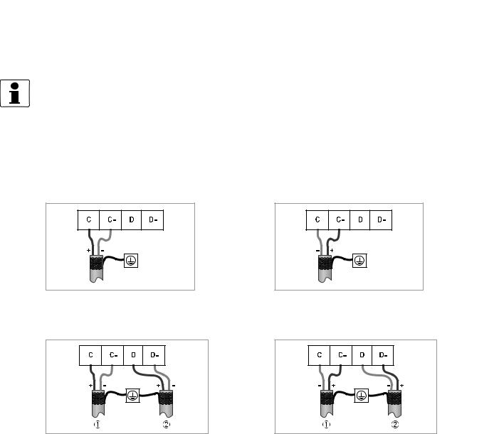
3.3 Electrical connection of FOUNDATION Fieldbus
INFORMATION!
The wiring between the device and the FOUNDATION Fieldbus cable is independant of polarity. The signal converter FOUNDATION Fieldbus interface will operate only if the additional power supply for the device is connected/available.
For a detailed description of the electrical connections please refer to the standard signal converter handbook.
Connection to a spur
or
Connection to a trunk
or
1 e.g. incoming data lines
2 e.g. outgoing data lines
6 |
www.krohne.com |
11/2013 - 4003221901 - AD MFC 400 FF R01 en |
|
|
ELECTRICAL CONNECTIONS 3 |
|
MFC 400 |
|
|
|
|
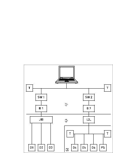
3.4 Topology of FF networks
An example of mixed topology of FF networks is shown in the following example.
Connection is best made via short branch cables and T connectors. This connection type makes it possible to connect and disconnect the devices without interrupting the bus or the communication.
1 |
2 |
3 |
B1+B2 |
D1-D3 |
D4-D6 |
I.S. |
JB |
PS |
T |
HSE network H1 bus
Intrisically safe, explosive area
Bridge = coupling element for H1 bus and HSE network
Device = field devices, own power supply, for non potentially explosive areas
Intrinsically safe devices, external power supply, for potentially explosive areas
Intrinsically safe barrier Junction box for field devices Power supply
Switch = connection of multiple HSE sub networks
Terminator
11/2013 - 4003221901 - AD MFC 400 FF R01 en |
www.krohne.com |
7 |

4 OPERATION |
MFC 400 |
|
4.1Settable functions
•For Foundation Fieldbus the totalizers of the signal converter are not available!
•The following tables describe only the menus, functions and parameters that are different between the standard signal converter and the Foundation Fieldbus signal converter.
•For the electrical connections of the outputs, inputs and all settings of functions that are not listed in the following tables refer to the standard product documentation.
No. |
Displayed text |
Description and settings |
|
|
|
A Quick Setup
A2 |
Tag |
Identifier for the measurement in a plant, appears in the display header |
|
|
(maximum 8 digits). |
|
|
|
|
|
Note: Only read, not changeable! |
|
|
|
B Test
B3.5 |
Foundation fieldbus |
Display information about Foundation fieldbus interface. |
|
|
|
C setup
C5.1.1 |
Tag |
Identifier for the measurement in a plant, appears in the display header |
|
|
(maximum 8 digits). |
|
|
|
|
|
Note: Only read, not changeable! |
|
|
|
C4 |
Totalizer |
Not available for Foundation Fieldbus devices! |
|
|
|
C5 |
I/O HART |
Not available for Foundation Fieldbus devices! |
|
|
|
C6.4 |
2nd Meas. Page |
In case of Foundation Fieldbus device, the second measurement page is |
|
|
meant to check the output values of the different function blocks. Only |
|
|
Foundation Fieldbus values can be selected here. The analogue inputs are |
|
|
shown with exactly the value, seen on the bus system. |
|
|
|
C6.4.1 |
1st Line Variable |
Select: AI1...6 analog inp. / PID / INT1..2 integrator |
|
|
|
C6.4.2 |
1st Line Format |
Fixed number of digits after the decimal point or automatic, where the |
|
|
number of digits is automatically adjusted to the available space. |
|
|
|
C6.4.3 |
2nd Line Variable |
Select: AI1...6 analog inp. / PID / INT1..2 integrator |
|
|
|
C6.4.4 |
2nd Line Format |
Fixed number of digits after the decimal point or automatic, where the |
|
|
number of digits is automatically adjusted to the available space. |
|
|
|
C6.4.5 |
3rd Line Variable |
Select: AI1...6 analog inp. / PID / INT1..2 integrator |
|
|
|
C6.4.6 |
3rd Line Format |
Fixed number of digits after the decimal point or automatic, where the |
|
|
number of digits is automatically adjusted to the available space. |
|
|
|
C6.8 |
Foundation Field |
- |
|
|
|
C6.8.1 |
Simulate |
Select: disabled / enabled |
|
|
|
C6.8.2 |
Information |
Display information about hardware and software versions, the calibration |
|
|
and test date of this interface. |
|
|
|
8 |
www.krohne.com |
11/2013 - 4003221901 - AD MFC 400 FF R01 en |

|
|
OPERATION 4 |
|
MFC 400 |
|
|
|
|
4.2 Description of the FF block system
The Foundation Fieldbus is a Local Area Network (LAN) for connecting field devices like sensors and actuators. One of the main benefits of Foundation Fieldbus is line saving in comparison to the traditional 4...20 mA technology.
The different device functions are implemented in a block-based scheme within a user application. In this block scheme, a distinction is made between the Resource Block, Transducer Block and Function Block.
1Resource Block (RB)
2Transducer Block (TB)
3Function Block (FB)
4Device FF communication
5Foundation Fieldbus
4.3Used abbreviations
AI |
Analogue Input Block |
|
BLK |
Block mode |
|
|
|
|
|
IT |
Integrator Block |
|
MAN |
Manual mode |
|
|
|
|
|
PID |
Proportional Integral Derivate Block |
|
Mix |
Mix mode (R, W and R/W) |
|
|
|
|
|
RB |
Resource Block |
|
Auto |
Automatic mode |
|
|
|
|
|
TB |
Transducer Block |
|
OOS |
Out Of Service mode |
|
|
|
|
|
R |
Read |
|
OD |
Object Directory |
|
|
|
|
|
W |
Write |
|
SP |
Set Point |
|
|
|
|
|
R/W |
Read and Write |
|
IV |
Initial Value |
|
|
|
|
|
|
|
|
PV |
Process Value (factory settings) |
|
|
|
|
|
11/2013 - 4003221901 - AD MFC 400 FF R01 en |
www.krohne.com |
9 |

4 OPERATION
4.4 Resource Block (RB)
MFC 400 
The following tables list the Resource Block parameters in alphabetical order.
It describes characteristics of the Fieldbus device (e.g. device name, serial number, etc.) and is not included in the functional tasks of the signal converter for FF.
The following tables contain short parameter description, factory settings (Initial Value (IV)) and possible settings.
Parameter |
Access |
Description and settings |
Initial Value |
DD name |
|
|
|
|
|
|
|
ALERT_KEY |
R/W |
The identification number of the plant unit. This information |
0 |
Alert Key |
|
may be used in the host for sorting alarms, etc. |
|
|
|
|
|
|
|
Setting: |
|
|
|
1...255 |
|
|
|
|
|
BLOCK_ERR |
R |
This parameter reflects the error status associated with the |
OOS (Out of |
Block Error |
|
hardware or software components associated with a block. It |
Service) |
|
|
is a bit string, so that multiple errors may be shown. |
|
|
|
|
|
|
|
Setting: |
|
|
|
• Other: Non-specific error active |
|
|
|
• Block Configuration: Error detected in block configuration |
|
|
|
• Link Configuration: Error detected in link configuration |
|
|
|
• Simulation Active: Simulation enabled in this block |
|
|
|
• Local Override: Output tracking of faultstate active |
|
|
|
• Device Fault State: Device faultstate set |
|
|
|
• Device Maintenance: Device needs maintenance soon |
|
|
|
• Input Failure: Process variable has bad status |
|
|
|
• Output Failure: Failure detected in output hardware |
|
|
|
• Memory Failure: Memory error detected |
|
|
|
• Lost Static Data: Static parameters cannot be recovered |
|
|
|
• Lost NV Data: Non-volatile parameters cannot be recovered |
|
|
|
• Readback Check: Failure detected in READBACK |
|
|
|
• Maintenance Needed: Device NEEDS maintenance NOW |
|
|
|
• Power Up: Recovery from power failure |
|
|
|
• Out Of Service: Block actual mode is out of service |
|
|
|
|
|
MODE_BLK |
Mix |
The actual, target, permitted and normal modes of the block. |
- |
Block Mode |
|
|
|
TARGET |
R/W |
This is the mode requested by the operator. Only one mode |
OOS |
Target |
|
from those allowed by the permitted mode parameter may be |
|
|
|
requested. |
|
|
|
Setting: |
|
|
|
Auto / OOS |
|
|
|
|
|
ACTUAL |
R |
This is the current mode of the block, which may differ from |
OOS |
Actual |
|
the target based on operating conditions. Its value is |
|
|
|
calculated as part of block execution. |
|
|
|
|
|
|
|
Setting: |
|
|
|
Auto / OOS |
|
|
|
|
|
PERMITTED |
R/W |
Defines the modes which are allowed for an instance of the |
Auto |
Permitted |
|
block. The permitted mode is configured based on application |
OOS |
|
|
requirement. |
|
|
|
|
|
|
|
Setting: |
|
|
|
Auto / OOS |
|
|
|
|
|
10 |
www.krohne.com |
11/2013 - 4003221901 - AD MFC 400 FF R01 en |
|
|
OPERATION 4 |
|
MFC 400 |
|
|
|
|
Parameter |
Access |
Description and settings |
Initial Value |
DD name |
|
|
|
|
|
|
|
NORMAL |
R/W |
This is the mode which the block should be set to during |
Auto |
Normal |
|
normal operating conditions. |
|
|
|
|
|
|
|
Setting: |
|
|
|
Auto / OOS |
|
|
|
|
|
ST_REV |
R |
The revision level of the static data associated with the |
0 |
Static Revision |
|
function block. The revision value will be incremented each |
|
|
|
time a static parameter value in the block is changed. |
|
|
|
|
|
|
|
Setting: |
|
|
|
0...65535 |
|
|
|
|
|
STRATEGY |
R/W |
The strategy field can be used to identify grouping of blocks. |
0 |
Strategy |
|
This data is not checked or processed by the block. |
|
|
|
|
|
|
|
Setting: |
|
|
|
0...65535 |
|
|
|
|
|
TAG_DESC |
R/W |
The user description of the intended application of the block. |
blanks |
Tag Description |
|
|
|
|
Setting: |
|
|
|
|
|
|
|
|
≤32 digits |
|
|
|
|
|
ACK_OPTION |
R/W |
Selection of whether alarms associated with the function |
Uninitialized |
Acknowledge Option |
|
block will be automatically acknowledged. |
|
|
|
|
|
|
|
Setting: |
|
|
|
Disc Alm Auto Ack / Blk Alm Auto Ack / Fail Alm Auto Ack / Off |
|
|
|
Spec Alm Auto Ack / Maint Alm Auto Ack / Check Alm Auto Ack |
|
|
|
|
|
ALARM_SUM |
R |
The current alert status, unacknowledged states, unreported |
- |
Alarm Summary |
|
states and disabled states of the alarms associated with the |
|
|
|
function block. |
|
|
|
|
|
Current |
R |
The active status of each alarm. |
Uninitialized |
|
|
|
|
|
|
Setting: |
|
|
|
Discrete Alarm / Block Alarm / Fail Alarm / Off Spec Alarm / |
|
|
|
Maintenance Alarm / Check Alarm |
|
|
|
|
|
Unacknowledged |
R |
The unacknowledged state of each alarm. |
Uninitialized |
|
|
|
|
|
|
Setting: |
|
|
|
Disc Alm Unack / Block Alm Unack / Fail Alm Unack / Off Spec |
|
|
|
Alm Unack / Maint Alm Unack / Check Alm Unack |
|
Unreported |
R |
The unreported status of each alarm. |
Uninitialized |
|
|
|
|
|
|
Setting: |
|
|
|
Disc Alm Unrep / Block Alm Unrep / Fail Alm Unrep / Off Spec |
|
|
|
Alm Unrep / Maint Alm Unrep / Check Alm Unrep |
|
Disabled |
R/W |
The disabled state of each alarm. |
Uninitialized |
|
|
|
|
|
|
Setting: |
|
|
|
Disc Alm Disabled / Block Alm Disabled / Fail Alm Disabled / |
|
|
|
Off Spec Alm Disabled / Maint Alm Disabled / Check Alm |
|
|
|
Disabled |
|
BLOCK_ALM |
|
The block alarm is used for all configuration, hardware, |
- |
Block Alarm |
|
connection failure or system problems in the block. The cause |
|
|
|
of the alert is entered in the subcode field. The first alert to |
|
|
|
become active will set the "Active" status in the "Status" |
|
|
|
attribute. As soon as the "Unreported" status is cleared by the |
|
|
|
alert reporting task, another block alert may be reported |
|
|
|
without clearing the "Active" status, if the subcode has |
|
|
|
changed. |
|
|
|
|
|
Unacknowledged |
R/W |
A discrete enumeration which is set to "Unacknowledged" |
Uninitialized |
|
|
when an alarm occurs, and set to "Acknowledged" by a write |
|
|
|
from a human interface device or other entity which can |
|
|
|
acknowledge that the alarm/event has been noticed. |
|
|
|
|
|
|
|
Setting: |
|
|
|
Uninitialized / Acknowledged / Unacknowledged |
|
|
|
|
|
11/2013 - 4003221901 - AD MFC 400 FF R01 en |
www.krohne.com |
11 |

4 OPERATION |
|
|
MFC 400 |
|
||
|
|
|
|
|
|
|
Parameter |
|
Access |
Description and settings |
Initial Value |
|
|
DD name |
|
|
|
|
|
|
|
|
|
|
|
|
|
Alarm State |
|
R |
A discrete enumeration which gives an indication of whether |
Uninitialized |
|
|
|
|
|
the alert is active and whether it has been reported. |
|
|
|
|
|
|
|
|
|
|
|
|
|
Setting: |
|
|
|
|
|
|
Uninitialized / Clear - reported / Clear - not reported / Active - |
|
|
|
|
|
|
reported / Active - not reported |
|
|
|
|
|
|
|
|
|
|
Time Stamp |
|
R |
The time when evaluation of the block was started and a |
Uninitialized |
|
|
|
|
|
change in alarm/event state was detected that is unreported. |
|
|
|
|
|
|
The time stamp value will be maintained constant until alert |
|
|
|
|
|
|
confirmation has been received - even if another change of |
|
|
|
|
|
|
state occurs. |
|
|
|
|
|
|
|
|
|
|
|
|
|
Setting: |
|
|
|
|
|
|
MM / DD / YY (Month / Day / Year) |
|
|
|
|
|
|
HH:MM:SS (Hour:Minute:Second) |
|
|
|
|
|
|
|
|
|
|
Subcode |
|
R |
An enumeration specifying the cause of the alert to be |
Other |
|
|
|
|
|
reported. |
|
|
|
|
|
|
|
|
|
|
|
|
|
Setting: |
|
|
|
|
|
|
Other / Block Configuration / Link Configuration / Simulation |
|
|
|
|
|
|
Active / Local Override / Device Fault State / Device |
|
|
|
|
|
|
Maintenance / Input Failure / Output Failure / Memory |
|
|
|
|
|
|
Failure / Lost Static Data / Lost NV Data / Readback Check / |
|
|
|
|
|
|
Maintenance Needed / Power Up / Out Of Service |
|
|
|
|
|
|
|
|
|
|
Value |
|
R |
The value of the associated parameter at the time the alert |
0 |
|
|
|
|
|
was detected. |
|
|
|
|
|
|
|
|
|
|
|
|
|
Setting: |
|
|
|
|
|
|
0...255 |
|
|
|
|
|
|
|
|
|
|
CLR_FSTATE |
|
R/W |
Writing a "Clear" to this parameter will clear the device fault |
Off |
|
|
Clear Fault State |
|
|
state if the field condition, if any, has cleared. |
|
|
|
|
|
|
|
|
|
|
|
|
|
Setting: |
|
|
|
|
|
|
Uninitialized / Off / Clear |
|
|
|
|
|
|
|
|
|
|
CONFIRM_TIME |
|
R/W |
The minimum time between retries of alert reports. |
640000 |
|
|
Confirm Time |
|
|
|
|
|
|
|
|
Setting: |
|
|
|
|
|
|
|
|
|
|
|
|
|
|
0...4294967295 in [1/32 ms] |
|
|
|
|
|
|
|
|
|
|
CYCLE_SEL |
|
R/W |
Used to select the block execution method for this resource. |
Uninitialized |
|
|
Cycle Selection |
|
|
|
|
|
|
|
|
Setting: |
|
|
|
|
|
|
|
|
|
|
|
|
|
|
Scheduled / Block execution |
|
|
|
|
|
|
|
|
|
|
CYCLE_TYPE |
|
R |
Identifies the block execution methods available for this |
Scheduled |
|
|
Cycle Type |
|
|
resource. |
Block execution |
|
|
|
|
|
Setting: |
|
|
|
|
|
|
Scheduled / Block execution |
|
|
|
DD_RESOURCE |
|
R |
String identifying the tag of the resource which contains the |
blanks |
|
|
DD Resource |
|
|
Device Description for this resource. |
|
|
|
|
|
|
Setting: |
|
|
|
|
|
|
≤ 32 digits |
|
|
|
DD_REV |
|
R |
Revision of the DD associated with the resource - used by an |
Dependent on |
|
|
DD Revision |
|
|
interface device to locate the DD file for the resource. |
device version. |
|
|
|
|
|
Setting: |
|
|
|
|
|
|
Dependent on device version. |
|
|
|
|
|
|
|
|
|
|
DEV_REV |
|
R |
Manufacturer revision number associated with the resource - |
Dependent on |
|
|
Device Revision |
|
|
used by an interface device to locate the DD file for the |
device version. |
|
|
|
|
|
resource. |
|
|
|
|
|
|
|
|
|
|
|
|
|
Setting: |
|
|
|
|
|
|
Dependent on device version. |
|
|
|
|
|
|
|
|
|
|
12 |
www.krohne.com |
11/2013 - 4003221901 - AD MFC 400 FF R01 en |

|
|
OPERATION 4 |
|
MFC 400 |
|
|
|
|
Parameter |
Access |
Description and settings |
Initial Value |
DD name |
|
|
|
|
|
|
|
DEV_TYPE |
R |
Manufacturer's model number associated with the resource - |
MFC400 |
Device Type |
|
used by interface devices to locate the DD file for the |
|
|
|
resource. |
|
|
|
|
|
|
|
Setting: |
|
|
|
MFC400 |
|
|
|
|
|
FAULT_STATE |
R |
Condition set by loss of communication to an output block, |
Clear |
Fault State |
|
failure promoted to an output block or a physical contact. |
|
|
|
When fault state condition is set, then output function blocks |
|
|
|
will perform their "FSTATE" actions. |
|
|
|
|
|
|
|
Setting: |
|
|
|
Uninitialized / Off / Clear |
|
|
|
|
|
FD_CHECK_ACTIVE |
R |
This parameter reflects the error conditions that are being |
Uninitialized |
Check Active |
|
detected as active as selected for this category. It is a bit |
|
|
|
string, so that multiple conditions may be shown. See section |
|
|
|
2.9. |
|
|
|
|
|
|
|
Setting: |
|
|
|
(00) Check / (01) Electronics : Operation Info / |
|
|
|
(02) Config: NoMeas.Value / (08) Electronics : Power Fail / |
|
|
|
(09) Process: System Control / (10) Configuration : Totaliser / |
|
|
|
(11) Process : Signal Low / (12) Process : 2 Phase Flow / |
|
|
|
(13) Process : Signal Search / (14) Electronics : IO |
|
|
|
Connection / (15) Process : Current input / (16) M Process / |
|
|
|
(17) M Configuration / (18) M Electronics / (19) M Sensor / |
|
|
|
(20) S Process / (21) S Configuration / (22) S Electronics / |
|
|
|
(23) S Sensor / (24) C Process / (25) C Configuration / |
|
|
|
(26) C Electronics / (27) C Sensor / (28) F Process / |
|
|
|
(29) F Configuration / (30) F Electronics / (31) F Sensor |
|
|
|
|
|
FD_CHECK_ALM |
|
This parameter is used primarily to broadcast a change in the |
- |
Check Alarm |
|
associated active conditions, which are not masked, for this |
|
|
|
alarm category to a Host System. |
|
|
|
|
|
Unacknowledged |
R/W |
A discrete enumeration which is set to "Unacknowledged" |
Uninitialized |
|
|
when an alarm occurs, and set to "Acknowledged" by a write |
|
|
|
from a human interface device or other entity which can |
|
|
|
acknowledge that the alarm/event has been noticed. |
|
|
|
|
|
|
|
Setting: |
|
|
|
Uninitialized / Acknowledged / Unacknowledged |
|
|
|
|
|
Alarm State |
R |
A discrete enumeration which gives an indication of whether |
Uninitialized |
|
|
the alert is active and whether it has been reported. |
|
|
|
|
|
|
|
Setting: |
|
|
|
Uninitialized / Clear - reported / Clear - not reported / |
|
|
|
Active - reported / Active - not reported |
|
|
|
|
|
Time Stamp |
R |
The time when evaluation of the block was started and a |
Uninitialized |
|
|
change in alarm/event state was detected that is unreported. |
|
|
|
The time stamp value will be maintained constant until alert |
|
|
|
confirmation has been received - even if another change of |
|
|
|
state occurs. |
|
|
|
|
|
|
|
Setting: |
|
|
|
MM / DD / YY (Month / Day / Year) |
|
|
|
HH:MM:SS (Hour:Minute:Second) |
|
|
|
|
|
Subcode |
R |
An enumeration specifying the cause of the alert to be |
Other |
|
|
reported. |
|
|
|
Setting: |
|
|
|
Other / Block Configuration / Link Configuration / Simulation |
|
|
|
Active / Local Override / Device Fault State / Device |
|
|
|
Maintenance / Input Failure / Output Failure / Memory |
|
|
|
Failure / Lost Static Data / Lost NV Data / Readback Check / |
|
|
|
Maintenance Needed / Power Up / Out Of Service |
|
Value |
R |
The value of the associated parameter at the time the alert |
- |
|
|
was detected. |
|
11/2013 - 4003221901 - AD MFC 400 FF R01 en |
www.krohne.com |
13 |

4 OPERATION |
|
|
|
MFC 400 |
|
||
|
|
|
|
|
|
|
|
Parameter |
|
Access |
Description and settings |
Initial Value |
|
|
|
DD name |
|
|
|
|
|
|
|
|
|
|
|
|
|
|
|
FD_CHECK_MAP |
|
R/W |
This parameter enables or disables conditions to be detected |
(24) (25) (26) (27) |
|
|
|
Check Map |
|
|
as active for this alarm category. |
(9) |
|
|
|
|
|
|
|
|
|
|
|
|
|
|
Setting: |
|
|
|
|
|
|
|
(00) |
Check / (01) Electronics : Operation Info / |
|
|
|
|
|
|
(02) |
Config: NoMeas.Value / (08) Electronics : Power Fail / |
|
|
|
|
|
|
(09) |
Process: System Control / (10) Configuration : Totaliser / |
|
|
|
|
|
|
(11) |
Process : Signal Low / (12) Process : 2 Phase Flow / |
|
|
|
|
|
|
(13) |
Process : Signal Search / (14) Electronics : IO |
|
|
|
|
|
|
Connection / (15) Process : Current input / (16) M Process / |
|
|
|
|
|
|
|
(17) |
M Configuration / (18) M Electronics / (19) M Sensor / |
|
|
|
|
|
|
(20) |
S Process / (21) S Configuration / (22) S Electronics / |
|
|
|
|
|
|
(23) |
S Sensor / (24) C Process / (25) C Configuration / |
|
|
|
|
|
|
(26) |
C Electronics / (27) C Sensor / (28) F Process / |
|
|
|
|
|
|
(29) |
F Configuration / (30) F Electronics / (31) F Sensor |
|
|
|
|
|
|
|
|
|
|
|
FD_CHECK_MASK |
|
R/W |
This parameter allows the user to suppress any single or |
(24) (25) (26) (27) |
|
|
|
Check Mask |
|
|
multiple conditions that are active, in this category, from |
(9) |
|
|
|
|
|
|
being broadcast to the host through the alarm parameter. |
|
|
|
|
|
|
|
|
|
|
|
|
|
|
|
Setting: |
|
|
|
|
|
|
|
(00) |
Check / (01) Electronics : Operation Info / |
|
|
|
|
|
|
(02) |
Config: NoMeas.Value / (08) Electronics : Power Fail / |
|
|
|
|
|
|
(09) |
Process: System Control / (10) Configuration : Totaliser / |
|
|
|
|
|
|
(11) |
Process : Signal Low / (12) Process : 2 Phase Flow / |
|
|
|
|
|
|
(13) |
Process : Signal Search / (14) Electronics : IO |
|
|
|
|
|
|
Connection / (15) Process : Current input / (16) M Process / |
|
|
|
|
|
|
|
(17) |
M Configuration / (18) M Electronics / (19) M Sensor / |
|
|
|
|
|
|
(20) |
S Process / (21) S Configuration / (22) S Electronics / |
|
|
|
|
|
|
(23) |
S Sensor / (24) C Process / (25) C Configuration / |
|
|
|
|
|
|
(26) |
C Electronics / (27) C Sensor / (28) F Process / |
|
|
|
|
|
|
(29) |
F Configuration / (30) F Electronics / (31) F Sensor |
|
|
|
|
|
|
|
|
|
|
|
FD_CHECK_PRI |
|
R/W |
This parameter allows the user to specify the priority of this |
0 |
|
|
|
Check Priority |
|
|
alarm category. |
|
|
|
|
|
|
|
|
|
|
|
|
|
|
|
Setting: |
|
|
|
|
|
|
|
0...15 |
|
|
|
|
|
|
|
|
|
|
|
|
FD_FAIL_ACTIVE |
|
R |
This parameter reflects the error conditions that are being |
Uninitialized |
|
|
|
Fail Active |
|
|
detected as active as selected for this category. It is a bit |
|
|
|
|
|
|
|
string, so that multiple conditions may be shown. See section |
|
|
|
|
|
|
|
2.9. |
|
|
|
|
|
|
|
|
|
|
|
|
|
|
|
Setting: |
|
|
|
|
|
|
|
(00) |
Check / (01) Electronics : Operation Info / |
|
|
|
|
|
|
(02) |
Config: NoMeas.Value / (08) Electronics : Power Fail / |
|
|
|
|
|
|
(09) |
Process: System Control / (10) Configuration : Totaliser / |
|
|
|
|
|
|
(11) |
Process : Signal Low / (12) Process : 2 Phase Flow / |
|
|
|
|
|
|
(13) |
Process : Signal Search / (14) Electronics : IO |
|
|
|
|
|
|
Connection / (15) Process : Current input / (16) M Process / |
|
|
|
|
|
|
|
(17) |
M Configuration / (18) M Electronics / (19) M Sensor / |
|
|
|
|
|
|
(20) |
S Process / (21) S Configuration / (22) S Electronics / |
|
|
|
|
|
|
(23) |
S Sensor / (24) C Process / (25) C Configuration / |
|
|
|
|
|
|
(26) |
C Electronics / (27) C Sensor / (28) F Process / |
|
|
|
|
|
|
(29) |
F Configuration / (30) F Electronics / (31) F Sensor |
|
|
|
|
|
|
|
|
|
|
|
FD_FAIL_ALM |
|
|
This parameter is used primarily to broadcast a change in the |
- |
|
|
|
Fail Diagnostic Alarm |
|
|
associated active conditions, which are not masked, for this |
|
|
|
|
|
|
|
alarm category to a Host System. |
|
|
|
|
|
|
|
|
|
|
|
|
Unacknowledged |
|
R/W |
A discrete enumeration which is set to "Unacknowledged" |
Uninitialized |
|
|
|
|
|
|
when an alarm occurs, and set to "Acknowledged" by a write |
|
|
|
|
|
|
|
from a human interface device or other entity which can |
|
|
|
|
|
|
|
acknowledge that the alarm/event has been noticed. |
|
|
|
|
|
|
|
|
|
|
|
|
|
|
|
Setting: |
|
|
|
|
|
|
|
Uninitialized / Acknowledged / Unacknowledged |
|
|
|
|
|
|
|
|
|
|
|
|
14 |
www.krohne.com |
11/2013 - 4003221901 - AD MFC 400 FF R01 en |

|
|
OPERATION 4 |
|
MFC 400 |
|
|
|
|
Parameter |
Access |
Description and settings |
Initial Value |
|
DD name |
|
|
|
|
|
|
|
|
|
Alarm State |
R |
A discrete enumeration which gives an indication of whether |
Uninitialized |
|
|
|
the alert is active and whether it has been reported. |
|
|
|
|
|
|
|
|
|
Setting: |
|
|
|
|
Uninitialized / Clear - reported / Clear - not reported / Active - |
|
|
|
|
reported / Active - not reported |
|
|
|
|
|
|
|
Time Stamp |
R |
The time when evaluation of the block was started and a |
Uninitialized |
|
|
|
change in alarm/event state was detected that is unreported. |
|
|
|
|
The time stamp value will be maintained constant until alert |
|
|
|
|
confirmation has been received - even if another change of |
|
|
|
|
state occurs. |
|
|
|
|
|
|
|
|
|
Setting: |
|
|
|
|
MM / DD / YY (Month / Day / Year) |
|
|
|
|
HH:MM:SS (Hour:Minute:Second) |
|
|
|
|
|
|
|
Subcode |
R |
An enumeration specifying the cause of the alert to be |
Other |
|
|
|
reported. |
|
|
|
|
|
|
|
|
|
Setting: |
|
|
|
|
Other / Block Configuration / Link Configuration / Simulation |
|
|
|
|
Active / Local Override / Device Fault State / Device |
|
|
|
|
Maintenance / Input Failure / Output Failure / Memory |
|
|
|
|
Failure / Lost Static Data / Lost NV Data / Readback Check / |
|
|
|
|
Maintenance Needed / Power Up / Out Of Service |
|
|
|
|
|
|
|
Value |
R |
The value of the associated parameter at the time the alert |
- |
|
|
|
was detected. |
|
|
|
|
|
|
|
FD_FAIL_MAP |
R/W |
This parameter enables or disables conditions to be detected |
(28) (29) (30) (31) |
|
Fail Map |
|
as active for this alarm category. |
(13) |
|
|
|
|
|
|
|
|
Setting: |
|
|
|
|
(00) |
Check / (01) Electronics : Operation Info / |
|
|
|
(02) |
Config: NoMeas.Value / (08) Electronics : Power Fail / |
|
|
|
(09) |
Process: System Control / (10) Configuration : Totaliser / |
|
|
|
(11) |
Process : Signal Low / (12) Process : 2 Phase Flow / |
|
|
|
(13) |
Process : Signal Search / (14) Electronics : IO |
|
|
|
Connection / (15) Process : Current input / (16) M Process / |
|
|
|
|
(17) |
M Configuration / (18) M Electronics / (19) M Sensor / |
|
|
|
(20) |
S Process / (21) S Configuration / (22) S Electronics / |
|
|
|
(23) |
S Sensor / (24) C Process / (25) C Configuration / |
|
|
|
(26) |
C Electronics / (27) C Sensor / (28) F Process / |
|
|
|
(29) |
F Configuration / (30) F Electronics / (31) F Sensor |
|
|
|
|
|
|
FD_FAIL_MASK |
R/W |
This parameter allows the user to suppress any single or |
(28) (29) (30) (31) |
|
Fail Mask |
|
multiple conditions that are active, in this category, from |
(13) |
|
|
|
being broadcast to the host through the alarm parameter. |
|
|
|
|
|
|
|
|
|
Setting: |
|
|
|
|
(00) |
Check / (01) Electronics : Operation Info / |
|
|
|
(02) |
Config: NoMeas.Value / (08) Electronics : Power Fail / |
|
|
|
(09) |
Process: System Control / (10) Configuration : Totaliser / |
|
|
|
(11) |
Process : Signal Low / (12) Process : 2 Phase Flow / |
|
|
|
(13) |
Process : Signal Search / (14) Electronics : IO |
|
|
|
Connection / (15) Process : Current input / (16) M Process / |
|
|
|
|
(17) |
M Configuration / (18) M Electronics / (19) M Sensor / |
|
|
|
(20) |
S Process / (21) S Configuration / (22) S Electronics / |
|
|
|
(23) |
S Sensor / (24) C Process / (25) C Configuration / |
|
|
|
(26) |
C Electronics / (27) C Sensor / (28) F Process / |
|
|
|
(29) |
F Configuration / (30) F Electronics / (31) F Sensor |
|
|
|
|
|
|
FD_FAILK_PRI |
R/W |
This parameter allows the user to specify the priority of this |
0 |
|
Fail Priority |
|
alarm category. |
|
|
|
|
|
|
|
|
|
Setting: |
|
|
|
|
0...15 |
|
|
|
|
|
|
|
11/2013 - 4003221901 - AD MFC 400 FF R01 en |
www.krohne.com |
15 |

4 OPERATION |
|
|
MFC 400 |
|
||
|
|
|
|
|
|
|
Parameter |
|
Access |
Description and settings |
Initial Value |
|
|
DD name |
|
|
|
|
|
|
|
|
|
|
|
|
|
FD_EXTENDED_ |
|
R |
An optional parameter to allow the user finer detail on |
Uninitialized |
|
|
ACTIVE_1 |
|
|
conditions causing an active condition in the FD_*_ACTIVE |
|
|
|
FD_EXTENDED_ |
|
|
parameter. |
|
|
|
ACTIVE_1 |
|
|
|
|
|
|
|
|
Setting: |
|
|
|
|
|
|
|
|
|
|
|
|
|
|
(01) Optical Interf. Active / (02) Disp. 2 Overrange / |
|
|
|
|
|
|
(03) Disp. 1 Overrange / (06) RB is set to OOS / |
|
|
|
|
|
|
(07) Fieldbus No Connection / (11) Status Out B Active / |
|
|
|
|
|
|
(13) Status Out A Active / (14) Control In B Active / |
|
|
|
|
|
|
(15) Control In A Active / (31) Zero Calibr. Running |
|
|
|
|
|
|
|
|
|
|
FD_EXTENDED_ |
|
R |
An optional parameter to allow the user finer detail on |
Uninitialized |
|
|
ACTIVE_2 |
|
|
conditions causing an active condition in the FD_*_ACTIVE |
|
|
|
FD_EXTENDED_ |
|
|
parameter. |
|
|
|
ACTIVE_2 |
|
|
|
|
|
|
|
|
Setting: |
|
|
|
|
|
|
|
|
|
|
|
|
|
|
(20) Disp. 2 no measure values / (21) Dsp. 1 no measure |
|
|
|
|
|
|
values / (28) IO B No Value for Binary Output / |
|
|
|
|
|
|
(29) IO B No Value for Current Output / (30) IO A No Value for |
|
|
|
|
|
|
Binary Output / (31) IO A No Value for Current Output |
|
|
|
|
|
|
|
|
|
|
FD_EXTENDED_ |
|
R |
An optional parameter to allow the user finer detail on |
Uninitialized |
|
|
ACTIVE_3 |
|
|
conditions causing an active condition in the FD_*_ACTIVE |
|
|
|
FD_EXTENDED_ |
|
|
parameter. |
|
|
|
ACTIVE_3 |
|
|
|
|
|
|
|
|
Setting: |
|
|
|
|
|
|
|
|
|
|
|
|
|
|
(00) Reserved |
|
|
|
|
|
|
|
|
|
|
FD_EXTENDED_ |
|
R |
An optional parameter to allow the user finer detail on |
Uninitialized |
|
|
ACTIVE_4 |
|
|
conditions causing an active condition in the FD_*_ACTIVE |
|
|
|
FD_EXTENDED_ |
|
|
parameter. |
|
|
|
ACTIVE_4 |
|
|
|
|
|
|
|
|
Setting: |
|
|
|
|
|
|
|
|
|
|
|
|
|
|
(00) Reserved |
|
|
|
|
|
|
|
|
|
|
FD_EXTENDED_ |
|
R |
An optional parameter to allow the user finer detail on |
Uninitialized |
|
|
ACTIVE_5 |
|
|
conditions causing an active condition in the FD_*_ACTIVE |
|
|
|
FD_EXTENDED_ |
|
|
parameter. |
|
|
|
ACTIVE_5 |
|
|
|
|
|
|
|
|
Setting: |
|
|
|
|
|
|
|
|
|
|
|
|
|
|
(00) Reserved |
|
|
|
|
|
|
|
|
|
|
FD_EXTENDED_ |
|
R |
An optional parameter to allow the user finer detail on |
Uninitialized |
|
|
ACTIVE_6 |
|
|
conditions causing an active condition in the FD_*_ACTIVE |
|
|
|
FD_EXTENDED_ |
|
|
parameter. |
|
|
|
ACTIVE_6 |
|
|
|
|
|
|
|
|
Setting: |
|
|
|
|
|
|
|
|
|
|
|
|
|
|
(00) Reserved |
|
|
|
|
|
|
|
|
|
|
FD_EXTENDED_ |
|
R |
An optional parameter to allow the user finer detail on |
Uninitialized |
|
|
ACTIVE_7 |
|
|
conditions causing an active condition in the FD_*_ACTIVE |
|
|
|
FD_EXTENDED_ |
|
|
parameter. |
|
|
|
ACTIVE_7 |
|
|
|
|
|
|
|
|
Setting: |
|
|
|
|
|
|
|
|
|
|
|
|
|
|
(00) Reserved |
|
|
|
|
|
|
|
|
|
|
FD_EXTENDED_ |
|
R |
An optional parameter to allow the user finer detail on |
Uninitialized |
|
|
ACTIVE_8 |
|
|
conditions causing an active condition in the FD_*_ACTIVE |
|
|
|
FD_EXTENDED_ |
|
|
parameter. |
|
|
|
ACTIVE_8 |
|
|
|
|
|
|
|
|
Setting: |
|
|
|
|
|
|
|
|
|
|
|
|
|
|
(00) Reserved |
|
|
|
|
|
|
|
|
|
|
FD_EXTENDED_ |
|
R |
An optional parameter to allow the user finer detail on |
Uninitialized |
|
|
ACTIVE_9 |
|
|
conditions causing an active condition in the FD_*_ACTIVE |
|
|
|
FD_EXTENDED_ |
|
|
parameter. |
|
|
|
ACTIVE_9 |
|
|
|
|
|
|
|
|
Setting: |
|
|
|
|
|
|
|
|
|
|
|
|
|
|
(31) System Control Active |
|
|
|
|
|
|
|
|
|
|
FD_EXTENDED_ |
|
R |
An optional parameter to allow the user finer detail on |
Uninitialized |
|
|
ACTIVE_10 |
|
|
conditions causing an active condition in the FD_*_ACTIVE |
|
|
|
FD_EXTENDED_ |
|
|
parameter. |
|
|
|
ACTIVE_10 |
|
|
|
|
|
|
|
|
Setting: |
|
|
|
|
|
|
|
|
|
|
|
|
|
|
(00) Reserved |
|
|
|
|
|
|
|
|
|
|
16 |
www.krohne.com |
11/2013 - 4003221901 - AD MFC 400 FF R01 en |

|
|
OPERATION 4 |
|
MFC 400 |
|
|
|
|
Parameter |
Access |
Description and settings |
Initial Value |
DD name |
|
|
|
|
|
|
|
FD_EXTENDED_ |
R |
An optional parameter to allow the user finer detail on |
Uninitialized |
ACTIVE_11 |
|
conditions causing an active condition in the FD_*_ACTIVE |
|
FD_EXTENDED_ |
|
parameter. |
|
ACTIVE_11 |
|
|
|
|
Setting: |
|
|
|
|
|
|
|
|
(31) Sensor Signal Low |
|
|
|
|
|
FD_EXTENDED_ |
R |
An optional parameter to allow the user finer detail on |
Uninitialized |
ACTIVE_12 |
|
conditions causing an active condition in the FD_*_ACTIVE |
|
FD_EXTENDED_ |
|
parameter. |
|
ACTIVE_12 |
|
|
|
|
Setting: |
|
|
|
|
|
|
|
|
(31) 2 Phase Flow Detected |
|
|
|
|
|
FD_EXTENDED_ |
R |
An optional parameter to allow the user finer detail on |
Uninitialized |
ACTIVE_13 |
|
conditions causing an active condition in the FD_*_ACTIVE |
|
FD_EXTENDED_ |
|
parameter. |
|
ACTIVE_13 |
|
|
|
|
Setting: |
|
|
|
|
|
|
|
|
(31) Sensor Signal Search |
|
|
|
|
|
FD_EXTENDED_ |
R |
An optional parameter to allow the user finer detail on |
Uninitialized |
ACTIVE_14 |
|
conditions causing an active condition in the FD_*_ACTIVE |
|
FD_EXTENDED_ |
|
parameter. |
|
ACTIVE_14 |
|
|
|
|
Setting: |
|
|
|
|
|
|
|
|
(28) IO B Connect. Control Input / (29) IO B Connect. Current |
|
|
|
In-/Output / (30) IO A Connect. Control Input / |
|
|
|
(31) IO A Connect. Current In-/Output |
|
|
|
|
|
FD_EXTENDED_ |
R |
An optional parameter to allow the user finer detail on |
Uninitialized |
ACTIVE_15 |
|
conditions causing an active condition in the FD_*_ACTIVE |
|
FD_EXTENDED_ |
|
parameter. |
|
ACTIVE_15 |
|
|
|
|
Setting: |
|
|
|
|
|
|
|
|
(30) IO B Error Current / (31) IO A Error Current |
|
|
|
|
|
FD_EXTENDED_ |
R |
An optional parameter to allow the user finer detail on |
Uninitialized |
ACTIVE_16 |
|
conditions causing an active condition in the FD_*_ACTIVE |
|
FD_EXTENDED_ |
|
parameter. |
|
ACTIVE_16 |
|
|
|
|
Setting: |
|
|
|
|
|
|
|
|
(00) Reserved |
|
|
|
|
|
FD_EXTENDED_ |
R |
An optional parameter to allow the user finer detail on |
Uninitialized |
ACTIVE_17 |
|
conditions causing an active condition in the FD_*_ACTIVE |
|
FD_EXTENDED_ |
|
parameter. |
|
ACTIVE_17 |
|
|
|
|
Setting: |
|
|
|
|
|
|
|
|
(30) Backup 2 Data Faulty / (31) Backup 1 Data Faulty |
|
|
|
|
|
FD_EXTENDED_ |
R |
An optional parameter to allow the user finer detail on |
Uninitialized |
ACTIVE_18 |
|
conditions causing an active condition in the FD_*_ACTIVE |
|
FD_EXTENDED_ |
|
parameter. |
|
ACTIVE_18 |
|
|
|
|
Setting: |
|
|
|
|
|
|
|
|
(29) Backplane Difference / (30) Factory Data Faulty / |
|
|
|
(31) Backplane Data Faulty |
|
FD_EXTENDED_ |
R |
An optional parameter to allow the user finer detail on |
Uninitialized |
ACTIVE_19 |
|
conditions causing an active condition in the FD_*_ACTIVE |
|
FD_EXTENDED_ |
|
parameter. |
|
ACTIVE_19 |
|
|
|
|
Setting: |
|
|
|
|
|
|
|
|
(00) Reserved |
|
|
|
|
|
FD_EXTENDED_ |
R |
An optional parameter to allow the user finer detail on |
Uninitialized |
ACTIVE_20 |
|
conditions causing an active condition in the FD_*_ACTIVE |
|
FD_EXTENDED_ |
|
parameter. |
|
ACTIVE_20 |
|
|
|
|
Setting: |
|
|
|
|
|
|
|
|
(31) Velocity Out of Range / (28) Prod.Density Out of Range / |
|
|
|
(30) Flow Out of Range / (31) Proc.Temp.Out of Range |
|
|
|
|
|
11/2013 - 4003221901 - AD MFC 400 FF R01 en |
www.krohne.com |
17 |

4 OPERATION |
|
|
MFC 400 |
|
||
|
|
|
|
|
|
|
Parameter |
|
Access |
Description and settings |
Initial Value |
|
|
DD name |
|
|
|
|
|
|
|
|
|
|
|
|
|
FD_EXTENDED_ |
|
R |
An optional parameter to allow the user finer detail on |
Uninitialized |
|
|
ACTIVE_21 |
|
|
conditions causing an active condition in the FD_*_ACTIVE |
|
|
|
FD_EXTENDED_ |
|
|
parameter. |
|
|
|
ACTIVE_21 |
|
|
|
|
|
|
|
|
Setting: |
|
|
|
|
|
|
|
|
|
|
|
|
|
|
(03) IO B Overrange Binary Output / (04) IO B Overrange |
|
|
|
|
|
|
Current Output / (05) IO B Overrange Current In-/Output / |
|
|
|
|
|
|
(06) IO A Overrange Binary Output / (07) IO A Overrange |
|
|
|
|
|
|
Current Output / (09) IO A Overrange Current In-/Output |
|
|
|
|
|
|
|
|
|
|
FD_EXTENDED_ |
|
R |
An optional parameter to allow the user finer detail on |
Uninitialized |
|
|
ACTIVE_22 |
|
|
conditions causing an active condition in the FD_*_ACTIVE |
|
|
|
FD_EXTENDED_ |
|
|
parameter. |
|
|
|
ACTIVE_22 |
|
|
|
|
|
|
|
|
Setting: |
|
|
|
|
|
|
|
|
|
|
|
|
|
|
(26) Electr.Temp.Out of Spec |
|
|
|
|
|
|
|
|
|
|
FD_EXTENDED_ |
|
R |
An optional parameter to allow the user finer detail on |
Uninitialized |
|
|
ACTIVE_23 |
|
|
conditions causing an active condition in the FD_*_ACTIVE |
|
|
|
FD_EXTENDED_ |
|
|
parameter. |
|
|
|
ACTIVE_23 |
|
|
|
|
|
|
|
|
Setting: |
|
|
|
|
|
|
|
|
|
|
|
|
|
|
(31) Temp. Or Strain Res. Def. |
|
|
|
|
|
|
|
|
|
|
FD_EXTENDED_ |
|
R |
An optional parameter to allow the user finer detail on |
Uninitialized |
|
|
ACTIVE_24 |
|
|
conditions causing an active condition in the FD_*_ACTIVE |
|
|
|
FD_EXTENDED_ |
|
|
parameter. |
|
|
|
ACTIVE_24 |
|
|
|
|
|
|
|
|
Setting: |
|
|
|
|
|
|
|
|
|
|
|
|
|
|
(00) Reserved |
|
|
|
|
|
|
|
|
|
|
FD_EXTENDED_ |
|
R |
An optional parameter to allow the user finer detail on |
Uninitialized |
|
|
ACTIVE_25 |
|
|
conditions causing an active condition in the FD_*_ACTIVE |
|
|
|
FD_EXTENDED_ |
|
|
parameter. |
|
|
|
ACTIVE_25 |
|
|
|
|
|
|
|
|
Setting: |
|
|
|
|
|
|
|
|
|
|
|
|
|
|
(07) IO B Sim. Binary Output / (08) IO B Sim. Current In- |
|
|
|
|
|
|
/Output / (09) IO B Sim. Limit Sw./Current Out / |
|
|
|
|
|
|
(10) IO A Sim. Binary Output / (11) IO A Sim. Current In- |
|
|
|
|
|
|
/Output / (12) IO A Sim. Limit Sw./Current Out / |
|
|
|
|
|
|
(22) Fieldbus Sim. Active / (28) Sensor Starting up / |
|
|
|
|
|
|
(29) Sensor Simulation Active / (30) Sensor in Standby Mode / |
|
|
|
|
|
|
(31) Sensor in Stop Mode |
|
|
|
|
|
|
|
|
|
|
FD_EXTENDED_ |
|
R |
An optional parameter to allow the user finer detail on |
Uninitialized |
|
|
ACTIVE_26 |
|
|
conditions causing an active condition in the FD_*_ACTIVE |
|
|
|
FD_EXTENDED_ |
|
|
parameter. |
|
|
|
ACTIVE_26 |
|
|
|
|
|
|
|
|
Setting: |
|
|
|
|
|
|
|
|
|
|
|
|
|
|
(00) Reserved |
|
|
|
|
|
|
|
|
|
|
FD_EXTENDED_ |
|
R |
An optional parameter to allow the user finer detail on |
Uninitialized |
|
|
ACTIVE_27 |
|
|
conditions causing an active condition in the FD_*_ACTIVE |
|
|
|
FD_EXTENDED_ |
|
|
parameter. |
|
|
|
ACTIVE_27 |
|
|
|
|
|
|
|
|
Setting: |
|
|
|
|
|
|
|
|
|
|
|
|
|
|
(00) Reserved |
|
|
|
|
|
|
|
|
|
|
FD_EXTENDED_ |
|
R |
An optional parameter to allow the user finer detail on |
Uninitialized |
|
|
ACTIVE_28 |
|
|
conditions causing an active condition in the FD_*_ACTIVE |
|
|
|
FD_EXTENDED_ |
|
|
parameter. |
|
|
|
ACTIVE_28 |
|
|
|
|
|
|
|
|
Setting: |
|
|
|
|
|
|
|
|
|
|
|
|
|
|
(00) Reserved |
|
|
|
|
|
|
|
|
|
|
18 |
www.krohne.com |
11/2013 - 4003221901 - AD MFC 400 FF R01 en |

|
|
OPERATION 4 |
|
MFC 400 |
|
|
|
|
Parameter |
Access |
Description and settings |
Initial Value |
|
DD name |
|
|
|
|
|
|
|
|
|
FD_EXTENDED_ |
R |
An optional parameter to allow the user finer detail on |
Uninitialized |
|
ACTIVE_29 |
|
conditions causing an active condition in the FD_*_ACTIVE |
|
|
FD_EXTENDED_ |
|
parameter. |
|
|
ACTIVE_29 |
|
|
|
|
|
Setting: |
|
||
|
|
|
||
|
|
(02) |
IO B Binary Output Config / (03) IO B Current In-/Output |
|
|
|
Config / (04) IO A Binary Output Config / |
|
|
|
|
(05) |
IO A Current In-/Output Config. / (10) IO2 Configuration / |
|
|
|
(11) |
IO1 Configuration / (12) Display Config. / |
|
|
|
(21) |
Fieldbus Config. / (25) Density Calibration / |
|
|
|
(26) |
Process Input Config. / (30) DM Configuration / |
|
|
|
(31) |
BM Configuration |
|
|
|
|
|
|
FD_EXTENDED_ |
R |
An optional parameter to allow the user finer detail on |
Uninitialized |
|
ACTIVE_30 |
|
conditions causing an active condition in the FD_*_ACTIVE |
|
|
FD_EXTENDED_ |
|
parameter. |
|
|
ACTIVE_30 |
|
|
|
|
|
Setting: |
|
||
|
|
|
||
|
|
(01) |
IO B Failure / (02) IO A Failure / (07) IO 2 Failure / |
|
|
|
(08) |
IO 1 Failure / (16) Fieldbus Failure / (21) Process Input |
|
|
|
Failure / (26) DM Failure / (27) BM Failure / |
|
|
|
|
(28) HW Combination Error / (31) System Error |
|
|
|
|
|
|
|
FD_EXTENDED_ |
R |
An optional parameter to allow the user finer detail on |
Uninitialized |
|
ACTIVE_31 |
|
conditions causing an active condition in the FD_*_ACTIVE |
|
|
FD_EXTENDED_ |
|
parameter. |
|
|
ACTIVE_31 |
|
|
|
|
|
Setting: |
|
||
|
|
|
||
|
|
(30) Sensor Error / (31) Sensor Containment Dam. |
|
|
|
|
|
|
|
FD_EXTENDED_ |
R/W |
Field Diagnostics of "Electronics : Operation Info" |
(31) (07) (06) (00) |
|
MAP_1 |
|
|
|
|
|
Setting: |
|
||
FD_EXTENDED_ |
|
|
||
|
(00) |
Optical Interf. Active / (01) Disp. 2 Overrange / |
|
|
MAP_1 |
|
|
||
|
(02) |
Disp. 1 Overrange / (06) RB is set to OOS / (07) Fieldbus |
|
|
|
|
|
||
|
|
No Connection / (11) Status Out B Active / (13) Status Out A |
|
|
|
|
Active / (14) Control In B Active / (15) Control In A Active / |
|
|
|
|
(31) |
Zero Calibr. Running |
|
|
|
|
|
|
FD_EXTENDED_ |
R |
An optional parameter to allow the user finer control on |
Uninitialized |
|
MAP_2 |
|
enabling conditions contributing to the conditions in |
|
|
FD_EXTENDED_ |
|
FD_*_ACTIVE parameter. |
|
|
MAP_2 |
|
|
|
|
|
Setting: |
|
||
|
|
|
||
|
|
(20) Disp. 2 no measure values / (21) Dsp. 1 no measure |
|
|
|
|
values / (28) IO B No Value for Binary Output / (29) IO B No |
|
|
|
|
Value for Current Output / (30) IO A No Value for Binary |
|
|
|
|
Output / (31) IO A No Value for Current Output |
|
|
|
|
|
|
|
FD_EXTENDED_ |
R |
An optional parameter to allow the user finer control on |
Uninitialized |
|
MAP_3 |
|
enabling conditions contributing to the conditions in |
|
|
FD_EXTENDED_ |
|
FD_*_ACTIVE parameter. |
|
|
MAP_3 |
|
|
|
|
|
Setting: |
|
||
|
|
|
||
|
|
(00) |
Reserved |
|
|
|
|
|
|
FD_EXTENDED_ |
R |
An optional parameter to allow the user finer control on |
Uninitialized |
|
MAP_4 |
|
enabling conditions contributing to the conditions in |
|
|
FD_EXTENDED_ |
|
FD_*_ACTIVE parameter. |
|
|
MAP_4 |
|
|
|
|
|
Setting: |
|
||
|
|
|
||
|
|
(00) |
Reserved |
|
|
|
|
|
|
FD_EXTENDED_ |
R |
An optional parameter to allow the user finer control on |
Uninitialized |
|
MAP_5 |
|
enabling conditions contributing to the conditions in |
|
|
FD_EXTENDED_ |
|
FD_*_ACTIVE parameter. |
|
|
MAP_5 |
|
|
|
|
|
Setting: |
|
||
|
|
|
||
|
|
(00) |
Reserved |
|
|
|
|
|
|
11/2013 - 4003221901 - AD MFC 400 FF R01 en |
www.krohne.com |
19 |

4 OPERATION |
|
|
MFC 400 |
|
||
|
|
|
|
|
|
|
Parameter |
|
Access |
Description and settings |
Initial Value |
|
|
DD name |
|
|
|
|
|
|
|
|
|
|
|
|
|
FD_EXTENDED_ |
|
R |
An optional parameter to allow the user finer control on |
Uninitialized |
|
|
MAP_6 |
|
|
enabling conditions contributing to the conditions in |
|
|
|
FD_EXTENDED_ |
|
|
FD_*_ACTIVE parameter. |
|
|
|
MAP_6 |
|
|
|
|
|
|
|
|
Setting: |
|
|
|
|
|
|
|
|
|
|
|
|
|
|
(00) Reserved |
|
|
|
|
|
|
|
|
|
|
FD_EXTENDED_ |
|
R |
An optional parameter to allow the user finer control on |
Uninitialized |
|
|
MAP_7 |
|
|
enabling conditions contributing to the conditions in |
|
|
|
FD_EXTENDED_ |
|
|
FD_*_ACTIVE parameter. |
|
|
|
MAP_7 |
|
|
|
|
|
|
|
|
Setting: |
|
|
|
|
|
|
|
|
|
|
|
|
|
|
(00) Reserved |
|
|
|
|
|
|
|
|
|
|
FD_EXTENDED_ |
|
R |
An optional parameter to allow the user finer control on |
Uninitialized |
|
|
MAP_8 |
|
|
enabling conditions contributing to the conditions in |
|
|
|
FD_EXTENDED_ |
|
|
FD_*_ACTIVE parameter. |
|
|
|
MAP_8 |
|
|
|
|
|
|
|
|
Setting: |
|
|
|
|
|
|
|
|
|
|
|
|
|
|
(00) Reserved |
|
|
|
|
|
|
|
|
|
|
FD_EXTENDED_ |
|
R |
An optional parameter to allow the user finer control on |
(31) |
|
|
MAP_9 |
|
|
enabling conditions contributing to the conditions in |
|
|
|
FD_EXTENDED_ |
|
|
FD_*_ACTIVE parameter. |
|
|
|
MAP_9 |
|
|
|
|
|
|
|
|
Setting: |
|
|
|
|
|
|
|
|
|
|
|
|
|
|
(31) System Control Active |
|
|
|
|
|
|
|
|
|
|
FD_EXTENDED_ |
|
R |
An optional parameter to allow the user finer control on |
Uninitialized |
|
|
MAP_10 |
|
|
enabling conditions contributing to the conditions in |
|
|
|
FD_EXTENDED_ |
|
|
FD_*_ACTIVE parameter. |
|
|
|
MAP_10 |
|
|
|
|
|
|
|
|
Setting: |
|
|
|
|
|
|
|
|
|
|
|
|
|
|
(00) Reserved |
|
|
|
|
|
|
|
|
|
|
FD_EXTENDED_ |
|
R/W |
Field Diagnostics of "Process : Sensor Signal Low" |
(31) |
|
|
MAP_11 |
|
|
|
|
|
|
|
|
Setting: |
|
|
|
|
FD_EXTENDED_ |
|
|
|
|
|
|
|
|
(31) Sensor Signal Low |
|
|
|
|
MAP_11 |
|
|
|
|
|
|
|
|
|
|
|
|
|
|
|
|
|
|
|
|
FD_EXTENDED_ |
|
R/W |
Field Diagnostics of "Process : 2 Phase Flow Detected" |
(31) |
|
|
MAP_12 |
|
|
|
|
|
|
|
|
Setting: |
|
|
|
|
FD_EXTENDED_ |
|
|
|
|
|
|
|
|
(31) 2 Phase Flow Detected |
|
|
|
|
MAP_12 |
|
|
|
|
|
|
|
|
|
|
|
|
|
|
|
|
|
|
|
|
FD_EXTENDED_ |
|
R/W |
Field Diagnostics of "Process : Sensor Signal Search" |
(31) |
|
|
MAP_13 |
|
|
|
|
|
|
|
|
Setting: |
|
|
|
|
FD_EXTENDED_ |
|
|
|
|
|
|
|
|
(31) Sensor Signal Search |
|
|
|
|
MAP_13 |
|
|
|
|
|
|
|
|
|
|
|
|
|
|
|
|
|
|
|
|
FD_EXTENDED_ |
|
R/W |
Field Diagnostics of "Electronics : IO Connection" |
Uninitialized |
|
|
MAP_14 |
|
|
|
|
|
|
|
|
Setting: |
|
|
|
|
FD_EXTENDED_ |
|
|
|
|
|
|
|
|
(28) IO B Connect. Control Input / (29) IO B Connect. Current |
|
|
|
|
MAP_14 |
|
|
|
|
|
|
|
|
In-/Output / (30) IO A Connect. Control Input / |
|
|
|
|
|
|
|
|
|
|
|
|
|
|
(31) IO A Connect. Current In-/Output |
|
|
|
|
|
|
|
|
|
|
FD_EXTENDED_ |
|
R/W |
Field Diagnostics of "Process : Current input" |
Uninitialized |
|
|
MAP_15 |
|
|
|
|
|
|
|
|
Setting: |
|
|
|
|
FD_EXTENDED_ |
|
|
|
|
|
|
|
|
(30) IO B Error Current / (31) IO A Error Current |
|
|
|
|
MAP_15 |
|
|
|
|
|
|
|
|
|
|
|
|
|
|
|
|
|
|
|
|
FD_EXTENDED_ |
|
R |
Field Diagnostics of "M Process" |
Uninitialized |
|
|
MAP_16 |
|
|
|
|
|
|
|
|
Setting: |
|
|
|
|
FD_EXTENDED_ |
|
|
|
|
|
|
|
|
(00) Reserved |
|
|
|
|
MAP_16 |
|
|
|
|
|
|
|
|
|
|
|
|
|
|
|
|
|
|
|
|
FD_EXTENDED_ |
|
R/W |
Field Diagnostics of "M Configuration" |
(31) (30) |
|
|
MAP_17 |
|
|
|
|
|
|
|
|
Setting: |
|
|
|
|
FD_EXTENDED_ |
|
|
|
|
|
|
|
|
(30) Backup 2 Data Faulty / (31) Backup 1 Data Faulty |
|
|
|
|
MAP_17 |
|
|
|
|
|
|
|
|
|
|
|
|
|
|
|
|
|
|
|
|
20 |
www.krohne.com |
11/2013 - 4003221901 - AD MFC 400 FF R01 en |
|
|
OPERATION 4 |
|
MFC 400 |
|
|
|
|
Parameter |
Access |
Description and settings |
Initial Value |
|
DD name |
|
|
|
|
|
|
|
|
|
FD_EXTENDED_ |
R/W |
Field Diagnostics of "M Electronics" |
(31) (30) (29) |
|
MAP_18 |
|
|
|
|
|
Setting: |
|
||
FD_EXTENDED_ |
|
|
||
|
(29) |
Backplane Difference / (30) Factory Data Faulty / (31) |
|
|
MAP_18 |
|
|
||
|
Backplane Data Faulty |
|
||
|
|
|
||
|
|
|
|
|
FD_EXTENDED_ |
R |
Field Diagnostics of "M Sensor" |
Uninitialized |
|
MAP_19 |
|
|
|
|
|
Setting: |
|
||
FD_EXTENDED_ |
|
|
||
|
(00) |
Reserved |
|
|
MAP_19 |
|
|
||
|
|
|
|
|
|
|
|
|
|
FD_EXTENDED_ |
R/W |
Field Diagnostics of "S Process" |
(31) (30) (28) (27) |
|
MAP_20 |
|
|
|
|
|
Setting: |
|
||
FD_EXTENDED_ |
|
|
||
|
(27) |
Velocity Out of Range / (28) Prod.Density Out of Range / |
|
|
MAP_20 |
|
|
||
|
(30) |
Flow Out of Range / (31) Proc.Temp.Out of Range |
|
|
|
|
|
||
|
|
|
|
|
FD_EXTENDED_ |
R/W |
Field Diagnostics of "S Configuration" |
Uninitialized |
|
MAP_21 |
|
|
|
|
|
Setting: |
|
||
FD_EXTENDED_ |
|
|
||
|
(03) |
IO B Overrange Binary Output / (04) IO B Overrange |
|
|
MAP_21 |
|
|
||
|
Current Output / (05) IO B Overrange Current In-/Output / |
|
||
|
|
|
||
|
|
(06) |
IO A Overrange Binary Output / (07) IO A Overrange |
|
|
|
Current Output / (09) IO A Overrange Current In-/Output |
|
|
|
|
|
|
|
FD_EXTENDED_ |
R/W |
Field Diagnostics of "S Electronics" |
(26) |
|
MAP_22 |
|
|
|
|
|
Setting: |
|
||
FD_EXTENDED_ |
|
|
||
|
(26) |
Electr.Temp.Out of Spec |
|
|
MAP_22 |
|
|
||
|
|
|
|
|
|
|
|
|
|
FD_EXTENDED_ |
R |
Field Diagnostics of "S Sensor" |
(31) |
|
MAP_23 |
|
|
|
|
|
Setting: |
|
||
FD_EXTENDED_ |
|
|
||
|
(31) |
Temp. Or Strain Res. Def. |
|
|
MAP_23 |
|
|
||
|
|
|
|
|
|
|
|
|
|
FD_EXTENDED_ |
R |
Field Diagnostics of "C Process" |
Uninitialized |
|
MAP_24 |
|
|
|
|
|
Setting: |
|
||
FD_EXTENDED_ |
|
|
||
|
(00) |
Reserved |
|
|
MAP_24 |
|
|
||
|
|
|
|
|
|
|
|
|
|
FD_EXTENDED_ |
R/W |
Field Diagnostics of "C Configuration" |
(31) (30) (29) (28) |
|
MAP_25 |
|
|
|
|
|
Setting: |
|
||
FD_EXTENDED_ |
|
|
||
|
(07) |
IO B Sim. Binary Output / (08) IO B Sim. Current In- |
|
|
MAP_25 |
|
|
||
|
/Output / (09) IO B Sim. Limit Sw./Current Out / |
|
||
|
|
|
||
|
|
(10) |
IO A Sim. Binary Output / (11) IO A Sim. Current In- |
|
|
|
/Output / (12) IO A Sim. Limit Sw./Current Out / |
|
|
|
|
(22) |
Fieldbus Sim. Active / (28) Sensor Starting up / |
|
|
|
(29) |
Sensor Simulation Active / (30) Sensor in Standby Mode / |
|
|
|
(31) Sensor in Stop Mode |
|
|
|
|
|
|
|
FD_EXTENDED_ |
R |
Field Diagnostics of "C Electronics" |
Uninitialized |
|
MAP_26 |
|
|
|
|
|
Setting: |
|
||
FD_EXTENDED_ |
|
|
||
|
(00) |
Reserved |
|
|
MAP_26 |
|
|
||
|
|
|
|
|
|
|
|
|
|
FD_EXTENDED_ |
R |
Field Diagnostics of "C Sensor" |
Uninitialized |
|
MAP_27 |
|
|
|
|
|
Setting: |
|
||
FD_EXTENDED_ |
|
|
||
|
(00) |
Reserved |
|
|
MAP_27 |
|
|
||
|
|
|
|
|
|
|
|
|
|
FD_EXTENDED_ |
R |
Field Diagnostics of "F Process" |
Uninitialized |
|
MAP_28 |
|
|
|
|
|
Setting: |
|
||
FD_EXTENDED_ |
|
|
||
|
(00) |
Reserved |
|
|
MAP_28 |
|
|
||
|
|
|
|
|
|
|
|
|
|
11/2013 - 4003221901 - AD MFC 400 FF R01 en |
www.krohne.com |
21 |

4 OPERATION |
|
|
|
MFC 400 |
|
||
|
|
|
|
|
|
|
|
Parameter |
|
Access |
Description and settings |
Initial Value |
|
|
|
DD name |
|
|
|
|
|
|
|
|
|
|
|
|
|
|
|
FD_EXTENDED_ |
|
R/W |
Field Diagnostics of "F Configuration" |
(31) (30) (26) (25) |
|
|
|
MAP_29 |
|
|
|
|
(21) |
|
|
|
|
Setting: |
|
|
|||
FD_EXTENDED_ |
|
|
|
|
|
||
|
|
(02) |
IO B Binary Output Config / (03) IO B Current In-/Output |
|
|
|
|
MAP_29 |
|
|
|
|
|
||
|
|
Config / (04) IO A Binary Output Config / (05) IO A Current In- |
|
|
|
||
|
|
|
|
|
|
||
|
|
|
/Output Config. / (10) IO2 Configuration / |
|
|
|
|
|
|
|
(11) |
IO1 Configuration / (12) Display Config. / |
|
|
|
|
|
|
(21) |
Fieldbus Config. / (25) Density Calibration / |
|
|
|
|
|
|
(26) |
Process Input Config. / (30) DM Configuration / (31) BM |
|
|
|
|
|
|
Configuration |
|
|
|
|
|
|
|
|
|
|
|
|
FD_EXTENDED_ |
|
R/W |
Field Diagnostics of "F Electronics" |
(31) (28) (27) (26) |
|
|
|
MAP_30 |
|
|
|
|
(21) (16) |
|
|
|
|
Setting: |
|
|
|||
FD_EXTENDED_ |
|
|
|
|
|
||
|
|
(01) IO B Failure / (02) IO A Failure / (07) IO 2 Failure / (08) IO 1 |
|
|
|
||
MAP_30 |
|
|
|
|
|
||
|
|
Failure / (16) Fieldbus Failure / (21) Process Input Failure / |
|
|
|
||
|
|
|
|
|
|
||
|
|
|
(26) |
DM Failure / (27) BM Failure / (28) HW Combination |
|
|
|
|
|
|
Error / (31) System Error |
|
|
|
|
|
|
|
|
|
|
|
|
FD_EXTENDED_ |
|
R/W |
Field Diagnostics of "F Sensor" |
(31) (30) |
|
|
|
MAP_31 |
|
|
|
|
|
|
|
|
|
Setting: |
|
|
|
||
FD_EXTENDED_ |
|
|
|
|
|
||
|
|
(30) Sensor Error / (31) Sensor Containment Dam. |
|
|
|
||
MAP_31 |
|
|
|
|
|
||
|
|
|
|
|
|
|
|
|
|
|
|
|
|
|
|
FD_MAINT_ACTIVE |
|
R |
This parameter reflects the error conditions that are being |
Uninitialized |
|
|
|
Maintenance Active |
|
|
detected as active as selected for this category. It is a bit |
|
|
|
|
|
|
|
string, so that multiple conditions may be shown. See section |
|
|
|
|
|
|
|
2.9. |
|
|
|
|
|
|
|
|
|
|
|
|
|
|
|
Setting: |
|
|
|
|
|
|
|
(00) |
Check / (01) Electronics : Operation Info / |
|
|
|
|
|
|
(02) |
Config: NoMeas.Value / (08) Electronics : Power Fail / |
|
|
|
|
|
|
(09) |
Process: System Control / (10) Configuration : Totaliser / |
|
|
|
|
|
|
(11) |
Process : Signal Low / (12) Process : 2 Phase Flow / |
|
|
|
|
|
|
(13) |
Process : Signal Search / (14) Electronics : IO |
|
|
|
|
|
|
Connection / (15) Process : Current input / (16) M Process / |
|
|
|
|
|
|
|
(17) |
M Configuration / (18) M Electronics / (19) M Sensor / |
|
|
|
|
|
|
(20) |
S Process / (21) S Configuration / (22) S Electronics / |
|
|
|
|
|
|
(23) |
S Sensor / (24) C Process / (25) C Configuration / |
|
|
|
|
|
|
(26) |
C Electronics / (27) C Sensor / (28) F Process / |
|
|
|
|
|
|
(29) |
F Configuration / (30) F Electronics / (31) F Sensor |
|
|
|
|
|
|
|
|
|
|
|
FD_MAINT_ALM |
|
|
This parameter is used primarily to broadcast a change in the |
|
|
|
|
Fail Maintenance |
|
|
associated active conditions, which are not masked, for this |
|
|
|
|
Alarm |
|
|
alarm category to a Host System. |
|
|
|
|
|
|
|
|
|
|
|
|
Unacknowledged |
|
R/W |
A discrete enumeration which is set to "Unacknowledged" |
Uninitialized |
|
|
|
|
|
|
when an alarm occurs, and set to "Acknowledged" by a write |
|
|
|
|
|
|
|
from a human interface device or other entity which can |
|
|
|
|
|
|
|
acknowledge that the alarm/event has been noticed. |
|
|
|
|
|
|
|
|
|
|
|
|
|
|
|
Setting: |
|
|
|
|
|
|
|
Uninitialized / Acknowledged / Unacknowledged |
|
|
|
|
|
|
|
|
|
|
|
|
Alarm State |
|
R |
A discrete enumeration which gives an indication of whether |
Uninitialized |
|
|
|
|
|
|
the alert is active and whether it has been reported. |
|
|
|
|
|
|
|
|
|
|
|
|
|
|
|
Setting: |
|
|
|
|
|
|
|
Uninitialized / Clear - reported / Clear - not reported / Active - |
|
|
|
|
|
|
|
reported / Active - not reported |
|
|
|
|
|
|
|
|
|
|
|
|
Time Stamp |
|
R |
The time when evaluation of the block was started and a |
Uninitialized |
|
|
|
|
|
|
change in alarm/event state was detected that is unreported. |
|
|
|
|
|
|
|
The time stamp value will be maintained constant until alert |
|
|
|
|
|
|
|
confirmation has been received - even if another change of |
|
|
|
|
|
|
|
state occurs. |
|
|
|
|
|
|
|
|
|
|
|
|
|
|
|
Setting: |
|
|
|
|
|
|
|
MM / DD / YY (Month / Day / Year) |
|
|
|
|
|
|
|
HH:MM:SS (Hour:Minute:Second) |
|
|
|
|
Subcode |
|
R |
An enumeration specifying the cause of the alert to be |
- |
|
|
|
|
|
|
reported. |
|
|
|
|
22 |
www.krohne.com |
11/2013 - 4003221901 - AD MFC 400 FF R01 en |

|
|
OPERATION 4 |
|
MFC 400 |
|
|
|
|
Parameter |
Access |
Description and settings |
Initial Value |
|
DD name |
|
|
|
|
|
|
|
|
|
Value |
R |
The value of the associated parameter at the time the alert |
- |
|
|
|
was detected. |
|
|
|
|
|
|
|
FD_MAINT_MAP |
R/W |
This parameter enables or disables conditions to be detected |
(16) (17) (18) (19) |
|
Maintenance Map |
|
as active for this alarm category. |
|
|
|
|
|
|
|
|
|
Setting: |
|
|
|
|
(00) |
Check / (01) Electronics : Operation Info / |
|
|
|
(02) |
Config: NoMeas.Value / (08) Electronics : Power Fail / |
|
|
|
(09) |
Process: System Control / (10) Configuration : Totaliser / |
|
|
|
(11) |
Process : Signal Low / (12) Process : 2 Phase Flow / |
|
|
|
(13) |
Process : Signal Search / (14) Electronics : IO |
|
|
|
Connection / (15) Process : Current input / (16) M Process / |
|
|
|
|
(17) |
M Configuration / (18) M Electronics / (19) M Sensor / |
|
|
|
(20) |
S Process / (21) S Configuration / (22) S Electronics / |
|
|
|
(23) |
S Sensor / (24) C Process / (25) C Configuration / |
|
|
|
(26) |
C Electronics / (27) C Sensor / (28) F Process / |
|
|
|
(29) |
F Configuration / (30) F Electronics / (31) F Sensor |
|
|
|
|
|
|
FD_MAINT_MASK |
R/W |
This parameter allows the user to suppress any single or |
(16) (17) (18) (19) |
|
Maintenance Mask |
|
multiple conditions that are active, in this category, from |
|
|
|
|
being broadcast to the host through the alarm parameter. |
|
|
|
|
|
|
|
|
|
Setting: |
|
|
|
|
(00) |
Check / (01) Electronics : Operation Info / |
|
|
|
(02) |
Config: NoMeas.Value / (08) Electronics : Power Fail / |
|
|
|
(09) |
Process: System Control / (10) Configuration : Totaliser / |
|
|
|
(11) |
Process : Signal Low / (12) Process : 2 Phase Flow / |
|
|
|
(13) |
Process : Signal Search / (14) Electronics : IO |
|
|
|
Connection / (15) Process : Current input / (16) M Process / |
|
|
|
|
(17) |
M Configuration / (18) M Electronics / (19) M Sensor / |
|
|
|
(20) |
S Process / (21) S Configuration / (22) S Electronics / |
|
|
|
(23) |
S Sensor / (24) C Process / (25) C Configuration / |
|
|
|
(26) |
C Electronics / (27) C Sensor / (28) F Process / |
|
|
|
(29) |
F Configuration / (30) F Electronics / (31) F Sensor |
|
|
|
|
|
|
FD_MAINT_PRI |
R/W |
This parameter allows the user to specify the priority of this |
0 |
|
Maintenance Priority |
|
alarm category. |
|
|
|
|
|
|
|
|
|
Setting: |
|
|
|
|
0...15 |
|
|
|
|
|
|
|
FD_OFFSPEC_ACTIVE |
R |
This parameter reflects the error conditions that are being |
Uninitialized |
|
Offspec Active |
|
detected as active as selected for this category. It is a bit |
|
|
|
|
string, so that multiple conditions may be shown. See section |
|
|
|
|
2.9. |
|
|
|
|
|
|
|
|
|
Setting: |
|
|
|
|
(00) |
Check / (01) Electronics : Operation Info / |
|
|
|
(02) |
Config: NoMeas.Value / (08) Electronics : Power Fail / |
|
|
|
(09) |
Process: System Control / (10) Configuration : Totaliser / |
|
|
|
(11) |
Process : Signal Low / (12) Process : 2 Phase Flow / |
|
|
|
(13) |
Process : Signal Search / (14) Electronics : IO |
|
|
|
Connection / (15) Process : Current input / (16) M Process / |
|
|
|
|
(17) |
M Configuration / (18) M Electronics / (19) M Sensor / |
|
|
|
(20) |
S Process / (21) S Configuration / (22) S Electronics / |
|
|
|
(23) |
S Sensor / (24) C Process / (25) C Configuration / |
|
|
|
(26) |
C Electronics / (27) C Sensor / (28) F Process / |
|
|
|
(29) |
F Configuration / (30) F Electronics / (31) F Sensor |
|
|
|
|
|
|
FD_OFFSPEC_ALM |
|
This parameter is used primarily to broadcast a change in the |
|
|
Offspec Alarm |
|
associated active conditions, which are not masked, for this |
|
|
|
|
alarm category to a Host System. |
|
|
|
|
|
|
|
Unacknowledged |
R/W |
A discrete enumeration which is set to "Unacknowledged" |
Uninitialized |
|
|
|
when an alarm occurs, and set to "Acknowledged" by a write |
|
|
|
|
from a human interface device or other entity which can |
|
|
|
|
acknowledge that the alarm/event has been noticed. |
|
|
|
|
|
|
|
|
|
Setting: |
|
|
|
|
Uninitialized / Acknowledged / Unacknowledged |
|
|
|
|
|
|
|
11/2013 - 4003221901 - AD MFC 400 FF R01 en |
www.krohne.com |
23 |

4 OPERATION |
|
|
|
MFC 400 |
|
||
|
|
|
|
|
|
|
|
Parameter |
|
Access |
Description and settings |
Initial Value |
|
|
|
DD name |
|
|
|
|
|
|
|
|
|
|
|
|
|
|
|
Alarm State |
|
R |
A discrete enumeration which gives an indication of whether |
Uninitialized |
|
|
|
|
|
|
the alert is active and whether it has been reported. |
|
|
|
|
|
|
|
|
|
|
|
|
|
|
|
Setting: |
|
|
|
|
|
|
|
Uninitialized / Clear - reported / Clear - not reported / Active - |
|
|
|
|
|
|
|
reported / Active - not reported |
|
|
|
|
|
|
|
|
|
|
|
|
Time Stamp |
|
R |
The time when evaluation of the block was started and a |
Uninitialized |
|
|
|
|
|
|
change in alarm/event state was detected that is unreported. |
|
|
|
|
|
|
|
The time stamp value will be maintained constant until alert |
|
|
|
|
|
|
|
confirmation has been received - even if another change of |
|
|
|
|
|
|
|
state occurs. |
|
|
|
|
|
|
|
|
|
|
|
|
|
|
|
Setting: |
|
|
|
|
|
|
|
MM / DD / YY (Month / Day / Year) |
|
|
|
|
|
|
|
HH:MM:SS (Hour:Minute:Second) |
|
|
|
|
|
|
|
|
|
|
|
|
Subcode |
|
R |
An enumeration specifying the cause of the alert to be |
- |
|
|
|
|
|
|
reported. |
|
|
|
|
|
|
|
|
|
|
|
|
Value |
|
R |
The value of the associated parameter at the time the alert |
- |
|
|
|
|
|
|
was detected. |
|
|
|
|
|
|
|
|
|
|
|
|
FD_OFFSPEC_MAP |
|
R/W |
This parameter enables or disables conditions to be detected |
(20) (21) (22) (23) |
|
|
|
Offspec Map |
|
|
as active for this alarm category. |
(14) (12) (11) |
|
|
|
|
|
|
|
|
|
|
|
|
|
|
Setting: |
|
|
|
|
|
|
|
(00) |
Check / (01) Electronics : Operation Info / |
|
|
|
|
|
|
(02) |
Config: NoMeas.Value / (08) Electronics : Power Fail / |
|
|
|
|
|
|
(09) |
Process: System Control / (10) Configuration : Totaliser / |
|
|
|
|
|
|
(11) |
Process : Signal Low / (12) Process : 2 Phase Flow / |
|
|
|
|
|
|
(13) |
Process : Signal Search / (14) Electronics : IO |
|
|
|
|
|
|
Connection / (15) Process : Current input / (16) M Process / |
|
|
|
|
|
|
|
(17) |
M Configuration / (18) M Electronics / (19) M Sensor / |
|
|
|
|
|
|
(20) |
S Process / (21) S Configuration / (22) S Electronics / |
|
|
|
|
|
|
(23) |
S Sensor / (24) C Process / (25) C Configuration / |
|
|
|
|
|
|
(26) |
C Electronics / (27) C Sensor / (28) F Process / |
|
|
|
|
|
|
(29) |
F Configuration / (30) F Electronics / (31) F Sensor |
|
|
|
|
|
|
|
|
|
|
|
FD_OFFSPEC_MASK |
|
R/W |
This parameter allows the user to suppress any single or |
(20) (21) (22) (23) |
|
|
|
Offspec Mask |
|
|
multiple conditions that are active, in this category, from |
(14) (12) (11) |
|
|
|
|
|
|
being broadcast to the host through the alarm parameter. |
|
|
|
|
|
|
|
|
|
|
|
|
|
|
|
Setting: |
|
|
|
|
|
|
|
(00) |
Check / (01) Electronics : Operation Info / |
|
|
|
|
|
|
(02) |
Config: NoMeas.Value / (08) Electronics : Power Fail / |
|
|
|
|
|
|
(09) |
Process: System Control / (10) Configuration : Totaliser / |
|
|
|
|
|
|
(11) |
Process : Signal Low / (12) Process : 2 Phase Flow / |
|
|
|
|
|
|
(13) |
Process : Signal Search / (14) Electronics : IO |
|
|
|
|
|
|
Connection / (15) Process : Current input / (16) M Process / |
|
|
|
|
|
|
|
(17) |
M Configuration / (18) M Electronics / (19) M Sensor / |
|
|
|
|
|
|
(20) |
S Process / (21) S Configuration / (22) S Electronics / |
|
|
|
|
|
|
(23) |
S Sensor / (24) C Process / (25) C Configuration / |
|
|
|
|
|
|
(26) |
C Electronics / (27) C Sensor / (28) F Process / |
|
|
|
|
|
|
(29) |
F Configuration / (30) F Electronics / (31) F Sensor |
|
|
|
|
|
|
|
|
|
|
|
FD_OFFSPEC_PRI |
|
R/W |
This parameter allows the user to specify the priority of this |
0 |
|
|
|
Offspec Priority |
|
|
alarm category. |
|
|
|
|
|
|
|
|
|
|
|
|
|
|
|
Setting: |
|
|
|
|
|
|
|
0...15 |
|
|
|
|
|
|
|
|
|
|
|
|
24 |
www.krohne.com |
11/2013 - 4003221901 - AD MFC 400 FF R01 en |

|
|
OPERATION 4 |
|
MFC 400 |
|
|
|
|
Parameter |
Access |
Description and settings |
Initial Value |
DD name |
|
|
|
|
|
|
|
FD_RECOMMEN_ACT |
R |
This parameter is a device enumerated summarization of the |
Uninitialized |
|
|
most severe condition or conditions detected. The DD help |
|
|
|
should describe by enumerated action, what should be done to |
|
|
|
alleviate the condition or conditions. |
|
|
|
|
|
|
|
Setting: |
|
|
|
(0):Not Initialized / (1):No Action Required / (2):Remove |
|
|
|
Simulate Jumper! / (1)(01)(00):Keys can be used 60 sec. after |
|
|
|
removal of optical interface. / (1)(01)(01):Check configuration |
|
|
|
settings of display line 2. / (1)(01)(02):Check configuration |
|
|
|
settings of display line 1. / (1)(01)(06): Set MODE_BLK.TARGET |
|
|
|
at RB to AUTO / (1)(01)(07): Check Fieldbus Terminal and |
|
|
|
Connection / (1)(01)(11): No action required / (1)(01)(13): No |
|
|
|
action required / (1)(01)(14): No action required / (1)(01)(15): |
|
|
|
No action required / (1)(01)(31): No action required / |
|
|
|
(1)(02)(20): Select another measuement for meas. page 2. / |
|
|
|
(1)(02)(21): Select another measuement for meas. page 1. / |
|
|
|
(1)(02)(28): Select another measuement for IO B or activate |
|
|
|
diagnosis meas. / (1)(02)(29): Select another measuement for |
|
|
|
IO B or activate diagnosis meas. / (1)(02)(30): Select another |
|
|
|
measuement for IO A or activate diagnosis meas. / (1)(02)(31): |
|
|
|
Select another measuement for IO A or activate diagnosis |
|
|
|
meas. / (1)(03)(00):reserved / (1)(04)(00):reserved / |
|
|
|
(1)(05)(00):reserved / (1)(06)(00):reserved / |
|
|
|
(1)(07)(00):reserved / (1)(08)(00):reserved / (1)(09)(31):no |
|
|
|
action required / (1)(10)(00):reserved / (1)(11)(31):Check for |
|
|
|
entrained gas or viscosity of product. / |
|
|
|
|
|
11/2013 - 4003221901 - AD MFC 400 FF R01 en |
www.krohne.com |
25 |

4 OPERATION |
|
MFC 400 |
|
|
|
|
|
|
|
Parameter |
Access Description and settings |
Initial Value |
|
|
DD name |
|
|
|
|
(1)(12)(31):Check process for entrained gas. / (1)(13)(31): Check process cond. In case of remote sensor check cabling. / (1)(14)(28):Check cable and connection at terminal B, reduce load. / (1)(14)(29):Check cable and connection at terminal B, reduce load. / (1)(14)(30):Check cable and connection at terminal A, reduce load. / (1)(14)(31):Check cable and connection at terminal A, reduce load. / (1)(15)(30):Check device connected to current input B. / (1)(15)(31):Check device connected to current input A. / (1)(16)(00):reserved / (1)(17)(30):Save settings to Backup 2. / (1)(17)(31):Save settings to Backup 1. / (1)(18)(29):Change one param. The status should disappear within 1 minute. / (1)(18)(30):Please contact the factory. / (1)(18)(31):Check if converter is correctly mounted and fixed into housing. / (1)(19)(00):reserved / (1)(20(27):Check process conditions or pipe diameter setting. / (1)(20)28):Check process conditions and density calibration. / (1)(20)(30):Check process conditions. / (1)(20)(31):Check process conditions. / (1)(21)(03):Check the range settings of the related output. / (1)(21)(04):Check the range settings of the related output. / (1)(21)(05):Check the range settings of the related output. / (1)(21)(06):Check the range settings of the related output. / (1)(21)(07):Check the range settings of the related output. / (1)(21)(09):Check the range settings of the related output. / (1)(22)(26):Check reason for electronics over temperature. / (1)(23)(31):Check cabling in case of remote device or replace sensor. / (1)(24)(00):reserved / (1)(25)(07):Turn off simulation / (1)(25)(08):Turn off simulation / (1)(25)(09):Turn off simulation / (1)(25)(10):Turn off simulation / (1)(25)(11):Turn off simulation / (1)(25)(12):Turn off simulation / (1)(25)(22): Check Fieldbus Configuration. / (1)(25)(28): No Action Required. / (1)(25)(29): Turn off simulation mode / (1)(25)(30):For normal operation turn off simulation mode. / (1)(25)(31):For normal operation turn off simulation mode. / (1)(26)(00):reserved / (1)(27)(00):reserved / (1)(28)(00):reserved / (1)(29)(02):Check IO B configuration or reset to factory configuration. / (1)(29)(03):Check IO B configuration or reset to factory configuration. / (1)(29)(04):Check IO A configuration or reset to factory configuration. / (1)(29)(05):Check IO A configuration or reset to factory configuration. / (1)(29)(10):Check IO2 configuration or reset to factory configuration. / (1)(29)(11):Check IO1 configuration or reset to factory configuration. / (1)(29)(12):Check display configuration or reset to factory configuration. / (1)(29)(21): Check fieldbus configuration or reset to factory configuration. / (1)(29)(25): Check config. of the related function. Reset config. to factory. / (1)(29)(26):Check config. of the related function. Reset config. to factory. / (1)(29)(30):Check config. of the related function. Reset config. to factory. / (1)(29)(31):Check config. of the related function. Reset config. to factory. / (1)(30)(01):Perform power reset. If the status returns, contact the factory. / (1)(30)(02):Perform power reset. If the status returns, contact the factory. / (1)(30)(07):Perform power reset. If the status returns, contact the factory. / (1)(30)(08):Perform power reset. If the status returns, contact the factory. / (1)(30)(16):Perform power reset. If the status returns, contact the factory. / (1)(30)(21):Perform power reset. If the status returns, contact the factory. / (1)(30)(26):Perform power reset. If the status returns, contact the factory. / (1)(30)(27):Perform power reset. If the status returns, contact the factory. / (1)(30)(28):Perform power reset. If the status returns, contact the factory. / (1)(30)(31):Perform power reset. If the status returns, contact the factory. / (1)(31)(30): Check cabling in case of remote device or replace sensor. / (1)(31)(31):Replace sensor
FD_SIMULATE |
Used as the field diagnostic condition when the simulation is - |
Field Diagnostic |
enabled. |
Simulate |
|
26 |
www.krohne.com |
11/2013 - 4003221901 - AD MFC 400 FF R01 en |

|
|
OPERATION 4 |
|
MFC 400 |
|
|
|
|
Parameter |
Access |
Description and settings |
Initial Value |
|
DD name |
|
|
|
|
|
|
|
|
|
DIAGNOSTIC_ |
R/W |
Allows the conditions to be manually supplied when |
Uninitialized |
|
SIMULATE_VALUE |
|
simulation is enabled. The simulate jumper is required for |
|
|
Diagnostic Simulate |
|
simulation to be enabled. |
|
|
Value |
|
|
|
|
|
Setting: |
|
||
|
|
|
||
|
|
(00) |
Check / (01) Electronics : Operation Info / |
|
|
|
(02) |
Config: NoMeas.Value / (08) Electronics : Power Fail / |
|
|
|
(09) |
Process: System Control / (10) Configuration : Totaliser / |
|
|
|
(11) |
Process : Signal Low / (12) Process : 2 Phase Flow / |
|
|
|
(13) |
Process : Signal Search / (14) Electronics : IO |
|
|
|
Connection / (15) Process : Current input / (16) M Process / |
|
|
|
|
(17) |
M Configuration / (18) M Electronics / (19) M Sensor / |
|
|
|
(20) |
S Process / (21) S Configuration / (22) S Electronics / |
|
|
|
(23) |
S Sensor / (24) C Process / (25) C Configuration / |
|
|
|
(26) |
C Electronics / (27) C Sensor / (28) F Process / |
|
|
|
(29) |
F Configuration / (30) F Electronics / (31) F Sensor |
|
|
|
|
|
|
DIAGNOSTIC_VALUE |
R |
Current field diagnostic condition. |
Uninitialized |
|
Diagnostic Value |
|
|
|
|
|
Setting: |
|
||
|
|
|
||
|
|
(00) |
Check / (01) Electronics : Operation Info / |
|
|
|
(02) |
Config: NoMeas.Value / (08) Electronics : Power Fail / |
|
|
|
(09) |
Process: System Control / (10) Configuration : Totaliser / |
|
|
|
(11) |
Process : Signal Low / (12) Process : 2 Phase Flow / |
|
|
|
(13) |
Process : Signal Search / (14) Electronics : IO |
|
|
|
Connection / (15) Process : Current input / (16) M Process / |
|
|
|
|
(17) |
M Configuration / (18) M Electronics / (19) M Sensor / |
|
|
|
(20) |
S Process / (21) S Configuration / (22) S Electronics / |
|
|
|
(23) |
S Sensor / (24) C Process / (25) C Configuration / |
|
|
|
(26) |
C Electronics / (27) C Sensor / (28) F Process / |
|
|
|
(29) |
F Configuration / (30) F Electronics / (31) F Sensor |
|
|
|
|
|
|
ENABLE_DISABLE |
R/W |
Enable/disable simulation. |
Uninitialized |
|
Simulate En/Disable |
|
|
|
|
|
Setting: |
|
||
|
|
|
||
|
|
Uninitialized / Disabled / Active |
|
|
|
|
|
|
|
FD_VER |
R |
The major version of the Field Diagnostics specification used |
1 |
|
Revision |
|
for the development of this device. |
|
|
|
|
|
|
|
FEATURES |
R |
Used to shows supported resource block options. |
Reports |
|
Features |
|
|
|
Faultstate |
|
Setting: |
|||
|
|
Soft W Lock |
||
|
|
Reports / Faultstate / Soft W Lock / |
||
|
|
Multi-bit Alarm |
||
|
|
Multi-bit Alarm (Bit-Alarm) Support |
||
|
|
(Bit-Alarm) |
||
|
|
|
|
Support |
|
|
|
|
|
FEATURES_SEL |
R/W |
Used to select resource block options. |
Reports |
|
Features Selection |
|
|
|
Soft W Lock |
|
Setting: |
|||
|
|
|
||
|
|
Reports / Faultstate / Soft W Lock / |
|
|
|
|
Multi-bit Alarm (Bit-Alarm) Support |
|
|
|
|
|
|
|
FREE_SPACE |
R |
Percent of the memory available for further configuration. |
0.0 |
|
Free Space |
|
Zero in a preconfigured resource. |
|
|
|
|
|
|
|
|
|
Setting: |
|
|
|
|
0.0…100.0 |
|
|
FREE_TIME |
R |
Percent of the block processing time that is free to process |
0.0 |
|
Free Time |
|
additional blocks. |
|
|
|
|
|
|
|
|
|
Setting: |
|
|
|
|
0.0…100.0 |
|
|
GRANT_DENY |
R/W |
Options for controlling access of host computers and local |
- |
|
Grant Deny |
|
control panels to operating, tuning and alarm parameters of |
|
|
|
|
the block. |
|
|
11/2013 - 4003221901 - AD MFC 400 FF R01 en |
www.krohne.com |
27 |
 Loading...