


 MFC 300 Handbook
Signal converter for mass flowmeters
Electronic revision: ER 3.3.xx (SW.REV. 3.4x)
The documentation is only complete when used in combination with the relevant documentation for the measuring sensor.
© KROHNE 02/2012 - 4000498602 - MA MFC 300 R03 en
:IMPRINT :::::::::::::::::::::::::::::::::::::::
All rights reserved. It is prohibited to reproduce this documentation, or any part thereof, without the prior written authorisation of KROHNE Messtechnik GmbH.
Subject to change without notice.
Copyright 2012 by
KROHNE Messtechnik GmbH - Ludwig-Krohne-Str. 5 - 47058 Duisburg (Germany)
2 |
www.krohne.com |
02/2012 - 4000498602 - MA MFC 300 R03 en |

|
|
|
|
CONTENTS |
|
|
|
MFC 300 |
|
|
|||
|
|
1 Safety instructions |
7 |
|
||
|
|
|
||||
|
|
|
|
|
||
1.1 |
Software History ............................................................................................................... |
7 |
||||
1.2 |
Intended Use..................................................................................................................... |
9 |
||||
1.3 |
Certifications .................................................................................................................... |
9 |
||||
1.4 |
Safety instructions from the manufacturer ................................................................... |
10 |
||||
1.4.1 Copyright and data protection .............................................................................................. |
10 |
|
1.4.2 Disclaimer ............................................................................................................................. |
10 |
|
1.4.3 Product liability and warranty .............................................................................................. |
11 |
|
1.4.4 Information concerning the documentation......................................................................... |
11 |
|
1.4.5 Warnings and symbols used................................................................................................. |
12 |
|
1.5 |
Safety instructions for the operator............................................................................... |
12 |
2 Device description |
13 |
|
|
|
|
2.1 |
Scope of delivery............................................................................................................. |
13 |
2.2 |
Device description .......................................................................................................... |
14 |
2.2.1 Field housing......................................................................................................................... |
15 |
|
2.2.2 Wall-mounted housing ......................................................................................................... |
16 |
|
2.3 |
Nameplates .................................................................................................................... |
17 |
2.3.1 Compact version (example) .................................................................................................. |
17 |
|
2.3.2 Remote version (example) .................................................................................................... |
18 |
|
2.3.3 Electrical connection data of inputs/outputs (example of basic version)............................ |
19 |
|
3 Installation |
20 |
|
|
|
|
3.1 |
Notes on installation ...................................................................................................... |
20 |
3.2 |
Storage ........................................................................................................................... |
20 |
3.3 |
Transport ........................................................................................................................ |
20 |
3.4 |
Installation specifications .............................................................................................. |
20 |
3.5 |
Mounting of the compact version................................................................................... |
21 |
3.6 |
Mounting the field housing, remote version .................................................................. |
21 |
3.6.1 Pipe mounting ....................................................................................................................... |
21 |
|
3.6.2 Wall mounting ....................................................................................................................... |
22 |
|
3.6.3 Turning the display of the field housing version .................................................................. |
23 |
|
3.7 |
Mounting the wall-mounted housing, remote version .................................................. |
24 |
3.7.1 Pipe mounting ....................................................................................................................... |
24 |
|
3.7.2 Wall mounting ....................................................................................................................... |
25 |
|
4 Electrical connections |
26 |
|
|
|
|
4.1 |
Safety instructions.......................................................................................................... |
26 |
4.2 |
Important notes on electrical connection...................................................................... |
26 |
4.3 |
Requirements for signal cables provided by the customer........................................... |
27 |
4.4 |
Connecting the signal cables ......................................................................................... |
28 |
4.4.1 Connection of signal cable, field housing............................................................................. |
29 |
|
4.4.2 Connection of signal cable, wall-mounted housing............................................................. |
30 |
|
4.4.3 Connection of signal cable, 19" rack-mounted housing ...................................................... |
31 |
|
4.4.4 Connection box of measuring sensor................................................................................... |
32 |
|
4.4.5 Connection diagram.............................................................................................................. |
33 |
|
02/2012 - 4000498602 - MA MFC 300 R03 en |
www.krohne.com |
3 |

|
CONTENTS |
|
|
|
MFC 300 |
|
|
|
|
|
|
4.5 |
Grounding the measuring sensor .................................................................................. |
34 |
4.6 |
Connecting power, all housing variants......................................................................... |
35 |
4.7 |
Inputs and outputs, overview ......................................................................................... |
37 |
4.7.1 Combinations of the inputs/outputs (I/Os) ........................................................................... |
37 |
|
4.7.2 Description of the CG number .............................................................................................. |
38 |
|
4.7.3 Fixed, non-alterable input/output versions.......................................................................... |
39 |
|
4.7.4 Alterable input/output versions............................................................................................ |
41 |
|
4.8 |
Description of the inputs and outputs............................................................................ |
42 |
4.8.1 Current output ...................................................................................................................... |
42 |
|
4.8.2 Pulse and frequency output.................................................................................................. |
43 |
|
4.8.3 Status output and limit switch .............................................................................................. |
44 |
|
4.8.4 Control input ......................................................................................................................... |
45 |
|
4.9 |
Electrical connection of the inputs and outputs ............................................................ |
46 |
4.9.1 Field housing, electrical connection of the inputs and outputs........................................... |
46 |
|
4.9.2 Wall-mounted housing, electrical connection of the inputs and outputs............................ |
47 |
|
4.9.3 19" rack-mounted housing (28 TE), electrical connection of the inputs and outputs ......... |
48 |
|
4.9.4 Laying electrical cables correctly......................................................................................... |
48 |
|
4.10 Connection diagrams of inputs and outputs ................................................................ |
49 |
|
4.10.1 Important notes................................................................................................................... |
49 |
|
4.10.2 Description of the electrical symbols................................................................................. |
50 |
|
4.10.3 Basic inputs/outputs ........................................................................................................... |
51 |
|
4.10.4 Modular inputs/outputs and bus systems .......................................................................... |
54 |
|
4.10.5 Ex i inputs/outputs .............................................................................................................. |
62 |
|
4.10.6 HART® connection .............................................................................................................. |
66 |
|
5 Start-up |
68 |
|
5.1 |
Switching on the power .................................................................................................. |
68 |
5.2 |
Starting the signal converter ......................................................................................... |
68 |
6 Operation |
69 |
|
6.1 |
Display and operating elements .................................................................................... |
69 |
6.1.1 Display in measuring mode with 2 or 3 measured values ................................................... |
71 |
|
6.1.2 Display for selection of sub-menu and functions, 3 lines.................................................... |
71 |
|
6.1.3 Display when setting parameters, 4 lines ............................................................................ |
72 |
|
6.1.4 Display when changing parameters, 4 lines ........................................................................ |
72 |
|
6.1.5 Using an IR interface (option) ............................................................................................... |
73 |
|
6.2 |
Zero calibration (menu C1.1.1)....................................................................................... |
74 |
6.3 |
Menu structure............................................................................................................... |
76 |
6.4 |
Function tables ............................................................................................................... |
79 |
6.4.1 Menu A, Quick Setup ............................................................................................................. |
79 |
|
6.4.2 Menu B, Test ......................................................................................................................... |
81 |
|
6.4.3 Menu C, Setup ....................................................................................................................... |
82 |
|
6.4.4 Set free units......................................................................................................................... |
96 |
|
6.5 |
Description of functions ................................................................................................. |
97 |
6.5.1 Reset counter in the menu "quick setup" ............................................................................ |
97 |
|
6.5.2 Deleting error messages in the menu "quick setup"........................................................... |
97 |
|
6.5.3 Mode (menu A8) .................................................................................................................... |
98 |
|
6.5.4 Density calibration (menu C1.2.1)......................................................................................... |
99 |
|
6.5.5 Temperature/density tables ............................................................................................... |
102 |
|
6.5.6 Density mode (menu C1.2.2)............................................................................................... |
105 |
|
4 |
www.krohne.com |
02/2012 - 4000498602 - MA MFC 300 R03 en |

|
|
CONTENTS |
|
|
MFC 300 |
|
|
|
|
|
|
6.5.7 Pipe diameter (menu C1.1.3) .............................................................................................. |
106 |
|
6.5.8 Concentration measurement (menu C2)............................................................................ |
106 |
|
6.5.9 Flow direction (menu C1.3.1).............................................................................................. |
106 |
|
6.5.10 Pressure suppression....................................................................................................... |
106 |
|
6.5.11 Process control ................................................................................................................. |
108 |
|
6.5.12 2 phase threshold (Menu C1.5.3) ...................................................................................... |
109 |
|
6.5.13 Diagnosis values (menu C1.5.4...C1.5.6)........................................................................... |
110 |
|
6.5.14 Graphic page (menu C6.5)................................................................................................. |
110 |
|
6.5.15 Save settings (menu C6.6.2).............................................................................................. |
110 |
|
6.5.16 Load settings (menu C6.6.3) ............................................................................................. |
110 |
|
6.5.17 Passwords (Menu 6.6.4 Quick Set; Menu 6.6.5 Setup) ..................................................... |
111 |
|
6.5.18 Low flow cutoff .................................................................................................................. |
111 |
|
6.5.19 Time constant.................................................................................................................... |
112 |
|
6.5.20 Dual phase pulse output ................................................................................................... |
112 |
|
6.5.21 Timeouts in programming mode ...................................................................................... |
112 |
|
6.5.22 Output hardware ............................................................................................................... |
113 |
|
6.6 |
Status messages and diagnostic information.............................................................. |
113 |
6.7 |
Function tests and troubleshooting ............................................................................. |
118 |
6.8 |
Diagnostic functions ..................................................................................................... |
120 |
6.8.1 Temperature (menu B2.6) .................................................................................................. |
120 |
|
6.8.2 Strain (menu B2.7 strain MT / B2.8 strain IC) .................................................................... |
120 |
|
6.8.3 Frequency (menu B2.9)....................................................................................................... |
120 |
|
6.8.4 Drive level (menu B2.10)..................................................................................................... |
120 |
|
6.8.5 Sensor levels A and B (menu B2.11, B2.12) ....................................................................... |
121 |
|
6.8.6 2 phase signal (menu B2.13)............................................................................................... |
121 |
|
6.8.7 SE board or BE board temperature (menu B2.14 or B2.15) .............................................. |
121 |
|
7 Service |
122 |
|
7.1 |
Replacing the sensor or converter electronics ........................................................... |
122 |
7.1.1 Replacing the sensor electronics (SE) ............................................................................... |
122 |
|
7.1.2 Replacing the signal converter electronics (BE)................................................................ |
123 |
|
7.2 |
Driver or sensor coil fault ............................................................................................ |
125 |
7.2.1 OPTIMASS 1000................................................................................................................... |
125 |
|
7.2.2 OPTIMASS 2000................................................................................................................... |
126 |
|
7.2.3 OPTIMASS 3000................................................................................................................... |
127 |
|
7.2.4 OPTIMASS 7000................................................................................................................... |
128 |
|
7.2.5 OPTIMASS 8000k................................................................................................................. |
129 |
|
7.3 |
Spare parts availability................................................................................................. |
130 |
7.4 |
Availability of services .................................................................................................. |
130 |
7.5 |
Returning the device to the manufacturer................................................................... |
130 |
7.5.1 General information............................................................................................................ |
130 |
|
7.5.2 Form (for copying) to accompany a returned device.......................................................... |
131 |
|
7.6 |
Disposal ........................................................................................................................ |
131 |
02/2012 - 4000498602 - MA MFC 300 R03 en |
www.krohne.com |
5 |

|
CONTENTS |
|
|
|
MFC 300 |
|
|
|
|
|
|
8 Technical data |
132 |
|
8.1 |
Measuring principle (single tube) ................................................................................ |
132 |
8.2 |
Technical data............................................................................................................... |
134 |
8.3 |
Dimensions and weights .............................................................................................. |
145 |
8.3.1 Housing ............................................................................................................................... |
145 |
|
8.3.2 Mounting plate, field housing ............................................................................................. |
146 |
|
8.3.3 Mounting plate, wall-mounted housing ............................................................................. |
146 |
|
9 Description of HART interface |
147 |
|
9.1 |
General description ...................................................................................................... |
147 |
9.2 |
Software history ........................................................................................................... |
147 |
9.3 |
Connection variants...................................................................................................... |
148 |
9.3.1 Point-to-Point connection - analogue / digital mode......................................................... |
149 |
|
9.3.2 Multi-Drop connection (2-wire connection) ....................................................................... |
150 |
|
9.3.3 Multi-Drop connection (3-wire connection) ....................................................................... |
151 |
|
9.4 |
Inputs/outputs and HART® dynamic variables and device variables.......................... |
152 |
9.5 |
Parameter for the basic configuration......................................................................... |
153 |
9.6 |
Field Communicator 375/475 (FC 375/475) ................................................................. |
154 |
9.6.1 Installation .......................................................................................................................... |
154 |
|
9.6.2 Operation............................................................................................................................. |
154 |
|
9.6.3 Parameter for the basic configuration ............................................................................... |
154 |
|
9.7 |
Asset Management Solutions (AMS)............................................................................ |
155 |
9.7.1 Installation .......................................................................................................................... |
155 |
|
9.7.2 Operation............................................................................................................................. |
155 |
|
9.7.3 Parameter for the basic configuration ............................................................................... |
155 |
|
9.8 |
Field Device Manager (FDM) ........................................................................................ |
156 |
9.8.1 Installation .......................................................................................................................... |
156 |
|
9.8.2 Operation............................................................................................................................. |
156 |
|
9.9 |
Process Device Manager (PDM)................................................................................... |
156 |
9.9.1 Installation .......................................................................................................................... |
156 |
|
9.9.2 Operation............................................................................................................................. |
157 |
|
9.9.3 Parameter for the basic configuration ............................................................................... |
157 |
|
9.10 Field Device Tool / Device Type Manager (FDT / DTM) .............................................. |
158 |
|
9.10.1 Installation ........................................................................................................................ |
158 |
|
9.10.2 Operation........................................................................................................................... |
158 |
|
9.11 Appendix A: HART® menu tree for Basic-DD ............................................................ |
158 |
|
9.11.1 Overview Basic-DD menu tree (positions in menu tree).................................................. |
159 |
|
9.11.2 Basic-DD menu tree (details for settings)........................................................................ |
160 |
|
9.12 Appendix B: HART® menu tree for AMS .................................................................... |
164 |
|
9.12.1 Overview AMS menu tree (positions in menu tree) .......................................................... |
165 |
|
9.12.2 AMS menu tree (details for settings)................................................................................ |
166 |
|
9.13 Appendix C: HART® menu tree for PDM.................................................................... |
171 |
|
9.13.1 Overview PDM menu tree (positions in menu tree).......................................................... |
171 |
|
9.13.2 PDM menu tree (details for settings) ............................................................................... |
174 |
|
6 |
www.krohne.com |
02/2012 - 4000498602 - MA MFC 300 R03 en |

|
|
SAFETY INSTRUCTIONS 1 |
|
MFC 300 |
|
|
|
|
1.1 Software History
The "Electronic Revision" (ER) is consulted to document the revision status of electronic equipment according to NE 53 for all GDC devices. It is easy to see from the ER whether troubleshooting or larger changes in the electronic equipment have taken place and how that has affected the compatibility.
Changes and effect on compatibility
1 |
Downwards compatible changes and fault repair with no effect on operation (e.g. spelling |
|
|
mistakes on display) |
|
|
|
|
2-_ |
Downwards compatible hardware and/or software change of interfaces: |
|
|
|
|
|
H |
HART® |
|
P |
PROFIBUS |
|
|
|
|
F |
Foundation Fieldbus |
|
|
|
|
M |
Modbus |
|
|
|
|
X |
all interfaces |
|
|
|
3-_ |
Downwards compatible hardware and/or software change of inputs and outputs: |
|
|
|
|
|
I |
Current output |
|
|
|
|
F, P |
Frequency / pulse output |
|
|
|
|
S |
Status output |
|
|
|
|
C |
control input |
|
|
|
|
CI |
Current input |
|
|
|
|
X |
all inputs and outputs |
|
|
|
4 |
Downwards compatible changes with new functions |
|
|
|
|
5 |
Incompatible changes, i.e. electronic equipment must be changed. |
|
|
|
|
INFORMATION!
In the table below, "x" is a placeholder for possible multi-digit alphanumeric combinations, depending on the available version.
Release date |
Electronic Revision |
Changes and |
Documentation |
|
|
compatibility |
|
|
|
|
|
2006-11-06 |
ER 3.1.0x |
- |
- |
|
(SW.REV. 3.10 (2.21)) |
|
|
|
|
|
|
2006-12-12 |
ER 3.1.1x |
1; 2-P; 2-M |
MA MFC 300 R02 |
|
(SW.REV. 3.11 (2.21)) |
|
|
|
|
|
|
2007-02-07 |
ER 3.1.2x |
1; 2-M |
MA MFC 300 R02 |
|
(SW.REV. 3.11 (2.21)) |
|
|
|
|
|
|
2007-03-12 |
ER 3.1.3x |
1; 2-H |
MA MFC 300 R02 |
|
(SW.REV. 3.11 (2.21)) |
|
|
|
|
|
|
2007-06-27 |
ER 3.1.4x |
1 |
MA MFC 300 R02 |
|
(SW.REV. 3.11 (2.22)) |
|
|
|
|
|
|
2007-04-02 |
ER 3.2.0x |
1; 2-X; 2-P; 2-F |
MA MFC 300 R02 |
|
(SW.REV. 3.20 (2.22)) |
|
|
|
|
|
|
2007-05-04 |
ER 3.2.1x |
1 |
MA MFC 300 R02 |
|
(SW.REV. 3.20 (2.22)) |
|
|
|
|
|
|
2007-05-25 |
ER 3.2.2x |
1; 3-I |
MA MFC 300 R02 |
|
(SW.REV. 3.20 (2.22)) |
|
|
|
|
|
|
02/2012 - 4000498602 - MA MFC 300 R03 en |
www.krohne.com |
7 |

1 SAFETY INSTRUCTIONS |
|
|
MFC 300 |
|
|
|
|
|
Release date |
Electronic Revision |
Changes and |
Documentation |
|
|
compatibility |
|
|
|
|
|
2007-06-27 |
ER 3.2.3x |
1 |
MA MFC 300 R02 |
|
(SW.REV. 3.20 (2.22)) |
|
|
|
|
|
|
2007-07-16 |
ER 3.2.4x |
1; 2-F |
MA MFC 300 R02 |
|
(SW.REV. 3.20 (2.22)) |
|
|
|
|
|
|
2008-08-01 |
ER 3.3.0x |
1; 2-X; 4 |
MA MFC 300 R02 |
|
(SW.REV. 3.30 (3.02)) |
|
|
|
|
|
|
2008-08-25 |
ER 3.3.1x |
1 |
MA MFC 300 R02 |
|
(SW.REV. 3.30 (3.03)) |
|
|
|
|
|
|
2008-10-23 |
ER 3.3.2x |
2-M |
MA MFC 300 R02 |
|
(SW.REV. 3.30 (3.03)) |
|
|
2009-05-13 |
ER 3.3.3x |
2-F |
MA MFC 300 R02 |
|
(SW.REV. 3.30 (3.03)) |
|
|
2009-10-29 |
ER 3.3.4x |
1 |
MA MFC 300 R02 |
|
(SW.REV. 3.30 (3.03)) |
|
|
2009-12-07 |
ER 3.3.5x |
2-F; 2-X |
MA MFC 300 R02 |
|
(SW.REV. 3.30 (3.03)) |
|
|
2011-03 |
ER 3.3.6x |
1; 2-F |
MA MFC 300 R02 |
|
(SW.REV. 3.40 (3.04)) |
|
|
2011-06 |
ER 3.3.7x |
1 |
MA MFC 300 R03 |
|
(SW.REV. 3.40 (3.04)) |
|
|
|
|
|
|
8 |
www.krohne.com |
02/2012 - 4000498602 - MA MFC 300 R03 en |
|
|
SAFETY INSTRUCTIONS 1 |
|
MFC 300 |
|
|
|
|
1.2 Intended Use
The mass flowmeters are designed exclusively to directly measure mass flow rates, product density and temperature as well to indirectly measure parameters such as the total volume and concentration of dissolved substances as well as the volume flow rate.
DANGER!
For devices used in hazardous areas, additional safety notes apply; please refer to the Ex documentation.
WARNING!
If the device is not used according to the operating conditions (refer to chapter "Technical data"), the intended protection could be affected.
1.3 Certifications
CE marking
The device fulfils the statutory requirements of the following EC directives:
•Low Voltage Directive 2006/95/EC
•EMC Directive 2004/108/EC
as well as
•EN 61010
•EMC specification acc. to EN 61326/A1
•NAMUR recommendations NE 21 and NE 43
The manufacturer certifies successful testing of the product by applying the CE marking.
DANGER!
For devices used in hazardous areas, additional safety notes apply; please refer to the Ex documentation.
02/2012 - 4000498602 - MA MFC 300 R03 en |
www.krohne.com |
9 |

1 SAFETY INSTRUCTIONS |
|
|
MFC 300 |
|
|
|
|
|
1.4 Safety instructions from the manufacturer
1.4.1 Copyright and data protection
The contents of this document have been created with great care. Nevertheless, we provide no guarantee that the contents are correct, complete or up-to-date.
The contents and works in this document are subject to copyright. Contributions from third parties are identified as such. Reproduction, processing, dissemination and any type of use beyond what is permitted under copyright requires written authorisation from the respective author and/or the manufacturer.
The manufacturer tries always to observe the copyrights of others, and to draw on works created in-house or works in the public domain.
The collection of personal data (such as names, street addresses or e-mail addresses) in the manufacturer's documents is always on a voluntary basis whenever possible. Whenever feasible, it is always possible to make use of the offerings and services without providing any personal data.
We draw your attention to the fact that data transmission over the Internet (e.g. when communicating by e-mail) may involve gaps in security. It is not possible to protect such data completely against access by third parties.
We hereby expressly prohibit the use of the contact data published as part of our duty to publish an imprint for the purpose of sending us any advertising or informational materials that we have not expressly requested.
1.4.2 Disclaimer
The manufacturer will not be liable for any damage of any kind by using its product, including, but not limited to direct, indirect or incidental and consequential damages.
This disclaimer does not apply in case the manufacturer has acted on purpose or with gross negligence. In the event any applicable law does not allow such limitations on implied warranties or the exclusion of limitation of certain damages, you may, if such law applies to you, not be subject to some or all of the above disclaimer, exclusions or limitations.
Any product purchased from the manufacturer is warranted in accordance with the relevant product documentation and our Terms and Conditions of Sale.
The manufacturer reserves the right to alter the content of its documents, including this disclaimer in any way, at any time, for any reason, without prior notification, and will not be liable in any way for possible consequences of such changes.
10 |
www.krohne.com |
02/2012 - 4000498602 - MA MFC 300 R03 en |
|
|
SAFETY INSTRUCTIONS 1 |
|
MFC 300 |
|
|
|
|
1.4.3 Product liability and warranty
The operator shall bear responsibility for the suitability of the device for the specific purpose. The manufacturer accepts no liability for the consequences of misuse by the operator. Improper installation and operation of the devices (systems) will cause the warranty to be void. The respective "Standard Terms and Conditions" which form the basis for the sales contract shall also apply.
1.4.4 Information concerning the documentation
To prevent any injury to the user or damage to the device it is essential that you read the information in this document and observe applicable national standards, safety requirements and accident prevention regulations.
If this document is not in your native language and if you have any problems understanding the text, we advise you to contact your local office for assistance. The manufacturer can not accept responsibility for any damage or injury caused by misunderstanding of the information in this document.
This document is provided to help you establish operating conditions, which will permit safe and efficient use of this device. Special considerations and precautions are also described in the document, which appear in the form of underneath icons.
02/2012 - 4000498602 - MA MFC 300 R03 en |
www.krohne.com |
11 |
1 SAFETY INSTRUCTIONS |
|
|
MFC 300 |
|
|
|
|
|
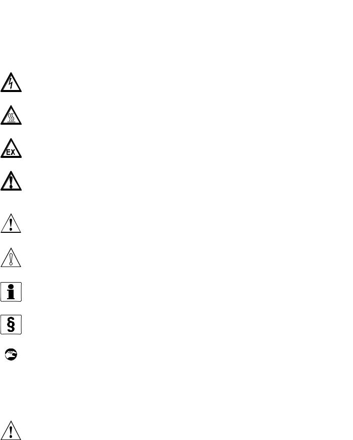
1.4.5 Warnings and symbols used
Safety warnings are indicated by the following symbols.
DANGER!
This information refers to the immediate danger when working with electricity.
DANGER!
This warning refers to the immediate danger of burns caused by heat or hot surfaces.
DANGER!
This warning refers to the immediate danger when using this device in a hazardous atmosphere.
DANGER!
These warnings must be observed without fail. Even partial disregard of this warning can lead to serious health problems and even death. There is also the risk of seriously damaging the device or parts of the operator's plant.
WARNING!
Disregarding this safety warning, even if only in part, poses the risk of serious health problems. There is also the risk of damaging the device or parts of the operator's plant.
CAUTION!
Disregarding these instructions can result in damage to the device or to parts of the operator's plant.
INFORMATION!
These instructions contain important information for the handling of the device.
LEGAL NOTICE!
This note contains information on statutory directives and standards.
• HANDLING
This symbol designates all instructions for actions to be carried out by the operator in the specified sequence.
iRESULT
This symbol refers to all important consequences of the previous actions.
1.5Safety instructions for the operator
WARNING!
In general, devices from the manufacturer may only be installed, commissioned, operated and maintained by properly trained and authorized personnel.
This document is provided to help you establish operating conditions, which will permit safe and efficient use of this device.
12 |
www.krohne.com |
02/2012 - 4000498602 - MA MFC 300 R03 en |
|
|
DEVICE DESCRIPTION 2 |
|
MFC 300 |
|
|
|
|
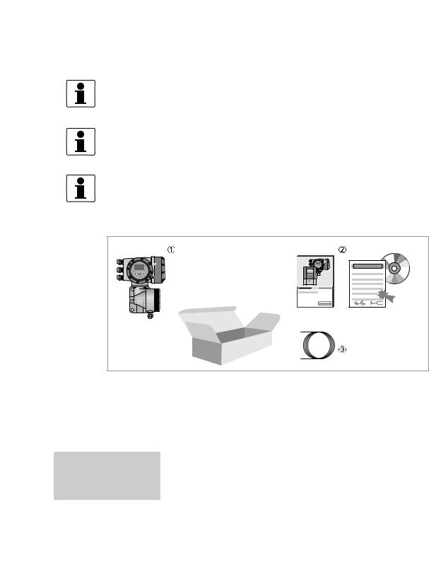
2.1 Scope of delivery
INFORMATION!
Inspect the cartons carefully for damages or signs of rough handling. Report damage to the carrier and to the local office of the manufacturer.
INFORMATION!
Do a check of the packing list to make sure that you have all the elements given in the order.
INFORMATION!
Look at the device nameplate to ensure that the device is delivered according to your order.
Check for the correct supply voltage printed on the nameplate.
Figure 2-1: Scope of delivery
1Device in the version as ordered
2Documentation (calibration report, factory and material certification if ordered, CD-Rom with product documentation for measuring sensor and signal converter)
3Signal cable (only for remote version)
Signal converter / measuring sensor combination possibilities
Measuring sensor |
Signal converter MFC 300 |
|
|
|
|
|
|
|
|
|
Compact |
Remote field |
Remote wall- |
Remote rack- |
|
|
housing |
mounted housing |
mounted housing |
|
|
|
|
|
OPTIMASS 1000 |
OPTIMASS 1300 C |
OPTIMASS 1300 F |
OPTIMASS 1300 W |
OPTIMASS 1300 R |
|
|
|
|
|
OPTIMASS 2000 |
OPTIMASS 2300 C |
OPTIMASS 2300 F |
OPTIMASS 2300 W |
OPTIMASS 2300 R |
|
|
|
|
|
OPTIMASS 3000 |
OPTIMASS 3300 C |
OPTIMASS 3300 F |
OPTIMASS 3300 W |
OPTIMASS 3300 R |
|
|
|
|
|
OPTIMASS 7000 |
OPTIMASS 7300 C |
OPTIMASS 7300 F |
OPTIMASS 7300 W |
OPTIMASS 7300 R |
|
|
|
|
|
OPTIMASS 8000 |
OPTIMASS 8300 C |
OPTIMASS 8300 F |
OPTIMASS 8300 W |
OPTIMASS 8300 R |
|
|
|
|
|
02/2012 - 4000498602 - MA MFC 300 R03 en |
www.krohne.com |
13 |
2 DEVICE DESCRIPTION |
|
|
MFC 300 |
|
|
|
|
|
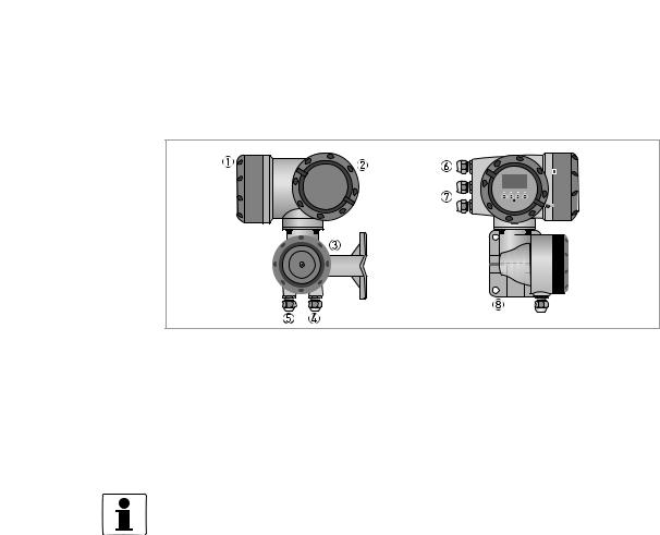
2.2 Device description
The mass flowmeters are designed exclusively to directly measure mass flow rates, product density and temperature as well to indirectly measure parameters such as the total volume and concentration of dissolved substances as well as the volume flow rate.
Your measuring device is supplied ready for operation. The factory settings for the operating data have been made in accordance with your order specifications.
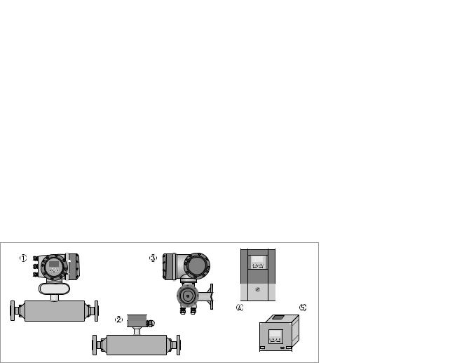
The following versions are available:
•Compact version (the signal converter is mounted directly on the measuring sensor)
•Remote version (electrical connection to the measuring sensor via field current and signal cable)
Figure 2-2: Device versions
1Compact version
2Measuring sensor with connection box
3Field housing
4Wall-mounted housing
519" rack-mounted housing
14 |
www.krohne.com |
02/2012 - 4000498602 - MA MFC 300 R03 en |
|
|
DEVICE DESCRIPTION 2 |
|
MFC 300 |
|
|
|
|
2.2.1 Field housing
Figure 2-3: Construction of the field housing
1Cover for electronics and display
2Cover for power supply and inputs/outputs terminal compartment
3Cover for measuring sensor terminal compartment with locking screw
4Cable entry for measuring sensor signal cable
5Cable entry for measuring sensor field current cable
6Cable entry for power supply
7Cable entry for inputs and outputs
8Mounting plate for pipe and wall mounting
INFORMATION!
Each time a housing cover is opened, the thread should be cleaned and greased. Use only resinfree and acid-free grease.
Ensure that the housing gasket is properly fitted, clean and undamaged.
02/2012 - 4000498602 - MA MFC 300 R03 en |
www.krohne.com |
15 |
2 DEVICE DESCRIPTION |
|
|
|
|
|
|
|
|
|
|
|||||||||||
|
|
|
|
|
|
|
|
MFC 300 |
|
||||||||||||
2.2.2 Wall-mounted housing |
|
|
|
|
|
|
|
|
|
|
|||||||||||
|
|
|
|
|
|
|
|
|
|
||||||||||||
|
|
|
|
|
|
|
|
|
|
|
|
|
|
|
|
|
|
|
|
|
|
|
|
|
|
|
|
|
|
|
|
|
|
|
|
|
|
|
|
|
|
|
|
|
|
|
|
|
|
|
|
|
|
|
|
|
|
|
|
|
|
|
|
|
|
|
|
|
|
|
|
|
|
|
|
|
|
|
|
|
|
|
|
|
|
|
|
|
|
|
|
|
|
|
|
|
|
|
|
|
|
|
|
|
|
|
|
|
|
|
|
|
|
|
|
|
|
|
|
|
|
|
|
|
|
|
|
|
|
|
|
|
|
|
|
|
|
|
|
|
|
|
|
|
|
|
|
|
|
|
|
|
|
|
|
|
|
|
|
|
|
|
|
|
|
|
|
|
|
|
|
|
|
|
|
|
|
|
|
|
|
|
|
|
|
|
|
|
|
|
|
|
|
|
|
|
|
|
|
|
|
|
|
|
|
|
|
|
|
|
|
|
|
|
|
|
|
|
|
|
|
|
|
|
|
|
|
|
|
|
|
|
|
|
|
|
|
|
|
|
|
|
|
|
|
|
|
|
|
|
|
|
|
|
|
|
|
|
|
|
|
|
|
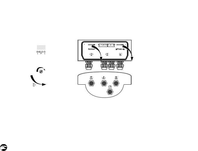
Figure 2-4: Construction of wall-mounted housing
1Cover for terminal compartments
2Terminal compartment for measuring sensor
3Terminal compartment for inputs and outputs
4Terminal compartment for power supply with safety cover (shock-hazard protection)
5Cable entry for measuring sensor cable
6Cable entry for inputs and outputs
7Cable entry for inputs and outputs
8Cable entry for power supply
1 Turn lock to the right and open the cover.
16 |
www.krohne.com |
02/2012 - 4000498602 - MA MFC 300 R03 en |

|
|
DEVICE DESCRIPTION 2 |
|
MFC 300 |
|
|
|
|
2.3 Nameplates
INFORMATION!
Look at the device nameplate to ensure that the device is delivered according to your order. Check for the correct supply voltage printed on the nameplate.
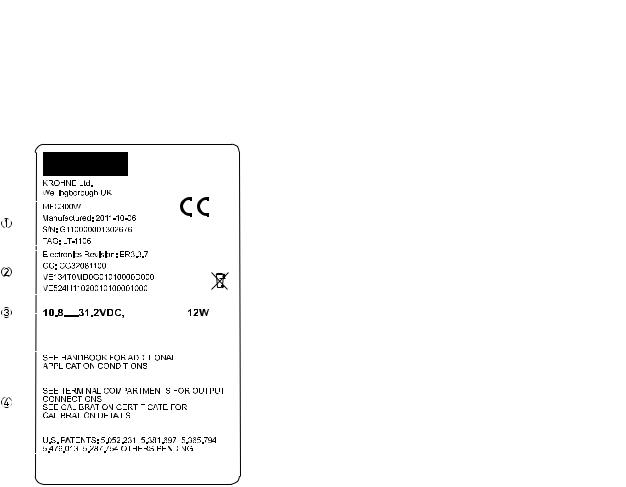
2.3.1 Compact version (example)
Figure 2-5: Example of nameplate for the compact version
1Approvals-related information: Ex approval, EC type test certificate, hygienic approvals, etc.
2Approvals-related thresholds
3Additional information on documentation, calibration and patents
4Protection category
5Approvals-related pressure and temperature thresholds
6Electrical connection data
7Software and hardware revision (Electronics Revision), CG number, order number for signal converter and measuring sensor
8Manufacturing date, serial number and TAG number
9Product description
02/2012 - 4000498602 - MA MFC 300 R03 en |
www.krohne.com |
17 |
2 DEVICE DESCRIPTION |
|
|
|
|
|
|
|
|
|
|
|
|||||||||||||||
|
|
|
|
|
|
|
|
|
MFC 300 |
|
||||||||||||||||
2.3.2 Remote version (example) |
|
|
|
|
|
|
|
|
|
|
|
|||||||||||||||
|
|
|
|
|
|
|
|
|
|
|
||||||||||||||||
|
|
|
|
|
|
|
|
|
|
|
|
|
|
|
|
|
|
|
|
|
|
|
|
|
|
|
|
|
|
|
|
|
|
|
|
|
|
|
|
|
|
|
|
|
|
|
|
|
|
|
|
|
|
|
|
|
|
|
|
|
|
|
|
|
|
|
|
|
|
|
|
|
|
|
|
|
|
|
|
|
|
|
|
|
|
|
|
|
|
|
|
|
|
|
|
|
|
|
|
|
|
|
|
|
|
|
|
|
|
|
|
|
|
|
|
|
|
|
|
|
|
|
|
|
|
|
|
|
|
|
|
|
|
|
|
|
|
|
|
|
|
|
|
|
|
|
|
|
|
|
|
|
|
|
|
|
|
|
|
|
|
|
|
|
|
|
|
|
|
|
|
|
|
|
|
|
|
|
|
|
|
|
|
|
|
|
|
|
|
|
|
|
|
|
|
|
|
|
|
|
|
|
|
|
|
|
|
|
|
|
|
|
|
|
|
|
|
|
|
|
|
|
|
|
|
|
|
|
|
|
|
|
|
|
|
|
|
|
|
|
|
|
|
|
|
|
|
|
|
|
|
|
|
|
|
|
|
|
|
|
|
|
|
|
|
|
|
|
|
|
|
|
|
|
|
|
|
|
|
|
|
|
|
|
|
|
|
|
|
|
|
|
|
|
|
|
|
|
|
|
|
|
|
|
|
|
|
|
|
|
|
|
|
|
|
|
|
|
|
|
|
|
|
|
|
|
|
|
|
|
|
|
|
|
|
|
|
|
|
|
|
|
|
|
|
|
|
|
|
|
|
|
|
|
|
|
|
|
|
|
|
|
|
|
|
|
|
|
|
|
|
|
|
|
|
|
|
|
|
|
|
|
|
|
|
|
|
|
|
|
|
|
|
|
|
|
|
|
|
|
|
|
|
|
|
|
|
|
|
|
|
|
|
|
|
|
|
|
|
|
|
|
|
|
|
|
|
|
|
|
|
|
|
|
|
|
|
|
|
|
|
|
|
|
|
|
|
|
|
|
|
|
|
|
|
|
|
|
|
|
|
|
|
|
|
|
|
|
|
|
|
|
|
|
|
|
|
|
|
|
|
|
|
|
|
|
|
|
|
|
|
|
|
|
|
|
|
|
|
|
|
|
|
|
|
|
|
|
|
|
|
|
|
|
|
|
|
|
|
|
|
|
|
|
|
|
|
|
|
|
|
|
|
|
|
|
|
|
|
|
|
|
|
|
|
|
|
|
|
|
|
|
|
|
|
|
|
|
|
|
|
|
|
|
|
|
|
|
|
|
|
|
|
|
|
|
|
|
|
|
|
|
|
|
|
|
|
|
|
|
|
|
|
|
|
|
|
|
|
|
|
|
|
|
|
|
|
|
|
|
|
|
|
|
|
|
|
|
|
|
|
|
|
|
|
|
|
|
|
|
|
|
|
|
|
|
|
|
|
|
|
|
|
|
|
|
|
|
|
|
|
|
|
|
|
|
|
|
|
|
|
|
|
|
|
|
|
|
|
|
|
|
|
|
|
|
|
|
|
|
|
|
|
|
|
|
|
|
|
|
|
|
|
|
|
|
|
|
|
|
|
|
|
|
|
|
|
|
|
|
|
|
|
|
|
|
|
|
|
|
|
|
|
|
|
|
|
|
|
|
|
|
|
|
|
|
|
|
|
|
|
|
|
|
|
|
|
|
|
|
|
|
|
|
|
Figure 2-6: Example of a nameplate for the remote version
1Product designation, manufacturing date, serial number and TAG number
2Software and hardware revision (Electronics Revision), CG number, order number for signal converter and measuring sensor
3Electrical connection data
4Additional information on documentation, calibration and patents
18 |
www.krohne.com |
02/2012 - 4000498602 - MA MFC 300 R03 en |
|
|
DEVICE DESCRIPTION 2 |
|
MFC 300 |
|
|
|
|
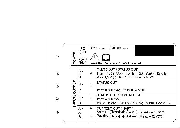
2.3.3 Electrical connection data of inputs/outputs (example of basic version)
Figure 2-7: Example of a nameplate for electrical connection data of inputs and outputs
1Power supply (AC: L and N; DC: L+ and L-; PE for ≥ 24 VAC; FE for ≤ 24 VAC and DC)
2Connection data of connection terminal D/D-
3Connection data of connection terminal C/C-
4Connection data of connection terminal B/B-
5Connection data of connection terminal A/A-; A+ only operable in the basic version
•A = active mode; the signal converter supplies the power for connection of the subsequent devices
•P = passive mode; external power supply required for operation of the subsequent devices
•N/C = connection terminals not connected
02/2012 - 4000498602 - MA MFC 300 R03 en |
www.krohne.com |
19 |
3 INSTALLATION |
|
|
MFC 300 |
|
|
|
|
|
3.1 Notes on installation
INFORMATION!
Inspect the cartons carefully for damages or signs of rough handling. Report damage to the carrier and to the local office of the manufacturer.
INFORMATION!
Do a check of the packing list to make sure that you have all the elements given in the order.
INFORMATION!
Look at the device nameplate to ensure that the device is delivered according to your order. Check for the correct supply voltage printed on the nameplate.
3.2Storage
•Store the device in a dry, dust-free location.
•Avoid continuous direct sunlight.
•Store the device in its original packing.
•Storage temperature: -50...+70°C / -58...+158°F
3.3Transport
Signal converter
• No special requirements.
Compact version
•Do not lift the device by the signal converter housing.
•Do not use lifting chains.
•To transport flange devices, use lifting straps. Wrap these around both process connections.
3.4Installation specifications
INFORMATION!
The following precautions must be taken to ensure reliable installation.
•Make sure that there is adequate space to the sides.
•Protect the signal converter from direct sunlight and install a sun shade if necessary.
•Signal converters installed in control cabinets require adequate cooling, e.g. by fan or heat exchanger.
•Do not expose the signal converter to intense vibration. The flowmeters are tested for a vibration level in accordance with IEC 68-2-3.
20 |
www.krohne.com |
02/2012 - 4000498602 - MA MFC 300 R03 en |
|
|
INSTALLATION 3 |
|
MFC 300 |
|
|
|
|
3.5 Mounting of the compact version
INFORMATION!
The signal converter is mounted directly on the measuring sensor. For installation of the flowmeter, please observe the instructions in the supplied product documentation for the measuring sensor.
3.6 Mounting the field housing, remote version
INFORMATION!
Assembly materials and tools are not part of the delivery. Use the assembly materials and tools in compliance with the applicable occupational health and safety directives.
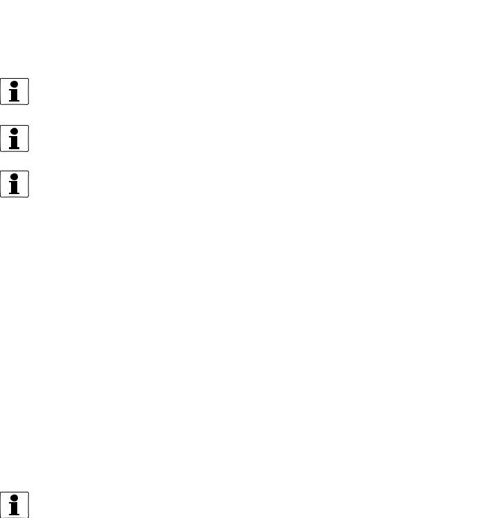
3.6.1 Pipe mounting
Figure 3-1: Pipe mounting of the field housing
1 Fix the signal converter to the pipe.
2Fasten the signal converter using standard U-bolts and washers.
3Tighten the nuts.
02/2012 - 4000498602 - MA MFC 300 R03 en |
www.krohne.com |
21 |
3 INSTALLATION |
|
|
|
|
|
|
|
|
|
|
|
|
|
|
|
|
|
|
|
|
|
|
|
|
|
|
|
MFC 300 |
|
||
3.6.2 Wall mounting |
|
|
|
|
|
|
|
|
|
|
|
|
|
|
|
|
|
|
|
|
|
|
|
|
|
|
|
|
|
||
|
|
|
|
|
|
|
|
|
|
|
|
|
|
|
|
|
|
|
|
|
|
|
|
|
|
|
|
|
|
|
|
|
|
|
|
|
|
|
|
|
|
|
|
|
|
|
|
|
|
|
|
|
|
|
|
|
|
|
|
|
|
|
|
|
|
|
|
|
|
|
|
|
|
|
|
|
|
|
|
|
|
|
|
|
|
|
|
|
|
|
|
|
|
|
|
|
|
|
|
|
|
|
|
|
|
|
|
|
|
|
|
|
|
|
|
|
|
|
|
|
|
|
|
|
|
|
|
|
|
|
|
|
|
|
|
|
|
|
|
|
|
|
|
|
|
|
|
|
|
|
|
|
|
|
|
|
|
|
|
|
|
|
|
|
|
|
|
|
|
|
|
|
|
|
|
|
|
|
|
|
|
|
|
|
|
|
|
|
|
|
|
|
|
|
|
|
|
|
|
|
|
|
|
|
|
|
|
|
|
|
|
|
|
|
|
|
|
|
|
|
|
|
|
|
|
|
|
|
|
|
|
|
|
|
|
|
|
|
|
|
|
|
|
|
|
|
|
|
|
|
|
|
|
|
|
Figure 3-2: Wall mounting of the field housing
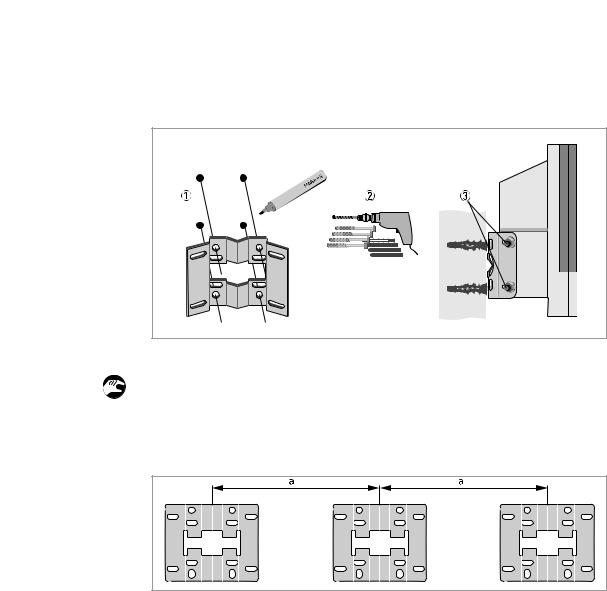
1 Prepare the holes with the aid of the mounting plate. For further information refer to Mounting plate, field housing on page 146.
2Use the mounting material and tools in compliance with the applicable occupational health and safety directives.
3Fasten the housing securely to the wall.
Mounting multiple devices next to each other
a ≥ 600 mm / 23.6" |
b ≥ 250 mm / 9.8" |
22 |
www.krohne.com |
02/2012 - 4000498602 - MA MFC 300 R03 en |
|
|
INSTALLATION 3 |
|
MFC 300 |
|
|
|
|
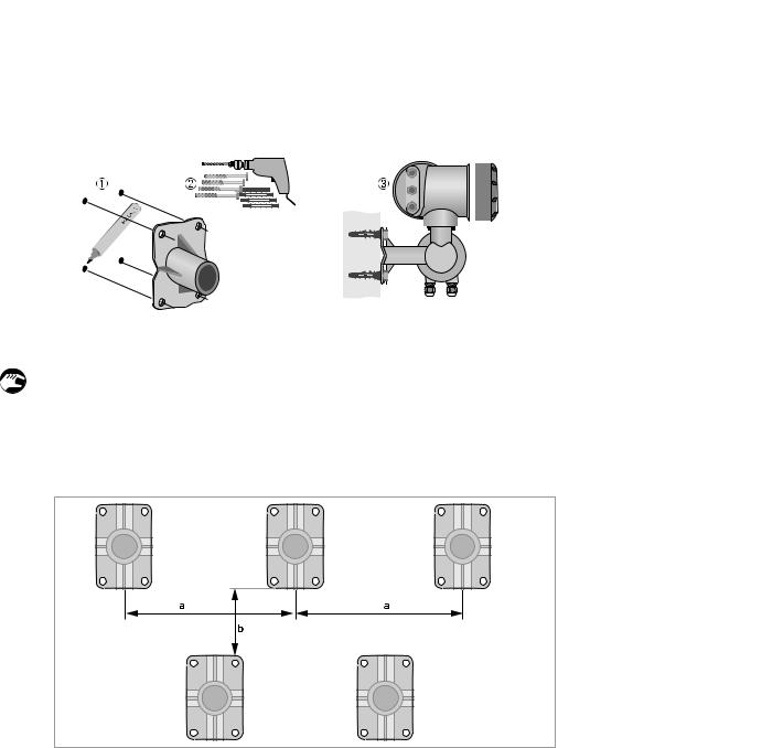
3.6.3 Turning the display of the field housing version
Figure 3-3: Turning the display of the field housing version
The display of the field housing version can be turned in 90° increments.
1Unscrew the cover from the display and operation control unit.
2Using a suitable tool, pull out the two metal puller devices to the left and right of the display.
3Pull out the display between the two metal puller devices and rotate it to the required position.
4Slide the display and then the metal puller devices back into the housing.
5Re-fit the cover and tighten it by hand.
CAUTION!
The ribbon cable of the display must not be folded or twisted repeatedly.
INFORMATION!
Each time a housing cover is opened, the thread should be cleaned and greased. Use only resinfree and acid-free grease.
Ensure that the housing gasket is properly fitted, clean and undamaged.
02/2012 - 4000498602 - MA MFC 300 R03 en |
www.krohne.com |
23 |
3 INSTALLATION |
|
|
MFC 300 |
|
|
|
|
|
3.7 Mounting the wall-mounted housing, remote version
INFORMATION!
Assembly materials and tools are not part of the delivery. Use the assembly materials and tools in compliance with the applicable occupational health and safety directives.
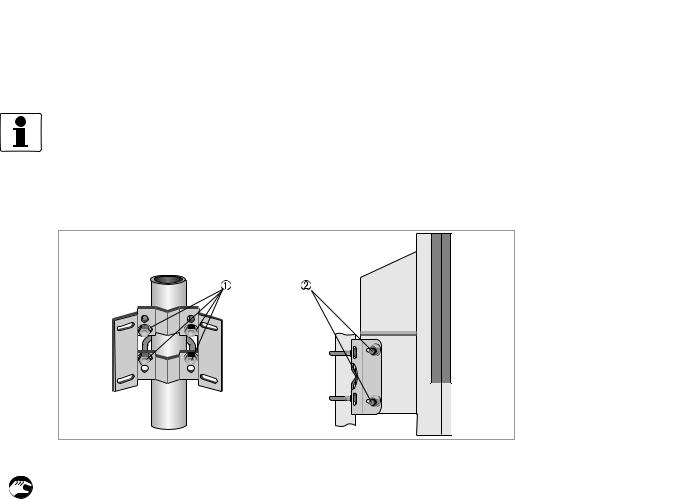
3.7.1 Pipe mounting
Figure 3-4: Pipe mounting of the wall-mounted housing
1 Fasten the mounting plate to the pipe with standard U-bolts, washers and fastening nuts. 2 Screw the signal converter to the mounting plate with the nuts and washers.
24 |
www.krohne.com |
02/2012 - 4000498602 - MA MFC 300 R03 en |
|
|
INSTALLATION 3 |
|
MFC 300 |
|
|
|
|
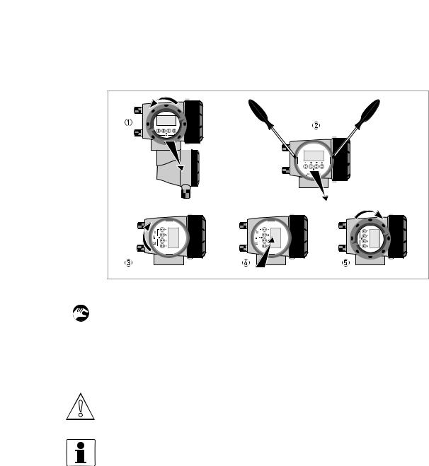
3.7.2 Wall mounting
Figure 3-5: Wall mounting of the wall-mounted housing
1 Prepare the holes with the aid of the mounting plate. For further information refer to Mounting plate, wall-mounted housing on page 146.
2Fasten the mounting plate securely to the wall.
3Screw the signal converter to the mounting plate with the nuts and washers.
Mounting multiple devices next to each other
a ≥ 240 mm / 9.4" |
02/2012 - 4000498602 - MA MFC 300 R03 en |
www.krohne.com |
25 |

4 ELECTRICAL CONNECTIONS |
|
|
MFC 300 |
|
|
|
|
|
4.1 Safety instructions
DANGER!
All work on the electrical connections may only be carried out with the power disconnected. Take note of the voltage data on the nameplate!
DANGER!
Observe the national regulations for electrical installations!
DANGER!
For devices used in hazardous areas, additional safety notes apply; please refer to the Ex documentation.
WARNING!
Observe without fail the local occupational health and safety regulations. Any work done on the electrical components of the measuring device may only be carried out by properly trained specialists.
INFORMATION!
Look at the device nameplate to ensure that the device is delivered according to your order. Check for the correct supply voltage printed on the nameplate.
4.2 Important notes on electrical connection
DANGER!
Electrical connection is carried out in conformity with the VDE 0100 directive "Regulations for electrical power installations with line voltages up to 1000 V" or equivalent national regulations.
CAUTION!
•Use suitable cable entries for the various electrical cables.
•The measuring sensor and signal converter have been configured together at the factory. For this reason, please connect the devices in pairs.
26 |
www.krohne.com |
02/2012 - 4000498602 - MA MFC 300 R03 en |

|
|
ELECTRICAL CONNECTIONS 4 |
|
MFC 300 |
|
|
|
|
4.3 Requirements for signal cables provided by the customer
INFORMATION!
If the signal cable was not ordered, it is to be provided by the customer. The following requirements regarding the electrical values of the signal cable must be observed:
Specifications for standard signal cables
•2 twisted double wire circuits
•20 AWG twisted, tinned copper conductors (19 mm / 0.2")
•Completely tinned copper shielding
•Casing colour: grey
•Colour of wires: Pair 1: black / red Pair 2 : green / white
•Test voltage: ≥ 500 VAC RMS (750 VDC)
•Temperature range: -20...+105°C / -4...+221°F
•Capacity: ≤ 200 pF/m / 61 pF/ft
•Inductance: ≤ 0.7 µH/m / 0.2 µH/ft
Specifications for cables in hazardous areas
•2 shielded twisted double wire circuits
•20 AWG twisted, tinned copper conductors (19 mm / 0.2")
•Casing colour: blue
•Colour of wires: Pair 1: black / red Pair 2 : green / white
•Test voltage: ≥ 500 VAC RMS (750 VDC)
•Temperature range: -20...+105°C / -4...+221°F
•Capacity: ≤ 200 pF/m / 61 pF/ft
•Inductance: ≤ 0.7 µH/m / 0.2 µH/ft
02/2012 - 4000498602 - MA MFC 300 R03 en |
www.krohne.com |
27 |

4 ELECTRICAL CONNECTIONS |
|
|
MFC 300 |
|
|
|
|
|
4.4 Connecting the signal cables
DANGER!
Cables may only be connected when the power is switched off.
DANGER!
The device must be grounded in accordance with regulations in order to protect personnel against electric shocks.
DANGER!
For devices used in hazardous areas, additional safety notes apply; please refer to the Ex documentation.
WARNING!
Observe without fail the local occupational health and safety regulations. Any work done on the electrical components of the measuring device may only be carried out by properly trained specialists.
28 |
www.krohne.com |
02/2012 - 4000498602 - MA MFC 300 R03 en |
|
|
ELECTRICAL CONNECTIONS 4 |
|
MFC 300 |
|
|
|
|
4.4.1 Connection of signal cable, field housing
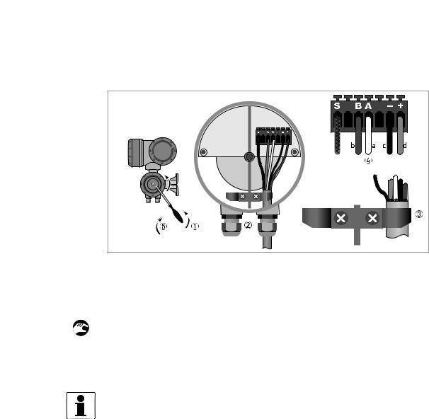
Figure 4-1: Electrical connection of the signal cables, field housing
a = white b = green c = black d = red
1 Remove the locking screw and open the housing cover.
2Pass the prepared signal cable through the cable entry.
3Secure the signal cable using the clip.
4Connect the electrical conductors as shown. The shielding is connected to terminal S.
5Close the housing cover and secure it with the locking screw.
INFORMATION!
Each time a housing cover is opened, the thread should be cleaned and greased. Use only resinfree and acid-free grease.
Ensure that the housing gasket is properly fitted, clean and undamaged.
02/2012 - 4000498602 - MA MFC 300 R03 en |
www.krohne.com |
29 |
4 ELECTRICAL CONNECTIONS |
|
|
|
|
|
|
|
|
|
|
|
|||||||||||||
|
|
|
|
|
|
|
|
|
MFC 300 |
|
||||||||||||||
4.4.2 Connection of signal cable, wall-mounted housing |
|
|
||||||||||||||||||||||
|
|
|||||||||||||||||||||||
|
|
|
|
|
|
|
|
|
|
|
|
|
|
|
|
|
|
|
|
|
|
|
|
|
|
|
|
|
|
|
|
|
|
|
|
|
|
|
|
|
|
|
|
|
|
|
|
|
|
|
|
|
|
|
|
|
|
|
|
|
|
|
|
|
|
|
|
|
|
|
|
|
|
|
|
|
|
|
|
|
|
|
|
|
|
|
|
|
|
|
|
|
|
|
|
|
|
|
|
|
|
|
|
|
|
|
|
|
|
|
|
|
|
|
|
|
|
|
|
|
|
|
|
|
|
|
|
|
|
|
|
|
|
|
|
|
|
|
|
|
|
|
|
|
|
|
|
|
|
|
|
|
|
|
|
|
|
|
|
|
|
|
|
|
|
|
|
|
|
|
|
|
|
|
|
|
|
|
|
|
|
|
|
|
|
|
|
|
|
|
|
|
|
|
|
|
|
|
|
|
|
|
|
|
|
|
|
|
|
|
|
|
|
|
|
|
|
|
|
|
|
|
|
|
|
|
|
|
|
|
|
|
|
|
|
|
|
|
|
|
|
|
|
|
|
|
|
|
|
|
|
|
|
|
|
|
|
|
|
|
|
|
|
|
|
|
|
|
|
|
|
|
|
|
|
|
|
|
|
|
|
|
|
|
|
|
|
|
|
|
|
|
|
|
|
|
|
|
|
|
|
|
|
|
|
|
|
|
|
|
|
|
|
|
|
|
|
|
|
|
|
|
|
|
|
|
|
|
|
|
|
|
|
|
|
|
|
|
|
|
|
|
|
|
|
|
|
|
|
|
|
|
|
|
|
|
|
|
|
|
|
|
|
|
|
|
|
|
|
|
|
|
|
|
|
|
|
|
|
|
|
|
|
|
|
|
|
|
|
|
|
|
|
|
|
|
|
|
|
|
|
|
|
|
|
|
|
|
|
|
|
|
|
|
|
|
|
|
|
|
|
|
|
|
|
|
|
|
|
|
|
|
|
|
|
|
|
|
|
|
|
|
|
|
|
|
|
|
|
|
|
|
|
|
|
|
|
|
|
|
|
|
|
|
|
|
|
|
|
|
|
|
|
|
|
|
|
|
|
|
|
|
|
|
|
|
|
|
|
|
|
|
|
|
|
|
|
|
|
|
|
|
|
|
|
|
|
|
|
|
|
|
|
|
|
|
|
|
|
|
|
|
|
|
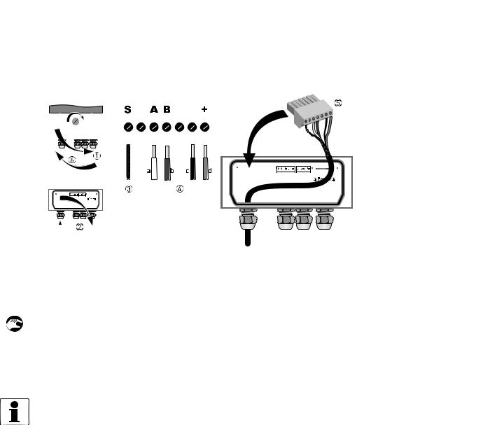
Figure 4-2: Electrical connection of signal cable, wall-mounted housing
a = white b = green c = black d = red
1 Open the housing cover.
2Open the cover and guide the prepared signal cable through the cable entry.
3Connect the twisted shielding to terminal S.
4Connect the electrical conductors to terminals +, -, A, B.
5Press the plug into the connector.
6Close the cover and the housing cover.
INFORMATION!
Each time a housing cover is opened, the thread should be cleaned and greased. Use only resinfree and acid-free grease.
Ensure that the housing gasket is properly fitted, clean and undamaged.
30 |
www.krohne.com |
02/2012 - 4000498602 - MA MFC 300 R03 en |
 Loading...