


 IFC 100 Supplementary instructions
Signal converter for electromagnetic flowmeters
Description of Foundation Fieldbus interface
Electronic Revision: ER 3.0.xx
The documentation is only complete when used in combination with the relevant documentation for the measuring sensor.
© KROHNE 02/2012 - 4001702901 - AD IFC 100 FF R01 en

|
CONTENTS |
IFC 100 |
|
|
|
||
|
|
|
|
1 Safety instructions |
3 |
|
1.1 |
Scope of the document..................................................................................................... |
3 |
1.2 |
Device description ............................................................................................................ |
3 |
2 Technical data |
4 |
|
2.1 |
Foundation Fieldbus data................................................................................................. |
4 |
3 Electrical connections |
5 |
|
3.1 |
Installation in hazardous area and bus cable.................................................................. |
5 |
3.2 |
Grounding of measuring sensor ...................................................................................... |
5 |
3.3 |
Foundation Fieldbus electrical connection...................................................................... |
5 |
3.4 |
Cable types ....................................................................................................................... |
6 |
3.5 |
Shielding and grounding .................................................................................................. |
6 |
3.6 |
Electrical connection of FOUNDATION Fieldbus ............................................................. |
7 |
3.7 |
Topology of FF networks .................................................................................................. |
8 |
4 Operation |
9 |
|
4.1 |
Settable functions............................................................................................................. |
9 |
4.2 |
Description of the FF block system................................................................................ |
10 |
4.3 |
Used abbreviations ......................................................................................................... |
10 |
4.4 |
Resource Block (RB) ...................................................................................................... |
11 |
4.4.1 Foundation Fieldbus parameters for Resource Block......................................................... |
11 |
|
4.4.2 Manufacturer specific parameters of the signal converter for Resource Block................. |
18 |
|
4.5 |
Transducer Block (TB).................................................................................................... |
23 |
4.5.1 Foundation Fieldbus parameters for Transducer Block ..................................................... |
23 |
|
4.5.2 Manufacturer specific parameters of the signal converter for Transducer Block ............. |
26 |
|
4.6 |
Analog Input Block (AI)................................................................................................... |
32 |
4.7 |
Integrator Block (IT) ....................................................................................................... |
40 |
4.8 |
Proportional Integral Derivative Block (PID) ................................................................. |
47 |
5 Notes |
|
61 |
2 |
www.krohne.com |
02/2012 - 4001702901 - AD IFC 100 FF R01 en |

|
|
SAFETY INSTRUCTIONS 1 |
|
IFC 100 |
|
|
|
|
1.1 Scope of the document
These instructions are supplementary to the standard product documentation of the signal converter. The details depicted therein, in particular the safety information are valid and should be adhered to. The present supplementary instructions provide additional information for the devices when being operated and connected to a Foundation Fieldbus.
INFORMATION!
The present supplementary instruction for the signal converter with Foundation Fieldbus interface, plus the software with the DD and CCF files are included in our scope of supply, in addition to those items delivered for the standard device.
1.2 Device description
Electromagnetic flowmeters are designed exclusively to measure the flow and conductivity of electrically conductive, liquid media.
Your measuring device is supplied ready for operation. The factory settings for the operating data have been made in accordance with your order specifications.
The following versions are available:
•Compact version (the signal converter is mounted directly on the measuring sensor)
•Remote version (electrical connection to the measuring sensor via field current and signal cable)
02/2012 - 4001702901 - AD IFC 100 FF R01 en |
www.krohne.com |
3 |

2 TECHNICAL DATA |
|
|
|
|
|
|
IFC 100 |
|
|||
|
|
|
|
||
2.1 Foundation Fieldbus data |
|||||
Description |
|
|
|
|
|
|
|
|
|
||
Type |
|
Electromagnetic flowmeter |
|
||
|
|
|
|
||
Physical layer |
|
Foundation Fieldbus protocol that agrees with IEC 61158-2 and FISCO model; |
|
|
|
|
|
galvanically isolated |
|
||
|
|
|
|
||
Communication standard |
|
H1 |
|
|
|
|
|
|
|
|
|
ITK version |
|
5.2 |
|
|
|
Data blocks |
|
|
|
|
|
|
|
|
|
||
Function blocks |
|
1 x Enhanced Resource Block (RB) |
|
||
|
|
|
|
||
|
|
1 x Customer Transducer Block (TB) |
|
|
|
|
|
|
|
||
|
|
3 x Analog Input Block (AI) |
|
|
|
|
|
|
|
||
|
|
2 x Integrator Block (IT) |
|
|
|
|
|
|
|
||
|
|
1 x Proportional Integral Derivate Block (PID) |
|
|
|
|
|
|
|
||
Execution time |
|
Analog Input Block: 10 ms |
|
|
|
|
|
|
|
||
|
|
Integrator Block: 15 ms |
|
|
|
|
|
|
|
||
|
|
Proportional Integral Derivate Block: 25 ms |
|
|
|
Electrical connections |
|
|
|
|
|
|
|
|
|
||
Device power supply |
|
Not intrinsically safe: 9...32 VDC |
|
||
|
|
|
|
||
|
|
Intrinsically safe: 9...24 VDC |
|
|
|
|
|
|
|
||
Basic current |
|
10.5 mA |
|
|
|
|
|
|
|
||
Maximum error current |
|
16.5 mA (= basic current + error current = 10.5 mA + 6 mA) |
|
|
|
|
|
|
|
||
Start current after 10 ms |
|
14 mA |
|
|
|
|
|
|
|
||
Polarity sensitivity |
|
No |
|
|
|
|
|
|
|
||
Minimum cycle time |
|
250 ms |
|
|
|
|
|
|
|
|
|
4 |
www.krohne.com |
02/2012 - 4001702901 - AD IFC 100 FF R01 en |

|
|
ELECTRICAL CONNECTIONS 3 |
|
IFC 100 |
|
|
|
|
3.1 Installation in hazardous area and bus cable
We recommend that a Foundation Fieldbus network in the hazardous area should be projected in accordance with PTB's FISCO model. The FISCO model is based on the following conditions:
•All electrical components which should be connected to the bus must be approved according to the FISCO model (even the termination).
•The maximum cable length should not exceed 1000 m / 3280.8 ft.
•The approved input values of the field devices (U0, I0, P0) comply to the output values of the power supply (e.g. segment coupler) according to: U0 ≤ Ui; I0 ≤ Ii; P0 ≤ Pi.
•The values of the cable must be within the following ranges: R' = 15…150 Ω/km; L' = 0.4…1 mH/km; C' = 45…200 nF/km
equivalent to
R' = 24…240 Ω/mile; L' = 0.65…1.6 mH/mile; C' = 72…320 nF/mile
Other limitations for the cable than the FISCO limitations are not existent. Nevertheless, a twisted pair and shielded cable is strongly recommended.
Example: a good quality cable could have the following data: 44 Ω/km = 70.4 Ω/mile; <90 nF/km
=<144 nF/mile; attenuation at 39 kHz: <3 dB/km = <4.9 dB/mile; impedance 100 Ω at 31.25 kHz.
3.2Grounding of measuring sensor
•The measuring sensor must be properly connected to ground.
•The grounding cable should not transmit any interference voltages.
•Do not use the grounding cable to connect more than one device to ground.
•In hazardous areas, grounding is used at the same time for equipotential bonding.
•The sensors are connected to ground by means of a functional grounding conductor FE.
DANGER!
Special grounding instructions are contained in the "Ex supplement", which are only supplied together with hazardous-duty equipment.
INFORMATION!
Special grounding instructions for the various measuring sensors are contained in the separate installation instructions for the measuring sensors. These instructions also contain detailed descriptions on how to use grounding rings and how to install the measuring sensors in metal or plastic pipes or in pipes which are coated on the inside.
3.3 Foundation Fieldbus electrical connection
The output and input groups are electrically isolated from each other and from all other input and output circuits.
DANGER!
The signal converter must be properly grounded to avoid personnel shock hazard. All directions, operating data and connection diagrams do not apply to devices used in hazardous areas; in such cases, read the special Ex instructions without fail!
02/2012 - 4001702901 - AD IFC 100 FF R01 en |
www.krohne.com |
5 |

3 ELECTRICAL CONNECTIONS
3.4 Cable types
IFC 100 
The cable types are specified according to IEC 61158-2. Shielded cables offer the advantage of malfunction-free operation with adequate protection against electromagnetic influences, and make it possible to employ the full performance of the Foundation Fieldbus system.
Core cross-section |
0.8 mm2 or |
0.32 mm2 or |
0.13 mm2 or |
1.25 mm2 or |
|
AWG 18 |
AWG 22 |
AWG 26 |
AWG 16 |
|
|
|
|
|
Cable type |
A |
B |
C |
D |
|
|
|
|
|
|
twisted pair, |
individual or |
multiple twisted |
multiple non- |
|
individually |
multiple twisted |
pairs, without |
twisted cables, |
|
shielded |
pairs with overall |
shielding |
without shielding |
|
|
shield |
|
|
Max. length |
1900 m / 6200 ft |
1200 m / 3900 ft |
400 m / 1300 ft |
200 m / 650 ft |
incl. branch line |
|
|
|
|
In non-hazardous areas the maximum number of field devices is limited to 32. For detailed information refer to the following table.
In non-hazardous areas the ignition protection class of the devices and the limited electric power available limit the number of field devices to 4.
Number of devices |
Cable lengths for number of devices per branch line |
|||
|
|
|
|
|
|
1 device |
2 devices |
3 devices |
4 devices |
|
|
|
|
|
25...32 |
1 m / 3.3 ft |
1 m / 3.3 ft |
1 m / 3.3 ft |
1 m / 3.3 ft |
|
|
|
|
|
19...24 |
30 m / 100 ft |
1 m / 3.3 ft |
1 m / 3.3 ft |
1 m / 3.3 ft |
|
|
|
|
|
15...18 |
60 m / 200 ft |
30 m / 100 ft |
1 m / 3.3 ft |
1 m / 3.3 ft |
|
|
|
|
|
13...14 |
90 m / 300 ft |
60 m / 200 ft |
30 m / 100 ft |
1 m / 3.3 ft |
|
|
|
|
|
1..12 |
120 m / 400 ft |
90 m / 300 ft |
60 m / 200 ft |
30 m / 100 ft |
|
|
|
|
|
All bus segments must be fitted with a terminator at both ends.
3.5Shielding and grounding
•For optimum electromagnetic compatibility of systems it is extremely important that the system components, and particularly the bus cables connecting the components, are shielded and that such shields - if possible - form an unbroken cover.
•Hence, it follows that, for use in non-hazardous duty systems, the cable shield should be grounded as often as possible.
•In Ex systems an adequate equipotential bonding in the hazardous and non-hazardous location along the entire Fieldbus installation is strongly recommended. Multiple grounding of the shield is of advantage.
INFORMATION!
The use of twisted and shielded cables is strongly recommended, otherwise EMC protection of the signal converter cannot be assured.
6 |
www.krohne.com |
02/2012 - 4001702901 - AD IFC 100 FF R01 en |

|
|
ELECTRICAL CONNECTIONS 3 |
|
IFC 100 |
|
|
|
|
3.6 Electrical connection of FOUNDATION Fieldbus
INFORMATION!
The wiring between the device and the FOUNDATION Fieldbus cable is independant of polarity. The signal converter FOUNDATION Fieldbus interface will operate only if the additional power supply for the device is connected/available.
For a detailed description of the electrical connections please refer to the standard signal converter handbook.
Connection to a spur
or
Connection to a trunk
or
1 e.g. incoming data lines
2 e.g. outgoing data lines
02/2012 - 4001702901 - AD IFC 100 FF R01 en |
www.krohne.com |
7 |
3 ELECTRICAL CONNECTIONS
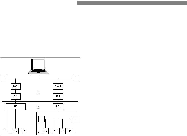
3.7 Topology of FF networks
IFC 100 
An example of mixed topology of FF networks is shown in the following example.
Connection is best made via short branch cables and T connectors. This connection type makes it possible to connect and disconnect the devices without interrupting the bus or the communication.
1 |
2 |
3 |
B1+B2 |
D1-D3 |
D4-D6 |
I.S. |
JB |
PS |
T |
HSE network H1 bus
Intrisically safe, explosive area
Bridge = coupling element for H1 bus and HSE network
Device = field devices, own power supply, for non potentially explosive areas
Intrinsically safe devices, external power supply, for potentially explosive areas
Intrinsically safe barrier Junction box for field devices Power supply
Switch = connection of multiple HSE sub networks
Terminator
8 |
www.krohne.com |
02/2012 - 4001702901 - AD IFC 100 FF R01 en |

|
|
OPERATION 4 |
|
IFC 100 |
|
|
|
|
4.1Settable functions
•For Foundation Fieldbus the totalizers of the signal converter are not available!
•The following tables describe only the menus, functions and parameters that are different between the standard signal converter and the Foundation Fieldbus signal converter.
•For the electrical connections of the outputs, inputs and all settings of functions that are not listed in the following tables refer to the standard product documentation.
No. |
Displayed text |
Description and settings |
|
|
|
A quick setup
A2 |
Tag |
Identifier for the measurement in a plant, appears in the display header |
|
|
(maximum 8 digits). |
|
|
|
|
|
Note: Only read, not changeable! |
|
|
|
B test
B3.5 |
Foundation fieldbus |
Display information about Foundation fieldbus interface. |
|
|
|
C setup
C1.2.3 |
time constant |
For all flow measurements and outputs. |
|
|
|
|
|
xxx.x s; range: 0.0…100 s |
|
|
Note: Only read, not changeable! |
|
|
|
C5.1.1 |
Tag |
Identifier for the measurement in a plant, appears in the display header |
|
|
(maximum 8 digits). |
|
|
Note: Only read, not changeable! |
|
|
|
C3 |
Totalizer |
Not available for Foundation Fieldbus devices! |
|
|
|
C4 |
I/O HART |
Not available for Foundation Fieldbus devices! |
|
|
|
C5.4 |
2. meas. page |
In case of Foundation Fieldbus device, the second measurement page is |
|
|
meant to check the output values of the different function blocks. Only |
|
|
Foundation Fieldbus values can be selected here. The analogue inputs are |
|
|
shown with exactly the value, seen on the bus system. |
|
|
|
C5.4.1 |
measurement 1.line |
Select: AI1 analog inp. / AI2 analog inp. / AI3 analog inp. / PID / INT1 |
|
|
integrator / INT2 integrator / |
|
|
|
C5.4.2 |
format 1.line |
Fixed number of digits after the decimal point or automatic, where the |
|
|
number of digits is automatically adjusted to the available space. |
|
|
|
C5.4.3 |
measurement 2.line |
Select: AI1 analog inp. / AI2 analog inp. / AI3 analog inp. / PID / INT1 |
|
|
integrator / INT2 integrator / |
|
|
|
C5.4.4 |
format 2.line |
Fixed number of digits after the decimal point or automatic, where the |
|
|
number of digits is automatically adjusted to the available space. |
|
|
|
C5.4.5 |
measurement 3.line |
Select: AI1 analog inp. / AI2 analog inp. / AI3 analog inp. / PID / INT1 |
|
|
integrator / INT2 integrator / |
|
|
|
C5.4.6 |
format 3.line |
Fixed number of digits after the decimal point or automatic, where the |
|
|
number of digits is automatically adjusted to the available space. |
|
|
|
C5.8 |
Foundation Field |
- |
|
|
|
C5.8.1 |
Simulate |
Select: disabled / enabled |
|
|
|
C5.8.2 |
Information |
Display information about hardware and software versions, the calibration |
|
|
and test date of this interface. |
|
|
|
02/2012 - 4001702901 - AD IFC 100 FF R01 en |
www.krohne.com |
9 |
4 OPERATION |
IFC 100 |
|
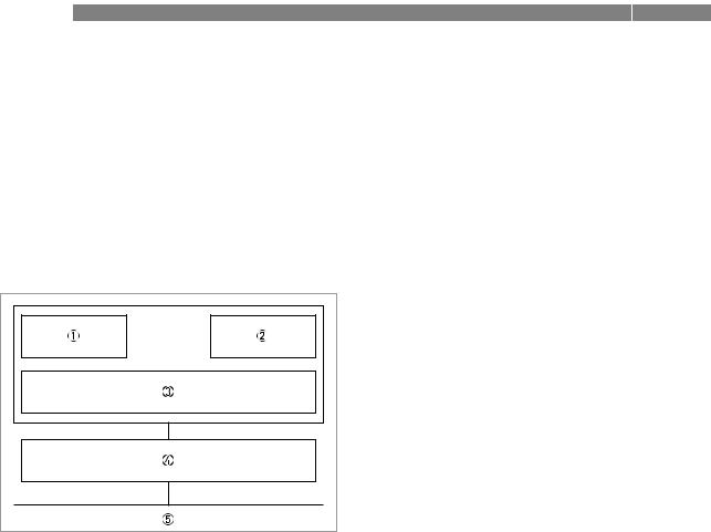
4.2 Description of the FF block system
The Foundation Fieldbus is a Local Area Network (LAN) for connecting field devices like sensors and actuators. One of the main benefits of Foundation Fieldbus is line saving in comparison to the traditional 4...20 mA technology.
The different device functions are implemented in a block-based scheme within a user application. In this block scheme, a distinction is made between the Resource Block, Transducer Block and Function Block.
1Resource Block (RB)
2Transducer Block (TB)
3Function Block (FB)
4Device FF communication
5Foundation Fieldbus
4.3Used abbreviations
AI |
Analogue Input Block |
|
|
IT |
Integrator Block |
|
|
PID |
Proportional Integral Derivate Block |
|
|
RB |
Resource Block |
|
|
TB |
Transducer Block |
|
|
R |
Read |
|
|
W |
Write |
|
|
R/W |
Read and Write |
|
|
BLK |
Block mode |
|
|
MAN |
Manual mode |
|
|
Mix |
Mix mode (R, W and R/W) |
|
|
Auto |
Automatic mode |
|
|
OOS |
Out Of Service mode |
|
|
OD |
Object Directory |
|
|
SP |
Set Point |
|
|
IV |
Initial Value |
|
|
PV |
Process Value (factory settings) |
|
|
10 |
www.krohne.com |
02/2012 - 4001702901 - AD IFC 100 FF R01 en |
|
|
OPERATION 4 |
|
IFC 100 |
|
|
|
|
4.4 Resource Block (RB)
The following tables list the Resource Block parameters in alphabetical order.
It describes characteristics of the Fieldbus device (e.g. device name, serial number, etc.) and is not included in the functional tasks of the signal converter for FF.
The following tables contain short parameter description, factory settings (Initial Value (IV)) and possible settings.
4.4.1 Foundation Fieldbus parameters for Resource Block
Parameter |
Access |
Description and settings |
Initial Value |
Subelement |
|
|
|
|
|
|
|
ALERT_KEY |
R/W |
The identification number of the plant unit. This information |
0 |
Alert Key |
|
may be used in the host for sorting alarms, etc. |
|
|
|
|
|
|
|
Setting: |
|
|
|
1...255 |
|
|
|
|
|
BLOCK_ERR |
R |
This parameter reflects the error status associated with the |
OOS |
Block Error |
|
hardware or software components associated with a block. It |
|
|
|
is a bit string, so that multiple errors may be shown. |
|
|
|
|
|
|
|
Setting: |
|
|
|
• Other: Non-specific error active |
|
|
|
• Block Configuration: Error detected in block configuration |
|
|
|
• Link Configuration: Error detected in link configuration |
|
|
|
• Simulation Active: Simulation enabled in this block |
|
|
|
• Local Override: Output tracking of faultstate active |
|
|
|
• Device Fault State: Device faultstate set |
|
|
|
• Device Maintenance: Device needs maintenance soon |
|
|
|
• Input Failure: Process variable has bad status |
|
|
|
• Output Failure: Failure detected in output hardware |
|
|
|
• Memory Failure: Memory error detected |
|
|
|
• Lost Static Data: Static parameters cannot be recovered |
|
|
|
• Lost NV Data: Non-volatile parameters cannot be recovered |
|
|
|
• Readback Check: Failure detected in READBACK |
|
|
|
• Maintenance Needed: Device NEEDS maintenance NOW |
|
|
|
• Power Up: Recovery from power failure |
|
|
|
• Out Of Service: Block actual mode is out of service |
|
|
|
|
|
MODE_BLK |
|
The actual, target, permitted and normal modes of the block. |
- |
Block Mode |
|
|
|
|
|
|
|
TARGET |
R/W |
This is the mode requested by the operator. Only one mode |
OOS |
Target |
|
from those allowed by the permitted mode parameter may be |
|
|
|
requested |
|
|
|
|
|
|
|
Setting: |
|
|
|
Auto / OOS |
|
|
|
|
|
ACTUAL |
R |
This is the current mode of the block, which may differ from |
OOS |
Actual |
|
the target based on operating conditions. Its value is |
|
|
|
calculated as part of block execution. |
|
|
|
|
|
|
|
Setting: |
|
|
|
Auto / OOS |
|
|
|
|
|
PERMITTED |
R/W |
Defines the mode which are allowed for an instance of the |
Auto or OOS |
Permitted |
|
block.The permitted mode is configured based on application |
|
|
|
requirement |
|
|
|
|
|
|
|
Setting: |
|
|
|
Auto / OOS |
|
|
|
|
|
02/2012 - 4001702901 - AD IFC 100 FF R01 en |
www.krohne.com |
11 |

4 OPERATION |
|
|
IFC 100 |
|
||
|
|
|
|
|
|
|
Parameter |
|
Access |
Description and settings |
Initial Value |
|
|
Subelement |
|
|
|
|
|
|
|
|
|
|
|
|
|
NORMAL |
|
R/W |
This is the mode which the block should be set to during |
Auto |
|
|
Normal |
|
|
normal operating conditions. |
|
|
|
|
|
|
|
|
|
|
|
|
|
Setting: |
|
|
|
|
|
|
Auto / OOS |
|
|
|
|
|
|
|
|
|
|
ST_REV |
|
R |
The revision level of the static data associated with the |
0 |
|
|
Static Revision |
|
|
function block. The revision value will be incremented each |
|
|
|
|
|
|
time a static parameter value in the block is changed. |
|
|
|
|
|
|
|
|
|
|
|
|
|
Setting: |
|
|
|
|
|
|
0...65535 |
|
|
|
|
|
|
|
|
|
|
STRATEGY |
|
R/W |
The strategy field can be used to identify grouping of blocks. |
0 |
|
|
Strategy |
|
|
This data is not checked or processed by the block. |
|
|
|
|
|
|
|
|
|
|
|
|
|
Setting: |
|
|
|
|
|
|
0...65535 |
|
|
|
|
|
|
|
|
|
|
TAG_DESC |
|
R/W |
The user description of the intended application of the block. |
blanks |
|
|
Tag Description |
|
|
|
|
|
|
|
|
Setting: |
|
|
|
|
|
|
|
|
|
|
|
|
|
|
≤32 digits |
|
|
|
|
|
|
|
|
|
|
ACK_OPTION |
|
R/W |
Selection of whether alarms associated with the function |
Uninitialized |
|
|
Acknowledge Option |
|
|
block will be automatically acknowledged. |
|
|
|
|
|
|
|
|
|
|
|
|
|
Setting: |
|
|
|
|
|
|
Disc Alm Auto Ack / Block Alm Auto Ack / Fail Alm Auto Ack / |
|
|
|
|
|
|
Off Spec Alm Auto Ack / Maint Alm Auto Ack / |
|
|
|
|
|
|
Check Alm Auto Ack |
|
|
|
|
|
|
|
|
|
|
ALARM_SUM |
|
|
The current alert status, unacknowledged states, unreported |
- |
|
|
Alarm Summary |
|
|
states and disabled states of the alarms associated with the |
|
|
|
|
|
|
function block. |
|
|
|
|
|
|
|
|
|
|
CURRENT |
|
R |
The active status of each alarm. |
Uninitialized |
|
|
Current |
|
|
|
|
|
|
|
|
Setting: |
|
|
|
|
|
|
|
|
|
|
|
|
|
|
Discrete Alarm / Block Alarm / Fail Alarm / Off Spec Alarm / |
|
|
|
|
|
|
Maintenace Alarm / Check Alarm |
|
|
|
|
|
|
|
|
|
|
UNACKNOWLEDGED |
|
R |
The unacknowledged state of each alarm |
Uninitialized |
|
|
Unacknowledged |
|
|
|
|
|
|
|
|
Setting: |
|
|
|
|
|
|
|
|
|
|
|
|
|
|
Disc Alm Unack / Block Alm Unack / Fail Alm Unack / |
|
|
|
|
|
|
Off Spec Alm Unack / Maint Alm Unack / Check Alm Unack |
|
|
|
UNREPORTED |
|
R |
The unreported status of each alarm. |
Uninitialized |
|
|
Unreported |
|
|
|
|
|
|
|
|
Setting: |
|
|
|
|
|
|
|
|
|
|
|
|
|
|
Disc Alm Unrep / Block Alm Unrep / Fail Alm Unrep / |
|
|
|
|
|
|
Off Spec Alm Unrep / Maint Alm Unrep / Check Alm Unrep |
|
|
|
DISABLED |
|
R/W |
The disabled state of each alarm |
Uninitialized |
|
|
Disabled |
|
|
|
|
|
|
|
|
Setting: |
|
|
|
|
|
|
|
|
|
|
|
|
|
|
Disc Alm Disabled / Block Alm Disabled / Fail Alm Disabled / |
|
|
|
|
|
|
Off Spec Alm Disabled / Maint Alm Disabled / Check Alm |
|
|
|
|
|
|
Disabled |
|
|
|
BLOCK_ALM |
|
|
The block alarm is used for all configuration, hardware, |
- |
|
|
Block Alarm |
|
|
connection failure or system problems in the block. The cause |
|
|
|
|
|
|
of the alert is entered in the subcode field. The first alert to |
|
|
|
|
|
|
become active will set the "Active" status in the "Status" |
|
|
|
|
|
|
attribute. As soon as the "Unreported" status is cleared by the |
|
|
|
|
|
|
alert reporting task, another block alert may be reported |
|
|
|
|
|
|
without clearing the "Active" status, if the subcode has |
|
|
|
|
|
|
changed. |
|
|
|
|
|
|
|
|
|
|
12 |
www.krohne.com |
02/2012 - 4001702901 - AD IFC 100 FF R01 en |

|
|
OPERATION 4 |
|
IFC 100 |
|
|
|
|
Parameter |
Access |
Description and settings |
Initial Value |
Subelement |
|
|
|
|
|
|
|
UNACKNOWLEDGED |
R/W |
A discrete enumeration which is set to "Unacknowledged" |
Uninitialized |
Unacknowledged |
|
when an alarm occurs, and set to "Acknowledged" by a write |
|
|
|
from a human interface device or other entity which can |
|
|
|
acknowledge that the alarm/event has been noticed. |
|
|
|
|
|
|
|
Setting: |
|
|
|
Uninitialized / Acknowledged / Unacknowledged |
|
|
|
|
|
ALARM_STATE |
R |
A discrete enumeration which gives an indication of whether |
Uninitialized |
Alarm State |
|
the alert is active and whether it has been reported. |
|
|
|
|
|
|
|
Setting: |
|
|
|
Uninitialized / Clear - reported / Clear - not reported / Active - |
|
|
|
reported / Active - not reported |
|
|
|
|
|
TIME_STAMP |
R |
The time when evaluation of the block was started and a |
Uninitialized |
Time Stamp |
|
change in alarm/event state was detected that is unreported. |
|
|
|
The time stamp value will be maintained constant until alert |
|
|
|
confirmation has been received - even if another change of |
|
|
|
state occurs. |
|
|
|
|
|
|
|
Setting: |
|
|
|
MM / DD / YY (Month / Day / Year) |
|
|
|
HH:MM:SS (Hour:Minute:Second) |
|
|
|
|
|
SUB_CODE |
R |
An enumeration specifying the cause of the alert to be |
Other |
Subcode |
|
reported. |
|
|
|
|
|
|
|
Setting: |
|
|
|
Other / Block Configuration / Link Configuration / Simulation |
|
|
|
Active / Local Override / Device Fault State / Device |
|
|
|
Maintenance / Input Failure / Output Failure / Memory |
|
|
|
Failure / Lost Static Data / Lost NV Data / Readback Check / |
|
|
|
Maintenance Needed / Power Up / Out Of Service |
|
|
|
|
|
VALUE |
R |
The value of the associated parameter at the time the alert |
0 |
Value |
|
was detected. |
|
|
|
|
|
|
|
Setting: |
|
|
|
0...255 |
|
|
|
|
|
CLR_FSTATE |
R/W |
Writing a "Clear" to this parameter will clear the device fault |
Off |
Clear Fault State |
|
state if the field condition, if any, has cleared. |
|
|
|
|
|
|
|
Setting: |
|
|
|
Uninitialized / Off / Clear |
|
|
|
|
|
CONFIRM_TIME |
R/W |
The minimum time between retries of alert reports. |
640000 |
Confirm Time |
|
|
|
|
Setting: |
|
|
|
|
|
|
|
|
0...4294967295 in [1/32 ms] |
|
|
|
|
|
CYCLE_SEL |
R/W |
Used to select the block execution method for this resource. |
Uninitialized |
Cycle Selection |
|
|
|
|
Setting: |
|
|
|
|
|
|
|
|
Scheduled / Block execution |
|
|
|
|
|
CYCLE_TYPE |
R |
Identifies the block execution methods available for this |
Scheduled or |
Cycle Type |
|
resource. |
Block execution |
|
|
Setting: |
|
|
|
Scheduled / Block execution |
|
DD_RESOURCE |
R |
String identifying the tag of the resource which contains the |
blanks |
DD Resource |
|
Device Description for this resource. |
|
|
|
≤32 digits |
|
|
|
|
|
DD_REV |
R |
Revision of the DD associated with the resource - used by an |
Dependent on |
DD Revision |
|
interface device to locate the DD file for the resource. |
device version |
|
|
|
|
|
|
Setting: |
|
|
|
Dependent on device version |
|
|
|
|
|
02/2012 - 4001702901 - AD IFC 100 FF R01 en |
www.krohne.com |
13 |

4 OPERATION |
|
|
IFC 100 |
|
||
|
|
|
|
|
|
|
Parameter |
|
Access |
Description and settings |
Initial Value |
|
|
Subelement |
|
|
|
|
|
|
|
|
|
|
|
|
|
DEV_REV |
|
R |
Manufacturer revision number associated with the resource - |
Dependent on |
|
|
Device Revision |
|
|
used by an interface device to locate the DD file for the |
device version |
|
|
|
|
|
resource. |
|
|
|
|
|
|
|
|
|
|
|
|
|
Setting: |
|
|
|
|
|
|
Dependent on device version |
|
|
|
|
|
|
|
|
|
|
DEV_TYPE |
|
R |
Manufacturer's model number associated with the resource - |
IFC100 |
|
|
Device Type |
|
|
used by interface devices to locate the DD file for the |
|
|
|
|
|
|
resource. |
|
|
|
|
|
|
|
|
|
|
|
|
|
Setting: |
|
|
|
|
|
|
IFC100 |
|
|
|
|
|
|
|
|
|
|
FAULT_STATE |
|
R |
Condition set by loss of communication to an output block, |
Clear |
|
|
Fault State |
|
|
failure promoted to an output block or a physical contact. |
|
|
|
|
|
|
When fault state condition is set, then output function blocks |
|
|
|
|
|
|
will perform their "FSTATE" actions. |
|
|
|
|
|
|
|
|
|
|
|
|
|
Setting: |
|
|
|
|
|
|
Uninitialized / Clear / Active |
|
|
|
|
|
|
|
|
|
|
FEATURES |
|
R |
Used to shows supported resource block options. |
Reports / |
|
|
Features |
|
|
|
Soft W Lock / |
|
|
|
|
Setting: |
|
|
||
|
|
|
MVC Report |
|
|
|
|
|
|
Reports / Soft W Lock / MVC Report Distribution supported / |
|
|
|
|
|
|
Distribution |
|
|
|
|
|
|
MVC Publishing/Subscribing supported / Multi-bit Alarm (Bit- |
|
|
|
|
|
|
supported / |
|
|
|
|
|
|
Alarm) Support |
|
|
|
|
|
|
MVC |
|
|
|
|
|
|
|
Publishing/Subscri |
|
|
|
|
|
|
bing supported/ |
|
|
|
|
|
|
Multi-bit Alarm |
|
|
|
|
|
|
(Bit-Alarm) |
|
|
|
|
|
|
Support |
|
|
|
|
|
|
|
|
|
FEATURES_SEL |
|
R/W |
Used to select resource block options. |
Reports / |
|
|
Features Selection |
|
|
|
Soft W Lock |
|
|
|
|
Setting: |
|
|
||
|
|
|
|
|
|
|
|
|
|
Reports / Soft W Lock / MVC Report Distribution supported / |
|
|
|
|
|
|
MVC Publishing/Subscribing supported / Multi-bit Alarm (Bit- |
|
|
|
|
|
|
Alarm) Support |
|
|
|
|
|
|
|
|
|
|
FREE_SPACE |
|
R |
Percent of the memory available for further configuration. |
0.0 |
|
|
Free Space |
|
|
Zero in a preconfigured device. |
|
|
|
|
|
|
|
|
|
|
|
|
|
Setting: |
|
|
|
|
|
|
0.0…100.0 |
|
|
|
FREE_TIME |
|
R |
Percent of the block processing time that is free to process |
0.0 |
|
|
Free Time |
|
|
additional blocks. |
|
|
|
|
|
|
|
|
|
|
|
|
|
Setting: |
|
|
|
|
|
|
0.0…100.0 |
|
|
|
GRANT_DENY |
|
|
Options for controlling access of host computers and local |
- |
|
|
Grant Deny |
|
|
control panels to operating, tuning and alarm parameters of |
|
|
|
|
|
|
the block. |
|
|
|
GRANT |
|
R/W |
Depending on the philosophy of the plant, the operator or a |
Uninitialized |
|
|
Grant |
|
|
higher level device (HLD) or a local operator's panel (LOP) in |
|
|
|
|
|
|
the case of "Local", may turn on an item of the "Grant" |
|
|
|
|
|
|
attribute - "Program, Tune, Alarm or Local". |
|
|
|
|
|
|
Setting: |
|
|
|
|
|
|
Program / Tune / Alarm / Local / Operate |
|
|
|
DENY |
|
R/W |
The denied attribute is limited for use by a monitoring |
Uninitialized |
|
|
Deny |
|
|
application in an interface device and may not be changed by |
|
|
|
|
|
|
an operator. |
|
|
|
|
|
|
Setting: |
|
|
|
|
|
|
Program denied / Tune denied / Alarm denied / Local denied / |
|
|
|
|
|
|
Operate denied |
|
|
|
HARD_TYPES |
|
R |
The types of hardware available as channel numbers. |
Scalar input |
|
|
Hard Types |
|
|
|
|
|
|
|
|
|
|
|
|
|
14 |
www.krohne.com |
02/2012 - 4001702901 - AD IFC 100 FF R01 en |

|
|
OPERATION 4 |
|
IFC 100 |
|
|
|
|
Parameter |
Access |
Description and settings |
Initial Value |
Subelement |
|
|
|
|
|
|
|
ITK_VER |
R |
Major revision number of the interoperability test case used to |
5 |
ITK Version |
|
register this device. |
|
(Interoperatibility Test |
|
|
|
Kit) |
|
|
|
|
|
|
|
LIM_NOTIFY |
R/W |
Maximum number of unconfirmed alert notify messages |
20 |
Limit Notify |
|
allowed. |
|
|
|
|
|
|
|
Setting: |
|
|
|
0...255 |
|
|
|
|
|
MANUFAC_ID |
R |
Manufacturer identification number - used by an interface |
KROHNE |
Manufacturer ID |
|
device to locate the DD file for the resource. |
|
|
|
|
|
MAX_NOTIFY |
R |
Maximum number of unconfirmed alert notify messages |
20 |
Max Notify |
|
possible. |
|
|
|
|
|
|
|
Setting: |
|
|
|
0...255 |
|
|
|
|
|
MEMORY_SIZE |
R |
Available configuration memory in the empty resource. To be |
0 |
Memory Size |
|
checked before attempting a download. |
|
|
|
|
|
MIN_CYCLE_T |
R |
Time duration of the shortest cycle interval of which the |
6400 |
Minimium Cycle Time |
|
resource is capable. (in [1/32 ms]) |
|
|
|
|
|
NV_CYCLE_T |
R |
Interval between writing copies of NV parameters to non- |
256000 |
Nonvolatile Cycle |
|
volatile memory. Zero means never. (in [1/32 ms]) |
|
Time |
|
|
|
|
|
|
|
RESTART |
R/W |
Allows a manual restart to be initiated. Several degrees of |
Run |
Restart |
|
restart are possible. They are 1: Run, 2: Restart resource, |
|
|
|
3: Restart with defaults and 4: Restart processor. |
|
|
|
|
|
|
|
Setting: |
|
|
|
Uninitialized / Run / Resource / Defaults / Processor |
|
|
|
|
|
RS_STATE |
R |
State of the function block application state machine. |
Standby |
Resource State |
|
|
|
|
Setting: |
|
|
|
|
|
|
|
|
Uninitialized / Start_Restart / Initialization / Online Linking / |
|
|
|
Online / Standby / Failure |
|
|
|
|
|
SET_FSTATE |
R/W |
Allows the fault state condition to be manually initiated by |
Off |
Set Fault State |
|
selecting "Set". |
|
|
|
Setting: |
|
|
|
Off |
|
SHED_RCAS |
R/W |
Time duration at which to give up on computer writes to |
640000 |
Shed Remote Cascade |
|
function block RCAS locations. |
|
|
|
Setting: |
|
|
|
0...4294967295 in [1/32 ms] |
|
SHED_ROUT |
R/W |
Time duration at which to give up on computer writes to |
640000 |
Shed Remote Out |
|
function block Rout locations. |
|
|
|
Setting: |
|
|
|
0...4294967295 in [1/32 ms] |
|
TEST_RW |
|
R/write test parameter - used only for conformance testing. |
- |
Test R Write |
|
Note: Subelements 1---15 have no function! |
|
|
|
|
|
UPDATE_EVT |
|
This alert is generated by any change to the static data. |
- |
Update Event |
|
|
|
|
|
|
|
UNACKNOWLEDGED |
R/W |
A discrete enumeration which is set to "Unacknowledged" |
Uninitialized |
Unacknowledged |
|
when an update occurs, and set to "Acknowledged" by a write |
|
|
|
from a human interface device or other entity which can |
|
|
|
acknowledge that the alarm has been noticed. |
|
|
|
|
|
|
|
Setting: |
|
|
|
Uninitialized / Acknowledged / Unacknowledged |
|
|
|
|
|
02/2012 - 4001702901 - AD IFC 100 FF R01 en |
www.krohne.com |
15 |

4 OPERATION |
|
|
IFC 100 |
|
||
|
|
|
|
|
|
|
Parameter |
|
Access |
Description and settings |
Initial Value |
|
|
Subelement |
|
|
|
|
|
|
|
|
|
|
|
|
|
UPDATE_STATE |
|
R |
A discrete enumeration which gives an indication of whether |
Uninitialized |
|
|
Update State |
|
|
the alert has been reported. |
|
|
|
|
|
|
|
|
|
|
|
|
|
Setting: |
|
|
|
|
|
|
Uninitialized / Reported / Not reported |
|
|
|
|
|
|
|
|
|
|
TIME_STAMP |
|
R |
The time when evaluation of the block was started and a |
Uninitialized |
|
|
Time Stamp |
|
|
change in alarm/event state was detected that is unreported. |
|
|
|
|
|
|
The time stamp value will be maintained constant until alert |
|
|
|
|
|
|
confirmation has been received - even if another change of |
|
|
|
|
|
|
state occurs. |
|
|
|
|
|
|
|
|
|
|
|
|
|
Setting: |
|
|
|
|
|
|
MM / DD / YY (Month / Day / Year) |
|
|
|
|
|
|
HH:MM:SS (Hour:Minute:Second) |
|
|
|
|
|
|
|
|
|
|
STATIC_REVISION |
|
R |
The static revision of the block whose static parameter was |
0 |
|
|
Static Revision |
|
|
changed and is being reported. It is possible for the present |
|
|
|
|
|
|
value of static revision to be greater than this because static |
|
|
|
|
|
|
can be changed at any time. |
|
|
|
|
|
|
|
|
|
|
|
|
|
Setting: |
|
|
|
|
|
|
0…65535 |
|
|
|
RELATIVE_INDEX |
|
R |
The OD index of the static parameter whose change caused |
0 |
|
|
Relative Index |
|
|
this alert, minus the FB starting index. If the update event was |
|
|
|
|
|
|
caused by a write to multiple parameters at the same time, |
|
|
|
|
|
|
then this attribute will be zero. |
|
|
|
|
|
|
|
|
|
|
|
|
|
Setting: |
|
|
|
|
|
|
0…65535 |
|
|
|
WRITE_ALM |
|
|
This alert is generated if the write lock parameter is cleared. |
- |
|
|
Write Alarm |
|
|
|
|
|
|
|
|
|
|
|
|
|
UNACKNOWLEDGED |
|
R/W |
A discrete enumeration which is set to "Unacknowledged" |
Uninitialized |
|
|
Unacknowledged |
|
|
when an alarm occurs, and set to "Acknowledged" by a write |
|
|
|
|
|
|
from a human interface device or other entity which can |
|
|
|
|
|
|
acknowledge that the alarm/event has been noticed. |
|
|
|
|
|
|
|
|
|
|
|
|
|
Setting: |
|
|
|
|
|
|
Uninitialized / Acknowledged / Unacknowledged |
|
|
|
|
|
|
|
|
|
|
ALARM_STATE |
|
R |
A discrete enumeration which gives an indication of whether |
Uninitialized |
|
|
Alarm State |
|
|
the alert is active and whether it has been reported. |
|
|
|
|
|
|
|
|
|
|
|
|
|
Setting: |
|
|
|
|
|
|
Uninitialized / Clear - reported / Clear - not reported / |
|
|
|
|
|
|
Active - reported / Active - not reported |
|
|
|
|
|
|
|
|
|
|
TIME_STAMP |
|
R |
The time when evaluation of the block was started and a |
Uninitialized |
|
|
Time Stamp |
|
|
change in alarm/event state was detected that is unreported. |
|
|
|
|
|
|
The time stamp value will be maintained constant until alert |
|
|
|
|
|
|
confirmation has been received - even if another change of |
|
|
|
|
|
|
state occurs. |
|
|
|
|
|
|
Setting: |
|
|
|
|
|
|
MM / DD / YY (Month / Day / Year) |
|
|
|
|
|
|
HH:MM:SS (Hour:Minute:Second) |
|
|
|
Sub_Code |
|
R |
An enumeration specifying the cause of the alert to be |
Other |
|
|
Subcode |
|
|
reported. |
|
|
|
|
|
|
Setting: |
|
|
|
|
|
|
Other / Block Configuration / Link Configuration / Simulation |
|
|
|
|
|
|
Active / Local Override / Device Fault State / Device |
|
|
|
|
|
|
Maintenance / Input Failure / Output Failure / Memory |
|
|
|
|
|
|
Failure / Lost Static Data / Lost NV Data / Readback Check / |
|
|
|
|
|
|
Maintenance Needed / Power Up / Out Of Service |
|
|
|
VALUE |
|
R |
The value of the associated parameter at the time the alert |
State 0 |
|
|
Discrete Value |
|
|
was detected. |
|
|
|
|
|
|
Setting: |
|
|
|
|
|
|
Discrete State 0...16 |
|
|
|
|
|
|
|
|
|
|
16 |
www.krohne.com |
02/2012 - 4001702901 - AD IFC 100 FF R01 en |

|
|
OPERATION 4 |
|
IFC 100 |
|
|
|
|
Parameter |
Access |
Description and settings |
Initial Value |
Subelement |
|
|
|
|
|
|
|
WRITE_LOCK |
R/W |
If set, no writes from anywhere are allowed, except to clear |
Not locked |
Write Lock |
|
WRITE_LOCK. Block inputs will continue to be updated. |
|
|
|
|
|
|
|
Setting: |
|
|
|
Uninitialized / Not locked / Locked |
|
|
|
|
|
WRITE_PRI |
R/W |
Priority of the alarm generated by clearing the write lock. |
0 |
Write Priority |
|
|
|
|
Setting: |
|
|
|
|
|
|
|
|
0...15 |
|
|
|
|
|
02/2012 - 4001702901 - AD IFC 100 FF R01 en |
www.krohne.com |
17 |

4 OPERATION |
IFC 100 |
|
4.4.2 Manufacturer specific parameters of the signal converter for Resource Block
Parameter |
Access |
Description and settings |
Initial Value |
Subelement |
|
|
|
|
|
|
|
DEV_DESCRIPTION |
|
Describes some characteristics of the device. |
- |
Device Description |
|
|
|
|
|
|
|
DB_DEVICE |
R |
Device Data Base |
Current Data Base |
Data Base GDC |
|
|
|
|
|
|
|
C_NUMBER_DEVICE |
R |
C-number of the device. |
Current C-number |
C-Number Device |
|
|
|
|
|
|
|
C_NUMBER_ |
R |
Production order of complete meter. |
Current production |
PRODUCT |
|
|
order |
C-Number Production |
|
|
|
|
|
|
|
CONVERTER_MODEL |
R |
The model of converter. |
IFC100 |
Converter Model |
|
|
|
|
|
|
|
LOGICAL_PLACE |
R |
Setting: |
Standard |
Logical Place |
|
Error / Standard / Extended standard / Special |
|
|
|
|
|
SUPPLY_OPTION |
R |
Supply of sensor and electronics option. |
As ordered |
Supply/Option |
|
|
|
|
Setting: |
|
|
|
|
|
|
|
|
configuration error / unknown / 100…230 VAC + Ex / |
|
|
|
100…230 VAC / 100…230 VAC + Ex Virtual Ref / 100…230 VAC |
|
|
|
+ non Ex / 100…230 VAC / 100…230 VAC + non Ex Virtual Ref / |
|
|
|
12…24 VDC / 12…24 VDC + non Ex / 12…24 VDC + non Ex |
|
|
|
Virtual Ref / 24VAC/DC + Ex / 24 VAC/DC / 24 VAC/DC + Ex |
|
|
|
Virtual Ref / 24VAC/DC + non Ex |
|
|
|
|
|
DISPLAY_OPTION |
R |
Setting: |
As ordered |
Display |
|
configuration error or missing / Standard / Eastern Europe / |
|
|
|
Northern Europe / Southern Europe / Far East / Japanese / |
|
|
|
Chinese / Russian |
|
|
|
|
|
IO_SELECTION |
R |
Setting: |
As ordered |
IO1 Modular IO |
|
configuration error or missing / no IO selection / Basic IO / Exi |
|
|
|
IO: CurrOut pas + PO pas / Profibus PA / Foundation Fieldbus / |
|
|
|
Profibus DP / RS485 Modbus + PO pas |
|
|
|
|
|
IO_MODULE_A |
R |
Not used |
- |
IO2 Module Term.A |
|
|
|
|
|
|
|
IO_MODULE_B |
|
No used |
- |
IO2 Module Term.B |
|
|
|
|
|
|
|
DIAGNOSIS |
|
Detailed diagnosis of the device. |
- |
Diagnosis |
|
|
|
|
|
|
|
MEMORY_SUMMARY |
R |
Summary of self diagnosis. |
ok |
Memory Summary |
|
|
|
|
Setting: |
|
|
|
|
|
|
|
|
ok / Bit 8…15 not used / EEPROM / FRAM / FLASH / ROM |
|
|
|
application / ROM boot area / RAM ext / RAM int / Task Control |
|
FRAM_DIAG |
R |
Result of FRAM self diagnosis. |
ok |
FRAM Diagnosis |
|
|
|
|
Setting: |
|
|
|
|
|
|
|
|
ok / not supported action / unknown / busy / wait / first init / |
|
|
|
changed / bit 09 / parameter error / page error / chip error / |
|
|
|
write error / warning: inconsistent / warning: uncertain / |
|
|
|
warning: write cycles / warning: one header / ok, page high |
|
work_LOAD |
R |
Work load of the processor. |
Current work load |
Work load |
|
|
|
18 |
www.krohne.com |
02/2012 - 4001702901 - AD IFC 100 FF R01 en |

|
|
OPERATION 4 |
|
IFC 100 |
|
|
|
|
DIAGNOSIS_BLK |
|
Detailed diagnosis of the blocks. |
- |
Diagnosis Block |
|
|
|
|
|
|
|
RB_DIAG |
R |
Reason for bits set at BLK_ERR and other diagnosis. |
Current diagnosis |
RB |
|
|
|
|
Setting: |
|
|
|
|
|
|
|
|
Startup Device / RB: MODE_BLK.ACTUAL is OOS / Memory |
|
|
|
failure / Operating System / new : ID , DEV_TYPE , SNR / |
|
|
|
no GDC Communication / Startup GDC, data invalid / Startup |
|
|
|
Sensor, data valid / C-Number doesn't match to FF Software / |
|
|
|
Hardware changed, Craw != C detected / Data Base doesn't |
|
|
|
match to FF Software / MODE_BLK.PERMITTED doesn't |
|
|
|
include Auto / MODE_BLK.TARGET is set OOS / GDC bold F |
|
|
|
message / GDC F message / Write from GDC to RB/TB doesn't |
|
|
|
work / GDC Mfr unknown / GDC serial number / Boardinfo |
|
|
|
incomplete or corrupt / action : write from GDC to RB/TB / |
|
|
|
GDC W : no, M : no / GDC W : no, M : some / |
|
|
|
GDC W : some, M : no / GDC W : no, M : all / |
|
|
|
GDC W : all, M : no / GDC W : some, M : some / |
|
|
|
GDC W : some, M : all / GDC W : all, M : some / |
|
|
|
GDC Communication few loss / RS_STATE is not On-Line / |
|
|
|
simulation active / SET_FSTATE was set / unknown reason / |
|
|
|
ok |
|
|
|
|
|
TB_DIAG |
R |
Reason for bits at BLK-ERR and other diagnosis. |
Current diagnosis |
TB |
|
|
|
|
Setting: |
|
|
|
|
|
|
|
|
Startup Device / RB : MODE_BLK.ACTUAL is OOS / Memory |
|
|
|
failure / no GDC Communication / Startup GDC, data invalid / |
|
|
|
Startup Sensor, data valid / Data Base doesn't match to FF |
|
|
|
Software / MODE_BLK.PERMITTED doesn't include Auto / |
|
|
|
MODE_BLK.TARGET is set OOS / GDC bold F message / GDC F |
|
|
|
message / Write from GDC to RB/TB doesn't work / Sensor |
|
|
|
serial number / Sensor calibration date / GDC unit not |
|
|
|
convertible to TB.prim_val / prim_val is outside range / |
|
|
|
action : write from GDC to RB/TB / GDC Communication few |
|
|
|
loss / No unit of GDC / GDC unit can't be converted to |
|
|
|
TB.prim_range / a GDC value was not received / a GDC short |
|
|
|
status is fatal or warn2 / PRIMARY_VALUE_1.status is |
|
|
|
Uncertain / unknown reason / ok |
|
|
|
|
|
AI1/2/3_DIAG |
R |
Reason for Out.status not good, bits at BLK-ERR and other |
Current diagnosis |
AI1/2/3 |
|
diagnosis. |
|
|
|
|
|
|
|
Setting: |
|
|
|
Startup Device / RB : MODE_BLK.ACTUAL is OOS / Memory |
|
|
|
failure / no schedule / period of execution / period of |
|
|
|
execution too large / MODE_BLK.PERMITTED doesn't include |
|
|
|
Auto / MODE_BLK.TARGET is set OOS / MODE_BLK.TARGET is |
|
|
|
set MAN / MODE_BLK.ACTUAL is MAN, Startup to Auto / |
|
|
|
CHANNEL is uninitialized / UNIT of CHANNEL selected |
|
|
|
TB.prim_val not convertible to XD UNIT / XD_SCALE : |
|
|
|
difference between EU_100 and EU_0 is too less / OUT_SCALE |
|
|
|
: difference between EU_100 and EU_0 is too less / L_TYPE is |
|
|
|
uninitialized / L_TYPE is direct , XD_SCALE is not equal |
|
|
|
OUT_SCALE / IO-OPTS no unit conversion, XD UNIT doesnt´t |
|
|
|
match to UNIT of TB.prim_val / SIMULATE_STATUS is not |
|
|
|
Good, Simulation is active / SIMULATE_STATUS limitted, |
|
|
|
STATUS_OPTS is set, Simulation active / Simulation is active / |
|
|
|
Transducer Block MODE_BLK.ACTUAL is OOS / CHANNEL |
|
|
|
selected TB.prim_val.status is Bad / TB.prim_val.status is |
|
|
|
limitted, STATUS_OPTS is set / CHANNEL selected |
|
|
|
TB.prim_val.status is Uncertain / OUT.value exceeds |
|
|
|
OUT_SCALE / unknown reason / ok |
|
02/2012 - 4001702901 - AD IFC 100 FF R01 en |
www.krohne.com |
19 |

4 OPERATION |
|
|
IFC 100 |
|
||
|
|
|
|
|
|
|
PID_DIAG |
|
R |
Reason for OUT.status not good, bits at BLK_ERR and other |
Current diagnosis |
|
|
PID |
|
|
diagnosis. |
|
|
|
|
|
|
Setting: |
|
|
|
|
|
|
Startup Device / RB : MODE_BLK.ACTUAL is OOS / Memory |
|
|
|
|
|
|
failure / no schedule / period of execution / period of |
|
|
|
|
|
|
execution too large / MODE_BLK.PERMITTED doesn't include |
|
|
|
|
|
|
Auto / MODE_BLK.TARGET is set OOS / MODE_BLK.TARGET is |
|
|
|
|
|
|
set MAN / MODE_BLK.ACTUAL is MAN, Startup to Auto / |
|
|
|
|
|
|
BYPASS is uninitialized / SHED_OPT is uninitialized / |
|
|
|
|
|
|
PV_SCALE : EU_100 <= EU_0 / OUT_SCALE : EU_100 <= |
|
|
|
|
|
|
EU_0 / TRK_SCALE : EU_100 <= EU_0 / FF_SCALE : EU_100 |
|
|
|
|
|
|
<= EU_0 / unknown reason / ok |
|
|
|
IT1/2_DIAG |
|
R |
Reason for OUT.status not good, bits at BLK_ERR and other |
Current diagnosis |
|
|
IT1/2 |
|
|
diagnosis . |
|
|
|
|
|
|
|
|
|
|
|
|
|
Setting: |
|
|
|
|
|
|
Startup Device / RB : MODE_BLK.ACTUAL is OOS / Memory |
|
|
|
|
|
|
failure / no schedule / period of execution / period of |
|
|
|
|
|
|
execution too large / MODE_BLK.PERMITTED doesn't include |
|
|
|
|
|
|
Auto / MODE_BLK.TARGET is set OOS / MODE_BLK.TARGET is |
|
|
|
|
|
|
set MAN / MODE_BLK.ACTUAL is MAN, Startup to Auto / |
|
|
|
|
|
|
INTEG_TYPE is uninitialized / IN_1 and IN_2 are not |
|
|
|
|
|
|
connected / TIME_UNIT1 and TIME_UNIT2 are uninitialized / |
|
|
|
|
|
|
CLOCK_PER <= period of execution / TIME_UNIT1 is |
|
|
|
|
|
|
uninitialized / TIME_UNIT2 is uninitialized / IN_1.status is |
|
|
|
|
|
|
Bad / IN_2.status is Bad / IN_1.value is NaN or INF / |
|
|
|
|
|
|
IN_2.value is NaN or INF / PCT_INCL < UNCERT_LIM / |
|
|
|
|
|
|
PCT_INCL < GOOD_LIM / PULSE_VAL1 and PULSE_VAL2 are |
|
|
|
|
|
|
0 / TOTAL_SP is 0 : cyclic reset / unknown reason / ok |
|
|
|
|
|
|
|
|
|
|
20 |
www.krohne.com |
02/2012 - 4001702901 - AD IFC 100 FF R01 en |
 Loading...