


IFC-100

Signal converter for electromagnetic flowmeters
Electronic revision:
ER 3.1.x
IFC 100
IFC 100IFC 100
IFC 100
Handbook
HandbookHandbook
Handbook
© KROHNE 07/2014 - 4000041005 - MA IFC 100 R05 en
The documentation is only complete when used in combination with the relevant
documentation for the flow sensor.

All rights reserved. It is prohibited to reproduce this documentation, or any part thereof, without
the prior written authorisation of KROHNE Messtechnik GmbH.
Subject to change without notice.
2
www.krohne.com 07/2014 - 4000041005 - MA IFC 100 R05 en
Copyright 2014 by
KROHNE Messtechnik GmbH - Ludwig-Krohne-Str. 5 - 47058 Duisburg (Germany)
: IMPRINT :::::::::::::::::::::::::::::::::::::::

CONTENTS
3
www.krohne.com07/2014 - 4000041005 - MA IFC 100 R05 en
IFC 100
1 Safety instructions 6
1.1 Software history ............................................................................................................... 6
1.2 Intended use ..................................................................................................................... 7
1.3 Certifications .................................................................................................................... 7
1.4 Safety instructions from the manufacturer ..................................................................... 8
1.4.1 Copyright and data protection ................................................................................................ 8
1.4.2 Disclaimer ............................................................................................................................... 8
1.4.3 Product liability and warranty ................................................................................................ 9
1.4.4 Information concerning the documentation........................................................................... 9
1.4.5 Warnings and symbols used................................................................................................. 10
1.5 Safety instructions for the operator............................................................................... 10
2 Device description 11
2.1 Scope of delivery............................................................................................................. 11
2.2 Device description .......................................................................................................... 12
2.3 Nameplates .................................................................................................................... 13
2.3.1 Nameplate (example)............................................................................................................ 13
3 Installation 14
3.1 General notes on installation ......................................................................................... 14
3.2 Storage ........................................................................................................................... 14
3.3 Transport ........................................................................................................................ 14
3.4 Installation specifications .............................................................................................. 14
3.5 Mounting of the compact version................................................................................... 15
3.6 Mounting the wall-mounted housing, remote version .................................................. 15
3.6.1 Wall mounting....................................................................................................................... 15
4 Electrical connections 17
4.1 Safety instructions.......................................................................................................... 17
4.2 Important notes on electrical connection...................................................................... 17
4.3 Electrical cables for remote device versions, notes...................................................... 18
4.3.1 Notes on signal cable A ........................................................................................................ 18
4.3.2 Notes on field current cable C.............................................................................................. 18
4.3.3 Requirements for signal cables provided by the customer ................................................. 19
4.4 Preparing the signal and field current cables ............................................................... 20
4.4.1 Signal cable A (type DS 300), construction........................................................................... 20
4.4.2 Preparing signal cable A, connection to signal converter ................................................... 21
4.4.3 Length of signal cable A........................................................................................................ 22
4.4.4 Preparing field current cable C, connection to signal converter......................................... 23
4.4.5 Preparing signal cable A, connection to measuring sensor................................................ 25
4.4.6 Preparing field current cable C, connection to measuring sensor ..................................... 26
4.5 Connecting the signal and field current cables............................................................. 27
4.5.1 Connecting the signal and field current cables to the signal converter, remote version... 28
4.5.2 Connection diagram for signal and field current cable ....................................................... 30
4.6 Grounding the measuring sensor .................................................................................. 31
4.6.1 Classical method................................................................................................................... 31

CONTENTS
4
www.krohne.com 07/2014 - 4000041005 - MA IFC 100 R05 en
IFC 100
4.7 Connecting the power supply......................................................................................... 32
4.8 Inputs and outputs, overview ......................................................................................... 34
4.8.1 Description of the CG number .............................................................................................. 34
4.8.2 Fixed, non-alterable output versions ................................................................................... 34
4.9 Description of the inputs and outputs............................................................................ 36
4.9.1 Current output ...................................................................................................................... 36
4.9.2 Pulse output and frequency output ...................................................................................... 37
4.9.3 Status output and limit switch .............................................................................................. 38
4.9.4 Control input ......................................................................................................................... 39
4.10 Electrical connection of the outputs ............................................................................ 40
4.10.1 Electrical connection of the outputs................................................................................... 40
4.10.2 Laying electrical cables correctly....................................................................................... 41
4.11 Connection diagrams of outputs .................................................................................. 41
4.11.1 Important notes................................................................................................................... 41
4.11.2 Description of the electrical symbols................................................................................. 42
4.11.3 Basic outputs....................................................................................................................... 43
4.11.4 Ex i outputs.......................................................................................................................... 47
4.11.5 HART
®
connection .............................................................................................................. 49
5 Start-up 50
5.1 Switching on the power .................................................................................................. 50
5.2 Starting the signal converter ......................................................................................... 50
6 Operation 51
6.1 Display and operating elements .................................................................................... 51
6.1.1 Display in measuring mode with 2 or 3 measured values ................................................... 52
6.1.2 Display for selection of sub-menu and functions, 3 lines.................................................... 52
6.1.3 Display when setting parameters, 4 lines ............................................................................ 53
6.1.4 Display when previewing parameters, 4 lines...................................................................... 53
6.2 Menu structure............................................................................................................... 54
6.3 Function tables ............................................................................................................... 56
6.3.1 Menu A, quick setup.............................................................................................................. 56
6.3.2 Menu B, test .......................................................................................................................... 58
6.3.3 Menu C, setup ....................................................................................................................... 60
6.3.4 Set free units......................................................................................................................... 76
6.4 Description of functions ................................................................................................. 76
6.4.1 Reset counter in the menu "quick setup" ............................................................................ 76
6.4.2 Deleting error messages in the menu "quick setup"........................................................... 77
6.5 Status messages and diagnostic information................................................................ 77
7 Service 82
7.1 Spare parts availability...................................................................................................82
7.2 Availability of services .................................................................................................... 82
7.3 Returning the device to the manufacturer..................................................................... 82
7.3.1 General information.............................................................................................................. 82
7.3.2 Form (for copying) to accompany a returned device............................................................ 83
7.4 Disposal .......................................................................................................................... 83

CONTENTS
5
www.krohne.com07/2014 - 4000041005 - MA IFC 100 R05 en
IFC 100
8 Technical data 84
8.1 Measuring principle........................................................................................................84
8.2 Technical data................................................................................................................. 85
8.3 Dimensions and weights ................................................................................................ 94
8.3.1 Housing ................................................................................................................................. 94
8.3.2 Mounting plate, wall-mounted version ................................................................................ 97
8.4 Flow tables ..................................................................................................................... 98
8.5 Measuring accuracy ..................................................................................................... 100
9 Description of HART interface 101
9.1 General description ...................................................................................................... 101
9.2 Software history ...........................................................................................................101
9.3 Connection variants...................................................................................................... 102
9.3.1 Point-to-Point connection - analogue / digital mode......................................................... 103
9.3.2 Multi-Drop connection (2-wire connection) ....................................................................... 104
9.3.3 Multi-Drop connection (3-wire connection) ....................................................................... 105
9.4 Outputs and HART
®
dynamic variables and device variables ..................................... 106
9.5 Parameter for the basic configuration......................................................................... 107
9.6 Field Communicator 375/475 (FC 375/475) ................................................................. 108
9.6.1 Installation .......................................................................................................................... 108
9.6.2 Operation............................................................................................................................. 108
9.6.3 Parameter for the basic configuration ............................................................................... 108
9.7 Asset Management Solutions (AMS)............................................................................ 109
9.7.1 Installation .......................................................................................................................... 109
9.7.2 Operation............................................................................................................................. 109
9.7.3 Parameter for the basic configuration ............................................................................... 109
9.8 Field Device Manager (FDM) ........................................................................................ 110
9.8.1 Installation .......................................................................................................................... 110
9.8.2 Operation............................................................................................................................. 110
9.9 Process Device Manager (PDM)................................................................................... 110
9.9.1 Installation .......................................................................................................................... 110
9.9.2 Operation............................................................................................................................. 111
9.9.3 Parameter for the basic configuration ............................................................................... 111
9.10 Field Device Tool / Device Type Manager (FDT / DTM) .............................................. 112
9.10.1 Installation ........................................................................................................................ 112
9.10.2 Operation........................................................................................................................... 112
9.11 Appendix A: HART
®
menu tree for Basic-DD ............................................................ 112
9.11.1 Overview Basic-DD menu tree (positions in menu tree).................................................. 113
9.11.2 Basic-DD menu tree (details for settings)........................................................................ 114
9.12 Appendix B: HART
®
menu tree for AMS .................................................................... 117
9.12.1 Overview AMS menu tree (positions in menu tree) .......................................................... 117
9.12.2 AMS menu tree (details for settings)................................................................................ 118
9.13 Appendix C: HART
®
menu tree for PDM.................................................................... 122
9.13.1 Overview PDM menu tree (positions in menu tree).......................................................... 122
9.13.2 PDM menu tree (details for settings) ............................................................................... 124
1 SAFETY INSTRUCTIONS
6
IFC 100
www.krohne.com 07/2014 - 4000041005 - MA IFC 100 R05 en
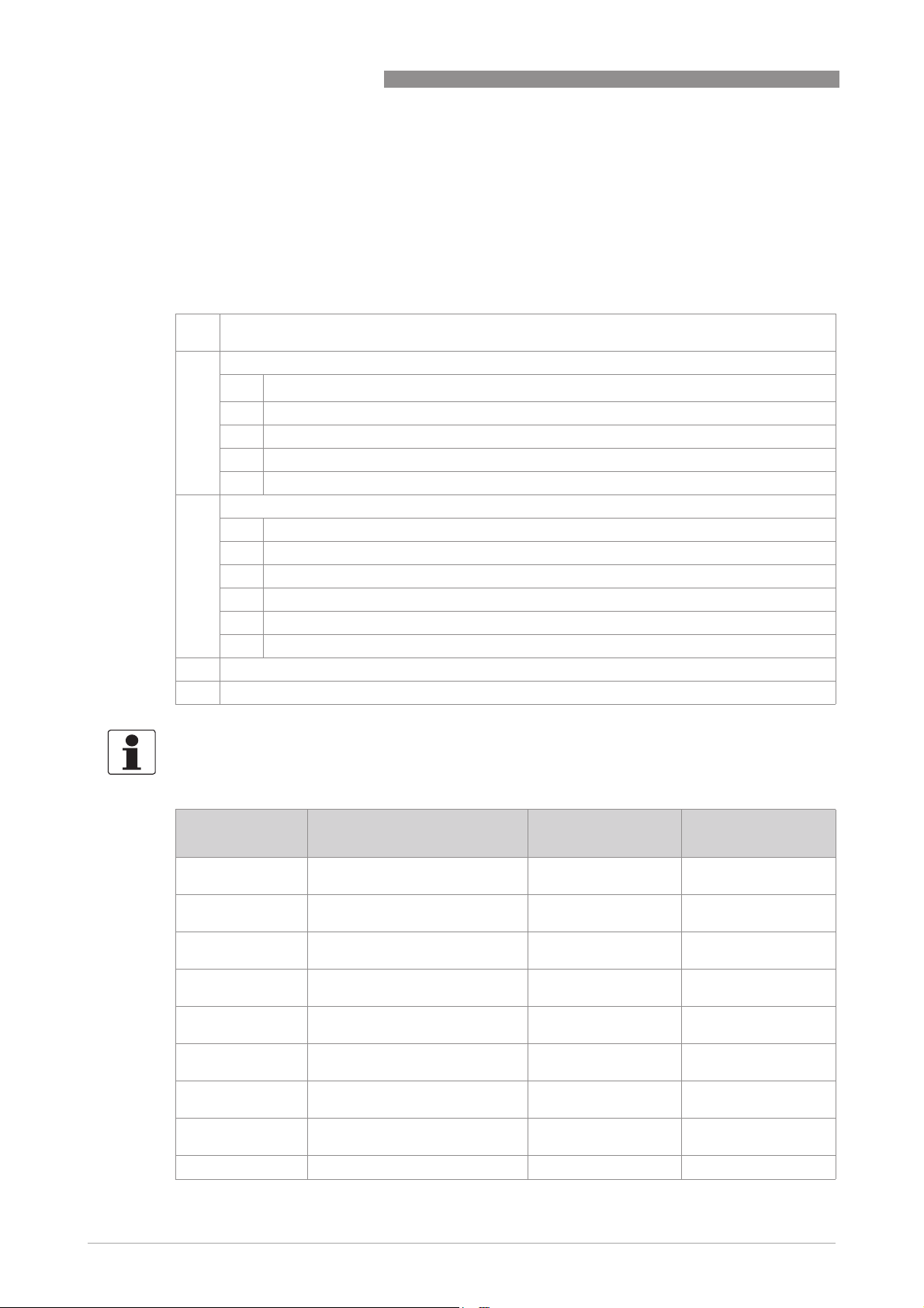
1.1 Software history
The "Electronic Revision" (ER) is consulted to document the revision status of electronic
equipment according to NE 53 for all GDC devices. It is easy to see from the ER whether
troubleshooting or larger changes in the electronic equipment have taken place and how that
has affected the compatibility.
Changes and effect on compatibility
1 Downwards compatible changes and fault repair with no effect on operation (e.g. spelling
mistakes on display)
2-_ Downwards compatible hardware and/or software change of interfaces:
H
HART
®
P PROFIBUS
F Foundation Fieldbus
M Modbus
X all interfaces
3-_ Downwards compatible hardware and/or software change of inputs and outputs:
I Current output
F, P Frequency / pulse output
S Status output
C Control input
CI Current input
X all inputs and outputs
4 Downwards compatible changes with new functions
5 Incompatible changes, i.e. electronic equipment must be changed.
INFORMATION!
In the table below, "x" is a placeholder for possible multi-digit alphanumeric combinations,
depending on the available version.
Release date Electronic Revision Changes and
compatibility
Documentation
2007-12-11 ER 2.0.0
(SW.REV. 2.00 (2.00))
- -
2008-02-29 ER 2.0.1
(SW.REV. 2.00 (2.00))
1 MA IFC 100 R03
2008-05-07 ER 2.0.2
(SW.REV. 2.00 (2.00))
1 MA IFC 100 R04
2008-06-27 ER 2.0.3
(SW.REV. 2.00 (2.00))
1 MA IFC 100 R04
2010-01-04 ER 2.0.4
(SW.REV. 2.00 (2.00))
1 MA IFC 100 R04
2010-01-04 ER 2.1.0
(SW.REV. 2.10 (3.00))
1; 2-H MA IFC 100 R04
2010-07-08 ER 2.1.1
(SW.REV. 2.11 (3.00))
1 MA IFC 100 R04
2011-12-12 ER 3.0.0
(SW.REV. 3.00 (4.00))
1; 2-X; 3-X, 5-S 1 MA IFC 100 R05
2013-04-26 ER 3.0.1 1 MA IFC 100 R05
SAFETY INSTRUCTIONS 1
7
IFC 100
www.krohne.com07/2014 - 4000041005 - MA IFC 100 R05 en
1.2 Intended use
The electromagnetic flowmeters are designed exclusively to measure the flow and conductivity
of electrically conductive, liquid media.
1.3 Certifications
The device fulfils the statutory requirements of the following EC directives:
• Low Voltage Directive 2006/95/EC
• EMC Directive 2004/108/EC
as well as
• EN 61010
• EMC specification acc. to EN 61326/A1
• NAMUR recommendations NE 21 and NE 43
The manufacturer certifies successful testing of the product by applying the CE marking.
2014-02-14 ER 3.0.2 1 MA IFC 100 R05
2014-08-01 ER 3.1.0 1; 2-H; 2-M; 3-F; 3-P;
3-C
MA IFC 100 R05
1 Incompatible change on status output: de-energised status reversed
Release date Electronic Revision Changes and
compatibility
Documentation
DANGER!
For devices used in hazardous areas, additional safety notes apply; please refer to the Ex
documentation.
WARNING!
If the device is not used according to the operating conditions (refer to chapter "Technical data"),
the intended protection could be affected.
CE marking
DANGER!
For devices used in hazardous areas, additional safety notes apply; please refer to the Ex
documentation.

1 SAFETY INSTRUCTIONS
8
IFC 100
www.krohne.com 07/2014 - 4000041005 - MA IFC 100 R05 en
1.4 Safety instructions from the manufacturer
1.4.1 Copyright and data protection
The contents of this document have been created with great care. Nevertheless, we provide no
guarantee that the contents are correct, complete or up-to-date.
The contents and works in this document are subject to copyright. Contributions from third
parties are identified as such. Reproduction, processing, dissemination and any type of use
beyond what is permitted under copyright requires written authorisation from the respective
author and/or the manufacturer.
The manufacturer tries always to observe the copyrights of others, and to draw on works created
in-house or works in the public domain.
The collection of personal data (such as names, street addresses or e-mail addresses) in the
manufacturer's documents is always on a voluntary basis whenever possible. Whenever
feasible, it is always possible to make use of the offerings and services without providing any
personal data.
We draw your attention to the fact that data transmission over the Internet (e.g. when
communicating by e-mail) may involve gaps in security. It is not possible to protect such data
completely against access by third parties.
We hereby expressly prohibit the use of the contact data published as part of our duty to publish
an imprint for the purpose of sending us any advertising or informational materials that we have
not expressly requested.
1.4.2 Disclaimer
The manufacturer will not be liable for any damage of any kind by using its product, including,
but not limited to direct, indirect or incidental and consequential damages.
This disclaimer does not apply in case the manufacturer has acted on purpose or with gross
negligence. In the event any applicable law does not allow such limitations on implied warranties
or the exclusion of limitation of certain damages, you may, if such law applies to you, not be
subject to some or all of the above disclaimer, exclusions or limitations.
Any product purchased from the manufacturer is warranted in accordance with the relevant
product documentation and our Terms and Conditions of Sale.
The manufacturer reserves the right to alter the content of its documents, including this
disclaimer in any way, at any time, for any reason, without prior notification, and will not be liable
in any way for possible consequences of such changes.

SAFETY INSTRUCTIONS 1
9
IFC 100
www.krohne.com07/2014 - 4000041005 - MA IFC 100 R05 en
1.4.3 Product liability and warranty
The operator shall bear responsibility for the suitability of the device for the specific purpose.
The manufacturer accepts no liability for the consequences of misuse by the operator. Improper
installation and operation of the devices (systems) will cause the warranty to be void. The
respective "Standard Terms and Conditions" which form the basis for the sales contract shall
also apply.
1.4.4 Information concerning the documentation
To prevent any injury to the user or damage to the device it is essential that you read the
information in this document and observe applicable national standards, safety requirements
and accident prevention regulations.
If this document is not in your native language and if you have any problems understanding the
text, we advise you to contact your local office for assistance. The manufacturer can not accept
responsibility for any damage or injury caused by misunderstanding of the information in this
document.
This document is provided to help you establish operating conditions, which will permit safe and
efficient use of this device. Special considerations and precautions are also described in the
document, which appear in the form of underneath icons.
1 SAFETY INSTRUCTIONS
10
IFC 100
www.krohne.com 07/2014 - 4000041005 - MA IFC 100 R05 en
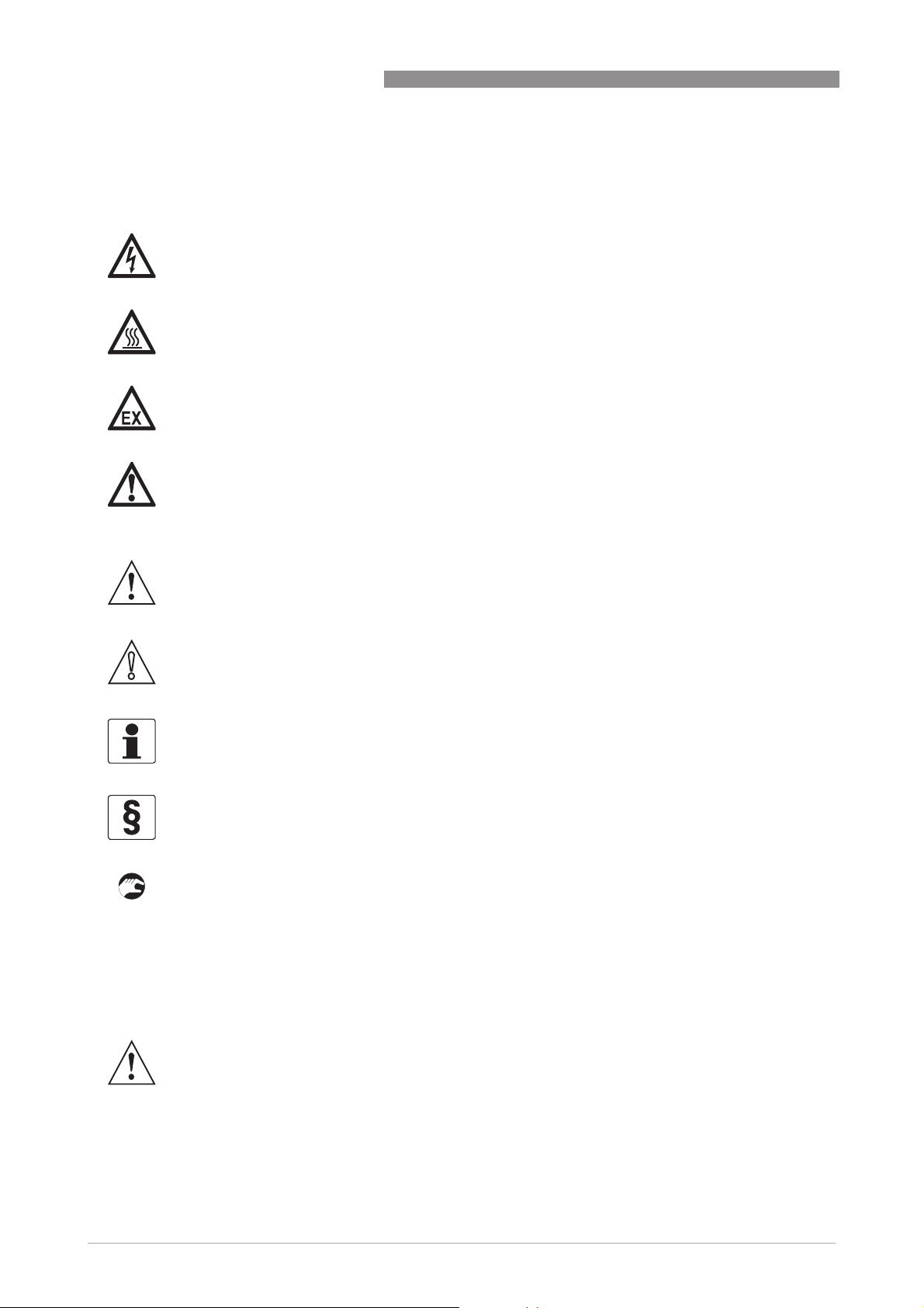
1.4.5 Warnings and symbols used
Safety warnings are indicated by the following symbols.
• HANDLING
HANDLINGHANDLING
HANDLING
This symbol designates all instructions for actions to be carried out by the operator in the
specified sequence.
i RESULT
RESULTRESULT
RESULT
This symbol refers to all important consequences of the previous actions.
1.5 Safety instructions for the operator
DANGER!
This warning refers to the immediate danger when working with electricity.
DANGER!
This warning refers to the immediate danger of burns caused by heat or hot surfaces.
DANGER!
This warning refers to the immediate danger when using this device in a hazardous atmosphere.
DANGER!
These warnings must be observed without fail. Even partial disregard of this warning can lead to
serious health problems and even death. There is also the risk of seriously damaging the device
or parts of the operator's plant.
WARNING!
Disregarding this safety warning, even if only in part, poses the risk of serious health problems.
There is also the risk of damaging the device or parts of the operator's plant.
CAUTION!
Disregarding these instructions can result in damage to the device or to parts of the operator's
plant.
INFORMATION!
These instructions contain important information for the handling of the device.
LEGAL NOTICE!
This note contains information on statutory directives and standards.
WARNING!
In general, devices from the manufacturer may only be installed, commissioned, operated and
maintained by properly trained and authorized personnel.
This document is provided to help you establish operating conditions, which will permit safe and
efficient use of this device.
DEVICE DESCRIPTION 2
11
IFC 100
www.krohne.com07/2014 - 4000041005 - MA IFC 100 R05 en
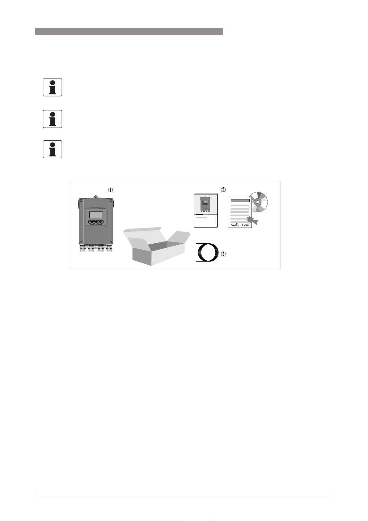
2.1 Scope of delivery
INFORMATION!
Inspect the packaging carefully for damages or signs of rough handling. Report damage to the
carrier and to the local office of the manufacturer.
INFORMATION!
Do a check of the packing list to make sure that you have all the elements given in the order.
INFORMATION!
Look at the device nameplate to ensure that the device is delivered according to your order.
Check for the correct supply voltage printed on the nameplate.
Figure 2-1: Scope of delivery
1 Device in the version as ordered
2 Documentation (calibration report, Quick Start, CD-ROM with product documentation for measuring sensor and signal
converter)
3 Signal cable (only for remote version)
2 DEVICE DESCRIPTION
12
IFC 100
www.krohne.com 07/2014 - 4000041005 - MA IFC 100 R05 en
2.2 Device description
Electromagnetic flowmeters are designed exclusively to measure the flow and conductivity of
electrically conductive, liquid media.
Your measuring device is supplied ready for operation. The factory settings for the operating
data have been made in accordance with your order specifications.
The following versions are available:
• Compact version (the signal converter is mounted directly on the measuring sensor)
• Remote version (electrical connection to the measuring sensor via field current and signal
cable)
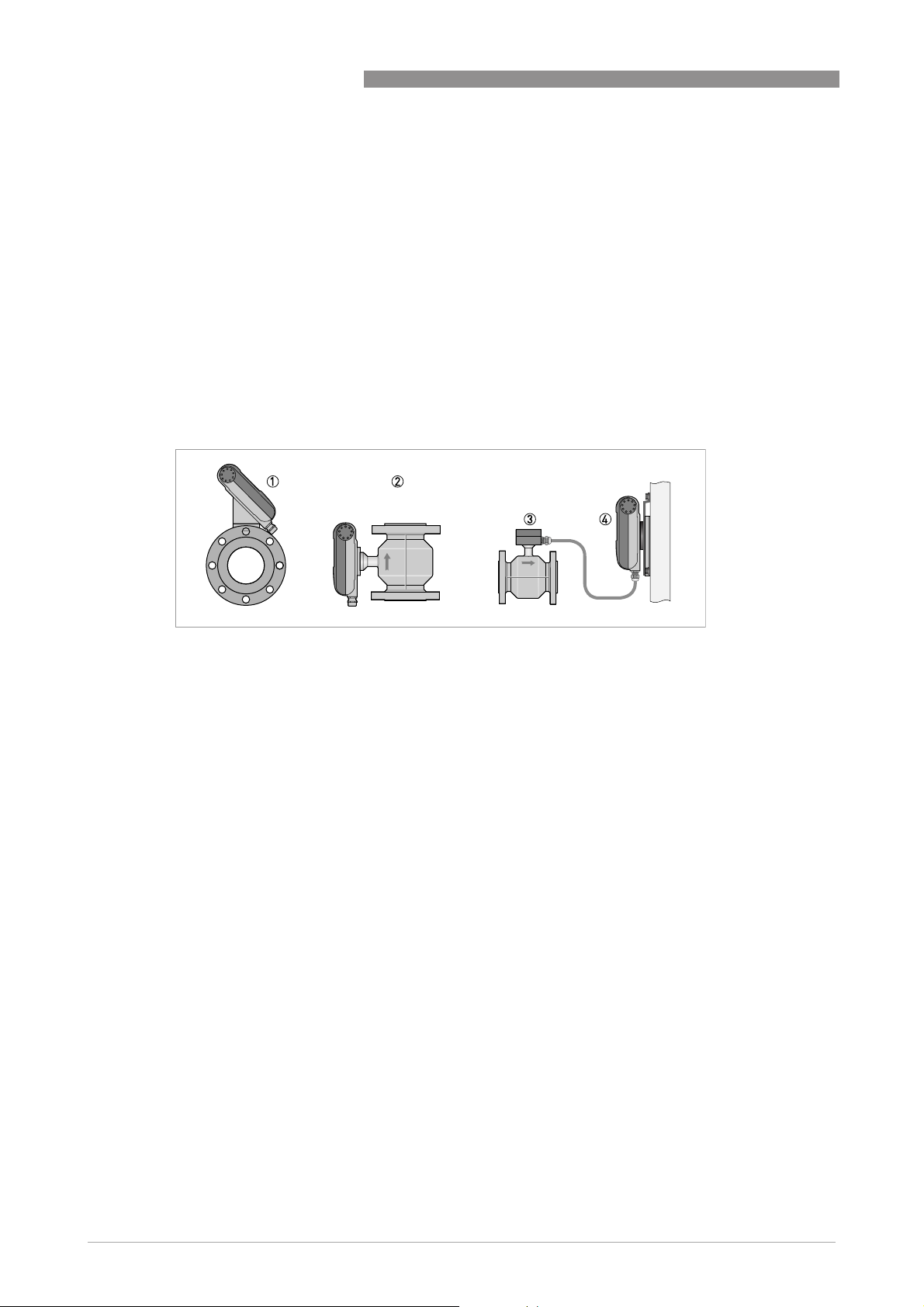
Figure 2-2: Device versions
1 Compact version as 45° version
2 Compact version as 0° version
3 Measuring sensor with connection box
4 Wall version
DEVICE DESCRIPTION 2
13
IFC 100
www.krohne.com07/2014 - 4000041005 - MA IFC 100 R05 en
2.3 Nameplates
2.3.1 Nameplate (example)
INFORMATION!
Look at the device nameplate to ensure that the device is delivered according to your order.
Check for the correct supply voltage printed on the nameplate.
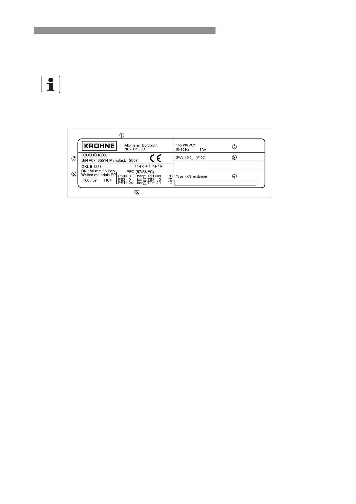
Figure 2-3: Example of a nameplate
1 Manufacturer
2 Power supply data
3 Software version
4 Tag name
5 Approvals-related pressure and temperature thresholds
6 GK/GKL values (measuring sensor constants); size (mm /inches); field frequency; protection category; materials of
wetted parts
7 Product designation, serial number and manufacturing date
3 INSTALLATION
14
IFC 100
www.krohne.com 07/2014 - 4000041005 - MA IFC 100 R05 en
3.1 General notes on installation
3.2 Storage
• Store the device in a dry, dust-free location.
• Avoid continuous direct sunlight.
• Store the device in its original packing.
• Storage temperature: -40...+70°C / -40...+158°F
3.3 Transport
Signal converter
• No special requirements.
Compact version
• Do not lift the device by the signal converter housing.
• Do not use lifting chains.
• To transport flange devices, use lifting straps. Wrap these around both process connections.
3.4 Installation specifications
INFORMATION!
Inspect the packaging carefully for damages or signs of rough handling. Report damage to the
carrier and to the local office of the manufacturer.
INFORMATION!
Do a check of the packing list to make sure that you have all the elements given in the order.
INFORMATION!
Look at the device nameplate to ensure that the device is delivered according to your order.
Check for the correct supply voltage printed on the nameplate.
INFORMATION!
The following precautions must be taken to ensure reliable installation.
•
Make sure that there is adequate space to the sides.
•
Protect the signal converter from direct sunlight and install a sun shade if necessary.
•
Signal converters installed in control cabinets require adequate cooling, e.g. by fan or heat
exchanger.
•
Do not expose the signal converter to intense vibrations. The measuring devices are tested
for a vibration level in accordance with IEC 68-2-64.
INSTALLATION 3
15
IFC 100
www.krohne.com07/2014 - 4000041005 - MA IFC 100 R05 en
3.5 Mounting of the compact version
3.6 Mounting the wall-mounted housing, remote version
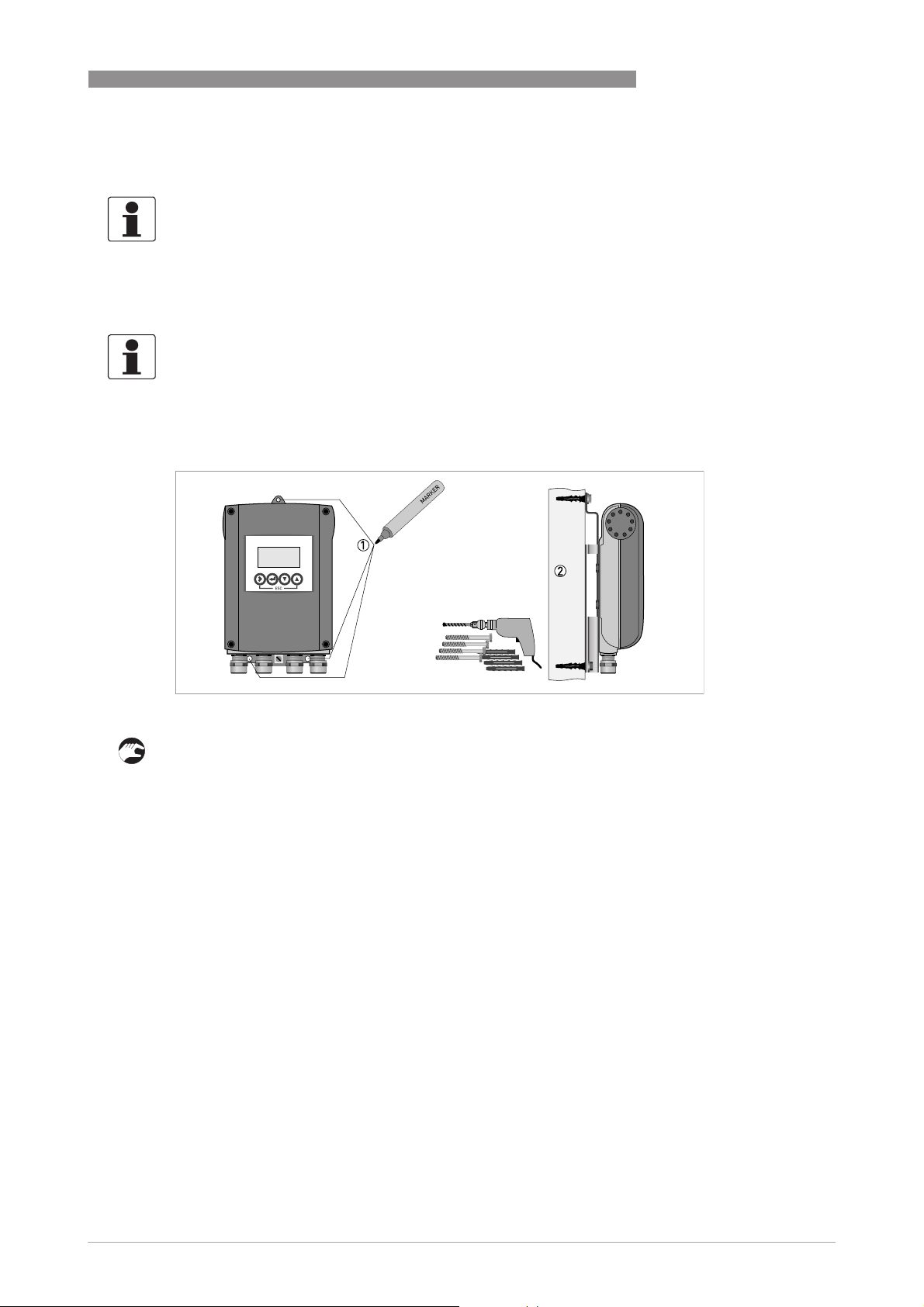
3.6.1 Wall mounting
1 Prepare the holes with the aid of the mounting plate. For further information refer to
Mounting
plate, wall-mounted version
on page 97.
2 Fasten the device securely to the wall with the mounting plate.
INFORMATION!
The signal converter is mounted directly on the measuring sensor. For installation of the
flowmeter, please observe the instructions in the supplied product documentation for the
measuring sensor.
INFORMATION!
Assembly materials and tools are not part of the delivery. Use the assembly materials and tools
in compliance with the applicable occupational health and safety directives.
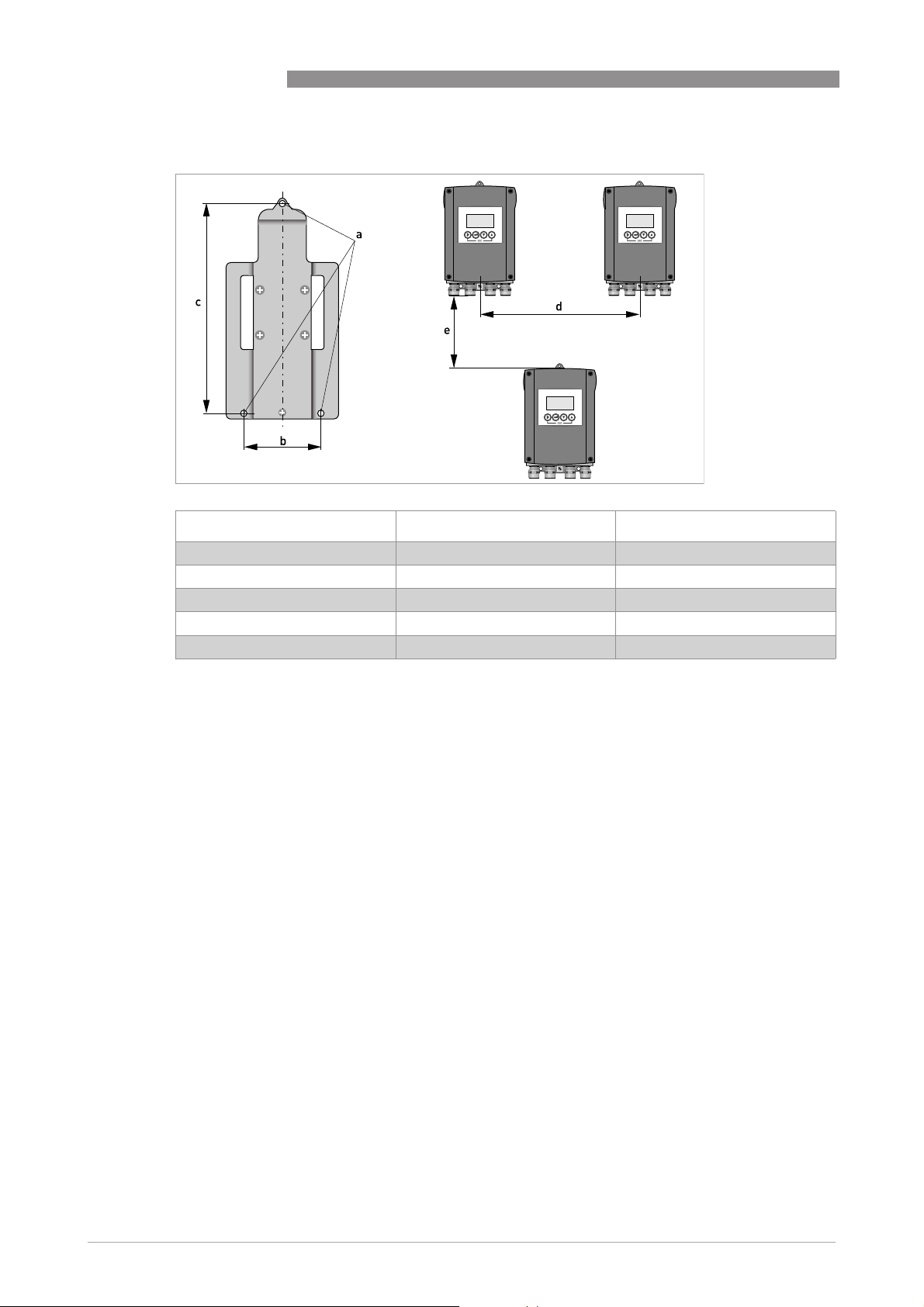
Figure 3-1: Mounting the wall-mounted housing
3 INSTALLATION
16
IFC 100
www.krohne.com 07/2014 - 4000041005 - MA IFC 100 R05 en
Mounting multiple devices next to each other
[mm] [inch]
a Ø6.5 Ø0.26
b 87.2 3.4
c 241 9.5
d 310 12.2
e 257 10.1
ELECTRICAL CONNECTIONS 4
17
IFC 100
www.krohne.com07/2014 - 4000041005 - MA IFC 100 R05 en
4.1 Safety instructions
4.2 Important notes on electrical connection
DANGER!
All work on the electrical connections may only be carried out with the power disconnected. Take
note of the voltage data on the nameplate!
DANGER!
Observe the national regulations for electrical installations!
DANGER!
For devices used in hazardous areas, additional safety notes apply; please refer to the Ex
documentation.
WARNING!
Observe without fail the local occupational health and safety regulations. Any work done on the
electrical components of the measuring device may only be carried out by properly trained
specialists.
INFORMATION!
Look at the device nameplate to ensure that the device is delivered according to your order.
Check for the correct supply voltage printed on the nameplate.
DANGER!
Electrical connection is carried out in conformity with the VDE 0100 directive "Regulations for
electrical power installations with line voltages up to 1000 V" or equivalent national regulations.
CAUTION!
•
Use suitable cable entries for the various electrical cables.
•
The measuring sensor and signal converter have been configured together at the factory. For
this reason, please connect the devices in pairs. Ensure that the measuring sensor constant
GK/GKL (see nameplates) are identically set.
•
If delivered separately or when installing devices that were not configured together, set the
signal converter to the DN size and GK/GKL of the measuring sensor, refer to Function tables
on page 56
.
4 ELECTRICAL CONNECTIONS
18
IFC 100
www.krohne.com 07/2014 - 4000041005 - MA IFC 100 R05 en
4.3 Electrical cables for remote device versions, notes
4.3.1 Notes on signal cable A
Observe the following notes:
• Lay the signal cable with fastening elements.
• It is permissible to lay the signal cable in water or in the ground.
• The insulating material is flame-retardant to EN 50265-2-1: 1997 and IEC 60322-1-2: 2005.
• The signal cable does not contain any halogens and is unplasticized, and remains flexible at
low temperatures.
• The connection of the inner shield (10) is carried out via the stranded drain wire (1).
• The connection of the outer shield (60) is carried out via the stranded drain wire (6).
4.3.2 Notes on field current cable C
INFORMATION!
Signal cable A (type DS 300) with double shield ensures proper transmission of measured
values.
DANGER!
A shielded 2-wire copper cable is used for the field current cable. The shielding MUST
MUSTMUST
MUST be
connected in the housing of the measuring sensor and signal converter.
INFORMATION!
The field current cable is not part of the scope of delivery.

ELECTRICAL CONNECTIONS 4
19
IFC 100
www.krohne.com07/2014 - 4000041005 - MA IFC 100 R05 en
4.3.3 Requirements for signal cables provided by the customer
Electrical safety
• To EN 60811 (Low Voltage Directive) or equivalent national regulations.
Capacitance of the insulated conductors
• Insulated conductor / insulated conductor < 50 pF/m
• Insulated conductor / shield < 150 pF/m
Insulation resistance
• R
iso
> 100 GΩ xkm
• U
max
< 24 V
• I
max
< 100 mA
Test voltages
• Insulated conductor / inner shield 500 V
• Insulated conductor / insulated conductor 1000 V
• Insulated conductor / outer shield 1000 V
Twisting of the insulated conductors
• At least 10 twists per meter, important for screening magnetic fields.
INFORMATION!
If the signal cable was not ordered, it is to be provided by the customer. The following
requirements regarding the electrical values of the signal cable must be observed:
4 ELECTRICAL CONNECTIONS
20
IFC 100
www.krohne.com 07/2014 - 4000041005 - MA IFC 100 R05 en
4.4 Preparing the signal and field current cables
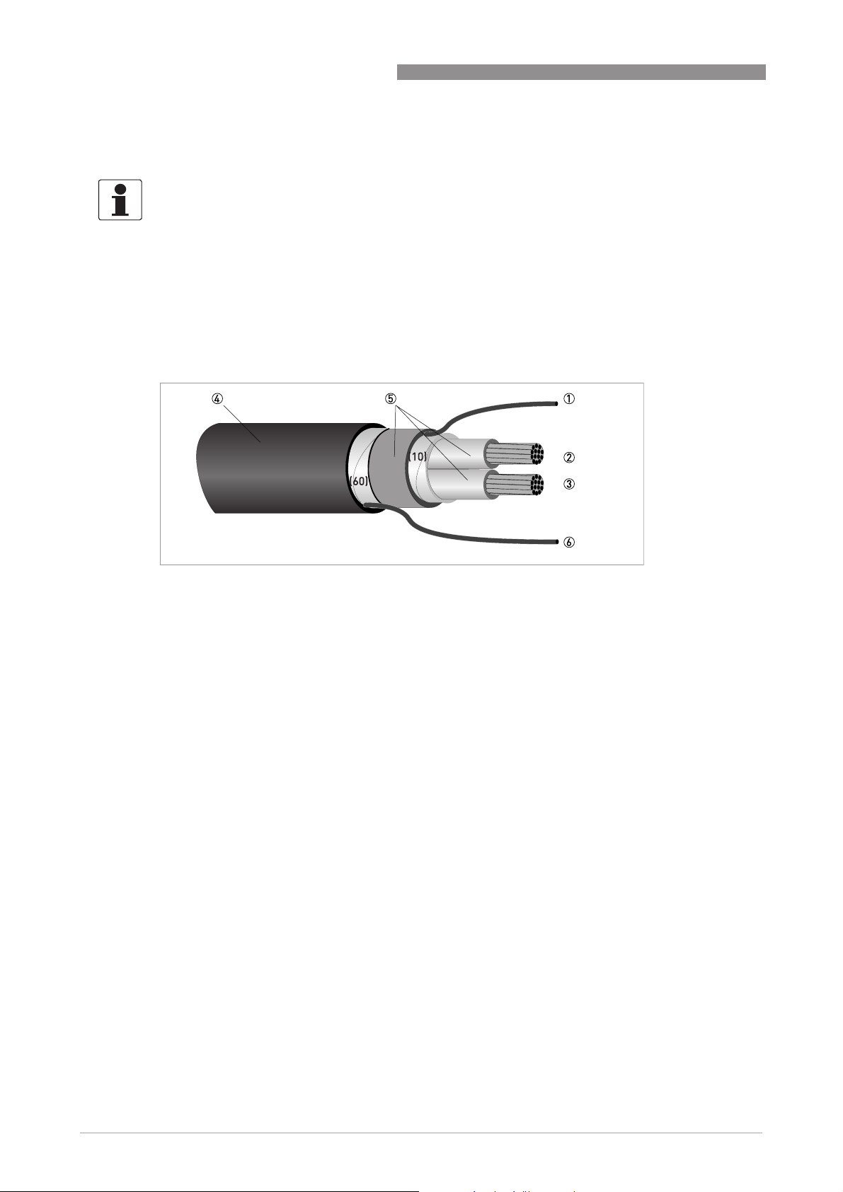
4.4.1 Signal cable A (type DS 300), construction
• Signal cable A is a double-shielded cable for signal transmission between the measuring
sensor and signal converter.
• Bending radius: ≥ 50 mm / 2"
INFORMATION!
Assembly materials and tools are not part of the delivery. Use the assembly materials and tools
in compliance with the applicable occupational health and safety directives.
Figure 4-1: Construction of signal cable A
1 Stranded drain wire (1) for the inner shield (10), 1.0 mm
2
Cu / AWG 17 (not insulated, bare)
2 Insulated wire (2), 0.5 mm
2
Cu / AWG 20
3 Insulated wire (3), 0.5 mm
2
Cu / AWG 20
4 Outer sheath
5 Insulation layers
6 Stranded drain wire (6) for the outer shield (60)
ELECTRICAL CONNECTIONS 4
21
IFC 100
www.krohne.com07/2014 - 4000041005 - MA IFC 100 R05 en
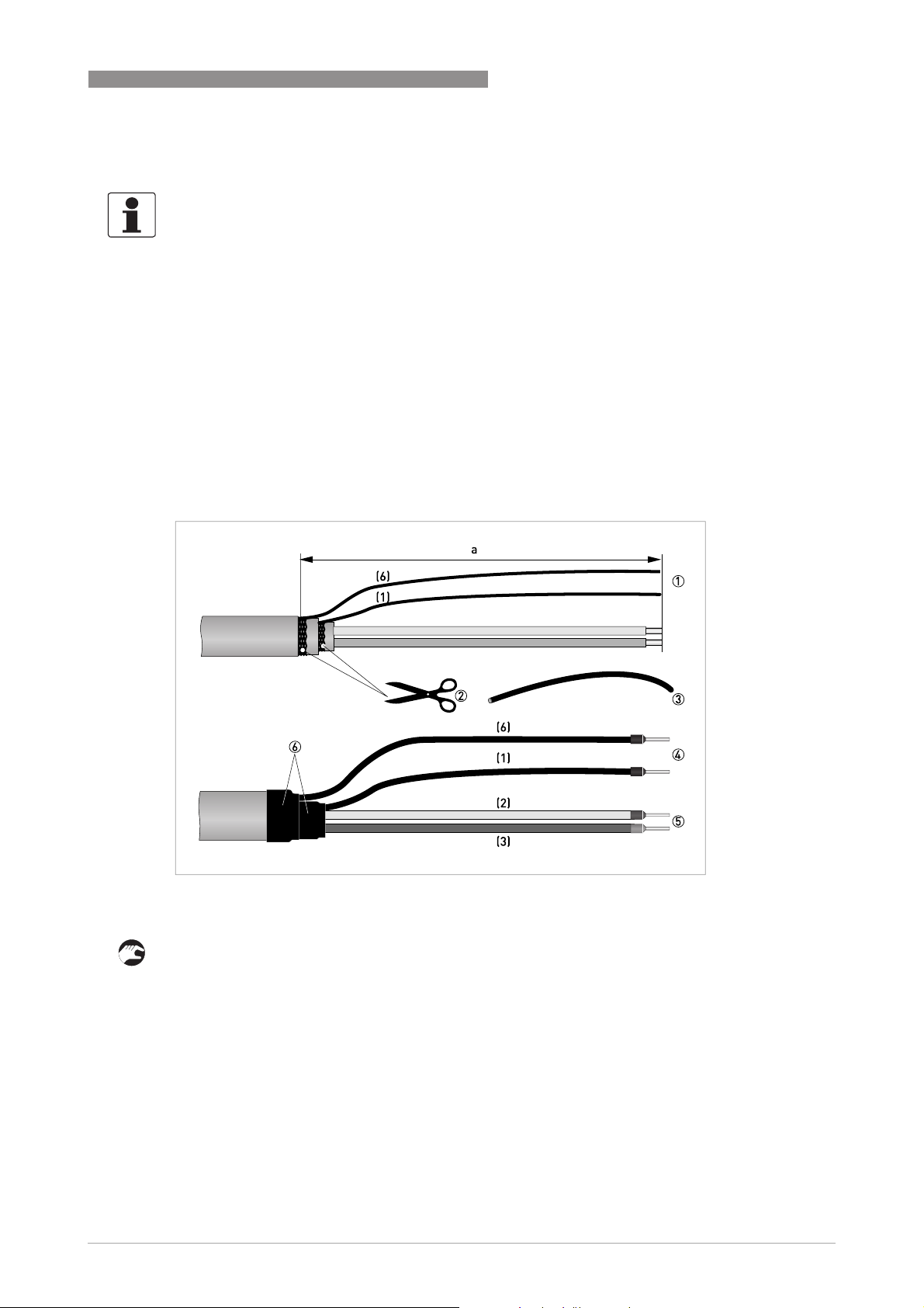
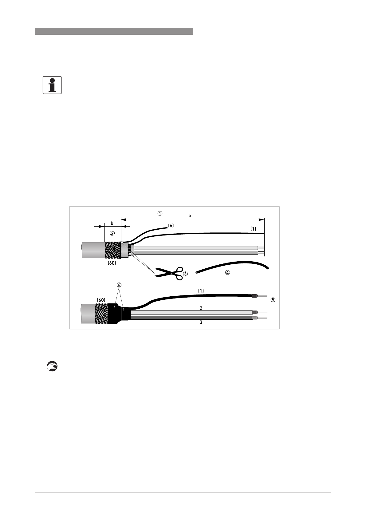
4.4.2 Preparing signal cable A, connection to signal converter
• Connection of the two shields in the signal converter is carried out via the stranded drain
wires.
• Bending radius: ≥ 50 mm / 2"
Required materials
• PVC insulating tube, Ø2.5 mm / 0.1"
• Heat-shrinkable tubing
• 2 wire end ferrules to DIN 46 228: E 1.5-8 for the stranded drain wires (1, 6)
• 2 wire end ferrules to DIN 46 228: E 0.5-8 for the insulated conductors (2, 3)
1 Strip the conductor to dimension a.
2 Cut off the inner shield (10) and the outer shield (60). Make sure not to damage the stranded
drain wires (1, 6).
3 Slide the insulating tubes over the stranded drain wires (1, 6).
4 Crimp the wire end ferrules onto the stranded drain wire.
5 Crimp the wire end ferrules onto the conductors (2, 3).
6 Pull the heat-shrinkable tubing over the prepared signal cable.
INFORMATION!
Assembly materials and tools are not part of the delivery. Use the assembly materials and tools
in compliance with the applicable occupational health and safety directives.
Figure 4-2: Preparation of signal cable A
a = 80 mm / 3.15"
4 ELECTRICAL CONNECTIONS
22
IFC 100
www.krohne.com 07/2014 - 4000041005 - MA IFC 100 R05 en
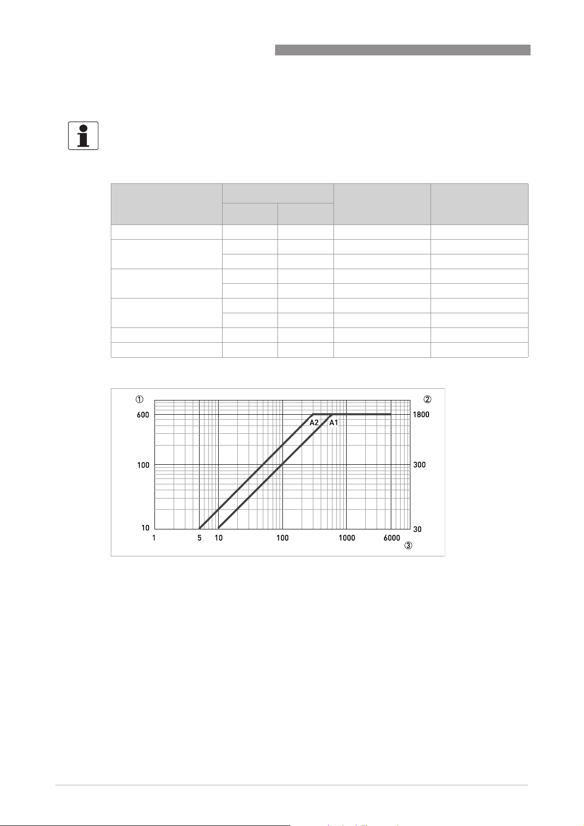
4.4.3 Length of signal cable A
INFORMATION!
For temperatures of the medium above 150
°
C / 300
°
F, a special signal cable and a ZD
intermediate socket are necessary. These are available including the changed electrical
connection diagrams.
Measuring sensor Nominal diameter Min. electrical
conductivity
[µS/cm]
Curve for signal
cable A
DN [mm] [inch]
OPTIFLUX 1000 F 10...150 3/8...6 5 A1
OPTIFLUX 2000 F 25...150 1...6 20 A1
200...1200 8...48 20 A2
OPTIFLUX 4000 F 2.5...150 1/10...6 5 A1
200...1200 8...48 5 A2
OPTIFLUX 5000 F 2.5...100 1/10...4 5 A1
150...250 6...10 5 A2
OPTIFLUX 6000 F 2.5...150 1/10...6 5 A1
WATERFLUX 3000 F 25...600 1...24 20 A1
Figure 4-3: Maximum length of signal cable A
1 Maximum length of signal cable A between the measuring sensor and signal converter [m]
2 Maximum length of signal cable A between the measuring sensor and signal converter [ft]
3 Electrical conductivity of the medium being measured [μS/cm]
ELECTRICAL CONNECTIONS 4
23
IFC 100
www.krohne.com07/2014 - 4000041005 - MA IFC 100 R05 en
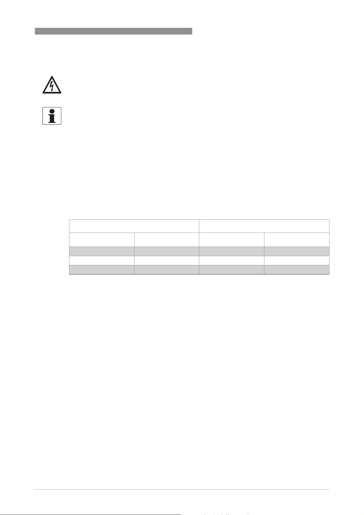
4.4.4 Preparing field current cable C, connection to signal converter
• Field current cable C is not part of the scope of delivery.
• Bending radius: ≥ 50 mm / 2"
Required materials:
• Shielded, at least 2-wire copper cable with suitable heat-shrinkable tubing
• Insulating tube, size according to the cable being used
• Wire end ferrules to DIN 46 228: size according to the cable being used
Length and cross-section of field current cable C
DANGER!
A shielded 2-wire copper cable is used as the field current cable. The shielding MUST
MUSTMUST
MUST be
connected in the housing of the measuring sensor and signal converter.
INFORMATION!
Assembly materials and tools are not part of the delivery. Use the assembly materials and tools
in compliance with the applicable occupational health and safety directives.
Length Cross-section A
F
(Cu)
[m] [ft]
[mm
2
]
[AWG]
0...150 0...492 2 x 0.75 Cu 1 2 x 18
150...300 492...984 2 x 1.5 Cu 1 2 x 14
300...600 984...1968 2 x 2.5 Cu 1 2 x 12
1 Cu = copper cross-section
4 ELECTRICAL CONNECTIONS
24
IFC 100
www.krohne.com 07/2014 - 4000041005 - MA IFC 100 R05 en
1 Strip the conductor to dimension a.
2 If a stranded drain wire is present, remove the shield that is present. Make sure not to damage
the stranded drain wire.
3 Slide an insulating tube over the stranded drain wire.
4 Crimp a wire end ferrule onto the stranded drain wire.
5 Crimp the wire end ferrules on the conductors.
6 Pull a shrinkable tube over the prepared cable.
Figure 4-4: Field current cable C, preparation for the signal converter
a = 80 mm / 3.15"
ELECTRICAL CONNECTIONS 4
25
IFC 100
www.krohne.com07/2014 - 4000041005 - MA IFC 100 R05 en
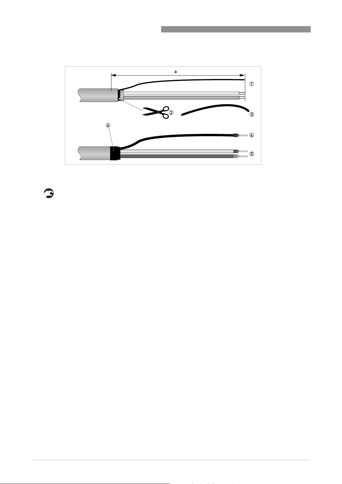
4.4.5 Preparing signal cable A, connection to measuring sensor
• The outer shield (60) is connected in the terminal compartment of the measuring sensor
directly via the shield and a clip.
• Bending radius: ≥ 50 mm / 2"
Required materials
• PVC insulating tube, Ø2.0...2.5 mm / 0.08...0.1"
• Heat-shrinkable tubing
• Wire end ferrule to DIN 46 228: E 1.5-8 for the stranded drain wire (1)
• 2 wire end ferrules to DIN 46 228: E 0.5-8 for the insulated conductors (2, 3)
1 Strip the conductor to dimension a.
2 Trim the outer shield (60) to dimension b and pull it over the outer sheath.
3 Remove the stranded drain wire (6) of the outer shield and the inner shield. Make sure not to
damage the stranded drain wire (1) of the inner shield.
4 Slide an insulating tube over the stranded drain wire (1).
5 Crimp the wire end ferrules onto conductors 2 and 3 and the stranded drain wire (1).
6 Pull the heat-shrinkable tubing over the prepared signal cable.
INFORMATION!
Assembly materials and tools are not part of the delivery. Use the assembly materials and tools
in compliance with the applicable occupational health and safety directives.
Figure 4-5: Preparing signal cable A, connection to measuring sensor
a = 50 mm / 2"
b = 10 mm / 0.39"
4 ELECTRICAL CONNECTIONS
26
IFC 100
www.krohne.com 07/2014 - 4000041005 - MA IFC 100 R05 en
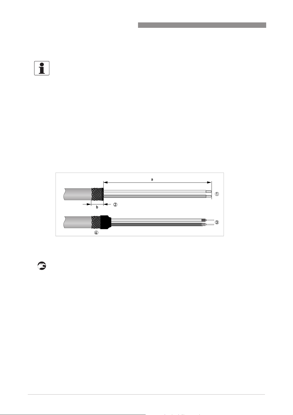
4.4.6 Preparing field current cable C, connection to measuring sensor
• The field current cable is not included in delivery.
• The shield is connected in the terminal compartment of the measuring sensor directly via the
shield and a clip.
• Bending radius: ≥ 50 mm / 2"
Required materials
• Shielded 2-wire insulated copper cable
• Insulating tube, size according to the cable being used
• Heat-shrinkable tubing
• Wire end ferrules to DIN 46 228: size according to the cable being used
1 Strip the conductor to dimension a.
2 Trim the outer shield to dimension b and pull it over the outer sheath.
3 Crimp wire end ferrules onto both conductors.
4 Pull a shrinkable tube over the prepared cable.
INFORMATION!
Assembly materials and tools are not part of the delivery. Use the assembly materials and tools
in compliance with the applicable occupational health and safety directives.
Figure 4-6: Preparation of field current cable C
a = 50 mm / 2"
b = 10 mm / 0.4"
ELECTRICAL CONNECTIONS 4
27
IFC 100
www.krohne.com07/2014 - 4000041005 - MA IFC 100 R05 en
4.5 Connecting the signal and field current cables
DANGER!
Cables may only be connected when the power is switched off.
DANGER!
The device must be grounded in accordance with regulations in order to protect personnel
against electric shocks.
DANGER!
For devices used in hazardous areas, additional safety notes apply; please refer to the Ex
documentation.
WARNING!
Observe without fail the local occupational health and safety regulations. Any work done on the
electrical components of the measuring device may only be carried out by properly trained
specialists.
4 ELECTRICAL CONNECTIONS
28
IFC 100
www.krohne.com 07/2014 - 4000041005 - MA IFC 100 R05 en
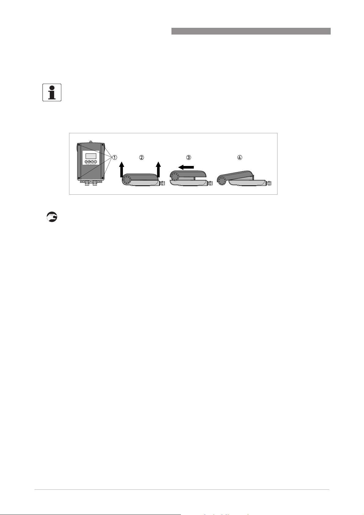
4.5.1 Connecting the signal and field current cables to the signal converter, remote
version
Open housing
1 Loosen the 4 screws with a suitable tool.
2 Lift the housing at the top and bottom at the same time.
3 Slide the housing cover upward.
4 The housing cover is guided and held by the inside hinge.
INFORMATION!
The compact version is supplied preassembled from the factory.
Figure 4-7: Open housing
ELECTRICAL CONNECTIONS 4
29
IFC 100
www.krohne.com07/2014 - 4000041005 - MA IFC 100 R05 en
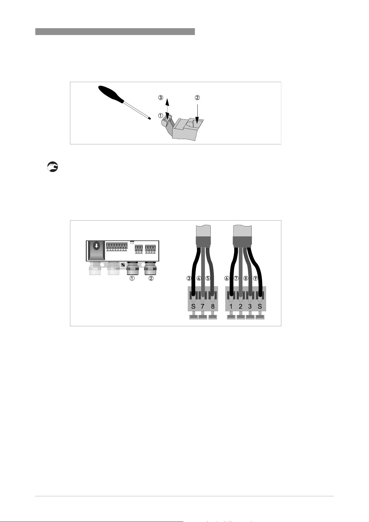
Connecting the signal and field current cables
Connect the electrical conductors as follows:
1 Push the lever downwards with a screwdriver in good condition (blade: 3.5 mm wide and
0.5 mm thick).
2 Insert the electrical conductor into the plug.
3 The conductor will be clamped as soon as the lever is released.
Figure 4-8: Function of the electrical connection terminal
Figure 4-9: Connecting the signal and field current cables
1 Cable entry for field current cable
2 Cable entry for signal cable
3 Connecting the field current cable shield
4 Electrical conductor (7)
5 Electrical conductor (8)
6 Stranded drain wire (1) of the inner shield (10) of the signal cable
7 Electrical conductor (2)
8 Electrical conductor (3)
9 Stranded drain wire (S) of the outer shield (60)
4 ELECTRICAL CONNECTIONS
30
IFC 100
www.krohne.com 07/2014 - 4000041005 - MA IFC 100 R05 en
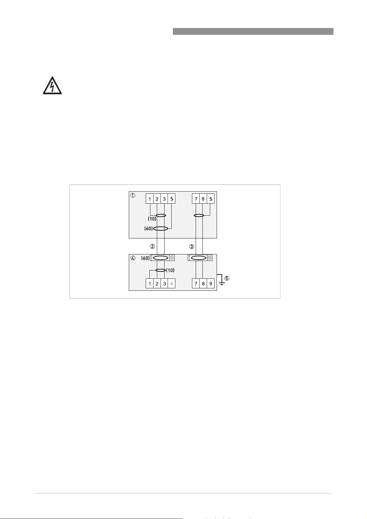
4.5.2 Connection diagram for signal and field current cable
• A shielded 2-wire copper cable is used as the field current cable. The shielding MUST
MUSTMUST
MUST be
connected in the housing of the measuring sensor and signal converter.
• The outer shield (60) is connected in the terminal compartment of the measuring sensor
directly via the shield and a clip.
• Bending radius of signal and field current cable: ≥ 50 mm / 2"
• The following illustration is schematic. The positions of the electrical connection terminals
may vary depending on the housing version.
DANGER!
The device must be grounded in accordance with regulations in order to protect personnel
against electric shocks.
Figure 4-10: Connection diagram for signal and field current cable
1 Electrical terminal compartment in signal converter
2 Signal cable A
3 Field current cable C
4 Electrical terminal compartment in measuring sensor
5 Functional ground FE
 Loading...