


Jvc KD-DV7206-UT, KD-DV7206-UN, KD-DV7206-U, KD-DV7206-A, KD-DV7205-UT Service Manual
...SERVICE MANUAL
DVD/CD RECEIVER
KD-ADV6270J,KD-DV6200J,KD-DV6201E, KD-DV6201EU,KD-DV6202E,KD-DV6202EU, KD-DV7205U,KD-DV7205UN,KD-DV7205UT, KD-DV7205A,KD-DV7206U,KD-DV7206UN, KD-DV7206UT,KD-DV7206A,KD-DV6207EE
Lead free solder used in the board (material : Sn-Ag-Cu, melting point : 219 Centigrade)
TABLE OF CONTENTS
1 PRECAUTIONS . . . . . . . . . . . . . . . . . . . . . . . . . . . . . . . . . . . . . . . . . . . . . . . . . . . . . . . . . . . . . . . . . . . . . . . 1-6 2 SPECIFIC SERVICE INSTRUCTIONS . . . . . . . . . . . . . . . . . . . . . . . . . . . . . . . . . . . . . . . . . . . . . . . . . . . . . . 1-9 3 DISASSEMBLY . . . . . . . . . . . . . . . . . . . . . . . . . . . . . . . . . . . . . . . . . . . . . . . . . . . . . . . . . . . . . . . . . . . . . . 1-10 4 ADJUSTMENT . . . . . . . . . . . . . . . . . . . . . . . . . . . . . . . . . . . . . . . . . . . . . . . . . . . . . . . . . . . . . . . . . . . . . . . 1-24 5 TROUBLESHOOTING . . . . . . . . . . . . . . . . . . . . . . . . . . . . . . . . . . . . . . . . . . . . . . . . . . . . . . . . . . . . . . . . . 1-31
COPYRIGHT © 2006 Victor Company of Japan, Limited
No.MA250
2006/3
SPECIFICATION
KD-ADV6270/KD-DV6200
|
|
|
AUDIO AMPLIFIER SECTION |
|
|
|||||
Power Output |
|
20 W RMS × 4 Channels at 4 Ω |
and [< or =] 1% THD+N |
|||||||
Signal to Noise Ratio |
|
80 dBA (reference: 1 W into 4 Ω |
) |
|
|
|||||
Load Impedance |
|
4 Ω (4 Ω to 8 Ω allowance) |
|
|
|
|||||
Equalizer Control Range |
|
Frequencies |
60 Hz, 150 Hz, 400 Hz, 1 kHz, 2.4 kHz, 6 kHz, 15 kHz |
|||||||
|
|
Level |
±10 dB |
|
|
|
|
|
|
|
Audio Output Level |
|
Digital (DIGITAL OUT: Optical) |
Signal wave length : 660 nm |
|
|
|
||||
|
|
|
Output level : -21 dBm to -15 dBm |
|
|
|||||
|
|
Line-Out Level/Impedance |
KD-ADV6270 : 5.0 V/20 kΩ |
load (full scale) |
|
|||||
|
|
|
KD-DV6200 : 2.5 V/20 kΩ |
load (full scale) |
|
|||||
|
|
Output Impedance |
1 kΩ |
|
|
|
|
|
|
|
Subwoofer-out Level/Impedance |
KD-ADV6270 : 2.5 V/20 kΩ |
load (full scale) |
|
|||||||
|
|
|
KD-DV6200 : 2.0 V/20 kΩ |
load (full scale) |
|
|||||
Color system |
|
NTSC |
|
|
|
|
|
|
|
|
Video Output (composite) |
|
1 Vp-p/75 Ω |
|
|
|
|
|
|||
Other Terminals |
|
LINE IN, CD changer, 2nd AUDIO OUT |
|
|||||||
|
|
|
|
TUNER SECTION |
|
|
|
|||
Frequency Range |
|
FM |
87.5 MHz to 107.9 MHz (with channel interval set to 100 kHz or 200 kHz) |
|||||||
|
|
|
87.5 MHz to 108.0 MHz (with channel interval set to 50 kHz) |
|||||||
|
|
AM |
530 kHz to 1 710 kHz (with channel interval set to 10 kHz) |
|||||||
|
|
|
531 kHz to 1 602 kHz (with channel interval set to 9 kHz) |
|||||||
FM Tuner |
|
Usable Sensitivity |
11.3 dBf (1.0 µV/75 Ω ) |
|
|
|
|
|||
|
|
50 dB Quieting Sensitivity |
16.3 dBf (1.8 µV/75 Ω ) |
|
|
|
|
|||
|
|
Alternate Channel Selectivity (400 kHz) |
65 dB |
|
|
|
|
|
|
|
|
|
Frequency Response |
40 Hz to 15 000 Hz |
|
|
|
|
|
||
|
|
Stereo Separation |
35 dB |
|
|
|
|
|
|
|
AM Tuner |
|
Sensitivity/Selectivity |
20 µV/35 dB |
|
|
|
|
|
||
|
|
|
DVD/CD PLAYER SECTION |
|
|
|
||||
Signal Detection System |
|
Non-contact optical pickup (semiconductor laser) |
||||||||
Number of Channels |
|
2 channels (stereo) |
|
|
|
|
|
|||
Frequency Response |
|
DVD, fs=48 kHz |
16 Hz to 22 000 Hz |
|
|
|
|
|
||
|
|
DVD, fs=96 kHz |
16 Hz to 22 000 Hz |
|
|
|
|
|
||
|
|
CD, fs=44.1 kHz |
16 Hz to 20 000 Hz |
|
|
|
|
|
||
Dynamic Range |
|
|
96 dB |
|
|
|
|
|
|
|
Signal-to-Noise Ratio |
|
98 dB |
|
|
|
|
|
|
|
|
Wow and Flutter |
|
Less than measurable limit |
|
|
|
|||||
DivX |
|
Video : Max. Resolution |
720 × |
480 pixels (30 fps) |
|
|
|
|
||
|
|
|
720 × |
576 pixels (25 fps) |
|
|
|
|
||
|
|
Audio |
Bit Rate : 32 kbps - 320 kbps |
|
|
|
||||
|
|
Sampling Frequency |
MPEG-1 : 32 kHz, 44.1 kHz, 48 kHz |
|
|
|||||
|
|
|
MPEG-2 : 16 kHz, 22.05 kHz, 24 kHz |
|
|
|||||
MPEG Video |
|
Video : Max. Resolution |
720 × |
480 pixels (30 fps) |
|
|
|
|
||
|
|
|
720 × |
576 pixels (25 fps) |
|
|
|
|
||
|
|
Audio |
Bit Rate : 32 kbps - 384 kbps |
|
|
|
||||
|
|
Sampling Frequency |
32 kHz, 44.1 kHz, 48 kHz |
|
|
|
|
|||
MP3 |
|
Bit Rate |
32 kbps - 320 kbps |
|
|
|
|
|
||
|
|
Sampling Frequency |
MPEG-1 : 32 kHz, 44.1 kHz, 48 kHz |
|
|
|||||
|
|
|
MPEG-2 : 16 kHz, 22.05 kHz, 24 kHz |
|
|
|||||
WMA |
|
Bit Rate |
32 kbps - 320 kbps |
|
|
|
|
|
||
|
|
Sampling Frequency |
22.05 kHz, 32 kHz, 44.1 kHz, 48 kHz |
|
|
|||||
WAV |
|
Quantization Bit Rate |
16 bit |
|
|
|
|
|
|
|
|
|
Sampling Frequency |
44.1 kHz |
|
|
|
|
|
|
|
|
|
|
|
|
USB MEMORY |
|
|
|
|
|
Format |
|
FAT 12/16/32 |
|
|
|
|
|
|||
Storage |
|
Less than 4 GB (1 partition type) |
|
|
||||||
Playable Audio Format |
|
MP3/WMA |
|
|
|
|
|
|||
Max. Current |
|
Less than 500 mA |
|
|
|
|
|
|||
MP3 |
|
Bit Rate |
32 kbps - 320 kbps |
|
|
|
|
|
||
|
|
Sampling Frequency |
MPEG-1 : 48 kHz, 44.1 kHz, 32 kHz |
|
|
|||||
|
|
|
MPEG-2 : 24 kHz, 22.05 kHz, 16 kHz |
|
|
|||||
|
|
|
MPEG-2.5 : 12 kHz, 11.025 kHz, 8 kHz |
|
||||||
WMA |
|
Bit Rate |
5 kbps - 320 kbps |
|
|
|
|
|
||
|
|
Sampling Frequency |
8 kHz - 48 kHz |
|
|
|
|
|
||
|
|
|
|
|
GENERAL |
|
|
|
|
|
Power Requirement |
|
Operating Voltage |
DC 14.4 V (11 V to 16 V allowance) |
|
|
|||||
Grounding System |
|
|
Negative ground |
|
|
|
|
|
||
Allowable Operating Temperature |
0°C to +40°C (32°F to 104°F) |
|
|
|
||||||
Dimensions (W × H × D) |
|
Installation Size (approx.) |
182 mm × |
52 mm × |
158 mm (7-3/16" × |
2-1/16" × |
6-1/4") |
|||
|
|
Panel Size (approx.) |
188 mm × |
58 mm × |
11 mm (7-7/16" × |
2-5/16" × |
7/16") |
|||
Mass (approx.) |
|
|
1.7 kg (3.3 lbs) (excluding accessories) |
|
||||||
1-2 (No.MA250)
KD-DV6201/KD-DV6202
|
AUDIO AMPLIFIER SECTION |
||||
Maximum Power Output |
Front/Rear |
50 W per channel |
|
||
Continuous Power Output (RMS) |
Front/Rear |
19 W per channel into 4 Ω , 40 Hz to 20 000 Hz at no more than 0.8% total harmonic distortion |
|||
Load Impedance |
|
4 Ω (4 Ω to 8 Ω allowance) |
|||
Equalizer Control Range |
Frequencies |
60 Hz, 150 Hz, 400 Hz, 1 kHz, 2.4 kHz, 6 kHz, 15 kHz |
|||
|
Level |
±10 dB |
|
|
|
Signal to Noise Ratio |
|
70 dB |
|
|
|
Audio Output Level |
Digital (DIGITAL OUT: Optical) |
Signal wave length : 660 nm |
|||
|
|
Output level : -21 dBm to -15 dBm |
|||
|
Line-Out Level/Impedance |
2.5 V/20 kΩ load (full scale) |
|||
|
Output Impedance |
1 kΩ |
|
|
|
Subwoofer-out Level/Impedance |
|
2.0 V/20 kΩ load (full scale) |
|||
Color system |
|
PAL |
|
|
|
Video Output (composite) |
|
1 Vp-p/75 Ω |
|
||
Other Terminals |
|
LINE IN, CD changer, 2nd AUDIO OUT |
|||
|
|
TUNER SECTION |
|
||
Frequency Range |
FM |
87.5 MHz to 108.0 MHz |
|||
|
AM |
(MW) 522 kHz to 1 620 kHz |
|||
|
|
(LW) 144 kHz to 279 kHz |
|||
FM Tuner |
Usable Sensitivity |
11.3 dBf (1.0 µV/75 Ω ) |
|||
|
50 dB Quieting Sensitivity |
16.3 dBf (1.8 µV/75 Ω ) |
|||
|
Alternate Channel Selectivity (400 kHz) |
65 dB |
|
|
|
|
Frequency Response |
40 Hz to 15 000 Hz |
|
||
|
Stereo Separation |
30 dB |
|
|
|
MW Tuner |
Sensitivity/Selectivity |
20 µV/35 dB |
|
||
LW Tuner |
Sensitivity |
50 µV |
|
|
|
|
DVD/CD PLAYER SECTION |
||||
Signal Detection System |
|
Non-contact optical pickup (semiconductor laser) |
|||
Number of Channels |
|
2 channels (stereo) |
|
||
Frequency Response |
DVD, fs=48 kHz |
16 Hz to 22 000 Hz |
|
||
|
DVD, fs=96 kHz |
16 Hz to 22 000 Hz |
|
||
|
CD, fs=44.1 kHz |
16 Hz to 20 000 Hz |
|
||
Dynamic Range |
|
96 dB |
|
|
|
Signal-to-Noise Ratio |
|
98 dB |
|
|
|
Wow and Flutter |
|
Less than measurable limit |
|||
DivX |
Video : Max. Resolution |
720 × |
480 pixels (30 fps) |
||
|
|
720 × |
576 pixels (25 fps) |
||
|
Audio |
Bit Rate : 32 kbps - 320 kbps |
|||
|
Sampling Frequency |
MPEG-1 : 32 kHz, 44.1 kHz, 48 kHz |
|||
|
|
MPEG-2 : 16 kHz, 22.05 kHz, 24 kHz |
|||
MPEG Video |
Video : Max. Resolution |
720 × |
480 pixels (30 fps) |
||
|
|
720 × |
576 pixels (25 fps) |
||
|
Audio |
Bit Rate : 32 kbps - 384 kbps |
|||
|
|
Sampling Frequency : 32 kHz, 44.1 kHz, 48 kHz |
|||
MP3 |
Bit Rate |
32 kbps - 320 kbps |
|
||
|
Sampling Frequency |
MPEG-1 : 32 kHz, 44.1 kHz, 48 kHz |
|||
|
|
MPEG-2 : 16 kHz, 22.05 kHz, 24 kHz |
|||
WMA |
Bit Rate |
32 kbps - 320 kbps |
|
||
|
Sampling Frequency |
22.05 kHz, 32 kHz, 44.1 kHz, 48 kHz |
|||
WAV |
Quantization Bit Rate |
16 bit |
|
|
|
|
Sampling Frequency |
44.1 kHz |
|
|
|
|
|
USB MEMORY |
|
||
Format |
|
FAT 12/16/32 |
|
||
Storage |
|
Less than 4 GB (1 partition type) |
|||
Playable Audio Format |
|
MP3/WMA |
|
||
Max. Current |
|
Less than 500 mA |
|
||
MP3 |
Bit Rate |
32 kbps - 320 kbps |
|
||
|
Sampling Frequency |
MPEG-1 : 48 kHz, 44.1 kHz, 32 kHz |
|||
|
|
MPEG-2 : 24 kHz, 22.05 kHz, 16 kHz |
|||
|
|
MPEG-2.5 : 12 kHz, 11.025 kHz, 8 kHz |
|||
WMA |
Bit Rate |
5 kbps - 320 kbps |
|
||
|
Sampling Frequency |
8 kHz - 48 kHz |
|
||
|
|
GENERAL |
|
||
Power Requirement |
Operating Voltage |
DC 14.4 V (11 V to 16 V allowance) |
|||
Grounding System |
|
Negative ground |
|
||
Allowable Operating Temperature |
|
0°C to +40°C |
|
||
Dimensions (W × H × D) |
Installation Size (approx.) |
182 mm × |
52 mm × |
158 mm |
|
|
Panel Size (approx.) |
188 mm × |
58 mm × |
11 mm |
|
Mass (approx.) |
|
1.7 kg (excluding accessories) |
|||
(No.MA250)1-3
KD-DV7205/KD-DV7206
|
AUDIO AMPLIFIER SECTION |
||||
Maximum Power Output |
Front/Rear |
50 W per channel |
|
||
Continuous Power Output (RMS) |
Front/Rear |
19 W per channel into 4 Ω , 40 Hz to 20 000 Hz at no more than 0.8% total harmonic distortion |
|||
Load Impedance |
|
4 Ω (4 Ω to 8 Ω allowance) |
|||
Equalizer Control Range |
Frequencies |
60 Hz, 150 Hz, 400 Hz, 1 kHz, 2.4 kHz, 6 kHz, 15 kHz |
|||
|
Level |
±10 dB |
|
|
|
Signal to Noise Ratio |
|
70 dB |
|
|
|
Audio Output Level |
Digital (DIGITAL OUT: Optical) |
Signal wave length : 660 nm |
|||
|
|
Output level : -21 dBm to -15 dBm |
|||
|
Line-Out Level/Impedance |
2.5 V/20 kΩ load (full scale) |
|||
|
Output Impedance |
1 kΩ |
|
|
|
Subwoofer-out Level/Impedance |
|
2.0 V/20 kΩ load (full scale) |
|||
Color system |
|
PAL/NTSC |
|
||
Video Output (composite) |
|
1 Vp-p/75 Ω |
|
||
Other Terminals |
|
LINE IN, CD changer, 2nd AUDIO OUT |
|||
|
|
TUNER SECTION |
|
||
Frequency Range |
FM |
87.5 MHz to 108.0 MHz |
|||
|
AM |
531 kHz to 1 602 kHz |
|||
FM Tuner |
Usable Sensitivity |
11.3 dBf (1.0 µV/75 Ω ) |
|||
|
50 dB Quieting Sensitivity |
16.3 dBf (1.8 µV/75 Ω ) |
|||
|
Alternate Channel Selectivity (400 kHz) |
65 dB |
|
|
|
|
Frequency Response |
40 Hz to 15 000 Hz |
|
||
|
Stereo Separation |
30 dB |
|
|
|
AM Tuner |
Sensitivity/Selectivity |
20 µV/35 dB |
|
||
|
DVD/CD PLAYER SECTION |
||||
Signal Detection System |
|
Non-contact optical pickup (semiconductor laser) |
|||
Number of Channels |
|
2 channels (stereo) |
|
||
Frequency Response |
DVD, fs=48 kHz |
16 Hz to 22 000 Hz |
|
||
|
DVD, fs=96 kHz |
16 Hz to 22 000 Hz |
|
||
|
CD, fs=44.1 kHz |
16 Hz to 20 000 Hz |
|
||
Dynamic Range |
|
96 dB |
|
|
|
Signal-to-Noise Ratio |
|
98 dB |
|
|
|
Wow and Flutter |
|
Less than measurable limit |
|||
DivX |
Video : Max. Resolution |
720 × |
480 pixels (30 fps) |
||
|
|
720 × |
576 pixels (25 fps) |
||
|
Audio |
Bit Rate : 32 kbps - 320 kbps |
|||
|
Sampling Frequency |
MPEG-1 : 32 kHz, 44.1 kHz, 48 kHz |
|||
|
|
MPEG-2 : 16 kHz, 22.05 kHz, 24 kHz |
|||
MPEG Video |
Video : Max. Resolution |
720 × |
480 pixels (30 fps) |
||
|
|
720 × |
576 pixels (25 fps) |
||
|
Audio |
Bit Rate : 32 kbps - 384 kbps |
|||
|
|
Sampling Frequency : 32 kHz, 44.1 kHz, 48 kHz |
|||
MP3 |
Bit Rate |
32 kbps - 320 kbps |
|
||
|
Sampling Frequency |
MPEG-1 : 32 kHz, 44.1 kHz, 48 kHz |
|||
|
|
MPEG-2 : 16 kHz, 22.05 kHz, 24 kHz |
|||
WMA |
Bit Rate |
32 kbps - 320 kbps |
|
||
|
Sampling Frequency |
22.05 kHz, 32 kHz, 44.1 kHz, 48 kHz |
|||
WAV |
Quantization Bit Rate |
16 bit |
|
|
|
|
Sampling Frequency |
44.1 kHz |
|
|
|
|
|
USB MEMORY |
|
||
Format |
|
FAT 12/16/32 |
|
||
Storage |
|
Less than 4 GB (1 partition type) |
|||
Playable Audio Format |
|
MP3/WMA |
|
||
Max. Current |
|
Less than 500 mA |
|
||
MP3 |
Bit Rate |
32 kbps - 320 kbps |
|
||
|
Sampling Frequency |
MPEG-1 : 48 kHz, 44.1 kHz, 32 kHz |
|||
|
|
MPEG-2 : 24 kHz, 22.05 kHz, 16 kHz |
|||
|
|
MPEG-2.5 : 12 kHz, 11.025 kHz, 8 kHz |
|||
WMA |
Bit Rate |
5 kbps - 320 kbps |
|
||
|
Sampling Frequency |
8 kHz - 48 kHz |
|
||
|
|
GENERAL |
|
||
Power Requirement |
Operating Voltage |
DC 14.4 V (11 V to 16 V allowance) |
|||
Grounding System |
|
Negative ground |
|
||
Allowable Operating Temperature |
|
0°C to +40°C |
|
||
Dimensions (W × H × D) |
Installation Size (approx.) |
182 mm × |
52 mm × |
158 mm |
|
|
Panel Size (approx.) |
188 mm × |
58 mm × |
11 mm |
|
Mass (approx.) |
|
1.7 kg (excluding accessories) |
|||
1-4 (No.MA250)
KD-DV6207
|
AUDIO AMPLIFIER SECTION |
||||
Maximum Power Output |
Front/Rear |
50 W per channel |
|
||
Continuous Power Output (RMS) |
Front/Rear |
19 W per channel into 4 Ω , 40 Hz to 20 000 Hz at no more than 0.8% total harmonic distortion |
|||
Load Impedance |
|
4 Ω (4 Ω to 8 Ω allowance) |
|||
Equalizer Control Range |
Frequencies |
60 Hz, 150 Hz, 400 Hz, 1 kHz, 2.4 kHz, 6 kHz, 15 kHz |
|||
|
Level |
±10 dB |
|
|
|
Signal to Noise Ratio |
|
70 dB |
|
|
|
Audio Output Level |
Digital (DIGITAL OUT: Optical) |
Signal wave length : 660 nm |
|||
|
|
Output level : -21 dBm to -15 dBm |
|||
|
Line-Out Level/Impedance |
2.5 V/20 kΩ load (full scale) |
|||
|
Output Impedance |
1 kΩ |
|
|
|
Subwoofer-out Level/Impedance |
|
2.0 V/20 kΩ load (full scale) |
|||
Color system |
|
PAL |
|
|
|
Video Output (composite) |
|
1 Vp-p/75 Ω |
|
||
Other Terminals |
|
LINE IN, CD changer, 2nd AUDIO OUT |
|||
|
|
TUNER SECTION |
|
||
Frequency Range |
FM1 /FM2 |
87.5 MHz to 108.0 MHz |
|||
|
FM3 |
65.00 MHz to 74.00 MHz |
|||
|
AM |
(MW) 522 kHz to 1 620 kHz |
|||
|
|
(LW) 144 kHz to 279 kHz |
|||
FM Tuner |
Usable Sensitivity |
11.3 dBf (1.0 µV/75 Ω ) |
|||
|
50 dB Quieting Sensitivity |
16.3 dBf (1.8 µV/75 Ω ) |
|||
|
Alternate Channel Selectivity (400 kHz) |
65 dB |
|
|
|
|
Frequency Response |
40 Hz to 15 000 Hz |
|
||
|
Stereo Separation |
30 dB |
|
|
|
MW Tuner |
Sensitivity/Selectivity |
20 µV/35 dB |
|
||
LW Tuner |
Sensitivity |
50 µV |
|
|
|
|
DVD/CD PLAYER SECTION |
||||
Signal Detection System |
|
Non-contact optical pickup (semiconductor laser) |
|||
Number of Channels |
|
2 channels (stereo) |
|
||
Frequency Response |
DVD, fs=48 kHz |
16 Hz to 22 000 Hz |
|
||
|
DVD, fs=96 kHz |
16 Hz to 22 000 Hz |
|
||
|
CD, fs=44.1 kHz |
16 Hz to 20 000 Hz |
|
||
Dynamic Range |
|
96 dB |
|
|
|
Signal-to-Noise Ratio |
|
98 dB |
|
|
|
Wow and Flutter |
|
Less than measurable limit |
|||
DivX |
Video : Max. Resolution |
720 × |
480 pixels (30 fps) |
||
|
|
720 × |
576 pixels (25 fps) |
||
|
Audio |
Bit Rate : 32 kbps - 320 kbps |
|||
|
Sampling Frequency |
MPEG-1 : 32 kHz, 44.1 kHz, 48 kHz |
|||
|
|
MPEG-2 : 16 kHz, 22.05 kHz, 24 kHz |
|||
MPEG Video |
Video : Max. Resolution |
720 × |
480 pixels (30 fps) |
||
|
|
720 × |
576 pixels (25 fps) |
||
|
Audio |
Bit Rate : 32 kbps - 384 kbps |
|||
|
Sampling Frequency |
32 kHz, 44.1 kHz, 48 kHz |
|||
MP3 |
Bit Rate |
32 kbps - 320 kbps |
|
||
|
Sampling Frequency |
MPEG-1 : 32 kHz, 44.1 kHz, 48 kHz |
|||
|
|
MPEG-2 : 16 kHz, 22.05 kHz, 24 kHz |
|||
WMA |
Bit Rate |
32 kbps - 320 kbps |
|
||
|
Sampling Frequency |
22.05 kHz, 32 kHz, 44.1 kHz, 48 kHz |
|||
WAV |
Quantization Bit Rate |
16 bit |
|
|
|
|
Sampling Frequency |
44.1 kHz |
|
|
|
|
|
USB MEMORY |
|
||
Format |
|
FAT 12/16/32 |
|
||
Storage |
|
Less than 4 GB (1 partition type) |
|||
Playable Audio Format |
|
MP3/WMA |
|
||
Max. Current |
|
Less than 500 mA |
|
||
MP3 |
Bit Rate |
32 kbps - 320 kbps |
|
||
|
Sampling Frequency |
MPEG-1 : 48 kHz, 44.1 kHz, 32 kHz |
|||
|
|
MPEG-2 : 24 kHz, 22.05 kHz, 16 kHz |
|||
|
|
MPEG-2.5 : 12 kHz, 11.025 kHz, 8 kHz |
|||
WMA |
Bit Rate |
5 kbps - 320 kbps |
|
||
|
Sampling Frequency |
8 kHz - 48 kHz |
|
||
|
|
GENERAL |
|
||
Power Requirement |
Operating Voltage |
DC 14.4 V (11 V to 16 V allowance) |
|||
Grounding System |
|
Negative ground |
|
||
Allowable Operating Temperature |
|
0°C to +40°C |
|
||
Dimensions (W × H × D) |
Installation Size (approx.) |
182 mm × |
52 mm × |
158 mm |
|
|
Panel Size (approx.) |
188 mm × |
58 mm × |
11 mm |
|
Mass (approx.) |
|
1.7 kg (excluding accessories) |
|||
Design and specifications are subject to change without notice.
(No.MA250)1-5

SECTION 1
PRECAUTIONS
1.1Safety Precautions
!


 Burrs formed during molding may be left over on some parts of the chassis. Therefore,
pay attention to such burrs in the case of preforming repair of this system.
! |
Please use enough caution not to see the beam directly or touch it in case of an |
|
adjustment or operation check. |
|
|
1-6 (No.MA250)
1.2Preventing static electricity
Electrostatic discharge (ESD), which occurs when static electricity stored in the body, fabric, etc. is discharged, can destroy the laser diode in the traverse unit (optical pickup). Take care to prevent this when performing repairs.
1.2.1Grounding to prevent damage by static electricity
Static electricity in the work area can destroy the optical pickup (laser diode) in devices such as laser products. Be careful to use proper grounding in the area where repairs are being performed.
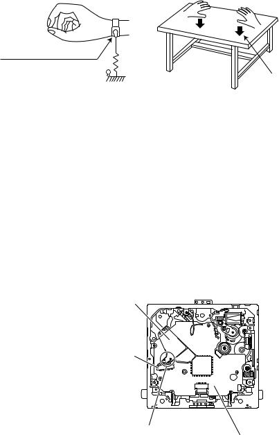
(1)Ground the workbench
Ground the workbench by laying conductive material (such as a conductive sheet) or an iron plate over it before placing the traverse unit (optical pickup) on it.
(2)Ground yourself
Use an anti-static wrist strap to release any static electricity built up in your body.
(caption)
Anti-static wrist strap
1M
Conductive material (conductive sheet) or iron plate
(3)Handling the optical pickup
•In order to maintain quality during transport and before installation, both sides of the laser diode on the replacement optical pickup are shorted. After replacement, return the shorted parts to their original condition.
(Refer to the text.)
•Do not use a tester to check the condition of the laser diode in the optical pickup. The tester's internal power source can easily destroy the laser diode.
1.3Handling the traverse unit (optical pickup)
(1)Do not subject the traverse unit (optical pickup) to strong shocks, as it is a sensitive, complex unit.
(2)Cut off the shorted part of the flexible cable using nippers, etc. after replacing the optical pickup. For specific details, refer to the replacement procedure in the text. Remove the anti-static pin when replacing the traverse unit. Be careful not to take too long a time when attaching it to the connector.
(3)Handle the flexible cable carefully as it may break when subjected to strong force.
(4)It is not possible to adjust the semi-fixed resistor that adjusts the laser power. Do not turn it.
1.4Attention when traverse unit is decomposed
*Please refer to "Disassembly method" in the text for the pickup unit.
•Apply solder to the short land before the flexible wire is disconnected from the connector on the pickup unit. (If the flexible wire is disconnected without applying solder, the pickup may be destroyed by static electricity.)
•In the assembly, be sure to remove solder from the short land after connecting the flexible wire.
Flexible wire
CN101
Short-circuit points
Mechanism control board
(No.MA250)1-7
1.5Important for laser products
1.CLASS 1 LASER PRODUCT
2.DANGER : Invisible laser radiation when open and inter lock failed or defeated. Avoid direct exposure to beam.
3.CAUTION : There are no serviceable parts inside the Laser Unit. Do not disassemble the Laser Unit. Replace the complete Laser Unit if it malfunctions.
4.CAUTION : The CD,MD and DVD player uses invisible laser radiation and is equipped with safety switches which prevent emission of radiation when the drawer is open and the safety interlocks have failed or are defeated. It is dangerous to defeat the safety switches.
5.CAUTION : If safety switches malfunction, the laser is able
to function.
6.CAUTION : Use of controls, adjustments or performance of procedures other than those specified here in may result in hazardous radiation exposure.
! |
|
Please use enough caution not to |
|||
|
|
see the beam directly or touch it |
|||
|
|
in case of an adjustment or operation |
|||
|
|
check. |
|||
|
|
|
|
|
|
|
|
|
|
|
|
|
|
|
|
|
|
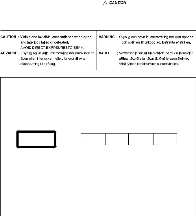
REPRODUCTION AND POSITION OF LABELS
WARNING LABEL
CLASS 1
LASER PRODUCT
CAUTION : Visible and Invisible laser radiation when open and interlock failed or defeated. AVOID DIRECT EXPOSURE TO BEAM. (e)
ADVARSEL : Synlig og usynlig laserstråling når maskinen er åben eller interlocken fejeler. Undgå direkte eksponering til stråling. (d)
VARNING : Synlig och osynling laserstrålning när den öppnas och spärren är urkopplad. Betrakta ej strålen. (s)
VARO : Avattaessa ja suojalukitus ohitettuna tai viallisena olet alttiina näkyvälle ja näkymättömälle lasersäteilylle. Vältä säteen kohdistumista suoraan itseesi. (f)
1-8 (No.MA250)
SECTION 2
SPECIFIC SERVICE INSTRUCTIONS
This service manual does not describe SPECIFIC SERVICE INSTRUCTIONS.
(No.MA250)1-9

SECTION 3
DISASSEMBLY
3.1Main body section
3.1.1Removing the front panel assembly (See Fig.1)
(1)Push the control panel release button in the lower left part of the front panel assembly and remove the front panel assembly.
(2)Take out the front panel assembly.
3.1.2 Removing the bottom cover (See Fig.2)
(1)Turn the main body up side down.
(2)Insert a screwdriver under the joints to release the joints a on the left side, joints b on the right side and joint c on the back side of the main body, then remove the bottom cover from the main body.
Caution:
When releasing the joints using a screwdriver, do not damage the main board.
When remove the bottom cover, do not missing the cooling rubber.
Front panel assembly
Control panel release button
Fig.1
Bottom cover
b
a
b
a
c
Fig.2
1-10 (No.MA250)
3.1.3 |
Removing the front chassis assembly |
|
|
(See Figs.3 and 4) |
|
• Remove the front panel assembly and bottom cover. |
|
|
(1) |
Remove the two screws A on the front side of the main |
Front chassis assembly |
|
body. (See Fig.3) |
|
(2)Remove the two screws B on the both sides of the main body. (See Fig.4)
(3)Release the joints d and joints e on the both sides of the
main body, and then remove the front chassis assembly toward the front. (See Fig.4)
3.1.4Removing the side panel (See Fig.5)
Reference:
Remove the front panel assembly as required.
(1)Remove the two screws C and two screws D attaching the side panel on the left side of the main body.
(2)Take out the side panel from the main body.
A
Fig.3
B B
d |
e |
|
Front chassis assembly
Fig.4
C D D C
Side panel
Fig.5
(No.MA250)1-11

3.1.5Removing the rear bracket (See Fig.6) [except KD-DV6201]
•Remove the bottom cover.
(1)Remove the five screws E, one screw F, two screws G and two screws G attaching the rear bracket on the back side of the main body.
(2)Take out the rear bracket.
3.1.6 Removing the rear bracket (See Fig.6) [For KD-DV6201]
•Remove the bottom cover.
(1)Remove the six screws E, one screw F, two screws G and two screws G attaching the rear bracket on the back side of the main body.
(2)Take out the rear bracket.
for except KD-DV6201
Rear bracket
G H
E |
Composite cable |
F |
|
|
Anntena cord |
for KD-DV6201
Rear bracket
G H
E |
Composite cable |
F |
|
HP cable |
Anntena cord |
|
|
|
|
Fig.6 |
|
1-12 (No.MA250)
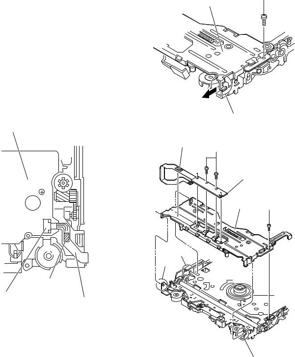
3.1.7 Removing the main board (See Figs.6 to 8)
•Remove the front panel assembly, bottom cover, front chassis assembly and side panel.
(1)Remove the five screws E except KD-DV6201 or six screws E for KD-DV6201 attaching the rear bracket on the back side of the main body. (See Fig.6.)
(2)Remove the three screws J attaching the main board. (See Fig.7)
(3)Disconnect the connector CN961 and take out the main board. (See Fig.7)
(4)Remove the one screw K attaching the USB board. (See Fig.8)
Reference:
Remove the rear bracket as required.
3.1.8Removing the DVD mechanism assembly (See Fig.9)
•Remove the front panel assembly, bottom cover, front chassis assembly, side panel, main board and CD mechanism control board.
(1)Remove the three screws L attaching the top chassis.
(2)Take out the DVD mechanism assembly.
J
Main board
Fig.7
DVD mechanism assembly
Main board
Fig.8
DVD mechanism assembly
L
Fig.9
 J
J
 J
J
K
L
Top chassis
(No.MA250)1-13
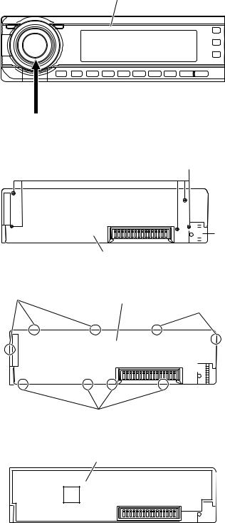
3.1.9Removing the switch board (See Figs.10 to 13)
•Remove the front panel assembly.
(1)Release the main volume knob from the front panel assembly. (See Fig.10)
(2)Remove the five screws M and one screw N attaching the front panel assembly. (See Fig.11)
(3)Release the nine joints f and take out the rear cover. (See Fig.12)
(4)Lift the switch board from the front panel assembly little by little and take out the switch board. (See Fig.13)
Front panel assembly
Volume knob
Fig.10
M


 N
N
Rear cover
Fig.11
f |
Rear cover |
|
f
f
Fig.12
Switch board
Fig.13
1-14 (No.MA250)

3.2DVD mechanism assembly
3.2.1Removing the mechanism control board (See Fig.1)
Caution:
Before disconnecting the flexible wire extending from the DVD pickup, solder the short-circuit point on the flexible wire using a grounding soldering iron. If you do not follow this instruction, the DVD pickup may be damaged.
(1)Turn over the body, and solder the short-circuit points on the flexible wire extending from the DVD pickup.
(2)Disconnect the flexible wire from connector CN101 on the mechanism control board.
(3)Disconnect the card wire from connector CN201 on the mechanism control board.
(4)Disconnect the flexible wire from connector CN202 on the mechanism control board.
(5)Unsolder two soldered points a on the mechanism control board and remove the wire extending from the feed motor.
(6)Remove the screw A attaching the lug wire.
(7)Remove the two screws B and screw C attaching the mechanism control board.
Caution:
•As the flexible wire to be connected to CN101, make sure to attach it to the mechanism control board using a double tape.
•After reassembling, unsolder the short-circuit points.
Flexible wire |
|
Lug wire |
|
|
|
|
|
|
A |
B |
Feed motor |
Double tape |
|
||
|
|
|
a
CN101
C
B
Short-circuit points
CN201 CN202
Mechanism control board
Fig.1
(No.MA250)1-15

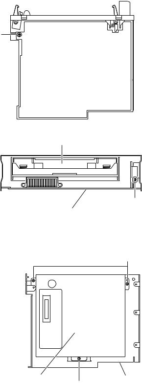
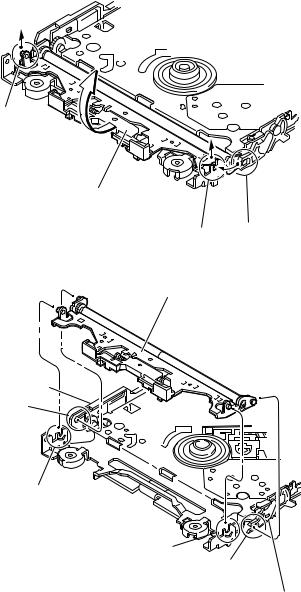
3.2.2Removing the top cover (See Fig.2)
(1)Remove the two screws D attaching the top cover on the back of the body.
(2)Remove the top cover upward.
Reference:
When reassembling, set part b of the top cover under the bending part c of the chassis frame.
3.2.3 Removing the mechanism section (See Fig.2 to 4)
•Remove the top cover.
(1)From the bottom of the body, remove the screw E attaching the lug wire. (See Fig.2.)
(2)Remove the two screws F attaching the right and left stoppers on the front side. (See Fig.2.)
(3)Remove the two floating springs on the bottom of the body. (See Fig.3.)
(4)Move the mechanism section upward and remove from the chassis frame.
The three damper springs come off from the dampers. (See Fig.4.)
Caution:
•When reassembling, reattach the damper spring to the damper respectively and insert the three shafts on the bottom of the mechanism to the dampers.
•Before inserting the shaft to the dampers, apply IPA to the hole of damper.
D
Top cover
D
b
Stopper
F |
c |
E |
|
|
Stopper
F
Lug wire
Fig.2
Floating spring
Fig.3
Mechanism section
Damper SP.(F)
(Silver)  Damper SP.(R)
(Red)
Damper (R) (Purple)
Damper (F) (Black)
Damper SP.(F)
(Silver) Damper (F) Chassis frame (Black)
Fig.4
1-16 (No.MA250)

3.2.4 Removing the clamper unit (See Fig.5 to 7)
•Remove the top cover and the mechanism section.
(1)Remove the clamper2 spring on the bottom of the mechanism section. (See Figs.5.and 6.)
(2)Release the part d of the clamper spring from the bending part of the chassis base assembly. (See Fig.7.)
(3)Move the clamper unit in the direction of the arrow and turn. Release the two joints e and f, then remove the clamper unit upward. (See Fig.6.)
3.2.5 Reattaching the clamper unit (See Fig.5 to 9)
(1)Attach the clamper spring to the clamper unit. (See Fig.8.)
(2)Move the clamper unit to set the side joints e and f to each boss of the chassis base assembly. Make sure that part g is inserted to the notch of the chassis base assembly. (See Figs.5 and 9.)
(3)Move the part d of the clamper spring to the outside of the bending part of the chassis base assembly. (See Fig.7.)
(4)Attach the clamper2 spring to the chassis base assembly. (See Figs.5 and 6.)
Caution:
When reattaching, temporarily hook the end of the clamper spring as shown in the figure to make the work easy. (See Fig.8.)
Clamper unit
g
Clamper spring
f
e
Clamper2 spring
Chassis base assembly
Fig.5
Clamper2 spring
Chassis base assembly
Fig.6
Clamper spring
d
Chassis base assembly
Fig.7
(No.MA250)1-17

Clamper unit
Clamper spring
Fig.8
Clamper unit
g
Notch
Fig.9
1-18 (No.MA250)
3.2.6 Removing the front unit (See Fig.10 to 12)
•Remove the top cover and the mechanism section.
(1)Disconnect the flexible wire from connector CN202 on the mechanism control board at the bottom of the body. (See Fig.10.)
(2)Remove the screw G attaching the front unit on the top of the body. (See Fig.11.)
(3)Move the front unit toward the front to release joint h, and release two joints i and j on the right side of the chassis base assembly. Then remove the front unit upward. (See Figs.11 and 12.)
(4)Remove the two screws H attaching the switch board. (See Fig.12.)
Reference:
You can remove the switch board only without removing the front unit.
Caution:
When reassembling, attach the flexible wire extending from the switch board using the double tape. (See Figs.10 and 12.)
Mechanism control board
Double tape
CN202
Flexible wire
Fig.10
G
Front unit
h
Fig.11
Double tape
H
Switch board
Front unit G
j
i
h
Fig.12
(No.MA250)1-19
3.2.7Removing the loading arm assembly (See Fig.13 , 14)
•Remove the top cover, the mechanism section and the front unit.
(1)From the top of the body, move the loading arm assembly from the front side upward, and release the bosses from the right and left joints k and m of the chassis base assembly.
(2)Release the boss from notch n of the connect arm on the right side of the body, and release the boss from notch p of the slide cam assembly on the left side.
m
Loading arm assembly
k n
Fig.13
Loading arm assembly
Side cam assembly
p
m
k
n
Connect arm
Fig.14
1-20 (No.MA250)
3.2.8 Removing the rod (L)(R)/roller assembly |
|
|
(See Fig.15 and 16) |
|
|
• Remove the top cover, the mechanism section, the front unit |
|
|
and the loading arm assembly. |
Collar |
Collar |
(1)Release the rod (L) and (R) from the joints q at the bottom of the loading arm assembly (See Fig.15.)
(2) Remove the roller assembly from the loading arm assem- |
|
|
bly. (See Fig.16.) |
|
|
(3) Remove the two collars and washer from the roller assem- |
Rod(R) |
Rod(L) |
bly. (See Fig.16.) |
|
|
Caution: |
|
|
After attaching the loading arm assembly to the roller assem- |
|
|
bly, attach the rod (L) and (R). Attach the rods to the right and |
|
|
left collars of the roller. (See Fig.15.) |
|
|
When reattaching the rod (L) and (R) to the loading arm as- |
|
|
sembly, engage each joint as shown in Fig.15. As joints q of |
|
|
the rod (L), let the rod through q before reattaching it. |
|
|
|
q |
q |
|
|
|
|
|
q |
|
|
q |
|
|
|
|
|
|
|
Rod(R) |
|
Rod(L) |
|
|
|
|
|
|
|
|
q |
q |
|
|
|
|
|
|
|
|
|
Loading arm assembly |
|
|
|
|
Fig.15 |
Collar
Washer
Roller assembly
Rod(R)
Collar
Rod(L)
Loading arm assembly
Fig.16
(No.MA250)1-21
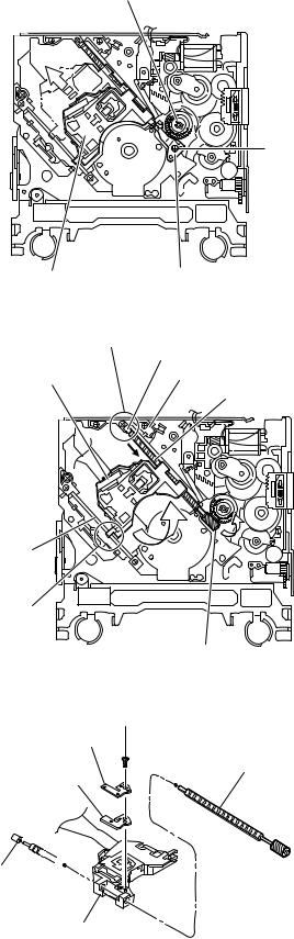
3.2.9Removing the DVD pickup assembly (See Fig.17 to 19)
•Remove the mechanism control board.
(1)From the bottom of the body, turn the feed gear in the direction of the arrow to move the DVD pickup outwards. (See Fig.17.)
(2)Remove the screw J attaching the thrust spring. (See Fig.17.)
(3)Remove the DVD pickup assembly upward on the L.S.gear side and release from sub shaft at joint r. Move the lead screw of the DVD pickup assembly in the direction of the arrow to release from joint s. (See Fig.18.)
Caution:
•When releasing the lead screw at joint s, the L.S.collar comes off at the end of the lead screw. When reassembling, reattach the L.S.collar to the lead screw and engage joint s. (See Fig.18.)
•When reattaching the L.S.collar, reattach it to the point s of the lead screw, and to the rod (M). Make sure that the L.S.collar is set on the rod (M) spring. (See Fig.18.)
(4)Remove the screw K attaching the rack spring/ rack plate on the DVD pickup. (See Fig.19.)
(5)Pull out the lead screw. (See Fig.19.)
Caution:
Perform adjustment after replacing the pickup.
Feed gear
J
DVD Pickup assembly |
Thrust spring |
|
|
||
|
Fig.17 |
|
s |
|
|
|
|
L.S.collar |
DVD Pickup assembly |
|
Rod(M) |
|
|
|
|
|
Lead screw |
Sub shaft
r
L.S.gear
Fig.18
K
Rack spring
Lead screw
Rack plate
L.S.collar
DVD Pickup
Fig.19
1-22 (No.MA250)
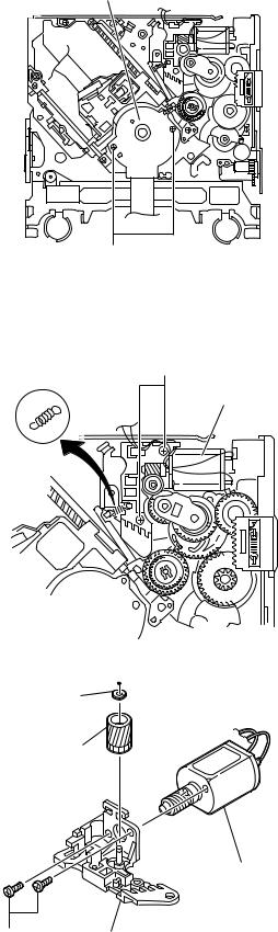
3.2.10 Removing the spindle motor |
|
(See Fig.20) |
|
• Remove the mechanism control board. |
|
Remove the two screws L attaching the spindle motor on the |
Spindle motor |
bottom of the body. |
|
Caution: |
|
Perform adjustment when reattaching the spindle motor. |
|
3.2.11Removing the feed motor assembly (See Fig.21 and 22)
•Remove the mechanism control board.
(1)Remove the feed TRI. spring on the bottom of the body. (See Fig.21.)
(2)Remove the two screws M attaching the feed motor assembly. (See Fig.21.)
(3)Remove the slit washer from the motor H. assembly and
pull out the worm wheel. (See Fig.22.)
Remove the two screws N attaching the feed motor. (See Fig.22.)
L |
Fig.20 |
M
Feed TRI. spring
Feed motor assembly
Fig.21
Slit washer
Worm wheel
Feed motor
N |
Motor H. assembly |
Fig.22
(No.MA250)1-23

SECTION 4 ADJUSTMENT
4.1Test instruments required for adjustment
(1)Digital oscilloscope (199MHz)
(2)Jitter meter
(3)Digital tester
(4)Electric voltmeter
(5)Tracking offset meter
(6)Test Disc : VT501 or VT502
(7)Extension studs : STDV001-3P
(8)Extension cable : EXTDV002-30P
4.3Connection method
4.2Standard measuring conditions
Power supply voltage |
DC14.4V(11 to 16V) |
Load impedance |
4Ω (2 Speakers connection) |
Line Output |
20KΩ |
Caution:
Be sure to attach the heat sink and rear bracket onto the power amplifier IC and regulator IC respectively, before supply the power. If voltage is applied without attaching these parts, the power amplifier IC and regulator IC will be destroyed by heat.
Connection procedure
(1)Attach the front chassis assembly to the main board.
(2)Connect the front panel assembly to the main board.
(3)Attach the heat sink and rear bracket to the main board.
(4)Attach the extension studs to the DVD mechanism assembly.
(5)Connect the DVD mechanism assembly and the main board with a extension cable.
Extension cable
EXTDV002-30P
Heat sink
Extension stud
STDV001-3P
Extension studs
STDV001-3P
1-24 (No.MA250)
4.4Adjustment method for jitter
After replacing the pickup, set the unit in the service mode to display a jitter value on the LCD.
Confirm that the jitter value measured with a jitter meter is within 12% of the jitter value displayed on the LCD. If it is within 12%, then adjustment is not necessary.
If the measured jitter value is outside the 12% tolerance range, perform the following adjustments.
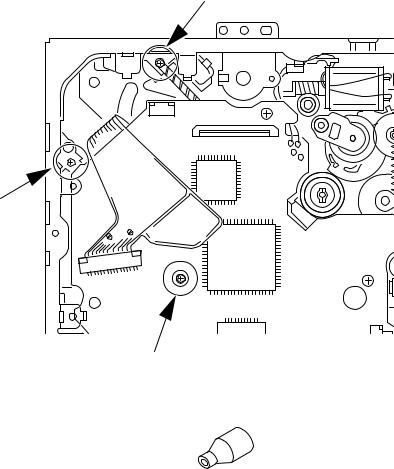
4.4.1 Adjustment procedure
(1)Set the unit to the service mode and display a jitter value (hex data) on the LCD.
(2)Turn each of the screws a, b and c, by a half-turn per step, in the direction that reduces the jitter value in order to minimize it . (Do not turn a screw more than a half turn at a time, but adjust the screws in the cycle of the same level is turned in the pair of b+c and the same level is turned in the pair of a+b.)
(3)After completing the adjustment, secure the screws with screw lock paint.
c
b
a
Jitter value adjustment procedure (Pickup horizontal level adjustment relative to the DVD recording surface)
(For the adjustment tool use a 3 mm wrench and not a screwdriver, this procedure will make the adjustment easier.)
3 mm wrench
(1)Set the unit to the service mode and display a jitter value (hex data) on the LCD.
(2)Turn each of the screws a, b and c, by a half-turn per step, in the direction that reduces the jitter value in order to minimize it.
(Do not turn a screw more than a half turn at a time, but adjust the screw in the cycle of same level turn by pair of b+c→ pair of a+b.)
(3) After completing the adjustment, secure the screws with screw lock paint.
(No.MA250)1-25
4.5Jitter value conversion table
Load the test DVD and set the unit to the service mode. A jitter value converted to the hex value is displayed on the LCD. Refer to the corresponding decimal notation value shown in the following Jitter Conversion Table.
The adjustment is OK if the jitter value measured with a jitter meter is within 12% of the jitter value displayed on the LCD.
If the measured jitter value is outside the 12% tolerance range, adjust it to minimize the difference between the measured value and the displayed value.
Indicated |
Jitter value |
|
Indicated |
|
|
Jitter value |
Indicated |
Jitter value |
|||||
on the LCD |
(%) |
|
|
on the LCD |
|
|
(%) |
on the LCD |
(%) |
||||
|
|
|
|
|
|
|
|
|
|
|
|
|
|
EF56 |
4.7 |
|
|
E79E |
|
|
8.5 |
DFE6 |
12.3 |
||||
EF22 |
4.8 |
|
|
E76A |
|
|
8.6 |
DFB2 |
12.4 |
||||
EEEE |
4.9 |
|
|
E736 |
|
|
8.7 |
DF7E |
12.5 |
||||
EEBA |
5.0 |
|
|
E702 |
|
|
8.8 |
DF4A |
12.6 |
||||
EE86 |
5.1 |
|
|
E6CE |
|
|
8.9 |
DF16 |
12.7 |
||||
EE52 |
5.2 |
|
|
E69A |
|
|
9.0 |
DEE2 |
12.8 |
||||
EE1E |
5.3 |
|
|
E666 |
|
|
9.1 |
DEAE |
12.9 |
||||
EDEA |
5.4 |
|
|
E632 |
|
|
9.2 |
DE7A |
13.0 |
||||
EDB6 |
5.5 |
|
|
E5FE |
|
|
9.3 |
DE46 |
13.1 |
||||
ED82 |
5.6 |
|
|
E5CA |
|
|
9.4 |
DE12 |
13.2 |
||||
ED4E |
5.7 |
|
|
E596 |
|
|
9.5 |
DDDE |
13.3 |
||||
ED1A |
5.8 |
|
|
E562 |
|
|
9.6 |
DDAA |
13.4 |
||||
ECE6 |
5.9 |
|
|
E52E |
|
|
9.7 |
DD76 |
13.5 |
||||
ECB2 |
6.0 |
|
|
E4FA |
|
|
9.8 |
DD42 |
13.6 |
||||
EC7E |
6.1 |
|
|
E4C6 |
|
|
9.9 |
DD0E |
13.7 |
||||
EC4A |
6.2 |
|
|
E492 |
|
|
10.0 |
DCDA |
13.8 |
||||
EC16 |
6.3 |
|
|
E45E |
|
|
10.1 |
DCA6 |
13.9 |
||||
EBE2 |
6.4 |
|
|
E42A |
|
|
10.2 |
DC72 |
14.0 |
||||
EBAE |
6.5 |
|
|
E3F6 |
|
|
10.3 |
DC3E |
14.1 |
||||
EB7A |
6.6 |
|
|
E3C2 |
|
|
10.4 |
DC0A |
14.2 |
||||
EB46 |
6.7 |
|
|
E38E |
|
|
10.5 |
DBD6 |
14.3 |
||||
EB12 |
6.8 |
|
|
E35A |
|
|
10.6 |
DBA2 |
14.4 |
||||
EADE |
6.9 |
|
|
E326 |
|
|
10.7 |
DB6E |
14.5 |
||||
EAAA |
7.0 |
|
|
E2F2 |
|
|
10.8 |
DB3A |
14.6 |
||||
EA76 |
7.1 |
|
|
E2BE |
|
|
10.9 |
DB06 |
14.7 |
||||
EA42 |
7.2 |
|
|
E28A |
|
|
11.0 |
DAD2 |
14.8 |
||||
EA0E |
7.3 |
|
|
E256 |
|
|
11.1 |
DA9E |
14.9 |
||||
E9DA |
7.4 |
|
|
E222 |
|
|
11.2 |
DA6A |
15.0 |
||||
E9A6 |
7.5 |
|
|
E1EE |
|
|
11.3 |
DA36 |
15.1 |
||||
E972 |
7.6 |
|
|
E1BA |
|
|
11.4 |
DA02 |
15.2 |
||||
E93E |
7.7 |
|
|
E186 |
|
|
11.5 |
D9CE |
15.3 |
||||
E90A |
7.8 |
|
|
E152 |
|
|
11.6 |
D99A |
15.4 |
||||
E8D6 |
7.9 |
|
|
E11E |
|
|
11.7 |
D966 |
15.5 |
||||
E8A2 |
8.0 |
|
|
E0EA |
|
|
11.8 |
D932 |
15.6 |
||||
E86E |
8.1 |
|
|
E0B6 |
|
|
11.9 |
D8FE |
15.7 |
||||
E83A |
8.2 |
|
|
E082 |
|
|
12.0 |
D8CA |
15.8 |
||||
E806 |
8.3 |
|
|
E04E |
|
|
12.1 |
D896 |
15.9 |
||||
E7D2 |
8.4 |
|
|
E01A |
|
|
12.2 |
D862 |
16.0 |
||||
|
|
|
|
|
|
|
|
|
|
|
|
|
|
|
|
|
|
|
|
|
|
|
|
|
|
||
|
Calculation |
|
|
|
|
|
|
|
|
||||
|
|
Indicated on the LCD |
Jitter (%) |
|
|
|
|
||||||
|
|
|
|
|
|
|
|
|
|
|
|
|
|
|
|
|
E9A6 |
|
|
7.5 |
|
|
|
|
|
|
|
|
|
|
|
|
|
|
|
|
|
|
|
|
|
|
|
|
|
|
|
|
|
|
|
|
|
|
|
1-26 (No.MA250)

4.6Service mode
4.6.1 Standard input/output conditions
Power supply voltage |
DC14.4V(11 to 16V) |
Load impedance |
4Ω (2 Speakers connection) |
Line Output |
20KΩ |
4.6.2 Service mode setting procedure
(The DVD does not need to be loaded before starting the following procedure.)
[SOURCE] button
[DISC UP] button
[STANDBY/ON ATTENUATOR] button |
|
[SEL] button |
|
[DISC DOWN] button
(1)Press a [STANDBY/ON ATTENUATOR] button on a main unit and switch it on.
(2)Keep this state more than 2 seconds while continuing pressing the [SEL] button, [STANDBY/ON ATTENUATOR] button and [SOURCE] button sequentially.
(3)This unit is set by a service mode.
*Exchanging it operate a menu of a service mode with the [DISC UP] button and [DISC DOWN] button. Operate choice of a menu with a [SEL] button.
4.6.3 Operation procedures
Keep this state more than 2 seconds while continuing pressing the [SEL] button, [STANDBY/ON ATTENUATOR] button and [SOURCE] button sequentially.
The unit enters the service mode.
"INIT ALL" is |
|
|
Press the [SEL] key |
|
|
||||
indicated on the LCD. |
|
|
|
|
|
|
|
|
|
|
|
|
|
|
|
|
|
|
|
|
|
|
|
|
"VERSION" is |
|
|
Press the [SEL] key |
|
|
||||
indicated on the LCD. |
|
|
|
|
|
|
|
||
"AREA/RGN" is |
|
|
Press the [SEL] key |
|
|||
indicated on the LCD. |
|
|
|
|
|
|
|
|
|
|
|
Initialize all data to the factory setting :The system control EEPROM is initialized entirely.
Microcomputer version display
S-XXX-YY System control CPU version/ROM correction version
DVD-XXXX DVD version
USB-XXXX USB version
*Exchanging it operate each indication with the [DISC UP] button and [DISC DOWN] button. Destination area/region display
STS-X XX  System control destination DVD-X XX
  DVD unit destination DVDRGN X
  DVD unit region
*Exchanging it operate each indication with the [DISC UP] button and [DISC DOWN] button.
A B
(No.MA250)1-27
 Loading...