


 Loading...
SERVICE MANUAL
DVD/CD RECEIVER
KD-DV6105,KD-DV6108
|
|
|
KD - DV6105 |
|
|
|
|
|
|
|
Area suffix |
|
|
UT |
------------------------- Taiwan |
|
|
UN |
--------------------------Asean |
|
|
U -------------------- |
Other Areas |
|
|
|
|
|
|
|
|
|
|
|
|
|
|
|
|
|
|
|
|
|
|
|
|
|
|
|
KD-DV6108 |
|
|
|
|
|
|
|
|
|
|
|
|
|
|
|
|
|
|
|
|
|
|
|
|
|
|
|
|
|
|
|
Area suffix |
|
|
|
|
|
|
|
|
|
|
|
|
|
|
A ------------------------ |
Australia |
|
|
|
|
|
|
|
|
|
|
|
|
|
|
UN -------------------------- |
Asean |
|
|
|
|
|
|
|
|
|
|
|
|
|
|
|
|
|
|
|
|
|
|
|
|
|
|
|
|
|
|
|
|
|
|
|
|
|
|
|
|
|
|
|
|
|
|
|
|
TABLE OF CONTENTS
1 PRECAUTIONS . . . . . . . . . . . . . . . . . . . . . . . . . . . . . . . . . . . . . . . . . . . . . . . . . . . . . . . . . . . . . . . . . . . . . . . 1-3 2 SPECIFIC SERVICE INSTRUCTIONS . . . . . . . . . . . . . . . . . . . . . . . . . . . . . . . . . . . . . . . . . . . . . . . . . . . . . . 1-6 3 DISASSEMBLY . . . . . . . . . . . . . . . . . . . . . . . . . . . . . . . . . . . . . . . . . . . . . . . . . . . . . . . . . . . . . . . . . . . . . . . 1-7 4 ADJUSTMENT . . . . . . . . . . . . . . . . . . . . . . . . . . . . . . . . . . . . . . . . . . . . . . . . . . . . . . . . . . . . . . . . . . . . . . . 1-21 5 TROUBLESHOOTING . . . . . . . . . . . . . . . . . . . . . . . . . . . . . . . . . . . . . . . . . . . . . . . . . . . . . . . . . . . . . . . . . 1-29
COPYRIGHT © 2005 Victor Company of Japan, Limited
No.MA158
2005/2
|
|
SPECIFICATION |
|
|
|
|
|
|
|
|
|
|
|
AUDIO AMPLIFIER SECTION |
|
|
|
Maximum Power Output |
|
Front |
50 W per channel |
|
|
|
|
|
|
|
|
|
|
Rear |
50 W per channel |
|
|
|
|
|
|||
Continuous Power Output (RMS) |
Front |
19 W per channel into 4 Ω , 40 Hz to 20 000 Hz at no more |
|||
|
|
|
than 0.8% total harmonic distortion. |
||
|
|
|
|
||
|
|
Rear |
19 W per channel into 4 Ω , 40 Hz to 20 000 Hz at no more |
||
|
|
|
than 0.8% total harmonic distortion. |
||
Load Impedance |
|
|
4 Ω (4 Ω to 8 Ω allowance) |
||
|
|
|
|||
Equalizer Control Range |
|
Frequencies |
60 Hz, 150 Hz, 400 Hz, 1 kHz, 2.4 kHz, 6 kHz, 15 kHz |
||
|
|
|
|
|
|
|
|
Level |
±10 dB |
|
|
|
|
|
|
|
|
Signal-to-Noise Ratio |
|
|
70 dB |
|
|
|
|
|
|
||
Audio Output Level |
|
Analog (2nd AUDIO OUT) |
6 mW (at 16 Ω ) |
|
|
|
|
|
|
||
|
|
Digital (DIGITAL OUT: Optical) |
Signal wave length : 660 nm |
||
|
|
|
Output level : -21 dBm to -15 dBm |
||
|
|
|
|
||
|
|
Line-Out Level/Impedance |
5.0 V/20 kΩ load (full scale) |
||
|
|
|
|
|
|
|
|
Output Impedance |
1 kΩ |
|
|
|
|
|
|
||
Subwoofer-Out Level/Impedance |
|
|
2.0 V/20 kΩ load (full scale) |
||
|
|
|
|
||
Color System |
|
PAL/NTSC |
|
||
|
|
|
|
||
Video Output (composite) |
|
1 Vp-p/75 Ω |
|
||
|
|
|
|||
Other Terminals |
|
LINE IN, CD changer |
|||
|
|
|
|
|
|
|
|
TUNER SECTION |
|
|
|
|
|
|
|||
Frequency Range |
|
FM |
87.5 MHz to 108.0 MHz |
||
|
|
|
|
||
|
|
AM |
531 kHz to 1 602 kHz |
||
|
|
|
|
||
FM Tuner |
|
Usable Sensitivity |
11.3 dBf (1.0 µV/75 Ω ) |
||
|
|
|
|
||
|
|
50 dB Quieting Sensitivity |
16.3 dBf (1.8 µV/75 Ω ) |
||
|
|
|
|
|
|
|
|
Alternate Channel Selectivity (400 kHz) |
65 dB |
|
|
|
|
|
|
|
|
|
|
Frequency Response |
40 Hz to 15 000 Hz |
|
|
|
|
|
|
|
|
|
|
Stereo Separation |
35 dB |
|
|
|
|
|
|
|
|
|
|
Capture Ratio |
1.5 dB |
|
|
|
|
|
|
|
|
AM Tuner |
|
Sensitivity |
20 µV |
|
|
|
|
|
|
|
|
|
|
Selectivity |
35 dB |
|
|
|
|
|
|
|
|
|
|
DVD/CD PLAYER SECTION |
|
|
|
Signal Detection System |
|
Non-contact optical pickup (semiconductor laser) |
|||
|
|
|
|
||
Number of Channels |
|
2 channels (stereo) |
|
||
|
|
|
|
||
Frequency Response |
|
DVD, fs=48 kHz/96 kHz |
16 Hz to 22 000 Hz |
|
|
|
|
|
|
|
|
|
|
VCD, CD, MP3, WMA |
16 Hz to 20 000 Hz |
|
|
|
|
|
|
|
|
Dynamic Range |
|
|
96 dB |
|
|
|
|
|
|
|
|
Signal-to-Noise Ratio |
|
98 dB |
|
|
|
|
|
|
|||
Wow and Flutter |
|
Less than measurable limit |
|||
|
|
|
|||
MP3 (MPEG Audio Layer 3) |
|
Max. Bit Rate: 320 kbps |
|||
|
|
|
|||
WMA (Windows Media Audio) |
|
Max. Bit Rate: 192 kbps |
|||
|
|
|
|
|
|
|
|
GENERAL |
|
|
|
|
|
|
|||
Power Requirement |
|
Operating Voltage |
DC 14.4 V (11 V to 16 V allowance) |
||
|
|
|
|
|
|
Grounding System |
|
|
Negative ground |
|
|
|
|
|
|
||
Allowable Operating Temperature |
|
0°C to +40°C |
|
||
|
|
|
|
|
|
Dimensions (W × H × D) |
|
Installation Size (approx.) |
182 mm × |
52 mm × |
158 mm |
|
|
|
|
|
|
|
|
Panel Size (approx.) |
188 mm × |
58 mm × |
11 mm |
|
|
|
|
||
Mass (approx.) |
|
|
1.7 kg (excluding accessories) |
||
|
|
|
|
||
Design and specifications are subject to change without notice. |
|
|
|
||
1-2 (No.MA158)

SECTION 1
PRECAUTIONS
1.1Safety Precautions
!


 Burrs formed during molding may be left over on some parts of the chassis. Therefore,
pay attention to such burrs in the case of preforming repair of this system.
! |
Please use enough caution not to see the beam directly or touch it in case of an |
|
adjustment or operation check. |
|
|
(No.MA158)1-3

1.2Preventing static electricity
Electrostatic discharge (ESD), which occurs when static electricity stored in the body, fabric, etc. is discharged, can destroy the laser diode in the traverse unit (optical pickup). Take care to prevent this when performing repairs.
1.2.1Grounding to prevent damage by static electricity
Static electricity in the work area can destroy the optical pickup (laser diode) in devices such as CD players. Be careful to use proper grounding in the area where repairs are being performed.
(1)Ground the workbench
Ground the workbench by laying conductive material (such as a conductive sheet) or an iron plate over it before placing the traverse unit (optical pickup) on it.
(2)Ground yourself
Use an anti-static wrist strap to release any static electricity built up in your body.
(caption)
Anti-static wrist strap
1M
Conductive material (conductive sheet) or iron plate
(3)Handling the optical pickup
•In order to maintain quality during transport and before installation, both sides of the laser diode on the replacement optical pickup are shorted. After replacement, return the shorted parts to their original condition.
(Refer to the text.)
•Do not use a tester to check the condition of the laser diode in the optical pickup. The tester's internal power source can easily destroy the laser diode.
1.3Handling the traverse unit (optical pickup)
(1)Before disconnecting the flexible wire from the connector CN101 on the mechanism control board, solder the short-circuit points on the flexible wire.
Caution:
If you do not follow this instruction, the DVD pickup may be damaged.
(2)Disconnect the flexible wire from the connector CN101 on the mechanism control board.
(3)Remove the solders from the short-circuit points on the flexible wire after replacing the DVD pickup.
(4)Connect the flexible wire to the connector CN101 on the mechanism control board.
Flexible wire
CN101
Short-circuit points
Mechanism control board
1-4 (No.MA158)

1.4Important for laser products
1.CLASS 1 LASER PRODUCT
2.DANGER : Invisible laser radiation when open and inter lock failed or defeated. Avoid direct exposure to beam.
3.CAUTION : There are no serviceable parts inside the Laser Unit. Do not disassemble the Laser Unit. Replace the complete Laser Unit if it malfunctions.
4.CAUTION : The CD,MD and DVD player uses invisible laser radiation and is equipped with safety switches which prevent emission of radiation when the drawer is open and the safety interlocks have failed or are defeated. It is dangerous to defeat the safety switches.
5.CAUTION : If safety switches malfunction, the laser is able
to function.
6.CAUTION : Use of controls, adjustments or performance of procedures other than those specified here in may result in hazardous radiation exposure.
! |
|
Please use enough caution not to |
|||
|
|
see the beam directly or touch it |
|||
|
|
in case of an adjustment or operation |
|||
|
|
check. |
|||
|
|
|
|
|
|
|
|
|
|
|
|
|
|
|
|
|
|
REPRODUCTION AND POSITION OF LABELS
WARNING LABEL
CLASS 1
LASER PRODUCT
CAUTION : Visible and Invisible laser radiation when open and interlock failed or defeated. AVOID DIRECT EXPOSURE TO BEAM. (e)
ADVARSEL : Synlig og usynlig laserstråling når maskinen er åben eller interlocken fejeler. Undgå direkte eksponering til stråling. (d)
VARNING : Synlig och osynling laserstrålning när den öppnas och spärren är urkopplad. Betrakta ej strålen. (s)
VARO : Avattaessa ja suojalukitus ohitettuna tai viallisena olet alttiina näkyvälle ja näkymättömälle lasersäteilylle. Vältä säteen kohdistumista suoraan itseesi. (f)
(No.MA158)1-5
SECTION 2
SPECIFIC SERVICE INSTRUCTIONS
This service manual does not describe SPECIFIC SERVICE INSTRUCTIONS.
1-6 (No.MA158)

SECTION 3
DISASSEMBLY
3.1Main body section
3.1.1Removing the front panel assembly (See Fig.1)
Push the detach button in the lower left part of the front panel assembly and remove the front panel assembly.
3.1.2Removing the bottom cover (See Fig.2)
Reference:
Remove the front panel assembly as required.
(1)Release the two joints a, two joints b and joint c.
(2)Remove the bottom cover from the main body.
Caution:
Do not damage the main board when releasing the joints using a screwdriver or a similar tool.
Front panel assembly
Detach button
Fig.1
Bottom cover
b |
|
a |
||
|
|
|
|
|

 a b
a b 
c
Fig.2
(No.MA158)1-7

3.1.3 Removing the front chassis assembly (See Figs.3 and 4)
•Remove the front panel assembly and bottom cover.
(1)From the front side of the main body, remove the two screws A attaching the front chassis assembly. (See Fig.3.)
(2)From the both sides of the main body, remove the two screws B attaching the front chassis assembly. (See Fig.4.)
(3)Release the two joints d and two joints e. (See Fig.4.)
3.1.4Removing the side heat sink (See Fig.5)
Reference:
Remove the front panel and front chassis assemblies as required.
From the left side of the main body, remove the two screws C and three screws D attaching the side heat sink.
Front chassis assembly
A
Fig.3
d |
e |
B B
d |
e |
Front chassis assembly
Fig.4
C
Side heat sink
D
Fig.5
1-8 (No.MA158)
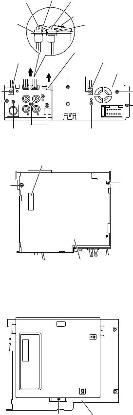
3.1.5Removing the rear bracket (See Fig.6)
•Remove the bottom cover.
(1)From the back side of the main body, remove the two screws E, two screws E', screw F, two screws G and three screws H attaching the rear bracket.
(2)Remove the LINE IN, SUBWOOFER and AUDIO OUT cables from the rear bracket in the direction of the arrow.
Reference:
•When attaching the LINE IN and SUBWOOFER cables, insert them in the slots of the rear bracket and hang them on a wire holder.
•When attaching the screws E', attach the cable holders with them.
3.1.6 Removing the main board (See Figs.6 and 7)
•Remove the front panel assembly, bottom cover, front chassis assembly and side heat sink.
Reference:
Remove the rear bracket as required.
(1)From the back side of the main body, remove the three screws H attaching the main board. (See Fig.6.)
(2)From the bottom side of the main body, remove the three screws J attaching the main board. (See Fig.7.)
(3)Disconnect the connector CN961 on the main board from the DVD mechanism assembly and take out the main board from the main body. (See Fig.7.)
SUBWOOFER cable |
Slot |
LINE IN cable |
|
Wire holder
Rear bracket
Slot
|
|
AUDIO OUT cable |
|
Cable holder |
|
Cable holder |
|
|
H |
E' |
Rear bracket |
|
|
||
E' |
|
|
E |
H |
|
|
H |
|
|
|
|
F |
G |
E |
|
|
Fig.6 |
|
|
|
CN961 |
|
|
J |
|
|
J |
|
|
|
|
 J
J
3.1.7Removing the DVD mechanism assembly (See Fig.8)
•Remove the front panel assembly, bottom cover, front chassis assembly, side heat sink and main board.
(1)From the inside of the top chassis, remove the three screws K attaching the DVD mechanism assembly.
(2)Take out the DVD mechanism assembly from the top chassis.
Main board
Fig.7
DVD mechanism assembly
K


 K
K
K |
Top chassis |
Fig.8
(No.MA158)1-9
Loading...