


Illustrated Parts Manual
Models
400RTS
500RTS
P/N
3120830
September 30, 2013


REVISION LOG
June 1, 1993 - Original Issue Of Manual
January 1996 - Revised
December 1997 - Revised
November 11, 1999 - Updated Page 7-3, 7-5, 7-14 & 7-15
July 18, 2000 - Revised
July 11, 2003 - Revised (Manual edited to 0010488 Revision 36 - 400RTS)
(Manual edited to 0010458 Revision 59 - 500RTS)
February 4, 2004 - Revised (Manual edited to 0010458 Revision 62 - 500RTS)
June 14, 2004 - Revised (Manual edited to 0010458 Revision 63 - 500RTS)
June 30, 2007 - Revised (Manual edited to 0010458 Revision 69 - 500RTS)
March 1, 2011 - Revised
September 30, 2013 - Revised
3120830 400RTS 500RTS A

REVISION LOG
B 400RTS 500RTS 3120830

TABLE OF CONTENTS
FIGURE NO. TITLE PAGE NO.
SECTION 1 - FRAME . . . . . . . . . . . . . . . . . . . . . . . . . . . . . . . . . . . . . . . . . . . . . . . . . . . . . .1-1
1-1 FRAME, STEERING, AND AXLE INSTALLATIONS . . . . . . . . . . . . . . . . . . . . . . . . . . . . 1-2
1-2 TIRE AND WHEEL DRIVE INSTALLATIONS . . . . . . . . . . . . . . . . . . . . . . . . . . . . . . . . . 1-8
1-3 DRIVE MOTOR ASSEMBLY. . . . . . . . . . . . . . . . . . . . . . . . . . . . . . . . . . . . . . . . . . . . . . 1-12
1-4 DRIVE BRAKE ASSEMBLY . . . . . . . . . . . . . . . . . . . . . . . . . . . . . . . . . . . . . . . . . . . . . . 1-14
1-5 DRIVE HUB ASSEMBLIES. . . . . . . . . . . . . . . . . . . . . . . . . . . . . . . . . . . . . . . . . . . . . . . 1-18
1-6 DRIVE HUB/BRAKE ASSEMBLIES . . . . . . . . . . . . . . . . . . . . . . . . . . . . . . . . . . . . . . . . 1-22
1-7 FRAME MOUNTED COMPONENTS INSTALLATION . . . . . . . . . . . . . . . . . . . . . . . . . . 1-28
1-8 FRAME MOUNTED OPTIONS INSTALLATION. . . . . . . . . . . . . . . . . . . . . . . . . . . . . . . 1-34
1-9 TOW PACKAGE INSTALLATION - BALL (OPTIONAL) . . . . . . . . . . . . . . . . . . . . . . . . . 1-38
1-10 TOW PACKAGE INSTALLATION - PINTLE HOOK (OPTIONAL). . . . . . . . . . . . . . . . . . 1-40
SECTION 2 - GROUND CONTROLS . . . . . . . . . . . . . . . . . . . . . . . . . . . . . . . . . . . . . . . . . .2-1
2-1 CONTROL VALVES AND TANKS INSTALLATION . . . . . . . . . . . . . . . . . . . . . . . . . . . . . 2-2
2-2 CONTROL VALVE ASSEMBLY (PRIOR TO S/N 107516). . . . . . . . . . . . . . . . . . . . . . . . 2-8
2-3 CONTROL VALVE ASSEMBLY (S/N 107516 TO PRESENT) . . . . . . . . . . . . . . . . . . . . . 2-12
2-4 ENGINE INSTALLATION - FORD VSG-411 . . . . . . . . . . . . . . . . . . . . . . . . . . . . . . . . . . 2-14
2-5 DUAL FUEL COMPONENTS INSTALLATION - FORD VSG-411 ENGINE OPTION . . . 2-20
2-6 110 VOLT GENERATOR INSTALLATION (FORD VSG-411) (OPTIONAL). . . . . . . . . . . 2-24
2-7 ENGINE INSTALLATION - FORD LSG-423 . . . . . . . . . . . . . . . . . . . . . . . . . . . . . . . . . . 2-26
2-8 ENGINE INSTALLATION - FORD LRG-423 DIS/LRG-425 . . . . . . . . . . . . . . . . . . . . . . . 2-32
2-9 DUAL FUEL COMPONENTS INSTALLATION - FORD LSG-423/LRG-423 DIS/
LRG-425 . . . . . . . . . . . . . . . . . . . . . . . . . . . . . . . . . . . . . . . . . . . . . . . . . . . . . . . . . . 2-38
2-10 GENERATOR INSTALLATION - FORD LSG-423/LRG-423/LRG-425 . . . . . . . . . . . . . . . 2-42
2-11 ENGINE INSTALLATION - DEUTZ F3L1011. . . . . . . . . . . . . . . . . . . . . . . . . . . . . . . . . . 2-46
2-12 110 VOLT GENERATOR INSTALLATION - DEUTZ (OPTIONAL). . . . . . . . . . . . . . . . . . 2-54
2-13 PUMP ASSEMBLY - SUNSTRAND . . . . . . . . . . . . . . . . . . . . . . . . . . . . . . . . . . . . . . . . . 2-58
2-14 PUMP ASSEMBLY - BARNES . . . . . . . . . . . . . . . . . . . . . . . . . . . . . . . . . . . . . . . . . . . . 2-62
2-15 GROUND CONTROL BOX INSTALLATION . . . . . . . . . . . . . . . . . . . . . . . . . . . . . . . . . . 2-64
2-16 HOODS AND BEACON LIGHT INSTALLATION. . . . . . . . . . . . . . . . . . . . . . . . . . . . . . . 2-70
SECTION 3 - SCISSORS ARMS . . . . . . . . . . . . . . . . . . . . . . . . . . . . . . . . . . . . . . . . . . . . .3-1
3-1 SIZZORS ARMS INSTALLATION - 400RTS (PRIOR TO S/N 41058) . . . . . . . . . . . . . . 3-2
3-2 SIZZORS ARMS INSTALLATION - 400RTS (S/N 41058 TO PRESENT). . . . . . . . . . . . 3-6
3-3 SIZZORS ARMS INSTALLATION - 500RTS (PRIOR TO S/N 27997) . . . . . . . . . . . . . . 3-10
3-4 SIZZORS ARMS INSTALLATION - 500RTS (S/N 27997 TO PRESENT). . . . . . . . . . . . 3-14
3-5 SIZZORS ARMS GUARD INSTALLATION - 500RTS. . . . . . . . . . . . . . . . . . . . . . . . . . . 3-18
3-6 SIZZORS ARMS GUARD INSTALLATION - 400RTS. . . . . . . . . . . . . . . . . . . . . . . . . . . 3-20
SECTION 4 - PLATFORM. . . . . . . . . . . . . . . . . . . . . . . . . . . . . . . . . . . . . . . . . . . . . . . . . . .4-1
4-1 FIXED PLATFORM (STANDARD), HANDRAILS AND OPTIONAL COMPONENTS
INSTALLATION . . . . . . . . . . . . . . . . . . . . . . . . . . . . . . . . . . . . . . . . . . . . . . . . . . . . . 4-2
4-2 PLATFORM EXTENSION INSTALLATION (OPTIONAL). . . . . . . . . . . . . . . . . . . . . . . . . 4-8
4-3 PLATFORM EXTENSION INSTALLATION - MEGADECK (OPTIONAL) . . . . . . . . . . . . . 4-12
4-4 POWER DECK EXTENSION AND PLATFORM ASSEMBLY . . . . . . . . . . . . . . . . . . . . . 4-16
4-5 PLATFORM CONSOLE BOX ASSEMBLY . . . . . . . . . . . . . . . . . . . . . . . . . . . . . . . . . . . 4-20
4-6 DRIVE/LIFT CONTROLLER ASSEMBLY (PRIOR TO S/N 57701) . . . . . . . . . . . . . . . . . 4-26
4-7 DRIVE/LIFT CONTROLLER ASSEMBLY (S/N 57701 TO PRESENT). . . . . . . . . . . . . . . 4-28
3120830 400RTS 500RTS i

TABLE OF CONTENTS
FIGURE NO. TITLE PAGE NO.
SECTION 5 - CYLINDER . . . . . . . . . . . . . . . . . . . . . . . . . . . . . . . . . . . . . . . . . . . . . . . . . . .5-1
5-1 AXLE LOCKOUT CYLINDER ASSEMBLY (OSCILLATING CYLINDER) (OPTIONAL) . . 5-2
5-2 LEVELING JACK CYLINDER ASSEMBLY (HYDRAULIC JACK OPTION)
(PRIOR TO S/N 104832) . . . . . . . . . . . . . . . . . . . . . . . . . . . . . . . . . . . . . . . . . . . . . . 5-4
5-3 LEVELING JACK CYLINDER ASSEMBLY (HYDRAULIC JACK OPTION)
(S/N 104832 TO PRESENT) . . . . . . . . . . . . . . . . . . . . . . . . . . . . . . . . . . . . . . . . . . . 5-6
5-4 LIFT CYLINDER ASSEMBLIES. . . . . . . . . . . . . . . . . . . . . . . . . . . . . . . . . . . . . . . . . . . . 5-8
5-5 PLATFORM EXTENSION CYLINDER ASSEMBLY. . . . . . . . . . . . . . . . . . . . . . . . . . . . . 5-12
5-6 STEER CYLINDER ASSEMBLY (MACHINES BUILT PRIOR TO JUNE 1993) . . . . . . . . 5-14
5-7 STEER CYLINDER ASSEMBLY (MACHINES BUILT JUNE 1993 TO PRESENT) . . . . . 5-16
SECTION 6 - HYDRAULIC . . . . . . . . . . . . . . . . . . . . . . . . . . . . . . . . . . . . . . . . . . . . . . . . . .6-1
6-1 HYDRAULIC DIAGRAM - AUXILIARY POWER . . . . . . . . . . . . . . . . . . . . . . . . . . . . . . . . 6-2
6-2 HYDRAULIC DIAGRAM - OSCILLATING AXLE (OPTIONAL). . . . . . . . . . . . . . . . . . . . . 6-4
6-3 HYDRAULIC DIAGRAM - PLATFORM EXTENSION. . . . . . . . . . . . . . . . . . . . . . . . . . . . 6-6
6-4 HYDRAULIC DIAGRAM - STANDARD 2WD/2WS . . . . . . . . . . . . . . . . . . . . . . . . . . . . . 6-10
6-5 HYDRAULIC DIAGRAM - STANDARD 4WD/2WS . . . . . . . . . . . . . . . . . . . . . . . . . . . . . 6-16
6-6 HYDRAULIC DIAGRAM - STANDARD 4WD/4WS . . . . . . . . . . . . . . . . . . . . . . . . . . . . . 6-22
6-7 HYDRAULIC DIAGRAM - STANDARD 2WD/4WS . . . . . . . . . . . . . . . . . . . . . . . . . . . . . 6-28
6-8 HYDRAULIC DIAGRAM - TOW PACKAGE (OPTIONAL) . . . . . . . . . . . . . . . . . . . . . . . . 6-34
6-9 HYDRAULIC DIAGRAM LIST . . . . . . . . . . . . . . . . . . . . . . . . . . . . . . . . . . . . . . . . . . . . . 6-36
SECTION 7 - ELECTRICAL . . . . . . . . . . . . . . . . . . . . . . . . . . . . . . . . . . . . . . . . . . . . . . . . .7-1
7-1 ELECTRICAL DIAGRAM LIST. . . . . . . . . . . . . . . . . . . . . . . . . . . . . . . . . . . . . . . . . . . . . 7-2
7-2 WIRING DIAGRAM - 0610114 CIRCUIT CARD . . . . . . . . . . . . . . . . . . . . . . . . . . . . . . . 7-8
7-3 WIRING DIAGRAM - DUAL FUEL (FORD) . . . . . . . . . . . . . . . . . . . . . . . . . . . . . . . . . . . 7-9
7-4 WIRING DIAGRAM - 110 VOLT GENERATOR (FORD) . . . . . . . . . . . . . . . . . . . . . . . . . 7-10
7-5 WIRING DIAGRAM - 110 VOLT GENERATOR (DEUTZ) . . . . . . . . . . . . . . . . . . . . . . . . 7-11
7-6 WIRING DIAGRAM - STANDARD 500RTS (FORD LRG-425 GAS MACHINES) . . . . . . 7-12
7-7 WIRING DIAGRAM - STANDARD 500RTS (DEUTZ DIESEL MACHINES). . . . . . . . . . . 7-14
7-8 WIRING DIAGRAM - AUSTRALIAN SPEC 500RTS (DEUTZ DIESEL MACHINES) . . . . 7-16
SECTION 8 - DECALS . . . . . . . . . . . . . . . . . . . . . . . . . . . . . . . . . . . . . . . . . . . . . . . . . . . . . 8-1
8-1 DECALS INSTALLATION - COMMON . . . . . . . . . . . . . . . . . . . . . . . . . . . . . . . . . . . . . . 8-2
SECTION 9 - RECOMMENDED SERVICE PARTS STOCK . . . . . . . . . . . . . . . . . . . . . . . . . 9-1
SECTION 10 - SPECIAL OPTIONS . . . . . . . . . . . . . . . . . . . . . . . . . . . . . . . . . . . . . . . . . . .10-1
SECTION 11 - PART NUMBER INDEX . . . . . . . . . . . . . . . . . . . . . . . . . . . . . . . . . . . . . . . .11-1
ii 400RTS 500RTS 3120830

SECTION 1
FRAME
3120830 400RTS 500RTS 1-1
SECTION 1 FRAME
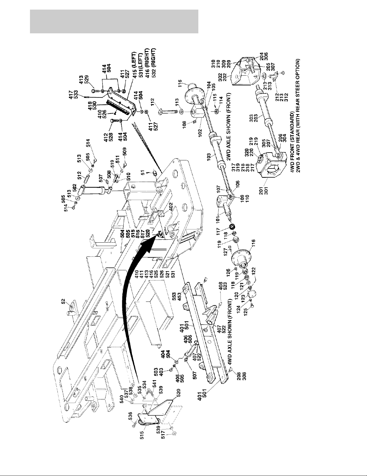
FIGURE 1-1. FRAME, STEERING, AND AXLE INSTALLATIONS
1-2 400RTS 500RTS 3120830

SECTION 1 FRAME
FIGURE 1-1. FRAME, STEERING, AND AXLE INSTALLATIONS
ITEM # PART NUMBER QTY. DESCRIPTION REV.
Ref. FRAME, STEERING AND AXLE INSTALLATIONS
Ref. FRAME WELDMENT - 2WS OPTIONS:
2360364 Ref. FRAME WELDMENT (PRIOR TO S/N 46528) 8
2360491 Ref. FRAME WELDMENT (S/N 46528 TO PRESENT) 2
1 0961739 2 Bushing, Bronze (Sizzor Arm Pivot)
Ref. FRAME WELDMENT - 4WS OPTIONS:
2360358 Ref. FRAME WELDMENT (PRIOR TO S/N 46528) 9
2360492 Ref. FRAME WELDMENT (S/N 46528 TO PRESENT) 2
51 0961739 2 Bushing, Bronze (Sizzor Arm Pivot)
52 0961029 4 Bushing, Bronze (Kingpin Pivot)
0252790 Ref. STEERING INSTALLATION - 2WD FRONT (STANDARD
PARTS)
101 4130287 1 Spindle Weldment (R.H.)
0960523 2 Bushing, Bronze (Kingpin)
102 4130288 1 Spindle Weldment (L.H.)
0960523 2 Bushing, Bronze (Kingpin)
103 1 Steer Cylinder Assembly (See Section 5 for Breakdown)
Options:
Use 1682967 Standard (Prior to June 1993) (was p/n 1682681)
1682967 Standard (June 1993 to Present)
104 1660204 1 Rod-End (Left Side)
105 3322602 1 Nut, Jam 1" - 12NF Right Hand Threads (Left Side)
106 1660205 1 Rod-End (Right Side)
107 3300228 1 Nut, Jam 1"-12" NF Left Hand Threads (Right Side)
108 2160002 2 Fitting, Grease
109 0642622 2 Bolt 1" - 8NC x 2 3/4"
110 4712600 2 Flatwasher 1" Narrow
111 Not Used
112 3421243 2 Kingpin
113 0440183 2 Bearing, Thrust
114 3323403 2 Nut, Slotted 1 1/2"-12NF
115 3451012 2 Pin, Cotter 5/16" x 3"
116 2780177 2 Hub, Wheel
117 3960353 2 Seal, Oil
118 0440174 4 Cup, Bearing
119 0440175 4 Cone, Bearing
120 3322603 2 Nut, Slotted 1" -12NF
121 4740034 2 Washer, Hardened
122 3450610 2 Pin, Cotter 3/16" x 2 1/2"
123 1120311 2 Cap, Hub
124 0721004 6 Screw, Machine #10-24NC x 1/2"
125 4761000 6 Lockwasher #10
126 3300012 18 Nut, Wheel
3
3120830 400RTS 500RTS 1-3

SECTION 1 FRAME
FIGURE 1-1. FRAME, STEERING, AND AXLE INSTALLATIONS (CONTINUED)
ITEM # PART NUMBER QTY. DESCRIPTION REV.
127 0630137 18 Stud, Wheel
_ _ _ _ _ _ _ _ _ _ _ _ _ _ _ _ _ _
0100019 A/R Loctite #271
0100011 A/R Loctite #242
0253078 Ref. STEERING INSTALLATION - 4WD FRONT (STANDARD
PARTS WITH 2WS)
0253059 Ref. STEERING INSTALLATION - 2WD REAR (STANDARD PARTS
WHEN EQUIPPED WITH OPTIONAL
REAR STEER)
201 4130279 1 Spindle Weldment (Right Side - Front/Left Side - Rear)
202 4130280 1 Spindle Weldment (Left Side - Front/Right Side - Rear)
203 1 Steer Cylinder Assembly (See Section 5 for Breakdown)
Options:
1682681 Standard (Prior to June 1993)
1682967 Standard (June 1993 to Present)
204 1660204 1 Rod-End
205 3322602 1 Nut, Jam 1"-12NF
206 1660205 1 Rod-End
207 3300228 1 Nut, Jam 1"-12NF Left Hand Thread
208 2160003 4 Fitting, Grease - 45°
209 0642622 2 Bolt 1"-8NC x 2 3/4"
210 4712600 A/R Flatwasher 1" Narrow
211 Not Used
212 3421190 4 Kingpin
213 0440161 4 Bearing, Thrust
214 to 216 Not Used
217 0641608 8 Bolt 3/8"-16NC x 1"
218 4751600 8 Flatwasher 3/8"
219 1380124 8 Clip, Retainer (Prior to S/N 69836)
220 4920096 4 ft./1.2m Wire, Safety (4 Pieces 1 ft./30 cm Long) (Prior to S/N 69836)
— — — — — — — — — —
0100019 A/R Loctite #271
0100011 A/R Loctite #242
6
9
0252532 Ref. STEERING INSTALLATION - 4WD FRONT AND REAR (STAN-
DARD PARTS WHEN EQUIPPED WITH OPTIONAL REAR
STEER)
301 4130279 1 Spindle Weldment (Right Side - Front/Left Side-Rear)
302 4130280 2 Spindle Weldment (Left Side - Front/Right Side - Rear)
303 2 Steer Cylinder Assembly (See Section 5 for Breakdown)
Options:
1682681 Prior to June 1993
1682967 June 1993 to Present
304 1660204 2 Rod-End
305 3322602 2 Nut, Jam 1"-12NF
306 1660205 2 Rod-End
307 3300228 2 Nut, Jam 1"-12NF Left Hand Thread
8
1-4 400RTS 500RTS 3120830

SECTION 1 FRAME
FIGURE 1-1. FRAME, STEERING, AND AXLE INSTALLATIONS (CONTINUED)
ITEM # PART NUMBER QTY. DESCRIPTION REV.
308 2160003 8 Fitting, Grease - 45°
309 0642622 4 Bolt 1"-8NC x 2 3/4"
310 4712600 A/R Flatwasher 1" Narrow
311 Not Used
312 3421190 8 Kingpin
313 0440161 8 Bearing, Thrust
314 to 316 Not Used
317 0641608 16 Bolt 3/8"-16NC x 1"
318 4751600 16 Flatwasher 3/8"
319 1380124 16 Clip, Retainer (Prior to S/N 69836)
320 4920096 8 ft./2.4m Wire, Safety (8 Pieces 1 ft./30cm long) (Prior to S/N 69836)
— — — — — — — — — —
0100019 A/R Loctite #271
Ref. FIXED AXLE INSTALLATIONS (STANDARD PARTS)
0253171 Ref. FIXED AXLE INSTALLATION - 2WD 4
0253172 Ref. FIXED AXLE INSTALLATION - 4WD 4
401 1 Axle Weldment - 2WD Options:
4844129 Prior to October 1994
4844868 October 1994 to Present
0961029 4 Bushing, Bronze (Kingpin Pivot)
1 Axle Weldment - 4WD Options:
4844059 Prior to October 1994
4844867 October 1994 to Present
0961029 4 Bushing, Bronze (Kingpin Pivot)
402 0560901 2 Block, Stop
403 0641610 1 Bolt 3/8"-16NC x 1 1/4"
404 4740185 2 Flatwasher
405 Not Used
406 1 Pin Weldment Options:
4842621 Prior to October 1994
3422401 October 1994 to Present
407 Not Used
408 3780183 2 O-Ring (October 1994 to Present)
409 4640812 1 Valve, Relief (October 1994 to Present - Not Shown)
410 3820030 6 Rivet, Pop 3/16" (Prior to S/N 77909)
411 3311605 8 Nut 3/8"-16NC (September 1995 to Present)
412 0641612 4 Bolt 3/8" x 1 1/2"-16NC (September 1995 to Present)
413 0641614 4 Bolt 3/8" x 1 3/4"-16NC (September 1995 to Present)
414 4751600 16 Flatwasher (September 1995 to Present)
415 0902214 1 Bracket, L.H. (September 1995 to Present)
416 0902215 1 Bracket, R.H. (September 1995 to Present)
417 3440616 4 Pin, Roll 3/16" x 1" (September 1995 to Present)
418 4280298 2 Strip, Wear (Prior to S/N 77909)
3120830 400RTS 500RTS 1-5

SECTION 1 FRAME
FIGURE 1-1. FRAME, STEERING, AND AXLE INSTALLATIONS (CONTINUED)
ITEM # PART NUMBER QTY. DESCRIPTION REV.
Ref. OSCILLATING AXLE INSTALLATION - OPTION (STANDARD
PARTS WHEN EQUIPPED)
0253381 Ref. OSCILLATING AXLE INSTALLATION - 2WD 11
0253380 Ref. OSCILLATING AXLE INSTALLATION - 4WD 10
501 1 Axle Weldment - 2WD Options:
4844129 Prior to October 1994
4844868 October 1994 to Present
0961029 4 Bushing, Bronze (Prior to October 1994)
1 Axle Weldment - 4WD Options:
4844059 Prior to October 1994
4844867 October 1994 to Present
0961029 4 Bushing, Bronze (Prior to October 1994)
502 1682427 2 Axle Lockout Cylinder Assembly (See Section 5 for
Breakdown)
503 0641608 2 Bolt 3/8"-16NC x 1"
504 4751600 18 Flatwasher 3/8"
505 4761600 4 Lockwasher 3/8"
506 1 Pin, Axle Pivot Options:
4842621 Prior to October 1994
3422401 October 1994 to Present
507 2160002 3 Fitting, Grease
508 3422137 2 Pin, Attach (Bottom)
509 0641510 2 Bolt 5/16"-18NC x 1 1/4"
510 3311505 2 Locknut 5/16"-18NC
511 4751500 2 Flatwasher 5/16"
512 3421335 2 Pin, Attach (Top)
513 4740308 4 Flatwasher, Special
514 0641608 4 Bolt 3/8-16NC x 1"
515 4640668 1 Lockout Valve Assembly
516 Not Used
517 3311605 2 Nut 3/8"-16NC
518 Not Used
519 3841143 2 Pin, Keeper
520 3534805 1 Plate, Mounting
521 4640273 2 Bleeder (October 1994 to Present)
522 4740185 2 Washer (October 1994 to Present)
523 Not Used
524 3780183 2 O-Ring (October 1994 to Present - Not Shown)
525 4640812 1 Valve, Relief (October 1994 to Present)
526 3820030 6 Rivet, Pop 3/16" (Prior to S/N 77909)
527 3311605 8 Nut 3/8"-16NC (September 1995 to Present)
528 0641612 4 Bolt 3/8" - 16NC x 1 1/2" (September 1995 to Present)
529 0641614 4 Bolt 3/8" - 16NC x 1 3/4" (September 1995 to Present)
530 4280298 2 Strip, Wear (Prior to S/N 77909)
531 0902214 1 Bracket, L.H. (September 1995 to Present)
532 0902215 1 Bracket, R.H. (September 1995 to Present)
533 3440616 4 Pin, Roll (September 1995 to Present)
534 0641406 2 Bolt 1/4”-20NC x 3/4”
1-6 400RTS 500RTS 3120830

SECTION 1 FRAME
FIGURE 1-1. FRAME, STEERING, AND AXLE INSTALLATIONS (CONTINUED)
ITEM # PART NUMBER QTY. DESCRIPTION REV.
535 4761400 2 Lockwasher 1/4”
536 3911014 4 Screw #10-24NC x 5/8”
537 4761000 4 Lockwasher #10
538 3311001 4 Nut #10
539 4751600 2 Flatwasher 3/8”
540 4751000 4 Flatwasher #10
541 0641610 4 Bolt 3/8"- 16NC x 1 1/4"
— — — — — — — — — —
0100019 A/R Loctite #271
3120830 400RTS 500RTS 1-7
SECTION 1 FRAME
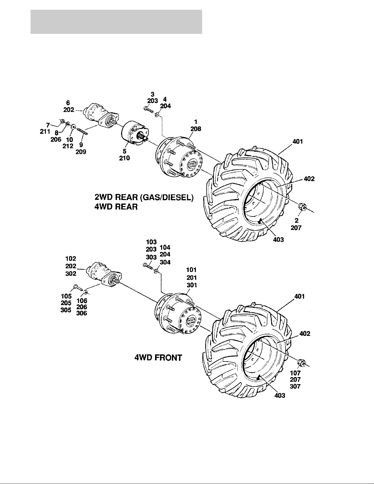
FIGURE 1-2. TIRE AND WHEEL DRIVE INSTALLATIONS
1-8 400RTS 500RTS 3120830

SECTION 1 FRAME
FIGURE 1-2. TIRE AND WHEEL DRIVE INSTALLATIONS
ITEM # PART NUMBER QTY. DESCRIPTION REV.
Ref. TIRE AND WHEEL DRIVE INSTALLATIONS
0252484 Ref. WHEEL DRIVE INSTALLATION - 2WD/2WS 3
1 2780169 2 Drive Hub Assembly (See Figure 1-6 for Breakdown)
2 3300012 18 Nut, Wheel
3 0642014 12 Bolt 5/8"-11NC x 1 3/4"
4 4762000 12 Lockwasher 5/8"
5 0920084 2 Drive Brake Assembly (See Figure 1-5 for Breakdown) (Prior to
S/N 36645)
0920110 2 Drive Brake Assembly (See Figure 1-5 for Breakdown) (S/N
36645 to Present)
6 3160158 2 Drive Motor Assembly (See Figure 1-4 for Breakdown)
7 3311801 4 Nut 1/2"-13NC
8 4761800 4 Lockwasher 1/2"
9 4300092 4 Stud 1/2"-13NC x 5 1/2"
10 4711800 4 Flatwasher 1/2" Narrow
— — — — — — — — — — —
0100011 A/R Loctite #242
0251661 Ref. WHEEL DRIVE INSTALLATION - 2WD/4WS B
101 2780195 2 Drive Hub/Brake Assembly (See Figure 1-7 for Breakdown)
102 3160158 2 Drive Motor Assembly (See Figure 1-4 for Breakdown)
103 0642014 12 Bolt 5/8"-11NC x 1 3/4"
104 4762000 12 Lockwasher 5/8"
105 0641810 4 Bolt 1/2"-13NC x 1 1/4"
106 4761800 4 Lockwasher 1/2"
107 3300012 18 Nut, Wheel
0253545 Ref. WHEEL DRIVE INSTALLATION - 4WD/2WS FRONT AND
REAR (2MPH)
0255103 Ref. WHEEL DRIVE INSTALLATION - 4WD/2WS FRONT
AND REAR (4MPH)
201 2 Drive Hub/Brake Assembly (See Figure 1-7 for Breakdown)
Options:
2780191 2 MPH
2780193 4 MPH
202 3160158 4 Drive Motor Assembly (See Figure 1-4 for Breakdown)
203 0642014 24 Bolt 5/8"-11NC x 1 7/8"
204 4762000 24 Lockwasher 5/8"
205 0641810 4 Bolt 1/2"-13NC x 1 1/4"
206 4761800 8 Lockwasher 1/2"
207 3300012 36 Nut, Wheel
208 2 Drive Hub Assembly (See Figure 1-6 for Breakdown) Options:
2780167 2 MPH
2780175 4 MPH
209 4300092 4 Stud 1/2"-13NC x 5 1/2"
2
2
3120830 400RTS 500RTS 1-9

SECTION 1 FRAME
FIGURE 1-2. TIRE AND WHEEL DRIVE INSTALLATIONS (CONTINUED)
ITEM # PART NUMBER QTY. DESCRIPTION REV.
210 0920084 2 Drive Brake Assembly (See Figure 1-5 for Breakdown) (Prior to
S/N 36645)
0920110 2 Drive Brake Assembly (See Figure 1-5 for Breakdown) (S/N
36645 to Present)
211 3311801 4 Nut 1/2"-13NC
212 4711800 4 Flatwasher 1/2"
— — — — — — — — — —
0100011 A/R Loctite #242
0251660 Ref. WHEEL DRIVE INSTALLATION - 4WD/4WS FRONT
FRONT AND REAR (2MPH)
301 2780191 4 Drive Hub/Brake Assembly (See Figure 1-7 for Breakdown)
302 3160158 4 Drive Motor Assembly (See Figure 1-4 for Breakdown)
303 0642014 24 Bolt 5/8" - 11NC x 1 3/4"
304 4762000 24 Lockwasher 5/8"
305 0641810 8 Bolt 1/2"-13NC x 1 1/4"
306 4761800 8 Lockwasher 1/2"
307 3300012 36 Nut, Wheel
0253089 Ref. TIRE AND WHEEL INSTALLATION - OPTIONAL FOAM FILLED
12 x 16.5
Ref. TIRE AND WHEEL INSTALLATION - OPTIONAL FOAM FILLED
OPTIONS:
0255660 Ref. FOAM FILLED 31 x 15.50 x 15 - OTR TRITAN (Prior to S/N
115825)
0272826 Ref. FOAM FILLED 31 x 15.50 x 15 - OTR NHS (S/N 115825 to
Present)
Ref. Note: Assemblies may require ballast/foam filling to
manufacturer’s specifications prior to installing on a
machine. Refer to Operation & Safety or Service &
Maintenance Manuals. Purchase individual tire and/or rim
only if able to foam fill tire & wheel assembly, otherwise,
purchase complete assembly.
B
—
—
—
A
401 2 Tire and Wheel Assembly - Left Side Options: —
0253088 12 x 16.5
Use 0273414 31 x 15.50 x 15 - OTR Tritan (was p/n 0255661)
0273414 31 x 15.50 x 15 - OTR NHS
2 Tire and Wheel Assembly - Right Side Options: —
0253087 12 x 16.5
Use 0273415 31 x 15.50 x 15 - OTR Tritan (was p/n 0255662)
0273415 31 x 15.50 x 15 - OTR NHS
402 to 404 Not Used
1-10 400RTS 500RTS 3120830

SECTION 1 FRAME
FIGURE 1-2. TIRE AND WHEEL DRIVE INSTALLATIONS (CONTINUED)
ITEM # PART NUMBER QTY. DESCRIPTION REV.
3120830 400RTS 500RTS 1-11
SECTION 1 FRAME
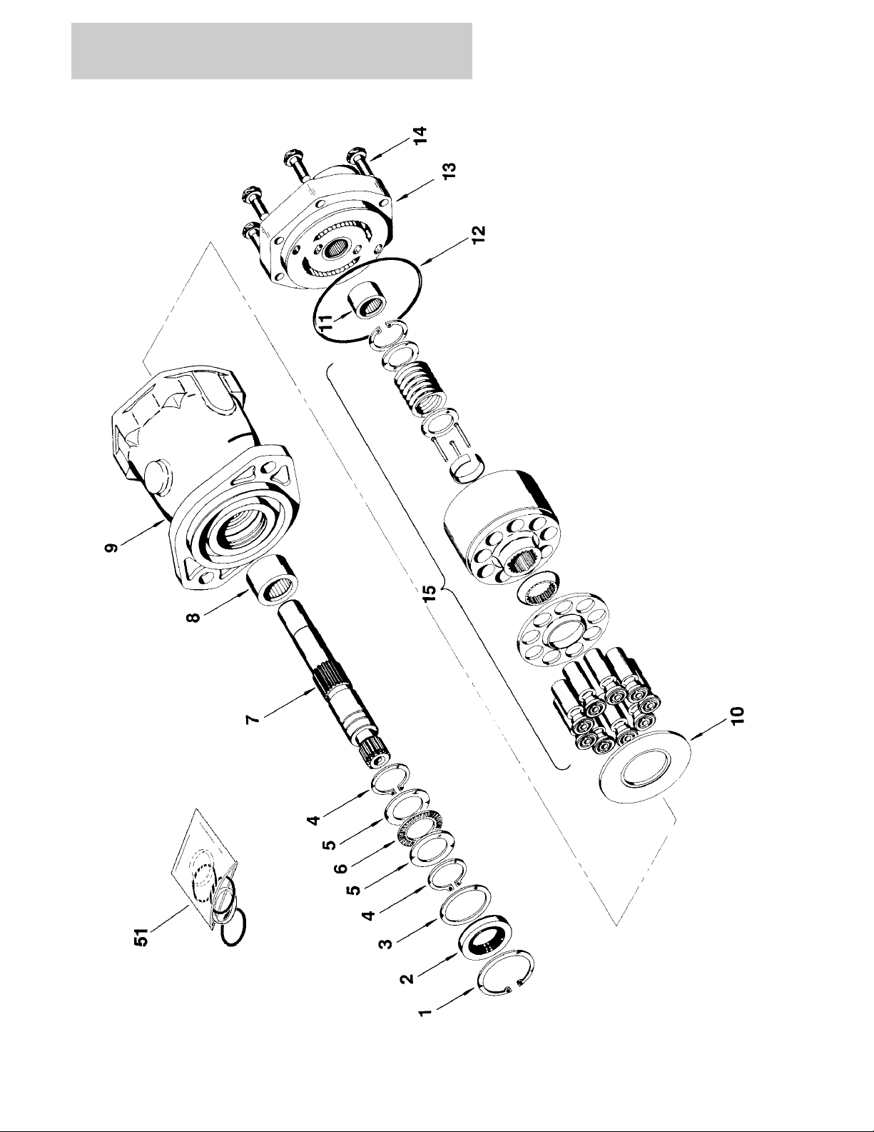
FIGURE 1-3. DRIVE MOTOR ASSEMBLY
1-12 400RTS 500RTS 3120830

SECTION 1 FRAME
FIGURE 1-3. DRIVE MOTOR ASSEMBLY
ITEM # PART NUMBER QTY. DESCRIPTION REV.
Ref. DRIVE MOTOR ASSEMBLY
3160158 Ref. DRIVE MOTOR ASSEMBLY (STANDARD PARTS)
1 Use Item 51 1 Ring, Retaining
2 Use Item 51 1 Seal, Shaft
3 7004906 1 Washer
4 Use Item 51 2 Ring, Retaining
5 7004907 2 Race, Thrust
6 7004908 1 Bearing, Thrust
7 7007874 1 Shaft, Splined
8 7004910 1 Bearing
9 7007875 1 Housing Assembly (Includes Item 8)
10 7007876 1 Insert, Camplate
11 7004917 1 Bearing
12 Use Item 51 1 O-Ring
13 7007878 1 Back Plate Assembly (Includes Item 11)
14 7007879 6 Bolt
15 7007880 1 Rotating Kit Assembly (Sold As An Assembly Only)
— — — — — — — — — —
51 2900714 1 Seal Kit (Includes Items 1,2,4 and 12)
3120830 400RTS 500RTS 1-13
SECTION 1 FRAME
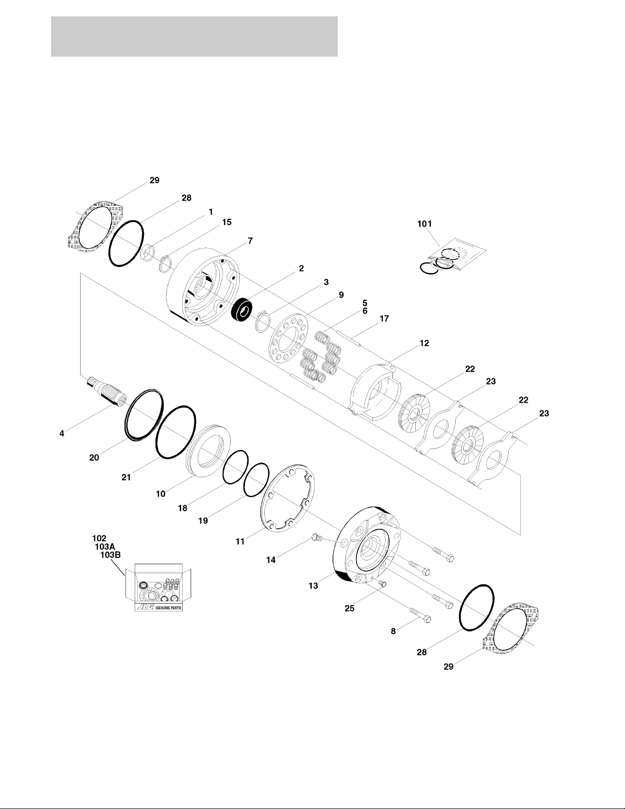
FIGURE 1-4. DRIVE BRAKE ASSEMBLY
1-14 400RTS 500RTS 3120830

SECTION 1 FRAME
FIGURE 1-4. DRIVE BRAKE ASSEMBLY
ITEM # PART NUMBER QTY. DESCRIPTION REV.
Ref. DRIVE BRAKE ASSEMBLIES
0920084 Ref. MICO - (ORIGINAL EQUIPMENT) (MACHINES BUILT PRIOR
TO S/N 36645)
0920110 Ref. MICO - (SERVICE REPLACEMENT) (MACHINES BUILT S/N
36645 TO PRESENT)
Ref. Note: Original Equipment Brake may have been replaced with
Service Replacement Brake. Identify the brake by the serial
number plate before ordering parts.
1 See Note 1 Seal, Oil (Note: Use Item 101 & 102)
2 Use Item 102 1 Bearing
3 7007977 1 Ring, Retaining
4 7011712 1 Shaft
5 6 Spring Options:
7007979 Spring (Inner) - Prior to S/N 36645 (Use with p/n 0920084)
7007970 Spring (Red) - S/N 36645 to Present (Use with p/n 0920110)
6 A/R Spring Options:
7007980 6 Spring (Outer) - Prior to S/N 36645 (Use with p/n 0920084)
7018602 3 Spring (Blue) - S/N 36645 to Present (Use with p/n 0920110)
7 1 Housing Options:
7011713 Prior to S/N 36645 (Use with p/n 0920084)
7018605 S/N 36645 to Present (Use with p/n 0920110)
8 4 Bolt, Washer Head Options:
7007985 Prior to S/N 36645 (Use with p/n 0920084)
7018607 S/N 36645 to Present (Use with p/n 0920110)
9 1 Guide, Spring Options:
7011717 Prior to S/N 36645 (Use with p/n 0920084)
7018606 S/N 36645 to Present (Use with p/n 0920110)
10 1 Piston Options:
7007923 Prior to S/N 36645 (Use with p/n 0920084)
7018603 S/N 36645 to Present (Use with p/n 0920110)
11 See Note 1 Seal, Case (Note: Use Item 101,102, 103A & 103B)
12 Use Item 103B 1 Plate, Return
7011715 2 Separator Assembly
7011714 4 Pin
7007983 2 Separator
13 7007986 1 Cover
14 7007914 1 Screw, Bleeder
15 7011716 1 Ring, Retainer
16 Not Used
17 7007987 2 Pin, Dowel
18 Use Item 101 1 Ring, Back-up
19 Use Item 101 1 O-Ring
20 Use Item 101 1 Ring, Back-up
21 Use Item 101 1 O-Ring
22 See Note 2 Rotor (Note: Use Item 103A & 103B)
23 See Note 2 Stator (Note: Use Item 103A & 103B)
24 Not Used
25 7007924 1 Plug, Pipe
26 Not Used
—
2
3120830 400RTS 500RTS 1-15

SECTION 1 FRAME
FIGURE 1-4. DRIVE BRAKE ASSEMBLY (CONTINUED)
ITEM # PART NUMBER QTY. DESCRIPTION REV.
27 Not Used
28 See Note 2 O-Ring (Note: Use Item 101,102, 103A & 103B)
29 7007933 2 Gasket
— — — — — — — — — —
101 2900766 1 Seal Kit (Includes Items 1,11,18,19,20,21,28 and 29)
102 2900768 1 Bearing Kit (Includes Items 1,2,11,28 and 29)
103 1 Lining Kit Options:
103A 2900767 Lining Kit (Includes Items 58, 11, 22,23, 28 and 29) (Prior to
S/N 36645 (Use with p/n 0920084)
103B 7018608 Lining Kit (Includes Items 58, 11, 12, 22,23, 28 and 29) (S/N
36645 to Present (Use with p/n 0920110)
1-16 400RTS 500RTS 3120830

SECTION 1 FRAME
FIGURE 1-4. DRIVE BRAKE ASSEMBLY (CONTINUED)
ITEM # PART NUMBER QTY. DESCRIPTION REV.
3120830 400RTS 500RTS 1-17
SECTION 1 FRAME
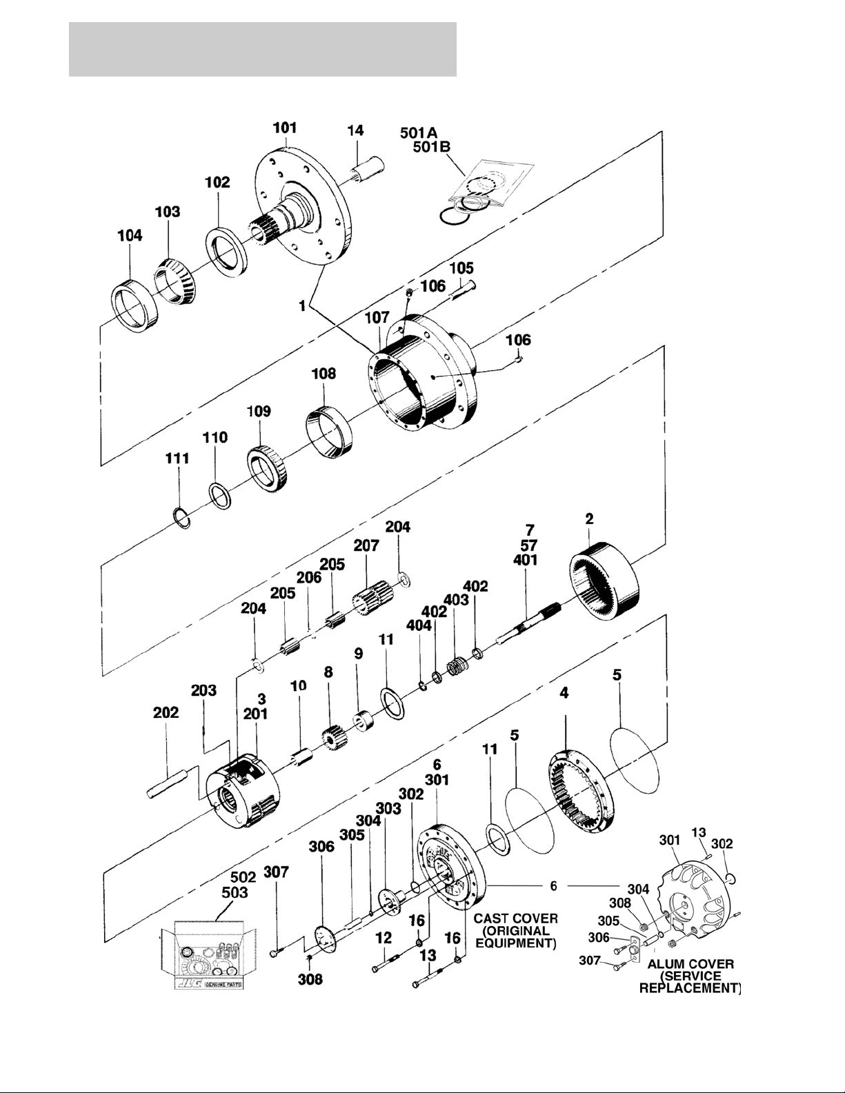
FIGURE 1-5. DRIVE HUB ASSEMBLIES
1-18 400RTS 500RTS 3120830

SECTION 1 FRAME
FIGURE 1-5. DRIVE HUB ASSEMBLIES
ITEM # PART NUMBER QTY. DESCRIPTION REV.
Ref. DRIVE HUB ASSEMBLIES
2780169 Ref. DRIVE HUB ASSEMBLY -2WD/2WS GAS/DIESEL
(2MPH)
2780167 Ref. DRIVE HUB ASSEMBLY - 4WD/2WS REAR DRIVE
ONLY (2MPH)
1 1 Hub-Spindle Sub Assembly (See Items 101-111 for Breakdown)
2 7000246 1 Gear, Internal
3 7000247 1 Carrier Assembly (See Items 201-207 for Breakdown)
4 7000248 1 Gear, Ring
5 7000230 2 O-Ring
6 7001989 1 Cover Assembly (Includes Items 301-308)
7 1 Input Shaft Assembly (See Items 401-404 for Breakdown)
Options:
7000250 Input Shaft Assembly (2WD Machines)
7007650 Input Shaft Assembly (4WD Machines)
8 1 Gear, Input Options:
7000251 Gear, Input (2WD)
7007652 Gear, Input (4WD)
9 1 Spacer, Thrust Options:
7000252 Spacer, Thrust (2WD Machines)
7007653 Spacer, Thrust (4WD Machines)
10 1 Spacer, Thrust Options:
Not Required Spacer, Thrust (2WD Machines)
7007654 Spacer, Thrust (4WD Machines)
11 7000253 2 Washer, Thrust
12 7000217 12 Bolt
13 7000214 4 Bolt, Shoulder
14 7000206 1 Coupling
15 Not Used
16 7007603 16 Flatwasher
B
B
Ref. HUB - SPINDLE SUB-ASSEMBLY
101 7001997 1 Spindle
102 7001998 1 Seal
103 Use Item 502 1 Cone, Bearing
104 Use Item 502 1 Cup, Bearing
105 7007697 9 Bolt, Wheel
106 7000242 2 Plug, Pipe
107 7007601 1 Hub
108 7000257 1 Cup, Bearing
109 7000258 1 Cone, Bearing
110 7000232 1 Spacer
111 7000229 1 Ring, Retaining
3120830 400RTS 500RTS 1-19

SECTION 1 FRAME
FIGURE 1-5. DRIVE HUB ASSEMBLIES (CONTINUED)
ITEM # PART NUMBER QTY. DESCRIPTION REV.
7000247 Ref. CARRIER ASSEMBLY
201 7001931 1 Carrier
202 7001911 3 Shaft
203 7001913 3 Pin, Roll
204 7001985 6 Washer, Thrust
205 7001909 96 Roller, Needle
206 7000263 3 Spacer
207 7001912 3 Gear, Cluster (2MPH)
Ref. COVER ASSEMBLY
See Kit Options Ref. Cast Cover (Original Equipment)
See Kit Options Ref. Aluminum Cover (Service Replacement)
301 1 Cover Options:
Use 70001111 Cast Cover (Original Equipment)
(was p/n 7000226)
Use 70001349 Aluminum Cover (Service Replacement)
(was p/n 7017091)
302 1 O-Ring Options:
Use 70001111 Cast Cover (Original Equipment)
Use 70001349 Aluminum Cover (Service Replacement)
(was p/n 7017070)
303 1 Cap, Cover
Use 70001111 Cast Cover (Original Equipment)
Not Required Aluminum Cover (Service Replacement)
304 1 O-Ring Options:
Use 70001111 Cast Cover (Original Equipment)
Use 70001349 Aluminum Cover (Service Replacement)
(was p/n 7017095)
305 1 Rod, Disconnect Options:
Use 70001111 Cast Cover (Original Equipment)
Use 70001349 Aluminum Cover (Service Replacement)
(was p/n 7017092)
306 1 Cap, Disconnect
Use 70001111 Cast Cover (Original Equipment)
Use 70001349 Aluminum Cover (Service Replacement)
(was p/n 7017093)
307 A/R Bolt Options:
Use 70001111 4 Cast Cover (Original Equipment)
(was p/n 7000220)
Use 70001349 2 Aluminum Cover (Service Replacement)
(was p/n 7000216)
308 A/R Plug, Pipe Options:
Use 70001111 1 Cast Cover (Original Equipment)
(was p/n 7000243)
Use 70001349 2 Aluminum Cover (Service Replacement)
(was p/n 7017094)
— — — — — — — — — — —
1-20 400RTS 500RTS 3120830

SECTION 1 FRAME
FIGURE 1-5. DRIVE HUB ASSEMBLIES (CONTINUED)
ITEM # PART NUMBER QTY. DESCRIPTION REV.
1 Cover Kit Options:
Ref. Note: Kit Replaces Items 5, 11 (Spacer), 12, 13 (Dowel
Pins) & 301-308.
Use 70001111 Cast Cover (Original Equipment)
(was p/n 7001989 & p/n 7017099)
Use 70001349 Aluminum Cover (Service Replacement)
(was p/n 7017090)
7000250 Ref. INPUT SHAFT ASSEMBLY (2WD MACHINES)
7007650 Ref. INPUT SHAFT ASSEMBLY (4WD MACHINES)
401 7000260 1 Shaft (2WD Machines)
7007651 1 Shaft (4WD Machines)
402 7000263 2 Spacer
403 7000262 1 Spring
404 7000261 1 Ring, Retaining
— — — — — — — — — —
501 1 Seal Kit Options:
501A 7017063 1 Seal Kit (Includes Items 5, 11, 102, 111, 302 and 304)
501B 2900034 1 Seal Kit (Includes Items 5, 102 110 and 111)
502 7010429 1 Bearing Kit (Includes Items 103 and 104)
503 2900137 Disconnect and Seal Kit (Includes Items 5, 102, 110, 110 and
302 - 307
3120830 400RTS 500RTS 1-21
SECTION 1 FRAME
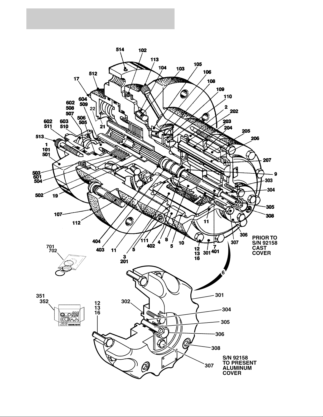
FIGURE 1-6. DRIVE HUB/BRAKE ASSEMBLIES
1-22 400RTS 500RTS 3120830

SECTION 1 FRAME
FIGURE 1-6. DRIVE HUB/BRAKE ASSEMBLIES
ITEM # PART NUMBER QTY. DESCRIPTION REV.
Ref. DRIVE HUB/BRAKE ASSEMBLY OPTIONS:
2780195 Ref. 2WD/4WS GAS/DIESEL MACHINES (2MPH) —
2780191 Ref. 4WD GAS/DIESEL MACHINES (2MPH) —
2780193 Ref. 4WD/2WS GAS/DIESEL MACHINES (4MPH) —
1 See Note 1 Hub/Spindle/Brake Assembly (Note: Not sold as a complete
assembly) (See Items 101-113 for Breakdown)
2 7007691 1 Gear, Internal
3 1 Carrier Assembly Options (See Items 201-207 for Breakdown):
Not Available 2WD/4WS Machines
7000247 4WD with 2MPH Machines
See Note 4WD with 4MPH Machines (Note: Purchase 7000247 & install
(3) 7007643 Cluster Gears to make this carrier assembly)
4 7000248 1 Gear, Internal
5 See Note 2 O-Ring (Note: Use Items 351 & 352)
6 1 Cover Assembly
(See Items 301-308 for Breakdown)
7 1 In put Shaft Assembly Options
(See Items 401-404 for Breakdown):
7007650 4WD Machines
7000250 2WD/4WS Machines
8 1 Gear, Input Options:
7007652 4WD Machines
7000251 2WD/4WS Machines
9 1 Spacer, Input Options:
7007653 4WD Machines
7000252 2WD/4WS Machines
10 1 Spacer, Input Options:
7007654 4WD Machines
Not Required 2WD/4WS Machines
11 7000253 2 Washer, Thrust
7017096 1 Spacer (S/N 92158 to Present Only)
12 12 Bolt Options:
7000217 Prior to S/N 92158
7017067 S/N 92158 to Present
13 4 Hardware Options:
7000214 Bolt Used Prior to S/N 92158
7017080 Dowel Pin Used S/N 92158 to Present
14 to 15 Not Used
16 7007603 16 Flatwasher
17 7007692 1 Gasket
18 Not Used
19 7010470 1 Coupling
20 Not Used
21 7010459 1 Ring, Retainer
22 7001922 1 Washer, Thrust
3120830 400RTS 500RTS 1-23

SECTION 1 FRAME
FIGURE 1-6. DRIVE HUB/BRAKE ASSEMBLIES (CONTINUED)
ITEM # PART NUMBER QTY. DESCRIPTION REV.
Ref. HUB/SPINDLE/BRAKE SUB-ASSEMBLY
101 1 Brake Assembly Options:
7010473 2WD/4WS Machines and 4WD Machines with I.D. Plate
(Stamped July 1992 or Later (See Items 601-604 for
Breakdown)
7010469 4WD Machines with I.D. Plate Stamped Prior to July 1992
(See Items 501-514 for Breakdown)
102 Use Item 701 1 Seal, Lip
103 7007683 1 Cup, Bearing
104 7007684 1 Cone, Bearing
105 7007685 1 Cup, Bearing
106 7007686 1 Cone, Bearing
107 7007687 1 Housing
108 7007688 1 Flatwasher, Tanged
109 7007689 1 Flatwasher, Tanged
110 7007690 1 Nut, Bearing
111 7000242 2 Plug, Pipe 1/4" NPT
112 7000241 9 Stud, Wheel
113 7007617 2 Plug, Pipe 3/8" NPT (Magnetic)
7000247 Ref. CARRIER ASSEMBLY - 4WD(2MPH) MACHINES
NPN Ref. CARRIER ASSEMBLY - 4WD(4MPH) MACHINES
NPN Ref. CARRIER ASSEMBLY - 2WD/4WS MACHINES
201 7001931 1 Carrier
202 7001985 6 Washer, Thrust - Tanged
203 7001909 96 Bearing, Needle
204 7000263 3 Spacer, Thrust
205 7001911 3 Shaft, Planet
206 3 Gear, Cluster Options:
7001912 4WD with 2MPH Hub and 2WD/4WS
7007643 4WD with 4MPH Hub
207 3 Rollpin Options:
7001913 4WD Machines
7010474 2WD/4WS Machines
Ref. COVER ASSEMBLY
See Kit Options Ref. Cast Cover (Original Equipment)
See Kit Options Ref. Aluminum Cover (Service Replacement)
301 1 Cover Options:
Use 70001111 Cast Cover (Original Equipment)
(was p/n 7000226)
Use 70001349 Aluminum Cover (Service Replacement)
(was p/n 7017091)
302 1 O-Ring Options:
Use 70001111 Cast Cover (Original Equipment)
Use 70001349 Aluminum Cover (Service Replacement)
(was p/n 7017070)
1-24 400RTS 500RTS 3120830

SECTION 1 FRAME
FIGURE 1-6. DRIVE HUB/BRAKE ASSEMBLIES (CONTINUED)
ITEM # PART NUMBER QTY. DESCRIPTION REV.
303 1 Cap, Cover
Use 70001111 Cast Cover (Original Equipment)
Not Required Aluminum Cover (Service Replacement)
304 1 O-Ring Options:
Use 70001111 Cast Cover (Original Equipment)
Use 70001349 Aluminum Cover (Service Replacement)
(was p/n 7017095)
305 1 Rod, Disconnect Options:
Use 70001111 Cast Cover (Original Equipment)
Use 70001349 Aluminum Cover (Service Replacement)
(was p/n 7017092)
306 1 Cap, Disconnect
Use 70001111 Cast Cover (Original Equipment)
Use 70001349 Aluminum Cover (Service Replacement)
(was p/n 7017093)
307 A/R Bolt Options:
Use 70001111 4 Cast Cover (Original Equipment)
(was p/n 7000220)
Use 70001349 2 Aluminum Cover (Service Replacement)
(was p/n 7000216)
308 A/R Plug, Pipe Options:
Use 70001111 1 Cast Cover (Original Equipment)
(was p/n 7000243)
Use 70001349 2 Aluminum Cover (Service Replacement)
(was p/n 7017094)
309 to 350 Not Used
— — — — — — — — — — —
1 Cover Kit Options:
Ref. Note: Kit Replaces Items 5, 11 (Spacer), 12, 13 (Dowel
Pins) & 301-308.
351 Use 70001111 Cast Cover (Original Equipment)
(was p/n 7001989 & p/n 7017099)
352 Use 70001349 Aluminum Cover (Service Replacement)
(was p/n 7017090)
7007650 Ref. INPUT SHAFT ASSEMBLY - 4WD MACHINES
7000250 Ref. INPUT SHAFT ASSEMBLY - 2WD/4WS MACHINES
401 1 Shaft Options:
7007651 4WD Machines
7000260 2WD/4WS Machines
402 7000261 1 Ring, Retaining
403 7000262 1 Spring
404 7000263 2 Spacer, Thrust
7010469 Ref. BRAKE ASSEMBLY - 4WD MACHINES WITH I.D. PLATE
STAMPED JUNE 1992 OR EARLIER
501 7014100 1 Spindle
502 7014101 1 Spacer
503 7014102 7 Disc, Stationary
3120830 400RTS 500RTS 1-25

SECTION 1 FRAME
FIGURE 1-6. DRIVE HUB/BRAKE ASSEMBLIES (CONTINUED)
ITEM # PART NUMBER QTY. DESCRIPTION REV.
504 7014103 6 Disc, Rotating
505 Use Item 702 1 Ring, Back-up
506 Use Item 702 1 O-Ring
507 Use Item 702 1 Ring, Back-up Ring
508 Use Item 702 1 O-Ring
509 7014108 1 Piston
510 7014109 6 Spring
7014110 2 Spring
511 Use Item 702 1 O-Ring
512 7014112 1 Cover
513 Not Available 8 Bolt, Socket Head 3/8"-16NC x 1 1/4"
514 7014113 1 Expander
7010473 Ref. BRAKE ASSEMBLY - 2WD/4WS MACHINES AND 4WD
MACHINES WITH I.D. PLATE STAMPED JULY 1992 OR
LATER
601 7010475 1 Brake Lining Kit
602 7010476 1 Brake O-Ring Kit
603 7010477 1 Brake Spring Repair Kit
604 7010478 1 Brake Piston Repair Kit
— — — — — — — — — —
Ref Kit Options:
701 Use 70001940 1 Seal Kit - Hub (Includes Items 5,17,102,306 and 307)
(was p/n 2900754)
702 2900816 1 Brake O-Ring Kit (Includes Items 505-508 and 511)
1-26 400RTS 500RTS 3120830

SECTION 1 FRAME
FIGURE 1-6. DRIVE HUB/BRAKE ASSEMBLIES (CONTINUED)
ITEM # PART NUMBER QTY. DESCRIPTION REV.
3120830 400RTS 500RTS 1-27

SECTION 1 FRAME
FIGURE 1-7. FRAME MOUNTED COMPONENTS INSTALLATION
1-28 400RTS 500RTS 3120830

SECTION 1 FRAME
FIGURE 1-7. FRAME MOUNTED COMPONENTS INSTALLATION
ITEM # PART NUMBER QTY. DESCRIPTION REV.
Ref. FRAME MOUNTED COMPONENTS INSTALLATION
0253517 Ref. LIMIT SWITCH INSTALLATION - 500RTS (Prior to S/N 111178) 5
0272935 Ref. LIMIT SWITCH INSTALLATION - 500RTS (S/N 111178 to S/N
112737)
0272969 Ref. LIMIT SWITCH INSTALLATION - 500RTS (S/N 112737 to Pres-
ent)
0254058 Ref. LIMIT SWITCH INSTALLATION - 400RTS WITH STANDARD
TIRES (Prior to S/N 111178)
0254059 Ref. LIMIT SWITCH INSTALLATION - 400RTS WITH 31 x 15.5-15
(Prior to S/N 111178)
0272936 Ref. LIMIT SWITCH INSTALLATION - 400RTS WITH 31 x 15.5-15 (S/
N 111178 to Present)
1 1 Bracket, Mounting Options:
500RTS Options:
0901902 Prior to S/N 111178
4846822 S/N 111178 to Present
Not Required 400RTS With Standard Tires
400RTS With 31 x 15.5-15 Tires Options:
0901966 Prior to S/N 111178
4846822 S/N 111178 to Present
2 4360300 A/R Switch, Limit
3 4460049 A/R Connector, Strain Relief
4 2 Washer Options:
4751500 Flatwasher 5/16" (Prior to S/N 111178)
4891600 Washer, Hardened 3/8" (S/N 111178 to Present)
Not Required 400RTS With Standard Tires
5 2 Lockwasher Options:
4761500 Lockwasher 5/16" (Prior to S/N 111178)
Not Required 400RTS With Standard Tires
6 2 Nut Options:
3311501 Nut 5/16"-18NC
Not Required 400RTS With Standard Tires
7 3440413 A/R Rollpin 1/8" x 13/16" (Prior to S/N 112737)
8 1100083 1 Cam (Hi-Drive Cutout) (Prior to S/N 112737)
9 4300038 2 Stud (Welded Part)
10 3911032 A/R Bolt, Socket Head #10-24NC x 2"
11 4751000 A/R Flatwasher #10
12 4761000 A/R Lockwasher #10 (Prior to S/N 111178)
13 3311005 A/R Locknut #10-24NC
14 0901917 1 Bracket (Prior to S/N 112737)
15 4751600 A/R Flatwasher 3/8"
16 3951503 2 Setscrew 5/16"-18NC x 3/4" (Prior to S/N 112737)
17 1100137 1 Cam, Limit Switch (S/N 111178 to Present)
18 0100011 A/R Loctite #242 (Not Shown) (S/N 111178 to Present)
19 0641626 2 Bolt 3/8 - 16NC x 3 1/4” (S/N 111178 to Present)
20 3574274 1 Plate, Clamp (S/N 111178 to Present)
21 1060965 1 Cable - 16/2 (92ft/28.1m) (Not Shown) (S/N 1075516 to Pres-
ent)
1
1
B
A
1
3120830 400RTS 500RTS 1-29

SECTION 1 FRAME
FIGURE 1-7. FRAME MOUNTED COMPONENTS INSTALLATION (CONTINUED)
ITEM # PART NUMBER QTY. DESCRIPTION REV.
22 1060966 1 Cable - 16/2 (85ft/25.9m) (Not Shown) (S/N 1075516 to S/N
109670)
0253237 Ref. LADDER INSTALLATION - 500RTS WITHOUT DUAL
EXTENDABLE PLATFORMS
0253238 Ref. LADDER INSTALLATION - 500RTS WITH DUAL
EXTENDABLE PLATFORMS
0271332 Ref. LADDER INSTALLATION - 500RTS WITH MEGADECK PLAT-
FORMS (S/N 95337 TO PRESENT)
0253933 Ref. LADDER INSTALLATION - 400RTS WITHOUT DUAL
EXTENDABLE PLATFORMS (PRIOR TO S/N 70978)
0253934 Ref. LADDER INSTALLATION - 400RTS WITH DUAL
EXTENDABLE PLATFORMS (PRIOR TO S/N 70978)
0254302 Ref. LADDER INSTALLATION - 400RTS WITHOUT DUAL
EXTENDABLE PLATFORMS
101 2 Ladder Weldment - Side Options:
4844249 500RTS
4846407 500RTS - With Megadeck Platform
4844490 400RTS
102 1 Ladder Weldment - Rear
4844250 500RTS Without Dual Extendable Platform
(Prior to S/N 65789)
4846051 500RTS Without Dual Extendable Platform
(S/N 65789 to Present)
Not Required 500RTS With Dual Extendable Platform
Not Required 500RTS - With Megadeck Platform
4844491 400RTS Without Dual Extendable Platform
(Prior to S/N 65789)
4846055 400RTS Without Dual Extendable Platform
(S/N 65789 to Present)
Not Required 400RTS With Dual Extendable Platform
103 0362171 1 Bar
104 0181678 1 Angle, Mounting
105 0181679 1 Angle, Mounting
106 0641612 A/R Bolt 3/8"-16NC x 1 1/2"
107 4751600 A/R Flatwasher 3/8"
108 4761600 A/R Lockwasher 3/8
Not Required 500RTS - With Megadeck Platform
109 A/R Nut Options:
3311601 Nut 3/8"-16NC (With Dual Extendable Platform)
3311605 Locknut 3/8-16NC (Without Dual Extendable Platform/Mega-
deck Platform)
110 0641524 3 Bolt 5/16"-18NC x 3"
111 4751500 8 Flatwasher 5/16"
112 4761500 4 Lockwasher 5/16"
Not Required 500RTS - With Megadeck Platform
113 4 Nut Options:
3311501 Nut 5/16”-18NC (With Dual Extendable Platform)
3311505 Locknut 5/16”-18NC (Without Dual Extendable Platform/
Megadeck Platform)
5
3
2
4
2
2
1-30 400RTS 500RTS 3120830

SECTION 1 FRAME
FIGURE 1-7. FRAME MOUNTED COMPONENTS INSTALLATION (CONTINUED)
ITEM # PART NUMBER QTY. DESCRIPTION REV.
114 0641510 1 Bolt 5/16"-18NC x 1 1/4"
115 to 116 Not Used
117 3520071 A/R Cap
0253446 Ref. OPTIONAL TRAVEL ALARM INSTALLATION (STANDARD
PARTS WHEN EQUIPPED) (PRIOR TO S/N 71538)
0253727 Ref. OPTIONAL DESCENT ALARM INSTALLATION
(STANDARD PARTS WHEN EQUIPPED) (PRIOR TO
S/N 112737)
0273055 Ref. OPTIONAL DESCENT ALARM INSTALLATION
(STANDARD PARTS WHEN EQUIPPED) (S/N 112737 TO
PRESENT)
0253728 Ref. OPTIONAL MOTION ALARM INSTALLATION (STANDARD
PARTS WHEN EQUIPPED) (PRIOR TO S/N 112737)
0273056 Ref. OPTIONAL MOTION ALARM INSTALLATION (STANDARD
PARTS WHEN EQUIPPED) (S/N 112737 TO PRESENT)
See Note Ref. CE Spec (Note: For CE Spec Machines with Overload Refer to
JLG Supplement p/n 3124288 for Components.)
201 0140032 1 Alarm (Prior to S/N 112737)
202 4300038 2 Stud (Welded on Part) (Prior to S/N 112737)
203 4761500 2 Lockwasher 5/16" (Prior to S/N 112737)
204 3311501 2 Nut 5/16"-18NC (Prior to S/N 112737)
205 4751500 2 Flatwasher 5/16" (Prior to S/N 112737)
— — — — — — — — — —
3990010 A/R Diode - 6 Amp (Not Shown - Located at Ground Control)
3740049 1 Relay (Not Shown - Located at Ground Control)
1540002 1 Capacitor (Not Shown - Located at Ground Control) (S/N
112737 to Present)
A
B
1
A
1
0273057 Ref. OPTIONAL HORN INSTALLATION (STANDARD PARTS WHEN
EQUIPPED)
251 0140044 1 Alarm
252 4300032 2 Stud (Welded on Part)
253 4761400 2 Lockwasher 1/4"
254 3311401 2 Nut 1/4"-20NC
255 4751400 2 Flatwasher 1/4"
— — — — — — — — — —
4460539 1 Terminal, Male - 3 Position
4460465 2 Socket, Female
4460466 1 Terminal, Sealing Plug
0253448/0253449 Ref. AXLE COVERS INSTALLATION (2WS) (STANDARD PARTS) —
301 2 Plate, Cover Options:
4844186 Gas Machines
3536092 Diesel Machines
302 0641510 8 Bolt 5/16"-18NC x 1 1/4"
303 4751500 16 Flatwasher 5/16"
304 4761500 8 Lockwasher 5/16"
305 3311501 8 Nut 5/16"-18NC
1
3120830 400RTS 500RTS 1-31

SECTION 1 FRAME
FIGURE 1-7. FRAME MOUNTED COMPONENTS INSTALLATION (CONTINUED)
ITEM # PART NUMBER QTY. DESCRIPTION REV.
0253453 Ref. CIRCULAR LEVEL INSTALLATION —
401 2420038 1 Level, Circular
402 3910610 3 Screw #6-32NC x 5/8"
403 4770600 3 Starwasher #6
1-32 400RTS 500RTS 3120830

SECTION 1 FRAME
FIGURE 1-7. FRAME MOUNTED COMPONENTS INSTALLATION (CONTINUED)
ITEM # PART NUMBER QTY. DESCRIPTION REV.
3120830 400RTS 500RTS 1-33

SECTION 1 FRAME
FIGURE 1-8. FRAME MOUNTED OPTIONS INSTALLATION
1-34 400RTS 500RTS 3120830

SECTION 1 FRAME
FIGURE 1-8. FRAME MOUNTED OPTIONS INSTALLATION
ITEM # PART NUMBER QTY. DESCRIPTION REV.
0253678 Ref. LEVELING JACKS INSTALLATION (OPTIONAL ON
400RTS/STANDARD ON 500RTS) (PRIOR TO S/N 107516)
0271314 Ref. LEVELING JACKS INSTALLATION (500RTS) (S/N 107516 TO
PRESENT)
1 4844346 2 Jack Cylinder Weldment
2 4 Jack Cylinder Assembly Options (See Section 5 for Breakdown):
Use 1684216 Prior to S/N 104832 (was p/n 1682720)
1684216 S/N 104832 to S/N 107516
Use 1684217 S/N 107516 to Present (was p/n 1683966)
3 16 Bolt Options:
0641828 Bolt 1/2-13NC x 3 1/2 (Prior to S/N 103576)
0641830 Bolt 1/2-13NC x 3 3/4 (S/N 103576 to Present)
4Not Used
5 4761800 16 Lockwasher 1/2"
6 0642014 16 Bolt 5/8"-11NC x 1 3/4"
7 4712000 32 Flatwasher 5/8" Narrow
8 4762000 16 Lockwasher 5/8" (Prior to S/N 64796)
9 3312005 16 Nut 5/8"-11NC
10 4420052 8.5 ft. Tape, Safety
11 8 Switch, Limit Options:
Use 4360548 Prior to S/N 109670 (was p/n 4360321)
4360548 S/N 109670 to Present
12 3911020 16 Screw, Machine #10-24NC x 1 1/4" (Prior to S/N 27385)
3930820 16 Screw #8-32 x 1 1/4" (S/N 27385 to Present)
13 3311005 16 Lock Nut #10-24NC (Prior to S/N 27385)
3310805 16 Lock Nut #8-32 (S/N 27385 to Present)
14 4751000 16 Flatwasher #10 (Prior to S/N 27385)
4750800 16 Flatwasher #8 (S/N 27385 to Present)
15 8 Connector, Strain Relief Options:
4460428 Prior to S/N 109670
4460968 S/N 109670 to Present
16 3841208 4 Rod (Prior to S/N 26251)
3841326 4 Rod (S/N 26251 to Present)
17 4160116 4 Spring
18 4740415 4 Washer, Special
19 3440420 8 Rollpin
20 4060848 4 Cover
21 0641406 16 Bolt 1/4"-20NC x 3/4"
22 4751400 16 Flatwasher 1/4"
23 4761400 16 Lockwasher 1/4"
24 1703814 4 Decal - Tie Down
25 3520082 8 Plug, Cap (Not Shown)
26 4460234 4 Pad, Adhesive (Not Shown)
27 1060971 1 Cable, 16/2 (18ft/5.5m)(Not Shown) (S/N 79847 to Present)
28 1060968 1 Cable, 16/2 (16ft/4.9m)(Not Shown) (S/N 79847 to Present)
29 1060969 2 Cable, 16/2 (10ft/3.0m)(Not Shown) (S/N 79847 to Present)
30 1060970 1 Cable, 16/2 (23ft/7.0m)(Not Shown) (S/N 79847 to Present)
15
4
3120830 400RTS 500RTS 1-35

SECTION 1 FRAME
FIGURE 1-8. FRAME MOUNTED OPTIONS INSTALLATION (CONTINUED)
ITEM # PART NUMBER QTY. DESCRIPTION REV.
0253821 Ref. HEADLIGHTS AND TAILLIGHTS INSTALLATION
(OPTIONAL)
101 2920110 2 Headlight
102 0901927 2 Bracket - Headlight
103 4300032 4 Stud (Welded on Part)
104 4761400 4 Lockwasher 1/4"
105 4751400 4 Flatwasher 1/4"
106 3311401 4 Nut 1/4"-20NC
107 2920113 2 Taillight
108 Not Used
109 0901928 2 Bracket - Taillight
110 0642012 2 Bolt 5/8"-11NC x 1 1/2"
111 4752000 2 Flatwasher 5/8"
112 4762000 2 Lockwasher 5/8"
113 3312001 2 Nut 5/8"-20NC
114 3911040 4 Screw, Machine #10-24NC x 2 1/2"
115 4771000 4 Starwasher #10
116 4751000 4 Flatwasher #10
117 3311001 4 Nut #10-24NC
118 4360329 1 Switch, Toggle (Not Shown - Located at Platform Console Box)
119 3790012 1 O-Ring (Not Shown - Located at Platform Console Box)
120 to 124 Not Used
125 1060341 30 ft./9m Cable, Electrical - 16/2
126 Not Used
127 3740049 1 Relay, Bosch (Not Shown - Located at Ground Control)
128 to 133 Not Used
134 4460051 1 Relief, Strain (Not Shown - Located at Ground Control) (S/N
106887 to Present)
135 3300048 1 Locknut (Not Shown - Located at Ground Control) (S/N 106887 to
Present)
136 0960238 1 Bushing (Not Shown - Located at Ground Control) (S/N 106887 to
Present)
3
1-36 400RTS 500RTS 3120830

SECTION 1 FRAME
FIGURE 1-8. FRAME MOUNTED OPTIONS INSTALLATION (CONTINUED)
ITEM # PART NUMBER QTY. DESCRIPTION REV.
3120830 400RTS 500RTS 1-37

SECTION 1 FRAME
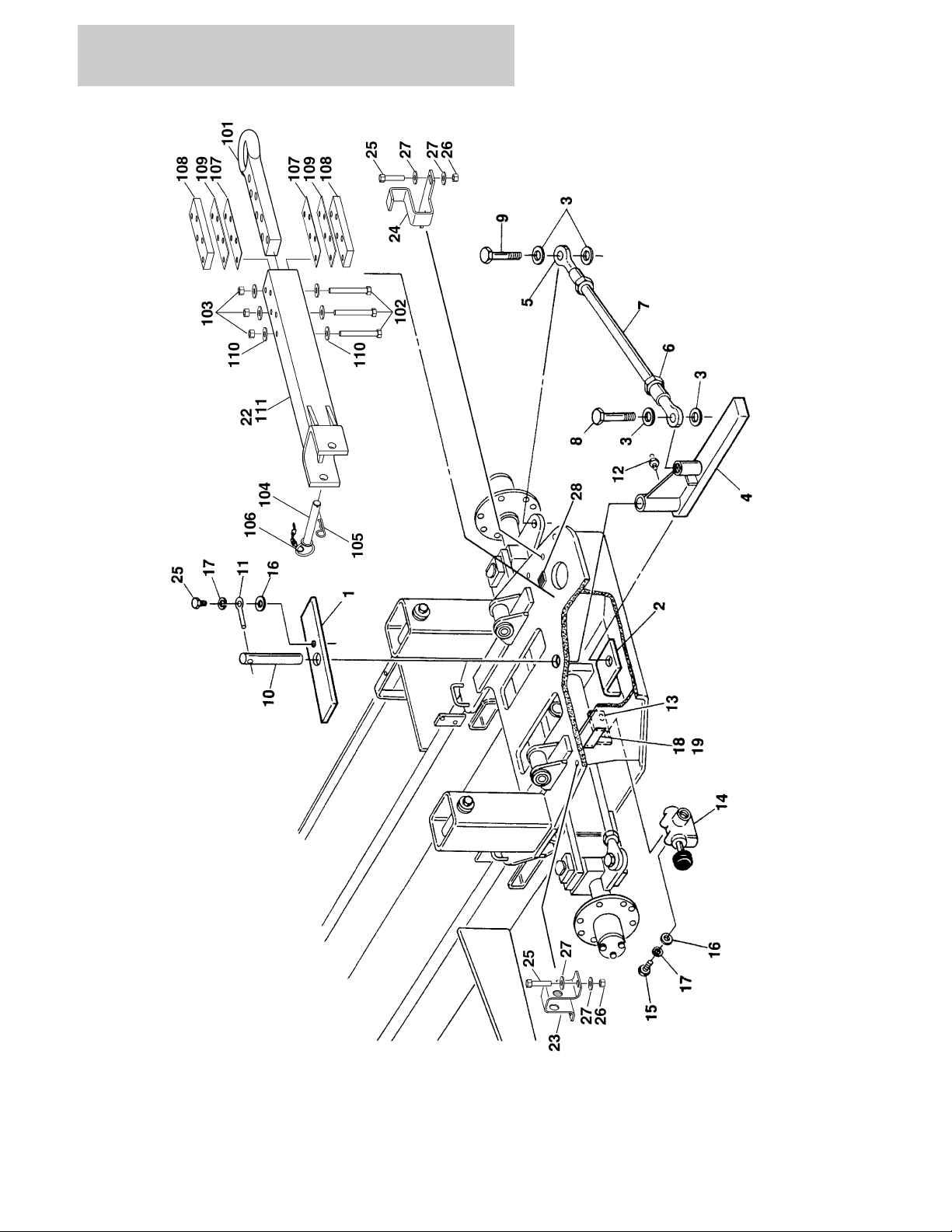
FIGURE 1-9. TOW PACKAGE INSTALLATION - BALL (OPTIONAL)
1-38 400RTS 500RTS 3120830

SECTION 1 FRAME
FIGURE 1-9. TOW PACKAGE INSTALLATION - BALL (OPTIONAL)
ITEM # PART NUMBER QTY. DESCRIPTION REV.
0253079 Ref. TOW BAR INSTALLATION E
1 0362080 1 Bar
2 3536156 1 Plate, Hitch Attach
3 4712600 4 Flatwasher 1"
4 2620037 1 Hitch, Tow
5 1660114 2 Coupling, Tie-Rod
6 3323002 2 Nut, Jam 1 1/4"-12NF
7 3841184 1 Tie-Rod
8 0642624 1 Bolt 1"-8NC x 3"
9 0642636 1 Bolt 1"-8NC x 4 1/2"
10 3422091 1 Pin
11 3841143 1 Keeper, Pin
12 2160002 1 Fitting, Grease
13 0900479 1 Bracket, Valve Mounting
14 4640261 1 Valve
15 0641507 2 Bolt 5/16"-18NC x 7/8"
16 4751500 3 Flatwasher 5/16"
17 4761500 3 Lockwasher 5/16"
18 3250872 1 Nameplate - Steer/Tow
19 3820001 4 Rivet
20 3420292 2 Pin, Quick Release
21 1260017 2 Chain
22 3536157 2 Plate
23 3537973 2 Plate
24 0362126 1 Tow Bar Assembly
3420352 1 Pin, Tow
3420158 1 Hairpin
25 0641508 1 Bolt 5/16"-18NC x 1"
26 Not Used
27 3420372 1 Hairpin, Cotter
3120830 400RTS 500RTS 1-39
SECTION 1 FRAME
FIGURE 1-10. TOW PACKAGE INSTALLATION - PINTLE HOOK (OPTIONAL)
1-40 400RTS 500RTS 3120830

SECTION 1 FRAME
FIGURE 1-10. TOW PACKAGE INSTALLATION - PINTLE HOOK (OPTIONAL)
ITEM # PART NUMBER QTY. DESCRIPTION REV.
0271499 Ref. TOW BAR INSTALLATION 1
1 0362080 1 Bar
2 3536156 1 Plate, Hitch Attach
3 4712600 4 Flatwasher 1"
4 2620037 1 Hitch, Tow
5 1660114 2 Coupling, Tie-Rod
6 3323002 2 Nut, Jam 1 1/4"-12NF
7 3841184 1 Tie-Rod
8 0642624 1 Bolt 1"-8NC x 3"
9 0642636 1 Bolt 1"-8NC x 4 1/2"
10 3422091 1 Pin
11 3841143 1 Keeper, Pin
12 2160002 1 Fitting, Grease
13 0900479 1 Bracket, Valve Mounting
14 4640261 1 Valve
15 0641507 2 Bolt 5/16"-18NC x 7/8"
16 4751500 3 Flatwasher 5/16"
17 4761500 3 Lockwasher 5/16"
18 3250872 1 Nameplate - Steer/Tow
19 3820001 4 Rivet
20 0641508 1 Bolt 5/16”-18NC x 1”
21 Not Used
22 0363019 1 Tow Bar Assembly (See Items 101-111 for breakdown)
23 0902733 1 Bracket
24 0902734 1 Bracket
25 0642018 4 Bolt 5/8"-11NC x 2 1/4"
26 3312005 4 Locknut 5/8”-11NC
27 4752000 8 Flatwasher 5/8
28 3340841 1 Pad
0363019 Ref. TOW BAR ASSEMBLY B
101 0360406 1 Bar, Draw
102 0642040 5 Bolt 5/8”-11NC x 5”
103 3312005 5 Locknut 5/8”-11NC
104 3420352 1 Pin, Towing
105 3420372 1 Pin, Cotter
106 3760170 1 Ring, Split
107 4070450 2 Shim
108 4070560 2 Shim
109 4070561 2 Shim
110 4752000 10 Flatwasher 5/8
111 4846439 1 Tow Bar Weldment
3120830 400RTS 500RTS 1-41

SECTION 1 FRAME
FIGURE 1-10. TOW PACKAGE INSTALLATION - PINTLE HOOK (OPTIONAL) (CONTINUED)
ITEM # PART NUMBER QTY. DESCRIPTION REV.
1-42 400RTS 500RTS 3120830

SECTION 2
GROUND CONTROLS
3120830 400RTS 500RTS 2-1

SECTION 2 GROUND CONTROLS
FIGURE 2-1. CONTROL VALVES AND TANKS INSTALLATION
2-2 400RTS 500RTS 3120830

SECTION 2 GROUND CONTROLS
FIGURE 2-1. CONTROL VALVES AND TANKS INSTALLATION
ITEM # PART NUMBER QTY. DESCRIPTION REV.
Ref. CONTROL VALVES AND TANKS INSTALLATION
0253424 Ref. CONTROL VALVES AND TANKS INSTALLATION - 2WD/2WS
WITH LEVELING JACKS (PRIOR TO S/N 107516)
0271668 Ref. CONTROL VALVES AND TANKS INSTALLATION - 2WD/2WS
WITH LEVELING JACKS (S/N 107516 TO PRESENT)
0253423 Ref. CONTROL VALVES AND TANKS INSTALLATION - 2WD/ 4WS
WITH LEVELING JACKS (PRIOR TO S/N 107516)
0271669 Ref. CONTROL VALVES AND TANKS INSTALLATION - 2WD/ 4WS
WITH LEVELING JACKS (S/N 107516 TO PRESENT)
0253422 Ref. CONTROL VALVES AND TANKS INSTALLATION - 4WD/2WD
WITH LEVELING JACKS (PRIOR TO S/N 107516)
0271670 Ref. CONTROL VALVES AND TANKS INSTALLATION - 4WD/2WD
WITH LEVELING JACKS (S/N 107516 TO PRESENT)
0253421 Ref. CONTROL VALVES AND TANKS INSTALLATION - 4WD/4WS
WITH LEVELING JACKS (PRIOR TO S/N 107516)
0271671 Ref. CONTROL VALVES AND TANKS INSTALLATION - 4WD/4WS
WITH LEVELING JACKS (S/N 107516 TO PRESENT)
14
2
14
3
13
2
14
3
1 4640123 1 Solenoid Valve Assembly (Prior to April 1993)
7004368 1 Coil (Hydraforce Version)
7000558 1 Coil (FPS Version)
7012518 1 Seal Kit (Hydraforce Version)
7006075 1 Seal Kit (FPS Version)
Ref. Note: Solenoid Valve 4640123 not required on 4WD/2WS
Machines Built May 1993 to Present.
2 0641420 1 Bolt 1/4"-20NC x 2 1/2" (Prior to April 1993)
3 4751400 2 Flatwasher 1/4"
4 3311405 2 Locknut 1/4"-20NC
5 1320202 A/R Clamp, Hose (Prior to S/N 35422)
6 A/R Valve, Flow Divider Options:
2WD/2WS - 2WD/4WS:
6A 4640629 1 Valve, Flow Divider (Machines built prior to July 1993)
2900745 1 Seal Kit
4640443 1 Valve, Flow Divider (Machines built July 1993 to Present)
2900745 1 Seal Kit - 4640443 Valve
4WD/4WS
6B 4640260 2 Valve, Flow Divider
7009739 1 Seal Kit (Vickers/Modular Controls)
7007321 1 Cartridge (Fluid Controls)
Use 7007321 1 Seal Kit (Fluid Controls) (was p/n 7007323) (Note: No
Longer Available for Purchase)
4WD/2WS:
6C 4640260 2 Valve, Flow Divider (Machines built prior to May 1993)
7009739 1 Seal Kit (Vickers/Modular Controls)
7007321 1 Cartridge (Fluid Controls)
Use 7007321 1 Seal Kit (Fluid Controls) (was p/n 7007323) (Note: No
Longer Available for Purchase)
4640841 1 Valve, Flow Divider (Machines built May 1993 to Present)
7007321 1 Cartridge - 4640841 Valve
7 4751500 A/R Flatwasher 5/16"
3120830 400RTS 500RTS 2-3

SECTION 2 GROUND CONTROLS
FIGURE 2-1. CONTROL VALVES AND TANKS INSTALLATION (CONTINUED)
ITEM # PART NUMBER QTY. DESCRIPTION REV.
8 3311505 A/R Locknut 5/16"-18NC
9 4751600 8 Flatwasher 3/8"
10 0901971 1 Bracket, Valve Mounting (Prior to S/N 63888)
11 1 Control Valve Assembly Options (See Figure 2-2 for Break-
down): (Prior to S/N 107516)
4640840 400RTS
4640786 500RTS
4641190 1 Control Valve Assembly (See Figure 2-3 for Breakdown) (S/N
107516 to Present)
12 3100071 1 Manifold
13 0641506 6 Bolt 5/16"-18NC x 3/4"
14 4761500 6 Lockwasher 5/16" (Prior to S/N 69708)
15 2120109 1 Filter Assembly
2120110 1 Element
16 0641508 4 Bolt 5/16"-18NC x 1" (Prior to S/N 63888)
17 0641608 A/R Bolt 3/8"-16NC x 1"
18 4400273 1 Tank, Fuel (Prior to S/N 34451)
4400402 1 Tank, Fuel (S/N 34451 to S/N 79765)
4400430 1 Tank, Fuel (S/N 79765 to Present)
7020257 1 Cap, Vented Kelch
19 1120362 1 Cap, Fuel Tank (Prior to S/N 34451)
20 2200222 3 Plug, Pipe 1/4" NPT
21 1 Hydraulic Tank Assembly Options:
4400347 Prior to S/N 112737 (See Items 101-113 for Breakdown)
4400461 S/N 112737 to Present (See Items 151-161 for Breakdown)
22 1 Breather Options:
1340021 Prior to S/N 63179
1340062 S/N 63179 to Present
23 Not Used
24 4761600 8 Lockwasher 3/8"
25 0641511 A/R Bolt 5/16"-18NC x 1 3/8" Options:
2WS (Prior to S/N 74638)
4WS
26 1320187 A/R Clamp, 5/8" Twin Hole Options:
2WS
4WS
27 1320188 6 Bolt, Stacking (Prior to S/N 74638)
28 1320189 6 Lockwasher, Stacking (Prior to S/N 74638)
29 1320190 A/R Plate, Clamp Cover
2WS (Prior to S/N 74638)
4WS
30 0641514 A/R Bolt 5/16"-18NC x 1 3/4"
31 1320192 A/R Clamp, 7/8" Twin Hole
62WD
84WD
32 1320193 A/R Bolt, Stacking
33 1320194 A/R Lockwasher, Stacking
34 1320195 A/R Plate, Cover
42WS
54WS
2-4 400RTS 500RTS 3120830

SECTION 2 GROUND CONTROLS
FIGURE 2-1. CONTROL VALVES AND TANKS INSTALLATION (CONTINUED)
ITEM # PART NUMBER QTY. DESCRIPTION REV.
35 A/R Clamp Options:
Not Required 2WD-2WS
1320198 2WD-4WS - Clamp 5/8" Twin Hole (Prior to S/N 74638)
1320197 4WD-2WS/4WD-4WS - Clamp 7/8" x 5/8" (Prior to S/N
103576)
36 A/R Clamp Options:
Not Required 0 2WD-2WS/4WD-2WS
1320200 1 2WD-4WS/4WD-4WS - Clamp 1 1/4" Twin Hole (Prior to S/N
74638)
37 A/R Hardware Options:
Not Required 0 2WD-2WS
1320199 1 4WD-2WS/4WD-4WS - Clamp 3/4" x 1/2"(Prior to S/N 74638)
0641530 1 2WD-4WS - Bolt 5/16"-18NC x 3 3/4" (Prior to S/N 74638)
38 Not Used
39 3600130 1 Hand Pump Assembly
7012592 1 Seal Kit - 3600130 Pump
40 0641406 2 Bolt 1/4"-20NC x 3/4"
41 1 Control Valve Assembly Options (Machines with 4WS Only)
(See Figure 2-2 for Breakdown):
Use 4641090 Prior to S/N 54922 (was p/n 4640788)
4641090 S/N 54922 to S/N 107516
42 3010099 A/R Link Options:
2WD-2WS/2WD-4WS (Prior to S/N 63888)
4WD-2WS/4WD-4WS
43 0100010 A/R Loctite #242
44 2200009 1 Fitting, Cap (S/N 74638 to S/N 103576)
45 4060807
6.75ft/2.1m
Shield, Flex Trim (Not Shown) (S/N 101987 to Present)
4400347 Ref. HYDRAULIC TANK ASSEMBLY (PRIOR TO S/N 112737) 3
101 4400348 1 Tank
102 3536523 1 Plate, Cover
103 3960435 1 Gasket
104 4751400 12 Flatwasher 1/4"
105 4761400 12 Lockwasher 1/4"
106 3311401 12 Nut 1/4"-20NC
107 2120120 1 Filter, Suction
108 Not Used
109 3520022 1 Plug, Magnetic
110 2200009 1 Cap, Pipe
111 Not Used
112 2420115 2 Gauge, Sight
113 2220340 1 Fitting
— — — — — — — — — —
0100020 A/R Sealant, Pipe
3120830 400RTS 500RTS 2-5

SECTION 2 GROUND CONTROLS
FIGURE 2-1. CONTROL VALVES AND TANKS INSTALLATION (CONTINUED)
ITEM # PART NUMBER QTY. DESCRIPTION REV.
4400461 Ref. HYDRAULIC TANK ASSEMBLY (S/N 112737 TO PRESENT) E
151 4400461 1 Tank
152 7026122 1 Plate, Cover
153 7024440 1 Gasket
154 7024441 1 Gauge, Fluid Level
155 7024443 1 Neck, Filler
156 2120120 1 Strainer
157 7024444 1 Fill Cap, Vented
158 7024445 1 Strainer
159 7024446 1 Plug, Magnetic
160 3311401 6 Nut 1/4"-20NC
161 4751400 6 Flatwasher 1/4"
Ref. TILT INDICATOR INSTALLATIONS (STANDARD PARTS)
0254055 Ref. 500RTS 5
0254063 Ref. 400RTS —
201 1 Sensor Options:
Use 4360354 Sensor, Tilt - 3° (500RTS - Prior to S/N 74959) (was 2°
Sensor p/n 4360349)
4360354 Sensor, Tilt -3° (500RTS) (S/N 74959 to Present)
4360348 Sensor, Tilt - 5° (400RTS)
202 0641406 2 Bolt 1/4"-20NC x 3/4"
203 4751400 A/R Flatwasher 1/4"
204 3311405 A/R Locknut 1/4"-20NC
Ref. OPTIONAL AUXILIARY PUMP INSTALLATIONS: (MACHINES
WITH PLATFORM EXTENSIONS ONLY)
0254196 Ref. MACHINES WITH PLATFORM EXTENSIONS (400RTS) 10
0254197 Ref. MACHINES WITH PLATFORM EXTENSIONS (DUAL EXT.)
(400RTS)
0253614 Ref. MACHINES WITH PLATFORM EXTENSIONS (500RTS) 14
0253615 Ref. MACHINES WITH PLATFORM EXTENSIONS (DUAL EXT.)
(500RTS)
0271196 Ref. MACHINES WITH PLATFORM EXTENSIONS (MEGADECK
EXT.)
0273062 Ref. MACHINES WITH PLATFORM EXTENSIONS (POWER DECK
EXT.)
301 3600050 1 Auxiliary Pump Assembly (Machines Built Prior to July 1993)
7004249 1 Coupling
7004248 1 Motor
7010923 1 Pump
12
19
B
B
2-6 400RTS 500RTS 3120830

SECTION 2 GROUND CONTROLS
FIGURE 2-1. CONTROL VALVES AND TANKS INSTALLATION (CONTINUED)
ITEM # PART NUMBER QTY. DESCRIPTION REV.
301 (cont’d) 3600208 1 Auxiliary Pump Assembly (Machines Built July 1993 to Pres-
ent)
7013710 1 Motor
7013753 Brush Kit
7013711 1 Coupling
7016746 1 Adapter, Motor to Pump
7013712 1 Pump
3600468 1 Auxiliary Pump Assembly (Service Replacement)
7011003 1 Motor
7011016 1 Coupling
7012576 1 Adapter, Motor to Pump
70001108 1 Pump Kit (includes Coupling)
Ref. Note: Original Equipment pump may have been replaced
with Service Replacement Valve. Identify the name plate on
pump before ordering parts.
302 4761600 2 Lockwasher 3/8"
303 0641608 2 Bolt 3/8"-16NC x 1"
304 3740067 1 Relay
305 0641406 2 Bolt 1/4"-20NC x 3/4"
306 4751400 2 Flatwasher 1/4"
307 3311405 2 Locknut 1/4"-20NC
308 1060221 1 Cable, Battery
1061003 1 Cable, Battery (Power Deck Only)
309 1060401 1 Cable, Battery
1061004 1 Cable, Battery (Power Deck Only)
310 0840025 2 Boot, Cable
Not Required 0 Boot, Cable (Power Deck Only)
311 0840026 2 Boot, Cable
Not Required 0 Boot, Cable (Power Deck Only)
Ref. FUEL CAP INSTALLATIONS
Ref. Prior To S/N 34451 Installation:
401 1120362 1 Cap, Fuel
402 Not Required
Ref. S/N 34451 To Present Installations:
0257412 Ref. Standard Cap Installation 2
401 1120486 1 Cap, Fuel
402 2200108 1 Plug
0257413 Ref. Protectoseal Cap Installation (Prior to S/N 80990) 1
401 1120485 1 Cap, Protectoseal (Not Shown)
402 2420183 1 Gauge, Fuel (Not Shown)
0270492 Ref. Protectoseal Cap Installation (S/N 80990 to Present) 1
401 1120485 1 Cap, Protectoseal (Not Shown)
402 Not Used
3120830 400RTS 500RTS 2-7

SECTION 2 GROUND CONTROLS
FIGURE 2-2. CONTROL VALVE ASSEMBLY (PRIOR TO S/N 107516)
2-8 400RTS 500RTS 3120830

SECTION 2 GROUND CONTROLS
FIGURE 2-2. CONTROL VALVE ASSEMBLY (PRIOR TO S/N 107516)
ITEM # PART NUMBER QTY. DESCRIPTION REV.
Ref. CONTROL VALVE ASSEMBLIES
4640786 Ref. CONTROL VALVE ASSEMBLY (WITH LEVELING JACKS
OPTIONS) (STANDARD PARTS)
1Not Used
2 4641094 1 Valve Assembly (Lift)
7021322 1 Solenoid
7012725 1 Seal Kit
7012754 1 Repair Kit, Push Button End Cap (Includes Rubber
Boot, Metal End Cap, O-Ring, and Metal Retainer)
3Not Used
4 4641090 1 Valve Assembly (Front Steer)
7012730 2 Solenoid
7012725 1 Seal Kit
7012754 2 Repair Kit, Push Button End Cap (Includes Rubber Boot,
Metal End Cap, O-Ring, and Metal Retainer)
5 to 8 Not Used
9 7012941 1 Cartridge (Less Coil) (Outrigger Dump)
7012944 1 Coil
7010543 1 Seal Kit
10 7012941 1 Cartridge (Less Coil) (Brake Valve)
7012944 1 Coil
7010543 1 Seal Kit
11 7012910 1 Cartridge (Less Coil) (Main Dump)
7012943 1 Coil
2900756 1 Seal Kit
12 7012940 1 Cartridge (Outrigger Dump)
7012942 1 Seal Kit
13 7012935 1 Cartridge (Rear Steer Shuttle Valve)
7012518 1 Seal Kit
14 7012935 1 Cartridge (Front Steer Shuttle Valve)
7012518 1 Seal Kit
15 7012935 1 Cartridge (Brake Shuttle Valve) (Hydraforce LS10-30)
7012518 1 Seal Kit (LS10-30 Valve)
7010542 1 Cartridge (Brake Shuttle Valve) (Hydraforce LS08-30)
7010543 1 Seal Kit (L508-30 Valve)
16 Not Used
17 7012939 1 Cartridge (Main Relief Pressure Setting)
2900708 1 Seal Kit
18 7012938 1 Cartridge (Rear Steer Pressure Setting)
2900708 1 Seal Kit
19 7012938 1 Cartridge (Front Steer Pressure Setting)
2900708 1 Seal Kit
20 7012937 1 Cartridge (Traversing Deck Pressure Setting)
2900708 1 Seal Kit
21 7012936 1 Cartridge (Lift Down Speed)
7017477 1 Seal Kit
C
3120830 400RTS 500RTS 2-9

SECTION 2 GROUND CONTROLS
FIGURE 2-2. CONTROL VALVE ASSEMBLY (PRIOR TO S/N 107516) (CONTINUED)
ITEM # PART NUMBER QTY. DESCRIPTION REV.
Ref. CONTROL VALVE OPTIONS —
51 4 Leveling Jack Valves Option:
7012591 Cover Assembly (Includes Seals and Hardware) (Without
Leveling Jacks)
4640789 Valve Assembly (With Leveling Jacks) (Prior to S/N 54922)
7012730 8 Solenoid (2 Per Assembly)
7012725 4 Seal Kit (1 Per Assembly)
7012736 4 Orifice - 1.2mm (P Port) (1 Per Assembly)
7012754 8 Repair Kit, Push Button End Cap (Includes: Rubber Boot,
Metal End Cap, O-Ring and Metal Retainer)
4641091 Valve Assembly (With Leveling Jacks) (S/N 54922 to Present)
7018991 8 Solenoid (2 Per Assembly)
7012773 4 Seal Kit (1 Per Assembly)
52 1 Platform Extension Valves Option:
7012591 Cover Assembly (Includes Seals and Hardware) (Without
Platform Extensions)
4640788 Valve Assembly (With Platform Extension) (Prior to S/N
54922)
7012730 2 Solenoid
7012725 1 Seal Kit
4641090 Valve Assembly (With Platform Extension) (S/N 54922 to
Present)
7018991 2 Solenoid
7012773 1 Seal Kit
3931032 4 Bolt, Socket Head #10-24NC x 2" (With Platform Extension)
7012754 2 Repair Kit, Push Button End Cap (Includes:
Rubber Boot, Metal End Cap, O-Ring and Metal Retainer)
Ref. Note: Original Equipment Valve may have been replaced with
Service Replacement Valve. Identify the name plate on valve
before ordering parts.
53 1 Rear Steer Valve Option:
7012591 Cover Assembly (Includes Seals and Hardware) (Without
Rear Steer)
4640788 Valve Assembly (With Platform Extension) (Prior to S/N
54922)
7012730 2 Solenoid
7012725 1 Seal Kit
4641090 Valve Assembly (With Platform Extension) (S/N 54922 to
Present)
7018991 2 Solenoid
7012773 1 Seal Kit
3931032 4 Bolt, Socket #10-24NC x 2" (With Rear Steer)
7012754 2 Repair Kit, Push Button End Cap (Includes: Rubber Boot,
Metal End Cap, O-Ring and Metal Retainer)
Ref. Note: Original Equipment Valve may have been replaced with
Service Replacement Valve. Identify the name plate on valve
before ordering parts.
2-10 400RTS 500RTS 3120830

SECTION 2 GROUND CONTROLS
FIGURE 2-2. CONTROL VALVE ASSEMBLY (PRIOR TO S/N 107516) (CONTINUED)
ITEM # PART NUMBER QTY. DESCRIPTION REV.
3120830 400RTS 500RTS 2-11

SECTION 2 GROUND CONTROLS
FIGURE 2-3. CONTROL VALVE ASSEMBLY (S/N 107516 TO PRESENT)
2-12 400RTS 500RTS 3120830

SECTION 2 GROUND CONTROLS
FIGURE 2-3. CONTROL VALVE ASSEMBLY (S/N 107516 TO PRESENT)
ITEM # PART NUMBER QTY. DESCRIPTION REV.
4641190 Ref. CONTROL VALVE ASSEMBLY B
1 7012936 1 Cartridge (Lift Down Speed)
7017477 1 Seal Kit
2 7010542 2 Cartridge (Brake Shuttle Valve) (Hydraforce LS08-30)
7010543 2 Seal Kit (L508-30 Valve)
3 7017420 1 Cartridge, Relief (Steer)
7012998 1 Seal Kit - 7017420 Cartridge
4 7023988 1 Cartridge, Relief (Deck)
7012998 1 Seal Kit - 7023988 Cartridge
5 7023989 1 Cartridge, Relief (Main)
7017496 1 Seal Kit - 7023989 Cartridge
6 7012941 1 Cartridge (Less Coil) (Brake Valve)
7012944 1 Coil
7010543 1 Seal Kit
7 7017433 2 Cartridge (Less Coil) (Steer Valve)
7012944 4 Coil
7017402 2 Seal Kit
8 7023990 1 Cartridge (Less Coil) (Lift Valve)
7023994 1 Coil
7012925 1 Seal Kit
9 7012910 1 Cartridge (Less Coil) (Main Dump)
7012943 1 Coil
2900708 1 Seal Kit
10 7017454 4 Cartridge (Less Coil)
7012943 9 Coil
7012903 4 Seal Kit
11 Not Serviced 1 Plug, Orifice
12 7017492 1 Plug, Orifice
13 Not Serviced 1 Plug, Orifice
14 7017493 4 Plug, Orifice
4641197 Ref. CONTROL VALVE (STEER) B
101 7012981 1 Cartridge
7012998 1 Seal Kit
102 7010542 1 Cartridge (Shuttle Valve) (Hydraforce LS08-30)
7010543 1 Seal Kit (L508-30 Valve)
103 7017433 1 Cartridge (Less Coil) (Steer Valve)
7012539 2 Coil
7017402 1 Seal Kit
3120830 400RTS 500RTS 2-13

SECTION 2 GROUND CONTROLS
FIGURE 2-4. ENGINE INSTALLATION - FORD VSG-411
2-14 400RTS 500RTS 3120830

SECTION 2 GROUND CONTROLS
FIGURE 2-4. ENGINE INSTALLATION - FORD VSG-411
ITEM # PART NUMBER QTY. DESCRIPTION REV.
Ref. ENGINE ASSEMBLIES
0253307 Ref. ENGINE ASSEMBLY - STANDARD GAS 8
0253309 Ref. ENGINE ASSEMBLY - DUAL FUEL 8
1 2000118 1 Engine
2 3600164 1 Pump Assembly - Sunstrand (See Figure 2-13 for Breakdown)
3 3600205 1 Pump Assembly - Barnes (See Figure 2-14 for Breakdown)
4 4843497 1 Bracket, Engine Mounting
5 3533445 1 Plate, Governor and Carburetor Mounting
6 Use 2902064 1 Controller, Governor (Was p/n 1600117)
7 2500005 1 Governor, Precision
8 0641410 4 Bolt 1/4"-20NC x 1 1/4"
9 4761400 9 Lockwasher 1/4"
10 3311401 9 Nut 1/4"-20NC
11 0901419 2 Bracket, Controller
12 4751400 5 Flatwasher 1/4"
13 0641408 1 Bolt 1/4"-20NC x 1"
14 3911012 4 Screw, Machine #10-24NC x 3/4"
15 3311001 4 Nut #10-24NC
16 4751000 6 Flatwasher #10
17 4761000 8 Lockwasher #10
18 0100009 A/R Adhesive
19 3533291 1 Plate, Engine
20 0701014 5 Bolt, Metric M10 x 30MM
21 4832000 5 Lockwasher, Metric M10
22 3200202 2 Mount, Engine - Rear
23 3200201 1 Mount, Engine - Front
24 4740273 2 Washer, Snubbing
25 4751700 4 Flatwasher 7/16"
26 0641726 2 Bolt 7/16" - 14NC x 3 1/4"
27 3311705 2 Locknut 7/16" - 14NC
28 4740274 1 Washer, Snubbing
29 0641826 1 Bolt 1/2"-13NC x 3 1/4"
30 4751800 1 Flatwasher 1/2"
31 3311805 2 Locknut 1/2"-13NC
32 0641608 8 Bolt 3/8"-16NC x 1"
33 4761600 8 Lockwasher 3/8"
34 3311601 8 Nut 3/8"-16NC
35 1060221 1 Cable, Battery (Engine to Ground)
36 0641812 3 Bolt 1/2"-13NC x 1 1/2" (S/N 37789 to Present)
37 4761800 2 Lockwasher 1/2"
38 to 39 Not Used
40 0901858 1 Bracket, Exhaust Support
41 1 Adapter, Carburetor
0080092 Adapter, Carburetor (Standard Gas)
Adapter, Carburetor (Dual Fuel) (See Figure 2-5 for Call-out)
42 3311405 1 Locknut 1/4"-20NC
3120830 400RTS 500RTS 2-15

SECTION 2 GROUND CONTROLS
FIGURE 2-4. ENGINE INSTALLATION - FORD VSG-411 (CONTINUED)
ITEM # PART NUMBER QTY. DESCRIPTION REV.
43 1 Stud Options:
4300056 Stud (Standard Gas)
Stud (Dual Fuel) (See Figure 2-5 for Call-out)
44 3841049 1 Rod, Throttle
45 3321402 2 Nut, Jam 1/4"-28NF
46 1660157 2 Ball-joint
47 Not Used
48 2220273 1 Fitting, Reducer
49 2180360 1 Fitting, Tee
50 2420033 1 Sender, Oil Pressure
51 4360357 1 Switch, Pressure
52 2120135 1 Filter, Pressure
2120136 1 Element, Filter
53 1320014 2 Clamp, Hose
54 1 Adapter, Air Intake Options:
0080175 Adapter, Air Intake (Standard Gas)
Adapter, Air Intake (Dual Fuel) (See Figure 2-5 for Call-out)
55 1 Plug Options:
3520046 Plug (Standard Gas)
Not Required Plug (Dual Fuel)
56 2720341 1 Hose - Air Cleaner Outlet
57 1320058 1 Clamp, Hose
58 2180537 1 Fitting, Nipple
59 2200261 1 Fitting, Pipe Coupling
60 1 Bracket Options:
0901778 Bracket (Standard Gas)
1 Bracket (Dual Fuel) (Figure 2-5 for Call-out)
61 3790152 1 O-Ring
62 0641610 2 Bolt 3/8"-16NC x 1 1/4"
63 4740185 2 Washer, Hardened
64 to 66 Not Used
67 3911014 2 Screw, Machine #10-24NC x 7/8"
68 0641810 2 Bolt 1/2"-13NC x 1 1/4" (Prior to S/N 37789)
69 2720042
70 1320032 2 Clamp
71 4300090 2 Stud
72 3321501 2 Nut 5/16"-24NF
73 3536481 1 Plate, Engine Mounting
74 2420118 1 Sender, Temperature
75 0140001 1 Horn
76 2060019 1 Fan and Spacer Kit
77 Not Used
78 0721008 2 Screw, Machine #10-24NC x 1"
79 Not Used
80 4031709 1 Screw m6-1.25 x 25mm (S/N 31574 to Present)
81 3290607 1 Locknut m6-1.25 (S/N 31574 to Present)
82 0100019 A/R Loctite (Not Shown) (S/N 31574 to Present)
83 0100020 A/R Loctite (Not Shown) (S/N 31574 to Present)
18 in/46cm
Hose
2-16 400RTS 500RTS 3120830

SECTION 2 GROUND CONTROLS
FIGURE 2-4. ENGINE INSTALLATION - FORD VSG-411 (CONTINUED)
ITEM # PART NUMBER QTY. DESCRIPTION REV.
0253308/0253310 Ref. ENGINE INSTALLATION (STANDARD PARTS) 2/1
101 Not Used
102 4565830 1 Tube, Manifold
103 3220084 1 Muffler
104 1320019 1 U-Clamp
105 1 Bracket, Exhaust Hanger Options:
0901387 1 Prior to S/N 34962
0902382 1 S/N 34962 to Present
106 4565956 1 Tailpipe
107 1320058 3 Clamp, Hose
108 4844298 1 Tube, Air Intake
109 0080039 1 Elbow, Rubber
110 1340020 1 Air Cleaner Assembly
7004214 1 Element
111 0340002 2 Band, Air Cleaner Mounting
112 1120161 1 Cap, Air Inlet
113 0641406 4 Bolt 1/4"-20NC x 3/4"
114 4761400 4 Lockwasher 1/4"
115 3311401 4 Nut 1/4"-20NC
116 2220675 1 Fitting, 90°
117 4761600 9 Lockwasher 3/8"
118 3311601 9 Nut 3/8"-16NC
119 0641710 2 Bolt 7/16"-14NC x 1 1/4"
120 3533663 1 Plate, Radiator Mounting
121 0630403 2 Bolt, Carriage 7/16"-14NC x 1 1/2"
122 4751700 2 Flatwasher 7/16"
123 3311705 2 Locknut 7/16"-14NC
124 4761700 2 Lockwasher 7/16"
125 3311701 2 Nut 7/16"-14NC
126 3533664 1 Plate, Radiator Support
127 0630360 1 Bolt, Carriage 5/16"-18NC x 1 1/4"
128 4751500 5 Flatwasher 5/16"
129 3311501 5 Nut 5/16"-18NC
130 0641508 1 Bolt 5/16"-18NC x 1"
131 4761500 2 Lockwasher 5/16"
132 0641610 6 Bolt 3/8"-16NC x 1 1/4"
133 4751600 15 Flatwasher 3/8"
134 4060713 1 Shield
135 3536151 1 Guard, Exhaust
136 1320022 2 Clamp
137 2720058 6 ft./1.8m Hose, Fuel Line
138 0721004 3 Bolt #10-24NC x 1/2"
139 Not Used
140 0400003 1 Battery
141 3980003 1 Masonite
142 1060254 1 Cable, Battery (Battery + to Starter Solenoid)
143 3300029 2 Wingnut 3/8"-16NC
144 3536144 1 Cover, Battery
3120830 400RTS 500RTS 2-17

SECTION 2 GROUND CONTROLS
FIGURE 2-4. ENGINE INSTALLATION - FORD VSG-411 (CONTINUED)
ITEM # PART NUMBER QTY. DESCRIPTION REV.
145 1060360 1 Cable, Battery (Battery Neg to Ground)
146 0630370 2 Rod, Tie-Down
147 0400002 1 Tie-Down, Battery
2910479 2 Clips, Tie Down
148 3620027 1 Radiator
149 Not Used
150 1320020 1 U-Clamp 1 1/2"
151 1320026 1 U-Clamp 1 3/4"
0252808 Ref. PUMP COUPLING INSTALLATION (STANDARD PARTS) —
201 1660207 1 Coupling, Pump
202 0080163 1 Adapter, Pump Mounting
203 0700808 6 Bolt, Metric 8mm 1.25 x 16mm
204 4831900 6 Lockwasher, Metric 8mm
205 0641610 8 Bolt 3/8"-16NC x 1 1/4"
206 4761600 8 Lockwasher 3/8"
— — — — — — — — — —
3020021 A/R Grease, Coupling
Note: Coupling Spine must be greased with lithium soap
based grease prior to installation.
0250815 Ref. ENGINE HEATER INSTALLATION (OPTIONAL - NOT SHOWN) A
2580026 1 Heater, Engine Coolant (Located at Rear of Cylinder Head)
0701020 2 Bolt, Metric 10mm x 6mm
4564328 2 Spacer, Tube
Ref. SPARE COMPONENTS
301 7000892 1 Carburetor (Standard Gas)
1140009 1 Carburetor (LP Gas)
— — — — — — — — — —
Use 7019933 1 Carburetor Rebuild Kit (p/n was 7000878)
7023471 1 Assembly, Float (Not Shown)
70000163 1 Needle-Spring Load Fuel Valve
7012577 1 Fitting, Vacuum Line
7012578 1 Vacuum Line Assembly
7000884 1 Fuel Shut-Off
7024321 1 Gasket, Carburetor (Top)
7027607 1 Gasket, Carburetor (Bottom)
302 7012564 1 Wiring Harness
7014682 1 Tune-Up Kit (Includes Oil and Fuel Filters, Spark Plugs and
Wire Set) (“Push On” Spark Plug Wires)
7019998 1 Coil Pack (“Push On” Spark Plug Wires)
7023669 1 Plug Wire Set (“Push On” Spark Plug Wires)
7023668 1 Tune-Up Kit (Includes Oil and Fuel Filters, Spark Plugs and
Wire Set) (“Clip On” Spark Plug Wires)
7019939 1 Filter, Fuel (Not Shown)
7019949 1 Filter, Oil (Not Shown)
2-18 400RTS 500RTS 3120830

SECTION 2 GROUND CONTROLS
FIGURE 2-4. ENGINE INSTALLATION - FORD VSG-411 (CONTINUED)
ITEM # PART NUMBER QTY. DESCRIPTION REV.
302 (cont’d) 7019987 1 Coil Pack (“Clip On” Spark Plug Wires)
7019989 1 Plug Wire Set (“Clip On” Spark Plug Wires)
7014682 1 Tune-Up Kit (Includes Oil and Fuel Filters, Spark Plugs and
Wire Set)
7014680 1 Spare Components Kit (Includes Carburetor, Fuel Pump, Water
Pump, Bosch Alternator, Starter and Ignition Control)
303 1 Alternator Options:
7000893 Bosch
7019670 Prestolite (was p/n 7012653)
7019934 1 Belt, Alternator
7019935 1 Pulley, Alternator
304 Use 7023670 1 Control, Ignition (was p/n 7019665)
305 3960423 1 Gasket, Thermostat (Not Shown)
7014687 1 Spare Components Kit (Includes Carburetor, Fuel Pump, Water
Pump, Prestolite Alternator, Starter and Ignition Control)
306 7019666 1 Pump, Fuel (Not Shown)
7019952 1 Separator, Fuel (Not Shown)
7025153 1 Gasket, Fuel Pump (Not Shown)
307 7019667 1 Cap, Oil Filler (Not Shown)
308 7019668 1 Starter
309 7019936 1 Pulley, Crankshaft (Not Shown)
310 7019937 1 Pulley, Water Pump (Not Shown)
7019938 1 Outlet, Water (Not Shown)
7019945 1 Hose, Bypass (Not Shown)
311 7019951 1 Pump, Water (Not Shown)
7019941 1 Hose, Radiator (Upper)
7019943 1 Hose, Radiator (Lower)
7019942 1 Hose, Water Pump/Intake Inlet
312 7019944 1 Block Assembly, 11-Stud Terminal (Not Shown)
313 7019946 1 Flange, Exhaust Pipe (Not Shown)
7019947 1 Gasket, Exhaust Pipe Flange (Not Shown)
314 7019948 1 Manifold, Exhaust Outlet (Not Shown)
315 7019950 1 Thermostat
316 7019987 1 Coil, Ignition (Not Shown)
317 7019954 1 Harness, Ignition Module Patch (Not Shown)
318 7019959 1 Dipstick (Not Shown)
0251945 Ref. ENGINE DISTRESS SWITCH INSTALLATION (OPTIONAL) B
401 to 403 Not Used
404 2420131 1 Sender, Oil Pressure
0253875 Ref. SPARK ARRESTOR INSTALLATION (OPTIONAL) —
501 3220083 1 Arrestor, Spark (Includes Mounting Hardware)
0253902 Ref. SPIN-ON FUEL FILTER INSTALLATION (OPTIONAL) A
601 2120138 1 Filter, Fuel
602 0901932 1 Bracket, Mounting
3120830 400RTS 500RTS 2-19

SECTION 2 GROUND CONTROLS
FIGURE 2-4. ENGINE INSTALLATION - FORD VSG-411 (CONTINUED)
ITEM # PART NUMBER QTY. DESCRIPTION REV.
603 4300068 2 Stud (Welded on Part)
604 4751400 4 Flatwasher 1/4"
605 4761400 4 Lockwasher 1/4"
606 0641406 2 Bolt 1/4"-20NC x 3/4"
607 2220459 1 Fitting, 90°
608 2220315 2 Fitting
609 1320022 2 Clamp
610 2220273 1 Fitting, Reducer
611 0100020 A/R Sealant, Pipe
612 3311401 2 Nut 1/4"-20NC
2-20 400RTS 500RTS 3120830

SECTION 2 GROUND CONTROLS
FIGURE 2-4. ENGINE INSTALLATION - FORD VSG-411 (CONTINUED)
ITEM # PART NUMBER QTY. DESCRIPTION REV.
3120830 400RTS 500RTS 2-21
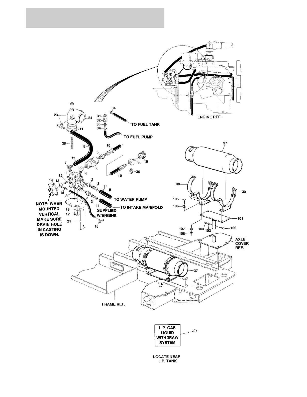
SECTION 2 GROUND CONTROLS
FIGURE 2-5. DUAL FUEL COMPONENTS INSTALLATION - FORD VSG-411 ENGINE OPTION
2-22 400RTS 500RTS 3120830

SECTION 2 GROUND CONTROLS
FIGURE 2-5. DUAL FUEL COMPONENTS INSTALLATION - FORD VSG-411 ENGINE OPTION
ITEM # PART NUMBER QTY. DESCRIPTION REV.
0250790 Ref. DUAL FUEL INSTALLATION - VSG 411 FORD F
1 3720011 1 Regulator, LPG
2 2220364 2 Fitting, Adapter
3 2180535 2 Fitting, Barbed
4 2220648 1 Fitting, 90°
5 2120077 1 Filter-Lock
6 2220003 1 Fitting, Swivel
7 2220675 1 Fitting, 90°
8 2720112
9 2720042
10 2720118 1 Hose, LP (48 in./1.22m Length)
11 1320032 A/R Clamp
12 2180104 1 Fitting
13 2180360 1 Fitting, Tee
14 4360188 1 Switch, Vacuum
15 2180536 1 Fitting, Barbed
16 2180623 1 Fitting, Tee
17 0641405 2 Bolt 1/4"-20NC x 5/8"
18 4761400 2 Lockwasher 1/4"
19 2180387 1 Fitting, Tank Connector
20 Not Used
21 0901778 1 Bracket
22 Not Used
23 0080167 1 Adapter, Air Intake
24 0080092 1 Adapter, Carburetor
25 3840979 1 Rod
26 Not Used
27 1700818 1 Decal - Liquid LPG
28 Not Used
29 Not Used
30 1320023 2 Clamp, LP Tank
31 4640391 1 Valve, Gasoline
32 1320095 1 Clamp, Support
33 2220805 2 Fitting, Straight
34 1320022 2 Clamp
35 2220290 1 Fitting, Tee
35 2220290 1 Fitting, Tee
36 2180389 1 Fitting, Pressure Relief
37 4400040 2 Tank, LP (33.5 Lbs.)
4400275 2 Tank, LP (43.5 Lbs.)
24 in./.61m
28 in./.71m
Hose, LP
Hose, Heater
0253447 Ref. LP TANK BRACKETS INSTALLATION —
101 4844185 2 Support, Tank Bracket
102 0641522 2 Bolt 5/16"-18NC x 2 3/4"
103 4761500 2 Lockwasher 5/16"
104 3311501 2 Nut 5/16"-18NC
105 0641610 8 Bolt 3/8"-16NC x 1 1/4"
3120830 400RTS 500RTS 2-23

SECTION 2 GROUND CONTROLS
FIGURE 2-5. DUAL FUEL COMPONENTS INSTALLATION - FORD VSG-411 ENGINE OPTION
ITEM # PART NUMBER QTY. DESCRIPTION REV.
106 4751600 8 Flatwasher 3/8"
107 4761600 8 Lockwasher 3/8"
108 3311601 Nut 3/8"-16NC
2-24 400RTS 500RTS 3120830

SECTION 2 GROUND CONTROLS
FIGURE 2-5. DUAL FUEL COMPONENTS INSTALLATION - FORD VSG-411 ENGINE OPTION
ITEM # PART NUMBER QTY. DESCRIPTION REV.
3120830 400RTS 500RTS 2-25

SECTION 2 GROUND CONTROLS
FIGURE 2-6. 110 VOLT GENERATOR INSTALLATION (FORD VSG-411) (OPTIONAL)
2-26 400RTS 500RTS 3120830

SECTION 2 GROUND CONTROLS
FIGURE 2-6. 110 VOLT GENERATOR INSTALLATION (FORD VSG-411) (OPTIONAL)
ITEM # PART NUMBER QTY. DESCRIPTION REV.
0250444 Ref. 110 VOLT GENERATOR INSTALLATION (FORD VSG-411)
(OPTIONAL) (PRIOR TO JULY 1994)
0255037 Ref. 110 VOLT GENERATOR INSTALLATION (FORD VSG-411)
(OPTIONAL) (JULY 1994 TO PRESENT)
1 3580134 1 Pulley
2 2460011 1 110 Volt Generator
7003657 1 Control Box Assembly
1 Note: Replacement 110V Control Box comes with 2 stan-
dard Receptacles p/n 4460190. Optional Industrial Twist
Lock Receptacles p/n 44600027 must be ordered separately.
2420203 1 Voltmeter
4360542 1 Breaker, Circuit
2920162 1 Lamp
7020191 1 Switch, Toggle
3520028 1 Plug, Hole
7012558 1 Generator Assembly
7026199 1 Armature with Slip Rings
7020108 4 Brushes
7020109 4 Holders, Brush
7012513 4 Cap, Brush Holder
3580134 1 Pulley
7012514 1 Fan
7020193 1 Cord, Power
7020110 1 Bell End, Front
7020111 1 Bell End, Rear
7020190 2 Bearing
3 7027887 1 Keystock
4 0901650 1 Bracket, Generator Mounting
5 4340569 1 Support, Adjustable
6 0480057 1 V-Belt
7 1360037 1 Sender, Oil (July 1994 to Present)
8 4761600 4 Lockwasher 3/8"
9 3311601 2 Nut 3/8" - 16NC
10 0641511 1 Bolt 5/16"-18NC x 1 3/8"
11 4751500 2 Flatwasher 5/16"
12 4761500 2 Lockwasher 5/16"
13 0961247 1 Bushing
14 0641507 1 Bolt 5/16"-18NC x 7/8”
15 0901609 1 Bracket, Box Mounting
16 3911004 2 Screw, Machine #10-24NC x 1/2"
17 3311001 2 Nut #10-24NC
18 4761000 2 Lockwasher #10
19 Not Used
20 0681610 2 Bolt 3/8"-16NC x 1 1/4" (Grade 8)
21 4751600 2 Flatwasher 3/8"
22 2180749 1 Fitting, 45º (July 1994 to Present)
23 2180360 1 Fitting, Tee (July 1994 to Present)
D
A
3120830 400RTS 500RTS 2-27

SECTION 2 GROUND CONTROLS
FIGURE 2-7. ENGINE INSTALLATION - FORD LSG-423
2-28 400RTS 500RTS 3120830

SECTION 2 GROUND CONTROLS
FIGURE 2-7. ENGINE INSTALLATION - FORD LSG-423
ITEM # PART NUMBER QTY. DESCRIPTION REV.
0254965/0254963 Ref. ENGINE ASSEMBLY (STANDARD PARTS) C/C
1 2000125 1 Engine (Includes 301 thru 303)
2 3600164 1 Pump Assembly - Sunstrand (See Figure 2-13 for Breakdown)
3 3600205 1 Pump Assembly - Barnes (See Figure 2-14 for Breakdown)
4 2720232 1 Hose, Radiator (Bottom)
5 0641810 2 Bolt, 1/2"-13NC x 1 1/4"
6 4761800 2 Lockwasher 1/2"
7 1320012 4 Clamp, Hose
8 4761600 A/R Lockwasher 3/8"
9 2720254 1 Hose, Radiator (Top)
10 3737289 1 Plate, Engine Mounting
11 0711014 4 Bolt 10mm x 30mm
12 Not Used
13 0711020 2 Bolt 10mm x 60mm
14 4562637 2 Spacer
15 4740273 3 Washer, Snubbing
16 3200362 3 Mount, Engine
17 0641826 3 Bolt 1/2"-13NC x 3 1/4"
18 3311805 3 Nut, Lock 1/2"
19 4751800 3 Flatwasher 1/2"
20 4740185 2 Washer, Hardened
21 Not Used
22 2060025 1 Fan
23 0901401 1 Bracket, Terminal Strip
24 1700901 1 Decal, Terminal Cable
25 1670414 1 Cover, Terminal Strip
26 1320070 2 Clamp, Wire
27 3910812 2 Screw #8-32NC x 3/4"
28 4770800 2 Starwasher #8
29 3310801 2 Nut #8-32
30 0100020 A/R Loctite
31 2180360 1 Fitting, Tee
32 4360357 1 Switch, Oil Pressure
33 2220273 1 Fitting, Reducer
34 2420131 1 Sender, Oil Pressure
35 2420149 1 Sender, Water Temperature
36 to 37 Not Used
38 0080092 1 Adapter, Choke
39 Not Used
40 1060045 1 Cable
41 4751600 12 Flatwasher 3/8"
42 0641406 20 Bolt 1/4"-20NC x 3/4"
43 4751400 40 Flatwasher 1/4"
44 3311405 3 Locknut 1/4"
45 Not Used
46 0701010 7 Bolt 10mm x 20mm
47 4740116 7 Lockwasher 10mm
48 4564281 1 Tube, Dipstick
3120830 400RTS 500RTS 2-29

SECTION 2 GROUND CONTROLS
FIGURE 2-7. ENGINE INSTALLATION - FORD LSG-423 (CONTINUED)
ITEM # PART NUMBER QTY. DESCRIPTION REV.
49 2420109 1 Gauge, Dipstick
50 3790152 1 O-Ring, Pump
51 4921714 1 Harness, Wiring (Not Shown)
52 Not Used
53 2720015 10 in. Hose
54 1320022 2 Clamp, Hose
55 to 61 Not Used
62 4844613 1 Exhaust Manifold
63 to 66 Not Used
67 1120432 1 Cap, Vacuum
68 Not Used
69 4360056 1 Stud, Carb
70 0901978 1 Bracket, Muffler Mounting
71 3220089 1 Muffler, Spark Arrestor
72 0340041 2 Clamp, Muffler
73 0641506 4 Bolt 5/6"-18NC x 3/4"
74 4751500 A/R Flatwasher 5/16"
75 3311505 6 Locknut 5/16"
76 3538178 1 Plate, Engine Tray
77 0641608 8 Bolt, 3/8"-16NC x 1"
78 3311601 6 Nut 3/8"
79 4340660 1 Support, Radiator
80 4300038 2 Stud
81 4751700 2 Flatwasher 7/16"
82 4761700 2 Lockwasher 7/16"
83 3311701 2 Nut 7/16"
84 0630375 2 Bolt, Carriage 7/6"-16NC x 1"
85 3940804 6 Screw, Self Tapping #8-32 x 1"
86 4750800 6 Flatwasher #8
87 2680336 1 Fan Shroud
88 1320019 1 Clamp, Muffler
89 0641610 8 Bolt 3/8"-16NC x 1 1/4"
90 3311605 8 Locknut 3/8"
91 to 95 Not Used
96 3620026 1 Radiator
97 1600098 1 Controller, Engine
98 0901419 1 Bracket
99 0641006 4 Bolt #10-24NC x 3/4 Lg.
100 4751000 4 Flatwasher #10
101 3311005 4 Locknut #10-24
102 0902092 1 Bracket
103 2120135 1 Filter, Charge
104 3740061 1 Relay, Start Lockout
105 3740059 1 Relay
106 to 107 Not Required
108 0902093 1 Bracket, Relay Mounting
109 0641510 2 Bolt
110 4761500 2 Lockwasher
111 to 112 Not Required
2-30 400RTS 500RTS 3120830

SECTION 2 GROUND CONTROLS
FIGURE 2-7. ENGINE INSTALLATION - FORD LSG-423 (CONTINUED)
ITEM # PART NUMBER QTY. DESCRIPTION REV.
0254964/0254966 Ref. ENGINE INSTALLATION 4/D
120 to 121 Not Used
122 2 Bracket, Exhaust Hanger Options:
0901387 Prior to S/N 34962
0902382 S/N 34962 to Present
123 1320011 3 Clamp, Muffler
124 0641508 2 Bolt 5/16"-18NC x 1"
125 4751500 8 Flatwasher 5/16"
126 3311505 6 Locknut 5/16"
127 3533664 1 Plate, Radiator Support
128 0630360 2 Bolt, Carriage 5/16"-18NC x 1 1/4"
129 4566520 1 Tube, Exhaust
130 3536151 1 Plate, Exhaust Guard
131 1320058 4 Clamp, Hose
132 4566541 1 Tube, Air Intake
133 0080039 1 Adapter, Elbow
134 1340020 1 Air Cleaner
7004214 1 Element
135 1120161 1 Bonnet
136 0340002 2 Band, Mounting
137 0641408 4 Bolt 1/4"-20NC x 1"
138 4751400 4 Flatwasher 1/4"
139 3311405 4 Locknut 1/4"
140 Not Used
141 4761600 3 Lockwasher 3/8"
142 3311601 3 Nut 3/8"
143 4751600 3 Flatwasher 3/8"
144 3536144 1 Cover, Battery
145 1060360 1 Cable, Battery
146 0630370 2 Tie Down
147 0400002 1 Battery Tie Down
2910479 2 Clips, Tie Down
148 3300029 2 Wingnut 3/8"
149 1060254 1 Cable, Battery
150 0400003 1 Battery
151 3980003 1 Masonite
152 to 154 Not Used
155 0140001 1 Horn
156 Not Required
157 0840025 4 Boot, Cable (Red)
158 Not Used
159 1060221 1 Cable Assembly, 12"
160 1060080 1 Cable Assembly, 30"
161 1060401 1 Cable Assembly, 56"
162 to 166 Not Required
3120830 400RTS 500RTS 2-31

SECTION 2 GROUND CONTROLS
FIGURE 2-7. ENGINE INSTALLATION - FORD LSG-423 (CONTINUED)
ITEM # PART NUMBER QTY. DESCRIPTION REV.
0238044 Ref. PRECISION GOVERNOR INSTALLATION A
201 0901373 1 Bracket, Governor
202 2500004 1 Governor
203 0641408 7 Bolt 1/4"-20NC x 1"
204 3311401 7 Nut 1/4"-20NC
205 4751400 7 Flatwasher 1/4"
206 4761400 7 Lockwasher 1/4"
207 3840898 1 Rod
208 3321401 2 Nut 1/4"-28NF
209 1660157 2 Coupling, Ball Joint
2000125 Ref. ENGINE SUB-ASSEMBLY —
301 2000088 1 Engine, Ford 423
302 1660212 1 Coupling, Hayes
303 4860155 1 Fly Wheel, Ford
Ref. ENGINE COMPONENTS
7000643 1 Carburetor (Standard Gas) with Built-In Choke
7000878 1 Rebuilt Kit
1140009 1 Carburetor - LP Gas
7000877 1 Fuel Shut-Off (With Wire)
7000884 1 Fuel Shut-Off (With Terminal Post)
7012577 1 Vacuum Line Fitting
7012578 1 Vacuum Line Tube Assembly
7000867 1 Engine Harness
7010633 1 Fuel Pump Assembly
7012595 4 Spark Plug
7014677 1 Major Components Kit (Includes 1 each of Standard Gas Car-
buretor, Water Pump, Fuel Pump, Starter and Standard Alternator)
7014678 1 Gasket, Electrical Kit (Includes Upper and Lower Gasket Kits, 1
each of Thermostat, ring Gear, Belt, Coil, Ignition Module, Voltage Regulator, Starter Solenoid and Hose)
7014679 1 Tune-up Kit (Includes 4 Spark Plugs and 1 each of Oil Filter,
Fuel Filter, Cap, Rotator and Ignition Wire Set)
2-32 400RTS 500RTS 3120830

SECTION 2 GROUND CONTROLS
FIGURE 2-7. ENGINE INSTALLATION - FORD LSG-423 (CONTINUED)
ITEM # PART NUMBER QTY. DESCRIPTION REV.
3120830 400RTS 500RTS 2-33

SECTION 2 GROUND CONTROLS
FIGURE 2-8. ENGINE INSTALLATION - FORD LRG-423 DIS/LRG-425
2-34 400RTS 500RTS 3120830

SECTION 2 GROUND CONTROLS
FIGURE 2-8. ENGINE INSTALLATION - FORD LRG-423 DIS/LRG-425
ITEM # PART NUMBER QTY. DESCRIPTION REV.
Ref. ENGINE ASSEMBLY (STANDARD PARTS) OPTIONS:
0255207/0255208 Ref. LRG 423 DIS (PRIOR TO S/N 46528) 7/7
0258320/0258321 Ref. LRG 425 (S/N 46528 TO PRESENT) 6/6
1 2000126 1 Engine, Ford LRG 423 DIS (Prior to S/N 30660)
2000149 1 Engine, Ford LRG 423 DIS (S/N 30660 to S/N 46528)
2000156 1 Engine, Ford LRG 425 (S/N 46528 to S/N 60462)
2000165 1 Engine, Ford LRG 425 (S/N 60462 to Present)
2Not Used
3 3600164 1 Pump Assembly - Sunstrand (See Figure 2-13 for Breakdown)
(Prior to S/N 30660)
3600260 1 Pump Assembly - Sunstrand (See Figure 2-13 for Breakdown)
(S/N 30660 to Present)
4 3200377 1 Mount, Front Engine
5 4566605 1 Tube, Spacer
6 2500005 1 Governor, Precision
7 0902088 1 Bracket, Governor Mounting
8 3841255 1 Rod, Throttle
9 1660157 2 Ball Joint Coupling
10 0902089 1 Bracket, Terminal Mounting Strip
11 0902087 1 Bracket, Fuel Pump Mounting
12 2420149 1 Sender, Water Temperature
13 2420131 1 Sender, Oil Pressure
14 4360357 1 Switch, Oil Pressure
15 2220273 1 Fitting, Reducer
16 2220994 1 Fitting, 1/8" Pipe Cross
17 4300056 1 Stud, Carburetor
18 1 Oil Drain Valve Options:
4640750 Prior to S/N 23751
4640989 S/N 23751 to Present
19 2750532 2.5 ft. Hose, Low Pressure
20 1320032 A/R Clamp, Hose
21 1700901 1 Decal, Terminal Strip
22 1670414 1 Cover, Terminal Strip
23 2220315 1 Fitting, Straight Pipe Barb
24 2720058 1.5 ft. Fuel Line - 5/16" I.D.
25 2180536 1 Fitting, Straight Pipe Barb
26 2720271 2.5 ft. Vacuum Hose - 3/16" I.D.
27 0701022 2 Screw, M10 x 1.5 x 70 Lg.
28 0701014 2 Screw, M10 x 1.5 x 30 Lg.
29 4832000 4 Lockwasher - M10
30 0700810 3 Screw, M8 x 1.25 x 20 Lg.
31 4831900 3 Lockwasher - M8
32 0641812 2 Screw, 1/2"-13NC x 1 1/4" Lg.
33 4761800 2 Lockwasher, 1/2"
34 0641408 A/R Bolt, 1/4"-20NC x 1" Lg.
35 4761400 A/R Lockwasher, 1/4"
36 3311401 A/R Nut, 1/4"-20NC
37 0641406 2 Bolt, 1/4"-20NC x 3/4 Lg.
3120830 400RTS 500RTS 2-35

SECTION 2 GROUND CONTROLS
FIGURE 2-8. ENGINE INSTALLATION - FORD LRG-423 DIS/LRG-425 (CONTINUED)
ITEM # PART NUMBER QTY. DESCRIPTION REV.
38 2 Screw Options:
3911024 Screw #10-24NC x 1 1/2" Lg. (Prior to S/N 32690)
3911026 Screw #10-24NC x 1 5/8" Lg. (S/N 32690 to S/N 46528)
3911014 Screw #10-24NC x 7/8" Lg. (S/N 46528 to Present)
39 2 Nut Options:
3311001 Nut #10-24NC (Prior to S/N 32690)
3311005 Locknut #10-24NC (S/N 32690 to Present)
40 2 Washer Options:
4761000 Lockwasher, #10 (Prior to S/N 32690)
4751000 Flatwasher, #10 (S/N 32690 to Present)
41 3321401 1 Nut, 1/4"-28NF
42 0701017 2 Screw, M10 x 1.5 x 45 Lg. (Prior to S/N 46528)
43 4564281 1 Tube, Dipstick
44 1 Gauge, Dipstick Options:
2420109 Gauge, Dipstick (Prior to S/N 48837)
2420189 Gauge, Dipstick (S/N 48837 to S/N 60462)
2420187 Gauge, Dipstick (S/N 60462 to Present)
45 3740080 3 Relay, Bosch
46 4100025 2 ft. Guard, Hose
47 0100020 A/R Loctite, #56747
48 1 Switch, Oil Pressure Options:
4360405 Prior to S/N 80259
4360037 S/N 80259 to Present
49 2220437 1 Fitting, Male Pipe 1/4" x 1/8"
50 0902361 1 Bracket, Terminal Strip
51 1320022 2 Clamp, Worm Gear (S/N 99226 to Present)
Ref. ENGINE INSTALLATION OPTIONS:
0255209/0255210 Ref. LRG 423 DIS (PRIOR TO S/N 46528) 5/8
0258319/0258322 Ref. LRG 425 (S/N 46528 TO PRESENT) 7/8
101 Not Required
102 1320012 4 Clamp, Hose Worm Gear
103 2060014 1 Fan, 16" Pusher
104 0080212 1 Adapter, Fan Spacer
105 0700822 4 Screw, M8 x 1.25 x 70 Lg.
106 4831900 4 Lockwasher - M8
107 3620026 1 Radiator
108 0181781 1 Bracket, Radiator Support
109 0630360 1 Bolt, 5/16"-18NC x 1 1/4" Lg.
110 4751500 4 Flatwasher, 5/16"
111 3311505 4 Locknut, 5/16"-18NC
112 2 Bolt Options:
0630375 Bolt, 7/16"-14NC x 1" Lg. (Prior to S/N 46528)
0630403 Bolt, 7/16"-14NC x 1 1/2" Lg. (S/N 46528 to Present)
113 4751700 2 Flatwasher, 3/16"
114 3311701 2 Nut, 7/16"-14NC
115 2680386 1 Fan Shroud
2-36 400RTS 500RTS 3120830

SECTION 2 GROUND CONTROLS
FIGURE 2-8. ENGINE INSTALLATION - FORD LRG-423 DIS/LRG-425 (CONTINUED)
ITEM # PART NUMBER QTY. DESCRIPTION REV.
116 6 Flatwasher Options:
4750800 Flatwasher, #8 (Prior to S/N 46528)
4751000 Flatwasher, #10 (S/N 46528 to Present)
117 6 Screw Options:
3940804 Screw, #8-32NC x 1" Lg. Self-Tap (Prior to S/N 46528)
3941004 Screw, #10-24NC x 1/2" Lg. Self-Tap (S/N 46528 to Pres-
ent)
118 1 Engine Tray Options:
4844942 Engine Tray - LRG 423 DIS (Prior to S/N 46528)
4845757 Engine Tray - LRG 425 (S/N 46528 to Present)
119 3200362 3 Mount, Engine
120 4740274 3 Washer, Snubbing
121 0641826 3 Screw, 1/2"-13NC x 3 1/4" Lg.
122 4751800 6 Flatwasher, 1/2"
123 3311805 3 Locknut, 1/2"-13NC
124 0641608 8 Screw, 3/8"-16NC x 1" Lg.
125 4751600 28 Flatwasher, 3/8"
126 3311605 14 Locknut, 3/8"-16NC
127 1 Cable Options:
1060045 Cable (Prior to S/N 64796)
1060221 Cable (S/N 64796 to Present)
128 1600211 1 Controller
129 0901419 1 Bracket
130 0721006 4 Screw #10-24NC x 3/4" Lg.
131 4751000 4 Flatwasher, #10
132 3311005 6 Locknut, #10-24
133 0641407 A/R Screw, 1/4"-20NC x 7/8" Lg.
134 4751400 A/R Flatwasher, 1/4"
135 3311405 A/R Locknut, 1/4"-20NC
136 0902092 1 Bracket, Filter Mount
137 0140001 1 Horn (Prior to S/N 112737)
138 2120135 1 Filter, Charge Pressure
2120136 1 Element, Charge Filter
139 3600205 1 Pump, Gear (See Figure 2-14 for Breakdown)
140 0641610 8 Screw, 3/8"-16NC x 1 1/4" Lg.
141 4761600 2 Lockwasher, 3/8"
142 1340020 1 Air Cleaner
7004214 1 Element, Air Cleaner
143 0340002 2 Mounting Band
144 1120161 1 Bonnet, Air Inlet
145 0080039 2 Adapter, Elbow
146 1320058 6 Clamp, Hose - Worm Gear
147 4561815 1 Tube, Air Inlet (Standard Gas)
4567127 1 Tube, Air Inlet (Dual Fuel)
148 4566673 1 Tube, Air Intake
149 0080124 1 Adapter
150 0080092 1 Adapter, Choke
151 0701010 4 Screw M10 x 1.5 x 20
152 4832000 4 Lockwasher, M10
153 4844962 1 Exhaust Manifold
3120830 400RTS 500RTS 2-37

SECTION 2 GROUND CONTROLS
FIGURE 2-8. ENGINE INSTALLATION - FORD LRG-423 DIS/LRG-425 (CONTINUED)
ITEM # PART NUMBER QTY. DESCRIPTION REV.
154 0340041 2 Clamp, 2" Muffler (Prior to September 1995)
1320019 2 Clamp, 2" Muffler (September 1995 to Present)
155 4566672 1 Tube, Exhaust
156 3220095 1 Muffler, Spark Arrest
157 0901387 1 Bracket (Prior to S/N 34962)
0902382 1 Bracket (S/N 34962 to Present)
158 1320011 1 Clamp, 2 1/2" Muffler
1320011 1 Clamp, 2 1/2" Muffler (Dual Fuel) (Prior to S/N 83238)
1320021 1 Clamp, 2 1/4" Muffler (Dual Fuel) (S/N 83238 to Present)
159 1060360 1 Cable
160 0630370 2 Rod, Tie Down
161 1 Tie Down, Battery Options:
0400002 Tie Down, Battery (Prior to S/N 46528)
2910479 Clips
0400174 Tie Down, Battery (S/N 46528 to Present)
162 3300029 2 Wing Nut, 3/8"-16NC
163 1 Plate, Battery Cover Options:
3536144 Ford LRG 423 DIS (Prior to S/N 46528)
1670841 Ford LRG 425 (S/N 46528 to Present)
164 1060254 1 Cable
165 1 Battery, 12 Volt Options:
0400003 Ford LRG 423 DIS (Prior to S/N 46528)
0400075 Ford LRG 425 (S/N 46528 to Present)
166 1 Masonite Options:
3980003 Ford LRG 423 DIS (Prior to S/N 46528)
3980007 Ford LRG 425 (S/N 46528 to Present)
167 3538735 1 Plate, Exhaust Cover
168 Not Used
169 4921746 1 Wiring Harness
170 3911012 4 Screw #10-24NC x 3/4"
171 1320022 6 Clamp, Worm Gear
172 2720015 10 ft. Hose 1/4"
173 2720160 2 ft. Hose, Low Pressure 1/2"
174 2 Vacuum Cap Options:
1120342 Vacuum Cap (Prior to S/N 64796)
1120432 Vacuum Cap (S/N 64796 to Present)
175 4740185 1 Flatwasher (S/N 46528 to Present)
176 1320180 5 Clamp, Worm Gear (S/N 46528 to Present)
177 4761700 2 Lockwasher 7/16” (S/N 46528 to Present)
178 Not Used
179 2220315 1 Fitting, Straight (S/N 46528 to Present)
180 0840046 1 Boot, Battery Pos. (S/N 103576 to Present)
181 0840047 1 Boot, Battery Neg. (S/N 103576 to Present)
— — — — — — — — — —
0100020 A/R Sealant, Pipe
2-38 400RTS 500RTS 3120830

SECTION 2 GROUND CONTROLS
FIGURE 2-8. ENGINE INSTALLATION - FORD LRG-423 DIS/LRG-425 (CONTINUED)
ITEM # PART NUMBER QTY. DESCRIPTION REV.
2000126/2000149
301 7012680 1 Alternator
302 Use 1660249 1 Coupling (13 Teeth) (Prior to S/N 30660) (was p/n 7012656)
Use 1660250 1 Coupling (15 Teeth) (S/N 30660 to S/N 46528) (was p/n
303 7012681 1 Module, Ignition
304 7012679 1 Starter (Not Shown)
7025145 1 Solenoid, Starter
305 Use 7021869 1 Filter, Oil (was p/n 7014501)
306 7012690 1 Carburetor
7019933 1 Carburetor Kit
7012683 1 Spring
7023471 1 Float Assy
307 7016600 1 Pump, Fuel
7012678 1 Pump, Fuel (Electric)
7000884 1 Solenoid, Fuel
7016601 1 Filter, Fuel
308 7016605 1 Choke, Automatic
309 Use 7019926 1 Hose, Radiator (Top) (was p/n 7016375)
310 Use 7019927 1 Hose, Radiator (Bottom) (was p/n 7016376)
311 Use 7022153 1 Pump, Water (Not Shown) (was p/n 7016638)
312 7019976 1 Flywheel
7022180 1 Ring Gear
7020120 1 Bell Housing
313 7022143 1 Gasket, Exhaust Manifold (Not Shown)
314 70002307 1 Gasket, Exhaust Pipe (Not Shown)
7025126 1 Gasket, Intake Manifold to Head (Not Shown)
7019924 1 Manifold, Exhaust (Not Shown)
315 7022150 1 Belt, Timing (Engine 2000126)
316 7019921 1 Belt, Alternator (Engine 2000126)
317 4360157 1 Switch, Water Temperature (Not Shown)
318 7012682 1 Harness, Engine (Not Shown)
319 7019925 1 PCV Valve (Not Shown)
320 7019929 1 Pulley, Idler (Not Shown)
321 7019930 1 Coil Pack (Not Shown)
7019931 1 Spark Plug Wires (Set) (Not Shown)
7019932 4 Spark Plug Wires (Not Shown)
322 7022178 1 Sensor, Crank Shaft (Not Shown)
323 2420109 1 Gauge, Oil Dipstick (Not Shown) (Engine 2000149)
4564281 1 Tube, Dipstick (Not Shown) (Engine 2000149)
Ref. ENGINE COMPONENTS
7016662)
2000156/2000165
401 7019977 1 Alternator
7019997 1 Regulator
402 Use 1660250 1 Coupling (15 Teeth) (S/N 46528 to S/N 60462) (was p/n
Use 1660249 1 Coupling (13 Teeth) (S/N 60462 to Present) (was p/n 7012656)
403 Use 7023687 1 Module, Ignition (was p/n 7019961)
Ref. ENGINE COMPONENTS
7016662)
3120830 400RTS 500RTS 2-39

SECTION 2 GROUND CONTROLS
FIGURE 2-8. ENGINE INSTALLATION - FORD LRG-423 DIS/LRG-425 (CONTINUED)
ITEM # PART NUMBER QTY. DESCRIPTION REV.
404 7012679 1 Starter (Not Shown)
405 7021869 1 Filter, Oil
406 Use 7019988 1 Carburetor (Engine 2000156) (was p/n 7019974)
7019988 1 Carburetor (Engine 2000165)
7019933 1 Carburetor Kit
7027292 1 Float Assembly
7025122 1 Base, Carburetor
7024321 1 Gasket, Carburetor (Top)
7000646 1 Gasket, Carburetor (Bottom)
7000646 1 Gasket, Carburetor
7016605 1 Choke, Automatic
407 7016600 1 Pump, Fuel (Facet Brand)
7019983 1 Pump, Fuel (Airtex Brand)
7000884 1 Solenoid, Fuel
7016601 1 Filter, Fuel
408 Not Required
409 Use 7019926 1 Hose, Radiator (Top) (was p/n 7016375)
410 Use 7019927 1 Hose, Radiator (Bottom) (was p/n 7016376)
411 7022153 1 Pump, Water (Not Shown)
7019982 1 Tube, Water Pump Inlet (Not Shown)
7019985 1 Pulley, Water Pump (Not Shown)
7022156 1 Thermostat (Not Shown)
7025134 1 Gasket, Water Outlet Connection (Not Shown)
412 7019976 1 Flywheel
7022180 1 Ring Gear
413 7022143 1 Gasket, Exhaust Manifold (Not Shown)
414 70002307 1 Gasket, Exhaust Manifold to Pipe (Not Shown)
7019924 1 Manifold, Exhaust (Not Shown)
7025125 1 Gasket, Intake (Manifold to Cylinder Head) (Not Shown)
415 7019978 1 Tensioner, Belt (Not Shown)
416 7027402 1 Belt, Drive (was p/n 7019979)
417 Not Used
418 7019980 1 Harness, Engine Wiring (Not Shown)
419 to 420 Not Used
421 7019930 1 Coil Pack (Not Shown)
7022157 1 Spark Plug Wires (Set) (Not Shown) (Engine 2000156)
7019931 1 Spark Plug Wires (Set) (Not Shown) (Engine 2000165)
7019932 4 Spark Plug (Not Shown) (Engine 2000165)
422 7022178 1 Sensor, Crank Shaft (Not Shown)
423 7019981 1 Indicator, Oil Level (Not Shown)
0253875 Ref. SPARK ARRESTOR INSTALLATION (OPTIONAL) —
501 3220083 1 Spark Arrestor
0257154 Ref. ENGINE HEATER INSTALLATION (OPTIONAL NOT
SHOWN)
2580048 1 Block Heater Kit (Located Left Side of Intake)
A/1
2-40 400RTS 500RTS 3120830

SECTION 2 GROUND CONTROLS
FIGURE 2-8. ENGINE INSTALLATION - FORD LRG-423 DIS/LRG-425 (CONTINUED)
ITEM # PART NUMBER QTY. DESCRIPTION REV.
3120830 400RTS 500RTS 2-41

SECTION 2 GROUND CONTROLS
FIGURE 2-9. DUAL FUEL COMPONENTS INSTALLATION - FORD LSG-423/LRG-423 DIS/
LRG-425
2-42 400RTS 500RTS 3120830

SECTION 2 GROUND CONTROLS
FIGURE 2-9. DUAL FUEL COMPONENTS INSTALLATION - FORD LSG-423/LRG-423 DIS/ LRG-
425
ITEM # PART NUMBER QTY. DESCRIPTION REV.
Ref. DUAL FUEL COMPONENTS INSTALLATION (FORD LSG423,
LRG423 AND LRG 425 ENGINES)
1 4700005 1 Vaporizer/Regulator
7017515 1 Kit, Rebuilding
2 2120077 1 LPG Filter Lock
3 4360188 1 Vacuum Switch
4 2220675 3 Fitting, 90° Pipe Barb
5 2220251 1 Reducer
6 2200204 1 Pipe Plug 3/4" NPT
7 1320130 2 Clamp, 1"
8 0701010 1 Screw, M10 x 1.5 x 20
0700610 1 Screw, M6 x 1 x 20
9 4832000 1 Lockwasher M10
4831700 1 Lockwasher M6
10 0080124 1 Adaptor, Carburetor
11 1700712 4 Decal, Caution
12 1320022 6 Clamp
13 1120432 1 Cap, Vacuum
14 2720112 2 ft. Hose, Vapor 5/8"
15 2180389 1 Fitting, Relief
16 2720249 1 Hose, L.P. 62" Lg.
17 0902094 1 Bracket, L.P. Filter
18 2180388 1 Filter, Bulkhead
19 2180418 1 Fitting, 1/4" NPT to 3/8", 45° Flare
20 2720144 1 Hose, L.P.
21 2180387 1 Fitting, Tank Connector
22 1320023 2 Clamp, LP Tank
23 4400040 2 Tank, LP (33.5 Lbs.) (Prior to S/N 61097)
4400281 2 Tank, LP (33.5 Lbs.) (S/N 61097 to Present)
4400275 2 Tank, LP (43.5 Lbs.)
24 4640391 1 Lock, Fuel (Prior to June 1995)
25 2200222 1 Pipe Plug 1/4" NPT (S/N 36855 to Present)
26 2220290 1 Fitting, Tee (S/N 36855 to Present)
27 2220504 1 Fitting, 90° 1/4" NPT to 3/8", 45° Flare (S/N 26845 to Present)
0254963/0254964 Ref. DUAL FUEL COMPONENTS INSTALLATION - LSG-423 D/4
0255210/0255208 Ref. DUAL FUEL COMPONENTS INSTALLATION - LRG-423 8/E
0258322/0258321 Ref. DUAL FUEL COMPONENTS INSTALLATION - LRG-425 8/6
51 2220003 1 Fitting, Straight (Not Shown) (LSG-423)
2220082 1 Fitting, 90° (LRG-423/LRG-425) (Prior to S/N 99226)
2220504 1 Fitting, 90° (LRG-423/LRG-425) (S/N 99226 to Present)
52 2220082 1 Fitting, 90° (LSG-423)
Not Required 0 LRG-423/LRG-425
53 2180537 1 Fitting, Nipple (LSG-423)
2180104 1 Fitting, Nipple (LRG-423/LRG-425)
3120830 400RTS 500RTS 2-43

SECTION 2 GROUND CONTROLS
FIGURE 2-9. DUAL FUEL COMPONENTS INSTALLATION - FORD LSG-423/LRG-423 DIS/ LRG-
425 (CONTINUED)
ITEM # PART NUMBER QTY. DESCRIPTION REV.
54 Not Required 0 LSG-423
2180360 1 Fitting, Tee 1/8" NPT (LRG-423/LRG-425)
55 0641510 2 Bolt 5/16"-18NC x 1 1/4" (LSG-423)
0641416 2 Screw 1/4"-20NC x 2" Lg. (LRG-423/LRG-425)
56 4761500 2 Lockwasher 5/16" (LSG-423)
4761400 2 Lockwasher 1/4" (LRG-423/LRG-425)
57 3311501 2 Nut 5/16"-18NC (LSG-423)
3311401 2 Nut 1/4"-20NC (LRG-423/LRG-425)
58 2180250 1 Fitting, Adapter (LSG-423)
2220273 1 Fitting, Adapter (LRG-423/LRG-425)
59 3538436 1 Plate, Mounting (LSG-423)
Not Required 0 LRG-423/LRG-425
60 Not Required 0 LSG-423
0902089 1 Bracket, Mounting (LRG-423/LRG-425)
61 2180749 1 Fitting, 45° (LSG-423)
Not Required 0 LRG-423/LRG-425
62 2180504 1 Fitting, 45° (LSG-423)
Not Required 0 LRG-423/LRG-425
63 Not Required 0 LSG-423
0902361 1 Bracket, Terminal (S/N 33309 to Present)
0253447 Ref. LP TANK BRACKETS INSTALLATION (PRIOR TO S/N 32690) —
101 4844185 2 Support, Tank Bracket
102 0641522 2 Bolt 5/16"-18NC x 2 3/4"
103 4761500 2 Lockwasher 5/16"
104 3311501 2 Nut 5/16"-18NC
105 0641610 8 Bolt 3/8"-16NC x 1 1/4"
106 4751600 8 Flatwasher 3/8"
107 4761600 8 Lockwasher 3/8"
108 3311601 Nut 3/8"-16NC
0256909 Ref. LP TANK BRACKETS INSTALLATION (S/N 32690 TO PRES-
ENT)
151 0902360 1 Support, Tank Bracket (RH) (Prior to S/N 80673)
152 4844185 1 Support, Tank Bracket (LH) (Prior to S/N 80673)
4844185 2 Support, Tank Bracket (S/N 80673 to Present)
153 0641516 1 Bolt 5/16"-18NC x 2" (Prior to S/N 80673)
154 0641522 2 Bolt 5/16"-18NC x 2 3/4"
155 4751500 4 Flatwasher 5/16"
156 3311505 2 Locknut 5/16"-18NC
157 0641610 8 Bolt 3/8"-16NC x 1 1/4"
158 4751600 16 Flatwasher 3/8"
159 3311605 8 Locknut 3/8"-16NC
160 0100011 A/R Loctite
161 1320023 2 Clamp, LP Gas
2
2-44 400RTS 500RTS 3120830

SECTION 2 GROUND CONTROLS
FIGURE 2-9. DUAL FUEL COMPONENTS INSTALLATION - FORD LSG-423/LRG-423 DIS/ LRG-
425 (CONTINUED)
ITEM # PART NUMBER QTY. DESCRIPTION REV.
3120830 400RTS 500RTS 2-45

SECTION 2 GROUND CONTROLS
FIGURE 2-10. GENERATOR INSTALLATION - FORD LSG-423/LRG-423/LRG-425
2-46 400RTS 500RTS 3120830

SECTION 2 GROUND CONTROLS
FIGURE 2-10. GENERATOR INSTALLATION - FORD LSG-423/LRG-423/LRG-425
ITEM # PART NUMBER QTY. DESCRIPTION REV.
0257152 Ref. GENERATOR INSTALLATION 3/B
1 3580250 1 Pulley, Crankshaft
2 1 Belt, Generator Options:
0480090 Ford LSG 423/LRG 423 (Prior to S/N 46528)
0480110 Ford LRG 425 (S/N 46528 to Present)
3 0902372 1 Bracket, Generator Mounting
4 2460011 1 110 Volt Generator
7003657 1 Control Box Assembly
1 Note: Replacement 110V Control Box comes with 2 stan-
dard Receptacles p/n 4460190. Optional Industrial Twist
Lock Receptacles p/n 44600027 must be ordered separately.
2420203 1 Voltmeter
4360542 1 Breaker, Circuit
2920162 1 Lamp
7020191 1 Switch, Toggle
3520028 1 Plug, Hole
7012558 1 Generator Assembly
7026199 1 Armature with Slip Rings
7020108 4 Brushes
7020109 4 Holders, Brush
7012513 4 Cap, Brush Holder
3580134 1 Pulley
7012514 1 Fan
7020193 1 Cord, Power
7020110 1 Bell End, Front
7020111 1 Bell End, Rear
7020190 2 Bearing
5 7027887 1 Key, Woodruff (Prior to S/N 46528)
6 0200530 1 Arm, Adjusting
7 0641612 3 Bolt 3/8"-16NC x 1 1/2"
8 4751600 3 Flatwasher 3/8"
9 4761600 3 Lockwasher 3/8"
10 3311601 1 Nut 3/8"-16NC
11 3580239 1 Pulley, Idler
12 4740275 1 Washer
13 0100011 A/R Loctite
14 4564417 1 Tube, Spacer
15 0641512 1 Bolt 5/16"-18NC x 1 1/2"
16 4751500 3 Flatwasher 5/16"
17 4761500 3 Lockwasher 5/16"
18 4566650 1 Tube, Spacer
19 0701015 2 Bolt 10mm-1.5 x 35mm
20 4812000 2 Flatwasher 10mm
21 4832000 2 Lockwasher 10mm
22 3911008 2 Screw, Machine #10-24 x 1/2"
23 3311001 2 Nut #10-24
24 4761000 2 Lockwasher #10
3120830 400RTS 500RTS 2-47

SECTION 2 GROUND CONTROLS
FIGURE 2-10. GENERATOR INSTALLATION - FORD LSG-423/LRG-423/LRG-425
ITEM # PART NUMBER QTY. DESCRIPTION REV.
25 0901609 1 Bracket, Box Mounting
26 2 Bolt Options:
0641507 2 Bolt 5/16-18NC x 7/8"
0641407 2 Bolt 1/4”-24NC x 7/8"
27 2180360 1 Fitting, Tee
28 4360037 1 Switch, Oil Pressure
29 4932735 1 Wiring, Diagram
30 4711400 2 Flatwasher 1/4”
31 3311405 2 Locknut 1/4”-20NC
32 0641608 1 Bolt 3/8”-16NC x 1”
2-48 400RTS 500RTS 3120830

SECTION 2 GROUND CONTROLS
FIGURE 2-10. GENERATOR INSTALLATION - FORD LSG-423/LRG-423/LRG-425
ITEM # PART NUMBER QTY. DESCRIPTION REV.
3120830 400RTS 500RTS 2-49

SECTION 2 GROUND CONTROLS
FIGURE 2-11. ENGINE INSTALLATION - DEUTZ F3L1011
2-50 400RTS 500RTS 3120830

SECTION 2 GROUND CONTROLS
FIGURE 2-11. ENGINE INSTALLATION - DEUTZ F3L1011
ITEM # PART NUMBER QTY. DESCRIPTION REV.
Ref. ENGINE INSTALLATIONS
0253370 Ref. DEUTZ F3L1011 (AUSTRALIAN SPEC) (PRIOR TO S/N
121830)
0273976 Ref. DEUTZ F3L2011 (AUSTRALIAN SPEC) (S/N 121830 TO PRES-
ENT)
0257247 Ref. DEUTZ F3L1011F (CE SPEC) (PRIOR TO S/N 121830) 11
0273977 Ref. DEUTZ F3L2011 (CE SPEC) (S/N 121830 TO PRESENT) 1
1 Engine Options:
2000107 1 Deutz F3L1011 (includes Items 101-110) (Prior to July 1995)
2000138 1 Deutz F3L1011F (includes Items 201-211) (July 1995 to S/N
121830)
2000242 1 Deutz F3L2011 (includes Items 251-271) (S/N 121830 to
Present)
2 1 Tray, Engine Mounting Options:
4844275 Prior to S/N 121830
4844275 S/N 121830 to Present
3Not Used
4 1 Pump Assembly - Sunstrand Options (See Figure 2-13 for
Breakdown):
3600164 1 Prior to S/N 30660
3600260 1 S/N 30660 to Present
5 0080174 4 Adapter, Engine Mounting
6 0080177 1 Adapter, Air Intake
7 0080172 1 Adapter, Throttle for F3L1011
4460302 1 Adapter, Throttle for F3L1011F/F3L2011
8 3450202 1 Pin, Cotter 1/16" x 1/2"
9 3951003 1 Setscrew #10-24NC x 3/8" for F3L1011
0902244 1 Bracket, Throttle for F3L1011F
0080249 1 Bracket, Throttle for F3L2011
10 4 Bolt Options:
CE Spec
0641844 Bolt 1/2"-13NC x 5 1/2"
Australian Spec
0641844 Bolt 1/2"-13NC x 5 1/2" (Prior to S/N 33431)
0701230 Bolt m12-1.75 x 130mm (S/N 33431 to S/N 72218)
0641840 Bolt 1/2"-13NC x 5" (Prior to S/N 72218)
11 4 Locknut Options:
CE Spec
3311805 Locknut 1/2"-13NC
Australian Spec
3311805 Locknut 1/2"-13NC (Prior to S/N 33431)
3311205 Locknut m12-1.75 (S/N 33431 to S/N 72218)
3311805 Locknut 1/2"-13NC (Prior to S/N 72218)
12 4751800 4 Flatwasher 1/2"
13 0641408 8 Bolt 1/4"-20NC x 1"
14 4761400 10 Lockwasher 1/4"
15 3311401 8 Nut 1/4"-20NC
16 0641512 3 Bolt
17 1060254 1 Cable, Battery
17
1
3120830 400RTS 500RTS 2-51

SECTION 2 GROUND CONTROLS
FIGURE 2-11. ENGINE INSTALLATION - DEUTZ F3L1011 (CONTINUED)
ITEM # PART NUMBER QTY. DESCRIPTION REV.
18 1060093 1 Cable, Battery
19 0140001 1 Horn (Prior to S/N 112737)
20 0641610 2 Bolt 3/8"-16NC x 1 1/4"
21 4751600 11 Flatwasher 3/8"
22 0060023 1 Actuator, Throttle
7008828 1 Cable, Throttle
23 0901838 1 Bracket, Air Cleaner Mounting
24 0701010 4 Bolt, Metric M10 x 20mm
25 4832000 4 Lockwasher 10m
26 4711600 1 Flatwasher 3/8"
27 3311501 3 Nut 5/16"-18NC
28 4761500 3 Lockwasher 5/16"
29 4751600 9 Lockwasher 3/8"
30 1 Battery Options:
0400003 Prior to S/N 48582
0400075 S/N 48582 to Present
31 1 Tie-Down, Battery Options:
0400002 Prior to S/N 48582
0400147 S/N 48582 to S/N 50806
0400174 S/N 50806 to Present
32 1 Seat, Battery Options:
3980003 Prior to S/N 48582
3980007 S/N 48582 to Present
33 0630370 2 Rod, Tie-Down
34 3300029 2 Wingnut 3/8"-16NC
35 1 Cable, Battery Options:
1060360 Australian Spec
1060646 CE Spec
36 4740185 2 Washer, Hardened
37 3311601 9 Nut 3/8"-16NC
38 0641612 6 Bolt 3/8"-16NC x 1 1/2"
39 4843513 1 Air Intake Weldment
40 2180730 1 Fitting, Adapter
41 2420110 1 Sender, Oil Pressure
42 3960407 1 Gasket
43 1340020 1 Air Cleaner Assembly
7004214 1 Element, Air Cleaner
44 0340002 2 Band, Mounting - Air Cleaner
45 1320180 8 Clamp, Hose
46 0080039 1 Elbow, Rubber 90°
47 0721008 2 Screw, Machine #10-24NC x 1" (Prior to S/N 30660)
0701015 2 Screw, Machine 10mm x 35mm (S/N 30660 to Present)
48 4761000 2 Lockwasher #10 (Prior to S/N 30660)
4761400 2 Lockwasher (S/N 30660 to Present)
49 0080046 2 Elbow, Rubber 90°
50 4751000 2 Flatwasher #10 (Prior to S/N 34060)
4751400 2 Flatwasher (S/N 34060 to Present)
51 2720379
52 2720342
3 in./7.6cm
4 in./10cm
Hose
Hose, Air Intake
2-52 400RTS 500RTS 3120830
 Loading...