

Page 1
Service and Maintenance Manual
Model
40H
40H+6
3120240
October 11, 2001
ANSI
Page 2

Page 3

INTRODUCTION - MAINTENANCE SAFETY PRECAUTIONS
SECTION A. INTRODUCTION - MAINTENANCE SAFETY
PRECAUTIONS
A.A GENERAL
This section contains the general safety precautions whi ch
must be o bser ved du ring m ainten anc e of the ae rial pla tform. It is of utmost importance that maintenance personnel pay strict attention to these warnings and precautions
to avoid possible injury to themselves or others , or damage to the equipment. A maintenance program must be
followed to ensure that the machine is safe to operate.
MODIFICATION OF THE MACHINE WITHOUT CERTIFICATION BY
A RESPONSIBLE AUTHORITY THAT THE MACHINE IS AT LEAST
AS SAFE AS ORIGINALLY MANUFACTURED, IS A SAFETY VIOLATION.
The sp ecific precau tion s to be o bser ved d uring main tenance are inserted at the appropriate point in the manual.
These precautions are, for the most part, those that apply
when servicing hydraulic and larger machine component
parts.
Your safety, and that of other s, is th e first cons iderati on
when engaging in the maintenance of equipment. Always
be conscious of weight. Never attempt to move heavy
parts without the aid of a mechanical device. Do not allow
heavy objects to rest in an unstable position. When rai sing
a portion of the equipment , ensure tha t adequa te sup port is
provided.
feed lines to system components c an then be disconnected
with minimal fl uid loss.
A.C MAINTENANCE
FAILURE TO COMPLY WITH SAFETY PRECAUTIONS LISTED IN
THIS SECTION MAY RESULT IN MACHINE DAMAGE, PERSONNEL
INJURY OR DEATH AND IS A SAFETY VIOLATION.
• NO SMOKING IS MANDATORY. NEVER REFUEL DURING ELECTRICAL STORMS. ENSURE THAT FUEL
CAP IS CLOSED AND SECURE AT ALL OTHER
TIMES.
• REMOVE ALL RINGS, WATCHES AND JEWELRY
WHEN PERFORMING ANY MAINTENANCE.
• DO NOT WEAR LONG HAIR UNRESTRAINED, OR
LOOSE-FITTING CLOTHING AND NECKTIES WHICH
ARE APT TO BECOME CAUGHT ON OR ENTANGLED
IN EQUIPMENT.
• OBSERVE AND OBEY ALL WARNINGS AND CAUTIONS ON MACHINE AND IN SERVICEMANUAL.
• KEEP OIL, GREASE, WATER, ETC. WIPED FROM
STANDING SURFACES AND HAND HOLDS.
• USE CAUTION WHEN CHECKING A HOT, PRESSURIZED COOLANT SYSTEM.
• NEVER WORK UNDER AN ELEVATED BOOM UNTIL
BOOM HAS BEEN SAFELY RESTRAINED FROM ANY
SINCE THE MACHINE MANUFACTURER HAS NO DIRECT CONTROL OVER THE FIELD INSPECTION AND MAINTENANCE,
SAFETY IN THIS AREA RESPONSIBILITY OF THE OWNER/OPERATO R.
A.B HYDRAULIC SYSTEM SAFETY
It shou ld be n ote d that the ma chin es hy drau lic s yst ems
operate at ext rem ely high potentia lly dangerous press ures.
Every effort should be made to relieve any system pr essure prior to disconnecting or removing any portion of the
system.
MOVEMENT BY BLOCKING OR OVERHEAD SLING,
OR BOOM SAFETY PROP HAS BEEN ENGAGED.
• BEFORE MAKING ADJUSTMENTS, LUBRICATING OR
PERFORMING ANY OTHER MAINTENANCE, SHUT
OFF ALL POWER CONTROLS.
• BATTERY SHOULD ALWAYS BE DISCONNECTEDDURING REPLACEMENT OF ELECTRICAL COMPONENTS.
• KEEP ALL SUPPORT EQUIPMENT AND ATTACHMENTS STOWED IN THEIR PROPER PLACE.
• USE ONLY APPROVED, NONFLAMMABLE CLEANING
SOLVENTS.
Relieve system pressure by cycling the applicable control
several times with the engine stopped and ignition on, to
direct any line pressure back into the reservoir. Pressure
3120240 – JLG Li ft – a
Page 4

EFFECTI VITY CHANGES
REVISON LOG
Aug, 1985 -Original Issue
Nov. 1985 -Revised
Oct. 1998 -Revised
Aug. 1999 -Revised
October 11, 2001 -Revised
b – JLG Li ft – 3120240
Page 5

TABLE OF CONTENTS
SUBJECT - SECTION, PARAGRAPH PAGE NO.
SECTION A - INTRODUCTION - MAINTENANCE SAFETY PRECAUTIONS
A.A General . . . . . . . . . . . . . . . . . . . . . . . . . . . . . . . . . . . . . . . . . . . . . . . . . . . . . . . . . . . . . . . . . . . . . .a
A.B Hydraulic System Safety . . . . . . . . . . . . . . . . . . . . . . . . . . . . . . . . . . . . . . . . . . . . . . . . . . . . . . . . .a
A.C Maintenance . . . . . . . . . . . . . . . . . . . . . . . . . . . . . . . . . . . . . . . . . . . . . . . . . . . . . . . . . . . . . . . . . . a
EFFECTIVITY CHANGES . . . . . . . . . . . . . . . . . . . . . . . . . . . . . . . . . . . . . . . . . . . . . . . . . . . . . . . . . . . . . .b
TABLE OF CONTENTS . . . . . . . . . . . . . . . . . . . . . . . . . . . . . . . . . . . . . . . . . . . . . . . . . . . . . . . . . . . . . . . I
LIST OF ILLUSTRATIONS . . . . . . . . . . . . . . . . . . . . . . . . . . . . . . . . . . . . . . . . . . . . . . . . . . . . . . . . . . . . . II
LIST OF TABLES . . . . . . . . . . . . . . . . . . . . . . . . . . . . . . . . . . . . . . . . . . . . . . . . . . . . . . . . . . . . . . . . . . . .III
SECTION 1 - SPECIFICATIONS
1.1 Capacities. . . . . . . . . . . . . . . . . . . . . . . . . . . . . . . . . . . . . . . . . . . . . . . . . . . . . . . . . . . . . . . . . . . . . 1-1
1.2 Component Data. . . . . . . . . . . . . . . . . . . . . . . . . . . . . . . . . . . . . . . . . . . . . . . . . . . . . . . . . . . . . . .1-1
1.3 Performance Data.. . . . . . . . . . . . . . . . . . . . . . . . . . . . . . . . . . . . . . . . . . . . . . . . . . . . . . . . . . . . . .1-3
1.4 Torque Requirements.. . . . . . . . . . . . . . . . . . . . . . . . . . . . . . . . . . . . . . . . . . . . . . . . . . . . . . . . . . .1-3
1.5 Lubrication. . . . . . . . . . . . . . . . . . . . . . . . . . . . . . . . . . . . . . . . . . . . . . . . . . . . . . . . . . . . . . . . . . . . 1-3
1.6 Pressure Settings. . . . . . . . . . . . . . . . . . . . . . . . . . . . . . . . . . . . . . . . . . . . . . . . . . . . . . . . . . . . . . . 1-8
1.7 Cylinder Specifications . . . . . . . . . . . . . . . . . . . . . . . . . . . . . . . . . . . . . . . . . . . . . . . . . . . . . . . . . .1-9
1.8 Boom Tape . . . . . . . . . . . . . . . . . . . . . . . . . . . . . . . . . . . . . . . . . . . . . . . . . . . . . . . . . . . . . . . . . . .1-9
1.9 Major Components Weights . . . . . . . . . . . . . . . . . . . . . . . . . . . . . . . . . . . . . . . . . . . . . . . . . . . . .1-10
1.10 Critical Stability Weights . . . . . . . . . . . . . . . . . . . . . . . . . . . . . . . . . . . . . . . . . . . . . . . . . . . . . . . . .1-10
1.11 Serial Number Location (See Figure 1-4.) . . . . . . . . . . . . . . . . . . . . . . . . . . . . . . . . . . . . . . . . . . .1-10
SECTION 2 - PROCEDURES
2.1 General. . . . . . . . . . . . . . . . . . . . . . . . . . . . . . . . . . . . . . . . . . . . . . . . . . . . . . . . . . . . . . . . . . . . . . .2-1
2.2 Servicing And Maintenance Guidelines. . . . . . . . . . . . . . . . . . . . . . . . . . . . . . . . . . . . . . . . . . . . . .2-1
2.3 Lubrication Information. . . . . . . . . . . . . . . . . . . . . . . . . . . . . . . . . . . . . . . . . . . . . . . . . . . . . . . . . .2-2
2.4 Cylinders - Theory Of Operation. . . . . . . . . . . . . . . . . . . . . . . . . . . . . . . . . . . . . . . . . . . . . . . . . . . 2-3
2.5 Valves - Theory Of Operation. . . . . . . . . . . . . . . . . . . . . . . . . . . . . . . . . . . . . . . . . . . . . . . . . . . . . .2-3
2.6 Boom Chains. (See Figure 2-1) . . . . . . . . . . . . . . . . . . . . . . . . . . . . . . . . . . . . . . . . . . . . . . . . . . .2-4
2.7 Wear Pads. . . . . . . . . . . . . . . . . . . . . . . . . . . . . . . . . . . . . . . . . . . . . . . . . . . . . . . . . . . . . . . . . . . .2-6
2.8 Cylinder Checking Procedure. . . . . . . . . . . . . . . . . . . . . . . . . . . . . . . . . . . . . . . . . . . . . . . . . . . . .2-7
2.9 Cylinder Repair. . . . . . . . . . . . . . . . . . . . . . . . . . . . . . . . . . . . . . . . . . . . . . . . . . . . . . . . . . . . . . . . .2-9
2.10 Cylinder Removal And Installation. . . . . . . . . . . . . . . . . . . . . . . . . . . . . . . . . . . . . . . . . . . . . . . . . . 2-12
2.11 Boom Maintenance. . . . . . . . . . . . . . . . . . . . . . . . . . . . . . . . . . . . . . . . . . . . . . . . . . . . . . . . . . . . .2-14
2.12 Tilt Alarm Switch.. . . . . . . . . . . . . . . . . . . . . . . . . . . . . . . . . . . . . . . . . . . . . . . . . . . . . . . . . . . . . . . 2-19
2.13 Horizontal High Speed Cutout Switch Adjustment Procedure. . . . . . . . . . . . . . . . . . . . . . . . . . . . 2-19
2.14 Governor Checks And Addco Adjustment, Ford. . . . . . . . . . . . . . . . . . . . . . . . . . . . . . . . . . . . . . .2-20
2.15 Throttle Checks And Precision Governor Adjustments, Addco (See Figure 2-6.) . . . . . . . . . . . . . 2-21
2.16 Electric Governor And Adjustments - Ford Engines. . . . . . . . . . . . . . . . . . . . . . . . . . . . . . . . . . . .2-22
2.17 Throttle Checks And Adjustments - Deutz F2l511 Engine. (See Figure 2-8.) . . . . . . . . . . . . . . . . 2-29
2.18 Throttle Checks And Adjustments Wisconsin Engine. (See Figure 2-9.) . . . . . . . . . . . . . . . . . . . .2-33
2.19 Throttle Checks And Adjustments - Deutz F3l912 Engine. (See Figure 2-10.) . . . . . . . . . . . . . . . 2-35
2.20 Throttle Checks And Adjustments - Deutz Engine F3l1011. (See Figure 2-11.) . . . . . . . . . . . . . . 2-35
2.21 Pressure Setting Procedures. . . . . . . . . . . . . . . . . . . . . . . . . . . . . . . . . . . . . . . . . . . . . . . . . . . . . .2-38
2.22 Racine Proportional Air Gap Adjustment. . . . . . . . . . . . . . . . . . . . . . . . . . . . . . . . . . . . . . . . . . . . . 2-58
2.23 Swing Bearing. . . . . . . . . . . . . . . . . . . . . . . . . . . . . . . . . . . . . . . . . . . . . . . . . . . . . . . . . . . . . . . . .2-59
2.24 Torque Hub, 2w/d. (See Figure 2-36.) . . . . . . . . . . . . . . . . . . . . . . . . . . . . . . . . . . . . . . . . . . . . . . 2-63
2.25 Torque Hub 4wd. (See Figure 2-37.) . . . . . . . . . . . . . . . . . . . . . . . . . . . . . . . . . . . . . . . . . . . . . . .2-66
2.26 Swing Drive Brake, Mico (Machines Built Prior To May 1992). (See Figure 2-39.) . . . . . . . . . . . . 2-71
2.27 Drive Brake, Mico. (Machines Built Prior To May 1992)(See Figure 2-40.) . . . . . . . . . . . . . . . . . . 2-72
2.28 Swing Drive Brake, Ausco (Machines Built Prior To May 1992). (See Figure 2-41.) . . . . . . . . . . . 2-75
2.29 Drive Brake, Ausco. (Machines Built Prior To May 1992) (See Figure 2-43.). . . . . . . . . . . . . . . . . 2-77
2.30 Drive Brake, Mico. (Machines Built From May 1992 To S/n 33476) (See Figure 2-44.) . . . . . . . . 2-79
2.31 Swing Brake, Mico. (Machines Built From May 1992 To S/n 33476) (See Figure 2-45.). . . . . . . .2-81
3120240 – JLG Lift – i
Page 6

TABLE OF CONTENTS (Continued)
2.32 Drive Brake, Mico. (Machines Built From S/n 33476 To Present) (See Figure 2-46.) . . . . . . . . . .2-83
2.33 Swing Brake, Mico.(Machines Built From S/n 33476 To Present) (See Figure 2-46.) . . . . . . . . . .2-85
2.34 Controllers . . . . . . . . . . . . . . . . . . . . . . . . . . . . . . . . . . . . . . . . . . . . . . . . . . . . . . . . . . . . . . . . . . . .2-87
2.35 Oscillating Axle Bleeding Procedure. . . . . . . . . . . . . . . . . . . . . . . . . . . . . . . . . . . . . . . . . . . . . . . . 2-87
2.36 Oscillating Axle Lockout Test. . . . . . . . . . . . . . . . . . . . . . . . . . . . . . . . . . . . . . . . . . . . . . . . . . . . . .2-88
2.37 Basket Rotator Brake. (See Figure 2-48.) . . . . . . . . . . . . . . . . . . . . . . . . . . . . . . . . . . . . . . . . . . . .2-89
2.38 Free Wheeling Option. . . . . . . . . . . . . . . . . . . . . . . . . . . . . . . . . . . . . . . . . . . . . . . . . . . . . . . . . . . 2-89
2.39 Spark Arrestor Mufflers.. . . . . . . . . . . . . . . . . . . . . . . . . . . . . . . . . . . . . . . . . . . . . . . . . . . . . . . . . .2-89
2.40 Footswitch Adjustment. . . . . . . . . . . . . . . . . . . . . . . . . . . . . . . . . . . . . . . . . . . . . . . . . . . . . . . . . . . 2-89
2.41 Hydraulic Pump W/hayes Pump Drive Coupling Lubrication. . . . . . . . . . . . . . . . . . . . . . . . . . . . .2-89
2.42 Dual Fuel System. . . . . . . . . . . . . . . . . . . . . . . . . . . . . . . . . . . . . . . . . . . . . . . . . . . . . . . . . . . . . . . 2-89
2.43 Preventive Maintenance And Inspection Schedule. . . . . . . . . . . . . . . . . . . . . . . . . . . . . . . . . . . . . 2-90
2.44 Capacity Indicator . . . . . . . . . . . . . . . . . . . . . . . . . . . . . . . . . . . . . . . . . . . . . . . . . . . . . . . . . . . . . .2-92
SECTION 3 - TROUBLESHOOTING
3.1 General. . . . . . . . . . . . . . . . . . . . . . . . . . . . . . . . . . . . . . . . . . . . . . . . . . . . . . . . . . . . . . . . . . . . . . .3-1
3.2 Troubleshooting Information. . . . . . . . . . . . . . . . . . . . . . . . . . . . . . . . . . . . . . . . . . . . . . . . . . . . . . 3-1
3.3 Hydraulic Circuit Checks. . . . . . . . . . . . . . . . . . . . . . . . . . . . . . . . . . . . . . . . . . . . . . . . . . . . . . . . . 3-1
LIST OF FIGURES
FIGURE NO. TITLE PAGE NO.
1-1. Torque Chart. . . . . . . . . . . . . . . . . . . . . . . . . . . . . . . . . . . . . . . . . . . . . . . . . . . . . . . . . . . . . . . . . .1-5
1-2. Lubrication Chart. (Sheet 1 of 2) . . . . . . . . . . . . . . . . . . . . . . . . . . . . . . . . . . . . . . . . . . . . . . . . . . .1-6
1-2. Lubrication Chart. (Sheet 2 of 2) . . . . . . . . . . . . . . . . . . . . . . . . . . . . . . . . . . . . . . . . . . . . . . . . . . .1-7
1-3. Serial Number Locations. . . . . . . . . . . . . . . . . . . . . . . . . . . . . . . . . . . . . . . . . . . . . . . . . . . . . . . . .1-11
2-1. Typical Three Section Boom Assembly. . . . . . . . . . . . . . . . . . . . . . . . . . . . . . . . . . . . . . . . . . . . . .2-5
2-2. Boom Positioning and Support, Cylinder Repair.. . . . . . . . . . . . . . . . . . . . . . . . . . . . . . . . . . . . . . 2-8
2-3. Poly-Pak Seal Installation. . . . . . . . . . . . . . . . . . . . . . . . . . . . . . . . . . . . . . . . . . . . . . . . . . . . . . . . .2-11
2-4. Governor Adjustment, Ford with Addco. . . . . . . . . . . . . . . . . . . . . . . . . . . . . . . . . . . . . . . . . . . . .2-20
2-5. Addco Adjustment, Ford. . . . . . . . . . . . . . . . . . . . . . . . . . . . . . . . . . . . . . . . . . . . . . . . . . . . . . . . .2-21
2-6. Precision Governor Adjustment, Ford. (Sheet 1 of 2). . . . . . . . . . . . . . . . . . . . . . . . . . . . . . . . . . . 2-30
2-7. Precision governor Adjustment, Ford. (Sheet 2 of 2) . . . . . . . . . . . . . . . . . . . . . . . . . . . . . . . . . . . 2-31
2-8. Addco Actuator Adjustments, F2L511. . . . . . . . . . . . . . . . . . . . . . . . . . . . . . . . . . . . . . . . . . . . . . .2-32
2-9. Addco Actuator Adjustments, VG4D. . . . . . . . . . . . . . . . . . . . . . . . . . . . . . . . . . . . . . . . . . . . . . . .2-34
2-10. Addco Actuator Adjustments, F3L912. . . . . . . . . . . . . . . . . . . . . . . . . . . . . . . . . . . . . . . . . . . . . . .2-36
2-11. Addco Actuator Adjustments, F3L1011. . . . . . . . . . . . . . . . . . . . . . . . . . . . . . . . . . . . . . . . . . . . . . 2-37
2-12. Racine Proportional Valve Pressure Setting.(Machines Built Prior To Mid 1987) (Sheet 1 of 2). . 2-39
2-13. Racine Proportional Valve Setting.(Machines Built Prior To Mid 1967) (Sheet 2 of 2) . . . . . . . . .2-40
2-14. Vickers Proportional Valve Pressure Setting, Machines Built To Present (Sheet 1 of 4) . . . . . . . .2-41
2-15. Vickers Proportional Valve Pressure Setting, Machines Built To Present. (Sheet2 of 4) . . . . . . . .2-42
2-16. Vickers Proportional Valve Pressure Setting, Machines Built To Present. (Sheet 3 Of 4) . . . . . . . 2-43
2-17. Vickers Proportional Valve Pressure Setting, Machines Built To Present. (Sheet 4 of 4) . . . . . . . 2-44
2-18. Vickers Proportional Valve Pressure Setting,
Machines Built Prior To 1989 With Accessory Valve. (Sheet 1 of 4). . . . . . . . . . . . . . . . . . . . . . . .2-45
2-19. Vickers Proportional Valve Pressure Setting,
Machines Built Prior To 1989 With Accessory Valve. (Sheet 2 of 4) . . . . . . . . . . . . . . . . . . . . . . .2-46
2-20. Vickers Proportional Valve Pressure Setting,
Machines Built Prior To 1989 With Accessory Valve. (Sheet 3 Of 4) . . . . . . . . . . . . . . . . . . . . . . .2-47
2-21. Vickers Proportional Valve Pressure Setting,
Machines Built Prior To 1989 With Accessary Valve. (Sheet 4 Of 4) . . . . . . . . . . . . . . . . . . . . . . . 2-48
2-22. Solenoid Valve Pressure Settings. (Machines Built Prior To 1992 With Steering Wheel) . . . . . . . 2-49
2-23. Pressure And Flow Settings (Machines Built Prior To May 1992 With Steering Wheel). . . . . . . . . 2-50
2-24. Vickers All Hydraulic Machines Pressure Settings (Sheet 1 of 4). . . . . . . . . . . . . . . . . . . . . . . . . . 2-51
ii – JLG Lift – 3120240
Page 7

TABLE OF CONTENTS
2-25. Vickers All Hydraulic Machines Pressure Settings (Sheet 2 of 4). . . . . . . . . . . . . . . . . . . . . . . . . . 2-52
2-26. Vickers All Hydraulic Machines Pressure Settings (Sheet 3 of 4). . . . . . . . . . . . . . . . . . . . . . . . . . 2-53
2-27. Vickers All Hydraulic Machines Pressure Settings (Sheet 4 of 4). . . . . . . . . . . . . . . . . . . . . . . . . . 2-54
2-28. Solenoid Valve Pressure Settings, Machines Built Before 1995. (Sheet 1 of 2) . . . . . . . . . . . . . .2-55
2-29. Solenoid Valve Pressure Settings, Machines Built from 1995 To Present. (Sheet 2 of 2) . . . . . . . 2-56
2-30. Extend-A-Reach Valve Pressure and Speed Settings Model 40+6. . . . . . . . . . . . . . . . . . . . . . . . 2-57
2-31. Racine Proportional Air Gap Adjustment, Machines Built Prior To Mid 1987. . . . . . . . . . . . . . . . . 2-58
2-32. Swing Bearing Tolerance Boom Placement. . . . . . . . . . . . . . . . . . . . . . . . . . . . . . . . . . . . . . . . . . 2-59
2-33. Swing Bolt Feeler Gauge Check. . . . . . . . . . . . . . . . . . . . . . . . . . . . . . . . . . . . . . . . . . . . . . . . . . . 2-59
2-34. Swing Bearing Tolerance Measuring Point. . . . . . . . . . . . . . . . . . . . . . . . . . . . . . . . . . . . . . . . . . .2-61
2-35. Swing Bearing Torquing Sequence. . . . . . . . . . . . . . . . . . . . . . . . . . . . . . . . . . . . . . . . . . . . . . . . . 2-63
2-36. Torque Hub Assembly, 2/WD.. . . . . . . . . . . . . . . . . . . . . . . . . . . . . . . . . . . . . . . . . . . . . . . . . . . . . 2-64
2-37. Torque Hub 4/WD. . . . . . . . . . . . . . . . . . . . . . . . . . . . . . . . . . . . . . . . . . . . . . . . . . . . . . . . . . . . . .2-68
2-38. Torque Hub Carrier Timing. . . . . . . . . . . . . . . . . . . . . . . . . . . . . . . . . . . . . . . . . . . . . . . . . . . . . . .2-70
2-39. Swing Brake Assembly - Mico (Machines Built Prior To May 1992). . . . . . . . . . . . . . . . . . . . . . . . 2-71
2-40. Drive Brake Assembly - Mico (Machines Built Prior To May 1992). . . . . . . . . . . . . . . . . . . . . . . . .2-73
2-41. Swing Brake Assembly - Ausco (Machines Built Prior to May 1992). . . . . . . . . . . . . . . . . . . . . . .2-76
2-42. Drive Brake, (machines Built Prior to May 1992). . . . . . . . . . . . . . . . . . . . . . . . . . . . . . . . . . . . . . .2-78
2-43. Drive Brake, Mico. (Machines Built From May 1992 To Machine S/N 33476) . . . . . . . . . . . . . . . .2-80
2-44. Swing Brake, Mico. (Machines Built From May 1992 To Machine S/N 33476) . . . . . . . . . . . . . . . 2-82
2-45. Drive Brake, Mico. (Machines Built From S/N 33476 To Present) . . . . . . . . . . . . . . . . . . . . . . . . .2-84
2-46. Swing Brake, Mico. (Machines Built From S/N 33476 to Present) . . . . . . . . . . . . . . . . . . . . . . . . . 2-86
2-47. Basket Rotator Brake. . . . . . . . . . . . . . . . . . . . . . . . . . . . . . . . . . . . . . . . . . . . . . . . . . . . . . . . . . . .2-88
2-48. Boom Tape Replacement Chart . . . . . . . . . . . . . . . . . . . . . . . . . . . . . . . . . . . . . . . . . . . . . . . . . . .2-92
2-49. Capacity Indicator Dial . . . . . . . . . . . . . . . . . . . . . . . . . . . . . . . . . . . . . . . . . . . . . . . . . . . . . . . . . .2-92
3-1. Wiring Diagram - Dual Fuel (Ford Or Wisconsin) . . . . . . . . . . . . . . . . . . . . . . . . . . . . . . . . . . . . . . 3-20
3-2. Wiring Diagram - 110v Generator (Ford). . . . . . . . . . . . . . . . . . . . . . . . . . . . . . . . . . . . . . . . . . . . . 3-21
3-3. Wiring Diagram - 110v Generator (Deutz). . . . . . . . . . . . . . . . . . . . . . . . . . . . . . . . . . . . . . . . . . . .3-22
3-4. Wiring Diagram - Platform Console (W/all Hydraulic Controls).. . . . . . . . . . . . . . . . . . . . . . . . . . .3-23
3-5. Wiring Diagram - Platform Console Standard (Sheet 1 Of 2). . . . . . . . . . . . . . . . . . . . . . . . . . . . . 3-24
3-6. Wiring Diagram - Platform Console Standard (Sheet 2 Of 2). . . . . . . . . . . . . . . . . . . . . . . . . . . . . 3-25
3-7. Wiring Diagram - Standard (Deutz F2l511/f3l912 & Wisconsin
Engine W/ Standard Controls) (Sheet 1 Of 2). . . . . . . . . . . . . . . . . . . . . . . . . . . . . . . . . . . . . . . . . 3-26
3-8. Wiring Diagram - Standard (Deutz F2l4511/f3l912 & Wisconsin
Engine W/ Standard Controls) (Sheet 2 Of 2). . . . . . . . . . . . . . . . . . . . . . . . . . . . . . . . . . . . . . . . . 3-27
3-9. Wiring Diagram - Standard (Deutz F2l511/f3l912 &
Engine W/ Hydraulic Controls) (Sheet 1 Of 2). . . . . . . . . . . . . . . . . . . . . . . . . . . . . . . . . . . . . . . . . 3-28
3-10. Wiring Diagram - Standard (Deutz F2l511/f3l912 & Wisconsin
Engine W/ Hydraulic Controls) (Sheet 2 Of 2). . . . . . . . . . . . . . . . . . . . . . . . . . . . . . . . . . . . . . . . . 3-29
3-11. Wiring Diagram - Standard (Deutz F3l1011 Engine W/ Standard Controls) (Sheet 1 Of 2). . . . . .3-30
3-12. Wiring Diagram - Standard (Deutz F3l1011 Engine W/ Standard Controls) (Sheet 2 Of 2). . . . . .3-31
3-13. Wiring Diagram - Standard (Deutz F3l1011 Engine W/ Hydraulic Controls) (Sheet 1 Of 2). . . . . . 3-32
3-14. Wiring Diagram - Standard (Deutz F3l1011 Engine W/ Hydraulic Controls) (Sheet 2 Of 2). . . . . . 3-33
3-15. Wiring Diagram - Standard (Ford Lrg425 Dis Engine W/ Standard Controls) (Sheet 1 Of 2).. . . .3-34
3-16. Wiring Diagram - Standard (Ford Lrg425 Dis Engine W/ Standard Controls) (Sheet 2 Of 2).. . . .3-35
3-17. Wiring Diagram - Standard (Ford Dis Engine W/ Hydraulic Controls) (Sheet 1 Of 2).. . . . . . . . . . 3-36
3-18. Wiring Diagram - Standard (Ford Dis Engine W/ Hydraulic Controls) (Sheet 2 Of 2).. . . . . . . . . . 3-37
LIST OF TABLES
TABLE NO. TITLE PAGE NO.
2-1 Chain Stretch Tolerance.. . . . . . . . . . . . . . . . . . . . . . . . . . . . . . . . . . . . . . . . . . . . . . . . . . . . . . . . .2-7
2-2 Cylinder Piston Nut Torque Specification . . . . . . . . . . . . . . . . . . . . . . . . . . . . . . . . . . . . . . . . . . . .2-12
2-3 Holding Valve Torque Specifications. . . . . . . . . . . . . . . . . . . . . . . . . . . . . . . . . . . . . . . . . . . . . . . .2-12
2-4 Preventive Maintenance and Inspection Schedule. . . . . . . . . . . . . . . . . . . . . . . . . . . . . . . . . . . . . 2-91
3-1 Platform Assembly Troubleshooting. . . . . . . . . . . . . . . . . . . . . . . . . . . . . . . . . . . . . . . . . . . . . . . .3-2
3120240 – JLG Lift – iii
Page 8

TABLE OF CONTENTS (Continued)
3-2 Boom Assembly Troubleshooting. . . . . . . . . . . . . . . . . . . . . . . . . . . . . . . . . . . . . . . . . . . . . . . . . . 3-3
3-3 Turntable Assembly Troubleshooting. . . . . . . . . . . . . . . . . . . . . . . . . . . . . . . . . . . . . . . . . . . . . . . 3-7
3-4 Chassis Assembly Troubleshooting. . . . . . . . . . . . . . . . . . . . . . . . . . . . . . . . . . . . . . . . . . . . . . . .3-9
3-5 Hydraulic Assembly Troubleshooting. . . . . . . . . . . . . . . . . . . . . . . . . . . . . . . . . . . . . . . . . . . . . . . 3-14
3-6 Electrical Assembly Troubleshooting. . . . . . . . . . . . . . . . . . . . . . . . . . . . . . . . . . . . . . . . . . . . . . . 3-16
(INTENTIONAL BLANK PAGE)
iv – JLG Lift – 3120240
Page 9

SECTION 1 - SPECIFICATIONS
SECTION 1. SPECIFICATIONS
1.1 CAPACITIES.
Fuel Tank - 37 Gallons (140.2 L)
Hydraulic Oil Tank - 37 U.S. Gallons
(104.2 L).
Hydraulic System (Including Tank) - 70 U.S.
Gallons (264.95 L).
Torque Hub Drive - 2.5 Pints (1.18 L).
Torque Hub Swing - 2.0 Pints (1.18 L).
NOTE: Torque Hubs should be one - half full of lubricant.
(EPGL-90)
Engine Crankcase (Ford LSG423) w/Filter
5 quarts (4.73 L).
Engine Crankcase (Ford LRG423) w/Filter
5 quarts (4.73 L).
Engine Crankcase (Deutz F3L912) w/Filter
9.5 quarts (8.99 L).
Engine Crankcase (Deutz F3L1011) w/Filter
6.34 quarts (6 0 L).
Engine Crankcase (Deutz F2L511) w/Filter
3.5 quarts
Engine Crankcase (Wisconsin VG4D) w/Filter
5.0 quarts (4.73 L).
NOTE: Tolerance on all engine rpm settings is plus or minus
10%.
1.2 COMPONENT DATA.
Fuel Consumption High RPM - 2.73 GPH
(10.33 LPH).
Horsepower - 63 @ 2800 RPM, no load.
Engine -Ford LRG-425 D.I.S.
Oil Capacity.
4.50 Quarts (4.25 1) w/Filter.
3.50 Quarts (3.31 1) w/o Filter.
Idle RPM - 1000.
Low RPM - 1800.
High RPM - 2800.
Alternator - 95 Amp, Belt Drive.
Battery - 1000 Cold Cranking Amps, 210 minute reserve
Capacity, 12 VDC.
Fuel Consumption.
Low RPM - 3.45 GPH (13.06 lph).
High RPM - 4.60 GPH (17.41 lph).
Horsepower - 74 @ 3000 RPM, full load.
Cooling System - 16 Quarts (15.14 l.).
Engine - Deutz F3L912.
Oil capacity - 9.5 quarts (8.99L) w/Filter, 8.5
quarts (8.04 L) w/o Filter.
Low RPM 1800.
High RPM 2400.
Alternator - 85 Amp, belt drive.
Engine - Ford LSG423/Lrg423.
Oil capacity - 5 quarts (4.73 L) w/Filter, 4
quarts (3.79 L) w/o Filter.
Cooling System - 16 quarts (15.14 L).
Low RPM - 1000, no load.
Mid RPM - 1800, no load.
High RPM - 3000, no load.
Alternator - 40 Amp, belt drive.
Battery - 1000 cold cranking Amps, 210 minutes reserve capacity,12 VDC.
Fuel Consumption Low RPM - 2.03 GPH
(7.68 LPH).
Battery - 1000 cold cranking Amps, 210 minutes
reserve capacity, 12VDC.
Fuel Consumption Low RPM - 2.03 GPH
(7.68 LPH).
Fuel Consumption High RPM - 2.73 GPH
(10.33 LPH).
Horsepower - 47 @ 2800 RPM, no load.
Engine - Deutz F3L1011.
Oil Capacity - 6.34 quarts (6.0 L) w/Filter, 5.8
quarts (5.5 L) w/0 Filter.
Low RPM 2000.
High RPM 3000.
Alternator - 60 Amp, belt drive.
3120240 – JLG Lift – 1-1
Page 10

SECTION 1 - SPECIFICATIONS
Battery - 1000 cold cranking Amps, 210 minutes reserve capacity, 12VDC.
Fuel Consumption Low RPM - 1.9 GPH (7.19
LPH).
Fuel Consumption High RPM - 2.5 GPH (9.46
LPH).
Horsepower - 42@ 3000 RPM, no load.
Engine - Deutz F2L511.
Oil Capacity - 3.5 quarts (3.31 L) w/Filter, 3.0 quarts (2.84
L) w/o Filter.
Low RPM 1800.
High RPM 2500.
Alternator - 33 Amp, belt drive.
Battery - 1000 cold cranking Amps, 210 minutes
reserve capacity, 12 VDC.
Fuel Consumption Low RPM - 2.03 GPH (7.68 LPH).
Fuel Consumption High RPM - 2.73 GPH (10.34 LPH).
Horsepower - 47 @ 2300 RPM, full load.
Engine - Wisconsin VG4D.
Oil Capacity - 5 quarts (4.73 L) w/Filter, 4.5 quarts (4.26
L) w/o Filter.
Low RPM 1800, no load.
High RPM 2400, no load.
Alternator - 35 Amp, belt drive.
Battery - 1000 cold cranking Amps, 210 minutes
reserve capacity, 12 VDC.
Fuel Consumption Low RPM - 3.21 GPH (12.15 LPH).
Fuel Consumption High RPM - 3.89 GPH (14.72 LPH).
Horsepower - 37 @ 2500 RPM, full load.
Swing System.
Swing Motor - Displacement - 3.0 in3/Rev.
Swing Hub - Ratio - 69:1.
Swing Brake - Automatic spring applied, hydraulically
released disc brakes.
Hydraulic Pump.
Ford LSG423, Deutz F3L912, Wisconsin VG4D with
Racine Valves (Single Speed Drive Motors).
First Section to Proportional Valve-Drive, Lift, Swing -
14.5 GPM (54.88 LPM).
Second Section to High Drive - 9.5 GPM (35.96 LPM).
Third Section to Bang-Bang valve level, Telescope,
Steer, Rotate - 9.5 GPM (35.96 LPM).
Clockwise Rotation.
Ford LSG423, Deutz F3L912, Wisconsin VG4D with
Racine Valves (2 Speed Drive Motors).
First Section to Proportional Valve-Drive, Lift, Swing -
10.8 GPM (40.88 LPM).
Second Section to High Drive - 6.3 GPM (23.85 LPM).
Third Section to Bang-Bang valve level, Telescope,
Steer, Rotate - 6.3 GPM (23.85 LPM).
Clockwise Rotation.
Ford LSG423, Ford LRG423, Deutz F3L912, Deutz
F3L1011, Wisconsin VG4D with Vickers Valves (2 Speed
Drive Motors).
First Section to Proportional Valve-Drive, Lift, Swing 15 GPM (56.78 LPM).
Second Section to High Drive - 9 GPM (34.07 LPM).
Third Section to Bang-Bang Valve Level, Telescope,
Steer, Rotate - 9 GPM (34.07 LPM).
Clockwise Rotation.
Drive System.
Tires - 12.5 x 15, 12 ply rating, 72 PSI. (5 Bar) (4 WD
Same).
Tires - 14 x 17.5, 8 ply rating, 45 PSI. (3 Bar) (4 WD
Same).
Drive Motor Displacement - 2.48 in3/Rev.
Drive Hub Ratio - 49.29:1.
Steer System.
Tires - 12.5 x 15, 12 ply rating, 72 PSI. (5 Bar).
Toe-in, adjust for 1/4 in. (6.35 mm) overall.
Auxiliary Power Pump.
Two section, 3.75 GPM (14.19 lpm) each section, 12
VDC motor, clockwise rotation.
Hydraulic Filter - Tank.
Return - Bypass Type.
10 Microns Nominal.
Hydraulic Filter - On-line (Racine Valve
Only).
Return - Non-Bypass Type.
1-2 – JLG Lift – 3120240
Page 11

SECTION 1 - SPECIFICATIONS
10 Microns Nominal.
1.3 PERFORMANCE DATA.
Travel Speed.
2WD- 4.5 MPH (7.2 KM/HR).
4WD - 4.0 MPH (6.4 KM/HR).
Gradeability.
2WD- 25% or 14°slope, hard surface.
4WD - 40% or 22°slope, hard surface.
Turning Radius .
2WS/2WD- 16 ft. 6 in. (5.1 m).
2WS/4WD - 16 ft. 6 in. (5.1 m).
Boom Speed Lift.
Up 25 - 40 Seconds.
Down 20 - 30 Seconds.
Telescope Speed.
Extend 50 - 80 Seconds.
Retract 40 - 60 Seconds.
Swing Speed 360°.
Left 61 - 92 Seconds.
Machine Stowed Height.
Model 40H (2WD) - 7 ft., 10 in. (2.39 M).
Model 40H (4WD) - 7 ft., 10 in. (2.39 M).
Machine Stowed Length.
Model 40H (2WD) - 25 ft.,2 in. (7.67 M).
Model 40H (4WD) - 25 ft.,2 in. (7.67 M).
Model 40H+6 (4WD) - 26 ft., 10 in. (8.18 M).
Machine Width.
Model 40H/40H+6(2WD/4WD) - 7 ft.,11 in. (2.41 M).
Wheelbase.
Model 40H/40H+6 (2WD/4WD) - 92 in. (2.34 M).
1.4 TORQUE REQUIREMENTS.
Description Torq ue
A. Bearing To Chassis
B. Bearing To Turntable
C. Wheel Lugs 90 lbs.
D. Drive Hub 150 lbs.
E. Swing Hub 110 lbs.
Value (Dry)
110 lbs.
(149 Nm)
220 lbs.
(298 Nm)
(122 Nm)
(204 Nm)
(149 Nm)
Interval
Hours
*200/500
*200/500
100
*200/500
*200/500
Right 61 - 92 Seconds.
NOTE: *Retorque after first 200 hours of operation and
every 500 hours thereafter.
Boom Elevation.
NOTE: See Procedure Section for tightening sequence of
+74° (above horizontal).
-22° (below horizontal).
Model 40H+6.
74° +15° ART. (above horizontal)
-22° -80° ART. (below horizontal)
NOTE: When maintenance becomes necessary or a fas-
1.5 LUBRICATION.
Machine Weight.
Model 40H (2WD) - 11,600 LBS. (5,266 KG.).
Model 40H (4WD) - 12,000 LBS. (5,448 KG.).
Model 40H+6 - 13,350 LBS. (6,005 KG.).
3120240 – JLG Lift – 1-3
turntable bearing bolts.
tener has loosened, refer to the Torque Chart to
determine proper torque value.
Ford LSG423/LRG423/LRG425 Engine.
Single Viscosity Oils (SF, SF-SE, SF-CC, SF-CD).
When Outside Temp is
Consistently
Use SAE
Viscosity Number
Page 12

SECTION 1 - SPECIFICATIONS
-10° F - +60° F.
(-24°C. to +16°C.)
+10° F - + 90° F.
(+12°C. to +32°C.)
Above +32° F. (+0°C.) 30
Above + 50° F. (+10°C.) 40
Multi-Viscosity Oils (SF, SF-SE, SF-CC, SF-CD).
When Outside Temp
is Consistently
Below +10° F. (+12°C.) *5W-20
Below +60° F. (+16°C.) 5W-30
-10° F - +90° F.
(-23°C. to+32°C>)
Above -10° F. (23°C.) 10W-40 or 10W-50
Above +20° F. (-23°C.) 20W-40 or 20W-50
* Not recommended for severe service - including high
RPM operation.
*10W
20W-20
Use SAE
Viscosity Number
10W-30
Deutz F3L912/F3L1011 Engine.
Single Viscosity Oils (CD-SE, CD-SF).
When Outside Temp
is Consistently
-20° F - +25° F.
(-29°C. to +4°C.)
+5° F - + 50° F.
(+15°C. to +10°C.)
+40° F - +85° F.
(+4°C. to +30°C.)
Above 75° F. (24°C.) 40
Multi-Viscosity Oils (CD-SE, CD-SF).
When Outside Temp
is Consistently
-40° F - +75° F.
(-40°C, to +24°C.)
-15° F - +70° F.
(-26°C. to +21°C.)
-15° F - +85° F.
(-26°C. to +30°C.)
+5° F - +75° F.
(-21°C. to +24°C.)
Above +5° F. (-21°C.) 15W-40
* This viscosity can be used at colder temperatures only
with engine oil preheating.
Use SAE
Viscosity Number
*10W
20W-20
30
Use SAE
Viscosity Number
*5W-20 (Synthetic)
10W-30
10W-40
15W-30
Wisconsin VG4D Engine.
Single Viscosity Oils (MS or SD).
When Outside Temp
is Consistently
+15° F - 0° F. 10W
+40° F - + 15° F. 20-20W
+120° F - + 40° F. 30
Multi-Viscosity Oils (MS, SD, SE).
When Outside Temp
is Consistently
Below Zero.( 5W-20
NOTE: Crankcase oil should meet one of the following API
classification grades: SE/CC, SE/CD, SF/CC, SF/
CD.
Table 1-1. Hydraulic Oil.
Hydraulic System
Operating
Temperature Range
0° F to +180° F (-18°C. to 83°C.) 10W
0° F to +210° F (-18° C to 99° C) 10W-20/10W-30
50° F to 210° F (10° C to 99° C) 20W-20
NOTE: Hydraulic oils must have anti-wear qualities at least
to API Service Classification GL-3, and sufficient
chemical stability for mobile hydraulic system service. JLG Industries recommends Mobilfluid 424
hydraulic oil, which has an SAE viscosity of 10W-30
and viscosity index of 152.
When temperatures remain consistently below +20°
F. (-7° C.), an amount of no. 2 diesel fuel, not to
exceed 20% of system capacity, may be added to
the hydraulic oil reservoir. This diesel fuel will “thin”
the hydraulic oil for easier cold weather operation,
and will almost completely dissipate from the hydraulic system over a several month period of time. When
cold weather is past, it may be necessary to drain
and refill the hydraulic system to rid the system of
any remaining diesel fuel.
Aside from JLG recommendations, it is not advisable
to mix oils of different brands or types, as they may
not contain the same required additives or be of
comparable viscosities. If use of hydraulic oil other
than Kendall Hyken 052 is desired or Mobilfluid 424,
contact JLG Industries for proper recommendations.
Use SAE
Viscosity Number
Use SAE
Viscosity Number
SAE Viscosity
Grade
1-4 – JLG Lift – 3120240
Page 13
SECTION 1 - SPECIFICATIONS
Figure 1-1. Torque Chart.
3120240 – JLG Lift – 1-5
Page 14
SECTION 1 - SPECIFICATIONS
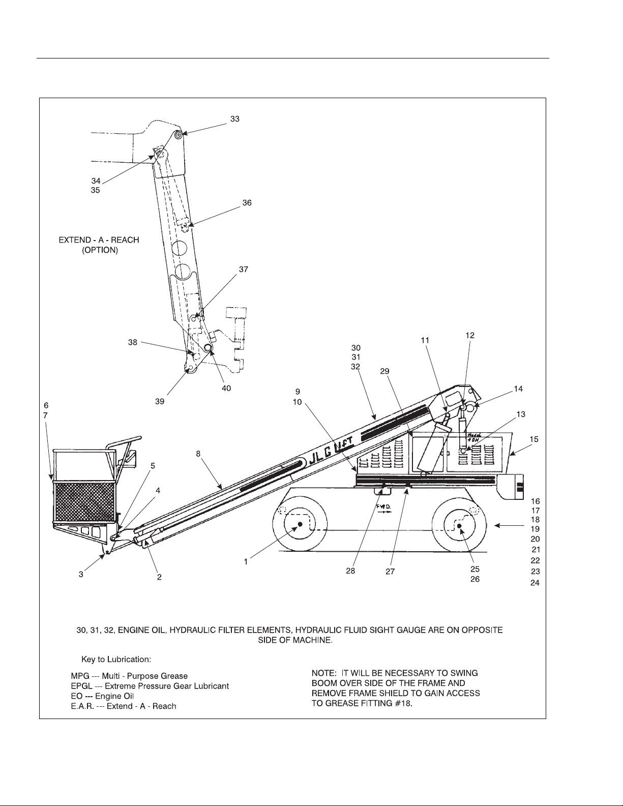
Figure 1-2. Lubrication Chart. (Sheet 1 of 2)
1-6 – JLG Lift – 3120240
Page 15

SECTION 1 - SPECIFICATIONS
INDEX
NO.
1. Wheel Drive Hub Fill Plug/1/2 Full EPGL (SAE - 90) *50/2 years
2. Slave Leveling Cylinder - Barrel End 1 Grease Fitting MPG - Pressure Gun 150
3. Slave Leveling Cylinder - Rod End 1 Grease Fitting MPG - Pressure Gun 150
4. Rotary Platform Control Stand (If Equipped)
5. Rotary Worm Gear (If Equipped) 1 Grease Fitting MPG - Pressure Gun 150
6. Platform Hinges 2 Grease Fittings MPG - Pressure Gun 150
7. Platform Latch & Control Handle Slide Locks N/A SAE 10 - Oil Can A/R
8. Telescope Cylinder Sheave (If Equipped) 1 Grease Fitting MPG - Pressure Gun 150
9. Swing Bearing (Remote Access) 2 Grease Fittings MPG - Pressure Gun 150
10. Lift Cylinder - Barrel End (Remote Access) 1 Grease Fitting MPG - Pressure Gun 150
11. Lift Cylinder - Rod End 2 Grease Fittings MPG - Pressure Gun 150
12. Master Level Cylinder - Rod End 1 Grease Fitting MPG - Pressure Gun 150
13. Master Level Cylinder - Barrel End 1 Grease Fitting MPG - Pressure Gun 150
14. Boom Pivot Bushings 2 Grease Fittings MPG - Pressure Gun 150
15. Engine Crankcase Fill Cap/Drain Plug EO (Refer to end. manual) **10/150
16. Lockout Cylinder - Barrel End
17. Lockout Cylinder - Rod End (If Equipped) 2 Grease Fittings MPG - Pressure Gun 150
18. Oscillating Axle Pivot Pin (If Equipped) 1 Grease Fitting MPG - Pressure Gun *****150
19. Steer Cylinder 2 Grease Fittings MPG - Pressure Gun 150
20. Steer Spindle 2 Grease Fittings MPG - Pressure Gun 150
21. Steer Spindle - 4WD (If Equipped) 4 Grease Fittings MPG - Pressure Gun 150
22. Tie Rod Ends 2 Grease Fittings MPG - Pressure Gun 150
23. Tie Rods - Two Hitch (If Equipped) 4 Grease Fittings MPG - Pressure Gun 150
24. Towing Hitch (If Equipped) 1 Grease Fitting MPG - Pressure Gun 150
25. Wheel Bearings N/A MPG - Repack 500
26. Wheel Drive Hubs - 4WD (If Equipped) Fill Plug/1/2 Full EPGL (SAE - 90) *50/2 yrs.
27. Swing Hub Fill Plug EPGL (SAE - 90) *50/2 yrs.
28. Swing Bearing & Pinion Gear Teeth N/A MPG - Brush 100
29. Door & Access Panel Hinges N/A SAE 10 - Oil Can A/R
30. Hydraulic Filter Element, Return N/A Replacement Element ***40/300
31. Hydraulic Filter Element, Inline N/A Replacement Element ***40/300
32. Hydraulic Fluid (Oil) Fill Plug/1/2 Full HO ****10/2 yrs.
33. E.A.R. Pivot (If Equipped) 2 Grease Fittings MPG - Pressure Gun 150
34. E.A.R. Lift Cylinder Barrel End (If Equipped) 1 Grease Fitting MPG - Pressure Gun 150
35. E.A.R. Link Boom End (If Equipped) 2 Grease Fittings MPG - Pressure Gun 150
36. E.A.R. Lift Cylinder Rod End (If Equipped) 1 Grease Fitting MPG - Pressure Gun 150
37. E.A.R. Slave Cylinder Pivot Points
38. E.A.R. Slave Cylinder Rod End
39. E.A.R. Link Platform End (If Equipped) 1 Grease Fitting MPG - Pressure Gun 150
40. E.A.R. Platform Pivot (If Equipped) 1 Grease Fitting MPG - Pressure Gun 150
COMPONENT NUMBER/TYPE
Platform Pivot
(If Equipped)
(If Equipped)
(If Equipped)
LUBE POINTS
2 Grease Fittings
1 Grease Fitting
1 Grease Fittings MPG - Pressure Gun 100
2 Grease Fittings MPG - Pressure Gun 150
1 Grease Fitting MPG - Pressure Gun 150
LUBE & METHOD INTERVAL
MPG - Pressure Gun
MPG - Pressure Gun
(HOURS)
150
150
*Check oil level after every 50 hours of operation. Change oil after every 2 years (1200 hrs.) of operation.
**Check oil level after every 10 hours of operation. Change oil after every 3 months (150 hrs.) of operation.
***Replace filter element after first 40 hours of operation, then after every 6 months (300 hrs.) of operation thereafter.
****Check oil level after every 10 hours of operation.Change oil after every 2 years(1200 hrs.) of operation.
*****It will be necessary to swing the boom over side of frame and remove the frame shield to gain access to
the grease fitting.
NOTE: Lubrication intervals are based on machine operations under normal conditions. for machines used in multi shift opera-
tions and /or exposed to hostile environments or conditions, lubrication frequencies must be increased accordingly.
Figure 1-2. Lubrication Chart. (Sheet 2 of 2)
3120240 – JLG Lift – 1-7
Page 16

SECTION 1 - SPECIFICATIONS
Lubrication Specifications.
Table 1-2. Lubrication Specifications.
KEY SPECIFICATIONS
MPG Multipurpose Grease having a minimum
dripping point of 350 degrees F. Excellent
water resistance and adhesive qualities;
and being of extreme pressure type
(Timken OK 40 pounds minimum).
EPGL Extreme Pressure Gear Lube (oil) meeting
API Service Classification GL-5 or Mil-Spec
Mil-L-2105.
HO Hydraulic Oil. API Service Classification
GL-3, SAE 10W-20, Viscosity Index 152,
e.g. Kendall Hyken 052 or Mobilfluid 424.
EO Engine (crankcase) Oil. Gas - API SF/SG
class, MIL-L-2104. Diesel - API CC/CD
class, MIL-L-2104B/MIL-L-2104C.
NOTE: Refer to Lubrication Chart, Figure 1-2, for specific
lubrication procedures.
1.6 PRESSURE SETTINGS.
NOTE: All pressure are given in pounds per square inch
(psi), with the metric equivalent, Bar, in parentheses.
Racine Proportional Valve.
Racine.
Main Relief - 2800 psi. (193.06 Bar).
Drive - 2800 psi. (193.06 Bar).
Lift Up - 2800 psi. (193.06 Bar).
Lift Down - 1100 psi. (75.85 Bar).
Swing - 1000 psi. (68.95 Bar).
Solenoid Valve.
Main Relief - 2500 psi. (172.38 Bar).
Tel es c o pe In .
a. 2 Section Boom - 2000 psi
(137.9 Bar).
b. 3 Section Boom - 2500 psi.
(172.38 Bar).
Telescope Out - 1500 psi (103.43 Bar).
Rotate - 2500 psi (172.38 Bar).
Level Up - 2500 psi (172.38 Bar).
Level Down - 1500 psi (103.43 Bar).
Steer.
a. Without Wheel - 1500 psi.(103.43 Bar).
b. Without Wheel - 2500 psi.(172.38 Bar).
Vickers Proportional Valve.
Vickers.
Drive - 3000 psi.(206.85 Bar).
Lift Up - 2500 psi.(172.38 Bar).
Lift Down - 1500 psi. (103.43 Bar).
Telescope In - 2500 psi. (172.38 Bar).
Telescope Out - 1500 psi. (103.43 Bar).
Swing - 1200 psi. (82.74 Bar).
Main Relief - 3200 psi (220.64 Bar).
Sequence Cartridge - 400 psi.
(27.58 Bar).
Pressure Reducing - 600 psi.
(41.37 Bar).
Vickers - Proportional Valve w/o Tele.
Vickers.
Drive - 3000 psi. (206.85 Bar).
Lift Up - 2500 psi. (172.38 Bar).
Lift Down - 1200 psi. (82.74 Bar).
Swing - 1100 psi. (75.85 Bar).
Accessory.
Main Relief - 3200 psi. (220.64 Bar).
Sequence Cartridge - 450 psi. (31.03 Bar).
Pressure Reducing - 600 psi. (41.37 Bar).
1-8 – JLG Lift – 3120240
Page 17
SECTION 1 - SPECIFICATIONS
3 Stack Racine Bang-Bang Valve.
Main Relief - 2500 psi. (172.38 Bar).
Steer - 2000 psi. (137.9 Bar).
4WD Steer Pressure - 2000 psi. (137.9 Bar).
Extend-A-Reach Racine Valve.
Extend Up - 2500 psi. (172.38 Bar).
Extend Down - 800 psi. (55.16 Bar).
NOTE: Refer to Section 2 for pressure setting procedures.
1.7 CYLINDER SPECIFICATIONS
Table 1-3. CYLINDER SPECIFICATIONS.
DESCRIPTION BORE STROKE R OD
DIA.
Master Level 2.50 15.25 1.25
Slave Level 2.50 15.21 1.25
Lift 6.00 23.50 2.50
Lockout
(Oscillating Axle)
Lock-
out
(4WD)
Te le s c op e
(2 Section Boom)
Te le s c op e
(3 Section Boom)
Steer (2WD) 3.00 8.06 1.25
Steer (4WD) 3.00 9.81 1.50
3.00 4.56 1.25
3.00 4.06 1.25
3.00 174.18 2.00
3.00 110.31 2.00
1.8 BOOM TAPE
Two Section Boom (American Standard).
Red - 64 in. (162.56 cm).
Yellow - 41 in. (104.14 cm).
Blue - 71.50 in. (181.61 cm).
Three Section Boom (American Standard).
Red - 24.06 in. (61.11 cm).
Yellow - 20.50 in. (52.07 cm).
Blue - 70.75 in. (179.70 cm).
Two Section Boom (Canadian Standard).
Red - 70.75 in. (179.71 cm).
Yellow - 46.24 in. (117.47 cm).
Blue - 59.49 in. (151.12 cm).
Extend-A-Reach
Lift 3.00 12.687 2.00
Slave 3.50 7.25 1.75
3120240 – JLG Lift – 1-9
Page 18

SECTION 1 - SPECIFICATIONS
1.9 MAJOR COMPONENTS WEIGHTS
TABLE 1-4. COMPONENT WEIGHTS.
Platform - 36" x 48" (91.4 cm x 122 cm)
w/Control Box.
Platform - 36" x 60" (91.4 cm x 152 cm)
w/Control Box.
Platform - 36" x 72" (91.4 cm x 182.88 cm)
w/Control Box.
Platform - 36" x 96" (91.4 cm x 243.84 cm)
w/Control Box.
2 Section Boom (Includes Boom Lift
Cylinder, Rotator and Support).
3 Section Boom (Includes Boom Lift
Cylinder, Rotator and Support).
Turntable Complete. 4687 2126 5925 2688
Frame Complete (Includes Pneumatic Tires and Wheels).
(2WD)
Frame Complete (Includes Pneumatic Tires and Wheels).
(4WD)
Complete Machine - 2WD. 11,600 5,266 13,350 6,055
Complete Machine - 4WD. 12,000 5,448 13,750 6,237
MODEL40H MODEL 40H+6
LBS. KG LBS. KG
170 78 170 78
185 84 185 84
200 90 200 90
240 109 - - - - - -
1795 814 2165 982
2275 1032 2645 1200
5020 2277 5020 2277
5420 2458 5420 2458
1.10 CRITICAL STABILITY WEIGHTS
TABLE 1-5.CRITICAL STABILITY WEIGHTS.
MODEL 40H MODEL 40H+6
LBS. KG LBS. KG
Counterweight
(If Removable)
2:1 1075 487.6 2690 1220.2
Tires
(ballasted Only)
Weight 305 138.4 305 138.4
Engine Ford 525 238.1 525 238.1
Deutz 600 272.2 600 272.2
Wisconsin - - - - - - - - - - - -
1.5:1 910 412.8 2490 1129.5
sIZE 12.5L -15 12.5L -15
1.11 SERIAL NUMBER LOCATION (SEE FIGURE 1-4.)
A serial number plate is affixed to the left rear front of the turntable. If the serial number plate is damaged or missing, the
machine serial number is stamped on the left side of the frame between front and rear wheels, below turntable bearing. In
addition, the last five digits of the serial number are stamped on top of the fly and base end of the boom and on the left side
of the turntable.
1-10 – JLG Lift – 3120240
Page 19

SECTION 1 - SPECIFICATIONS
Figure 1-3. Serial Number Locations.
3120240 – JLG Lift – 1-11
Page 20

SECTION 1 - SPECIFICATIONS
intentional blank page
1-12 – JLG Lift – 3120240
Page 21

SECTION 2. PROCEDURES
SECTION 2 - PROCEDURES
2.1 GENERAL.
This section provides information necessary to perform
maintenance on the aerial platform. Descriptions, techniques and specific procedures are designed to provide
the safest and most efficient maintenance for use by personnel responsible for ensuring the correct installation
and operation of machine components and systems.
WHEN AN ABNORMAL CONDITION IS NOTED AND PROCEDURES
CONTAINED HEREIN DO NOT SPECIFICALLY RELATE TO THE
NOTED IRREGULARITY, WORK SHOULD BE STOPPED AND
TECHNICALLY QUALIFIED GUIDANCE OBTAINED BEFORE WORK
IS RESUMED.
The maintenance procedures included consist of servicing and component removal and installation, disassembly
and assembly, inspection, lubrication and cleaning. Information on any special tools or test equipment is also provided where applicable.
2.2 SERVICING AND MAINTENANCE
GUIDELINES.
General.
The following information is provided to assist you in the
use and application of servicing and maintenance procedures contained in this chapter.
Safety and Workmanship.
Your safety, and that of others, is the first consideration
when engaging in the maintenance of equipment. Always
be conscious of weight. Never attempt to move heavy
parts without the aid of a mechanical device. Do not allow
heavy objects to rest in an unstable position. When raising
a portion of the equipment, ensure that adequate support
is provided.
2. At any time when air, fuel, or oil lines are disconnected, clear adjacent areas as well as the openings
and fittings themselves. As soon as a line or component is disconnected, cap or cover all openings to
prevent entry of foreign matter.
3. Clean and inspect all parts during servicing or maintenance, and assure that all passages and openings
are unobstructed. Cover all parts to keep them
clean. Be sure all parts are clean before they are
installed. New parts should remain in their containers until they are ready to be used.
Components Removal and Installation.
4. Use adjustable lifting devices, whenever possible, if
mechanical assistance is required. All slings (chains,
cables, etc.) should be parallel to each other and as
near perpendicular as possible to top of part being
lifted.
5. Should it be necessary to remove a component on
an angle, keep in mind that the capacity of an eyebolt or similar bracket lessens, as the angle between
the supporting structure and the component
becomes less than 90 degrees.
6. If a part resists removal, check to see whether all
nuts, bolts, cables, brackets, wiring, etc., have been
removed and that no adjacent parts are interfering.
Component Disassembly and Reassembly.
When disassembling or reassembling a component, complete the procedural steps in sequence. Do not partially
disassemble or assemble one part, then start on another.
Always recheck your work to assure that nothing ha s b ee n
overlooked. Do not make any adjustments, other than
those recommended, without obtaining proper approval.
Pressure-Fit Parts.
When assembling pressure-fit parts, use an “anti-seize” or
molybdenum disulfide base compound to lubricate the
mating surface.
Cleanliness.
Bearings.
1. When a bearing is removed, cover it to keep out dirt
1. The most important single item in preserving the
long service life of a machine is to keep dirt and foreign materials out of the vital components. Precautions have been taken to safeguard against this.
Shields, covers, seals, and filters are provided to
keep air, fuel, and oil supplies clean; however, these
items must be maintained on a scheduled basis in
order to function properly.
3120240 – JLG Lift – 2-1
and abrasives. Clean bearings in nonflammable
cleaning solvent and allow to drip dry. Compressed
air can be used but do not spin the bearing.
2. Discard bearings if the races and balls (or rollers)
are pitted, scored, or burned.
3. If bearing is found to be serviceable, apply a light
coat of oil and wrap it in clean (waxed) paper. Do not
Page 22

SECTION 2 - PROCEDURES
unwrap reusable or new bearings until they are
ready to install.
4. Lubricate new or used serviceable bearings before
installation. When pressing a bearing into a retainer
or bore, apply pressure to the outer race. If the bearing is to be installed on a shaft, apply pressure to the
inner race.
Gaskets.
Check that holes in gaskets align with openings in the
mating parts. If it becomes necessary to hand-fabricate a
gasket, use gasket material or stock of equivalent material
and thickness. Be sure to cut holes in the right location, as
blank gaskets can cause serious system damage.
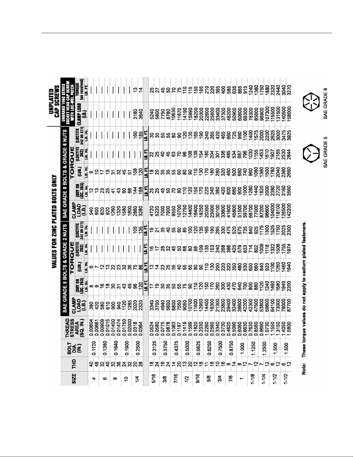
Bolt Usage and Torque Application.
1. Use bolts of proper length. A bolt which is too long
will bottom before the head is tight against its related
part. If a bolt is too short, there will not be enough
thread area to engage and hold the part properly.
When replacing bolts, use only those having the
same specifications of the original, or one which is
equivalent.
2. Unless specific torque requirements are given within
the text, standard torque values should be used on
heat-treated bolts, studs, and steel nuts, in accordance with recommended shop practices.
(See Figure 1-1.)
Hydraulic Lines and Electrical Wiring.
Clearly mark or tag hydraulic lines and electrical wiring, as
well as their receptacles, when disconnecting or removing
them from the unit. This will assure that they are correctly
reinstalled.
Hydraulic System.
Battery.
Clean battery, using a non-metallic brush and a solution of
baking soda and water. Rinse with clean water. After
cleaning, thoroughly dry battery and coat terminals with
an anti corrosion compound.
Lubrication and Servicing.
Components and assemblies requiring lubrication and
servicing are shown in Figures 1-2.
2.3 LUBRICATION INFORMATION.
Hydraulic System.
1. The primary enemy of a hydraulic system is contamination. Contaminants enter the system by various
means, e.g., using inadequate hydraulic oil, allowing
moisture, grease, filings, sealing components, sand,
etc., to enter when performing maintenance, or by
permitting the pump to cavitate due to insufficient
system warm-up or leaks in the pump supply (suction) lines.
2. The design and manufacturing tolerances of the
component working parts are very close, therefore,
even the smallest amount of dirt or foreign matter
entering a system can cause wear or damage to the
components and generally results in faulty operation. Every precaution mst be taken to keep hydraulic oil clean, including reserve oil in storage.
Hydraulic system filters should be checked,
cleaned, and/or replaced as necessary, at the specified intervals required in Figure 1-2. Always examine
filters for evidence of metal particles.
1. Keep the system clean. If evidence of metal or rubber particles are found in the hydraulic system, drain
and flush the entire system.
2. Disassemble and reassemble parts on clean work
surface. Clean all metal parts with non-flammable
cleaning solvent. Lubricate components, as
required, to aid assembly.
Lubrication.
Service applicable components with the amount, type,
and grade of lubricant recommended in this manual, at
the specified intervals. When recommended lubricants are
not available, consult your local supplier for an equivalent
that meets or exceeds the specifications listed.
3. Cloudy oils indicate a high moisture content which
permits organic growth, resulting in oxidation or corrosion. If this condition occurs, the system must be
drained, flushed, and refilled with clean oil.
4. It is not advisable to mix oils of different brands or
types, as they may not contain the same required
additives or be of comparable viscosities. Good
grade mineral oils, with viscosities suited to the
ambient temperatures in which the machine is operating, are recommended for use.
NOTE: Metal particles may appear in the oil or filters of new
machines due to the wear-in of meshing components.
2-2 – JLG Lift – 3120240
Page 23

SECTION 2 - PROCEDURES
Hydraulic Oil.
5. Refer to Table 1-1 for recommendations for viscosity
ranges.
6. JLG recommends Mobilfluid 424 hydraulic oil, which
has an SAE viscosity of 10W-30 and a viscosity
index of 152.
NOTE: Start-up of hydraulic system with oil temperatures
below -15° F. is not recommended. If it is necessary
to start the system in a sub-zero environment, it will
be necessary to heat the oil with a low density,
100VAC heater to a minimum temperature of -15° F.
7. The only exception to the above is to drain and fill
the system with Mobil DTE 11 oil or its equivalent.
This will allow start up at temperatures down to 20°F. However, use of this oil will give poor performance at temperatures above 120° F. Systems using
DTE 11 oil should not be operated at temperatures
above 200°F. under any condition.
Changing Hydraulic Oil.
8. Use of any of the recommended crankcase or
hydraulic oils eliminates the need for changing the
oil on a regular basis. However, filter elements must
be changed after the first 40 hours of operation and
every 250 hours thereafter. If it is necessary to
change the oil, use only those oils meeting or
exceeding the specifications appearing in this manual. If unable to obtain the same type of oil supplied
with the machine, consult local supplier for assistance in selecting the proper equivalent. Avoid mixing petroleum and synthetic base oils. JLG
Industries recommends changing the hydraulic oil
annually.
9. Use every precaution to keep the hydraulic oil clean.
If the oil must be poured from the original container
into another, be sure to clean all possible contaminants from the service container. Always clean the
mesh element of the filter and replace the cartridge
any time the system oil is changed.
10. While the unit is shut down, a good preventive maintenance measure is to make a thorough inspection
of all hydraulic components, lines, fittings, etc., as
well as a functional check of each system, before
placing the machine back in service.
Lubrication Specifications.
Specified lubricants, as recommended by the component
manufacturers, are always the best choice, however,
multi-purpose greases usually have the qualities which
meet a variety of single purpose grease requirements.
Should any question arise, regarding the use of greases in
maintenance stock, consult your local supplier for evalua-
tion. Refer to Table 1-2 for an explanation of the lubricant
key designations appearing in the Lubrication Chart.
2.4 CYLINDERS - THEORY OF OPERATION.
Systems Incorporating Double Acting
Cylinders:
Cylinders are of the double-acting type. Systems incorporating double-acting cylinders are as follows: Lift, Telescope, Platform Leveling, Steer and Lockout. A double
acting cylinder is one that requires oil flow to operate the
cylinder rod in both directions. Directing oil (by actuating
the corresponding control valve to the piston side of the
cylinder) forces the piston to travel toward the rod end of
the barrel, extending the cylinder rod (piston attached to
rod). When the oil flow is stopped, movement of rod will
stop. By directing oil to the rod side of the cylinder, the
piston will be forced in the opposite direction and the cylinder rod will retract.
Holding valves are used in the Lift, Telescope, Slave Level
and lockout circuits to prevent retraction of the cylinder
rod, should a hydraulic line rupture or a leak develop
between the cylinder and its related control valve.
2.5 VALVES - THEORY OF OPERATION.
Solenoid Control Valves (Bang-Bang).
Control valves used are four-way three-position solenoid
valves of the sliding spool design. When a circuit is activated and the control valve solenoid energizes, the spool
is shifted and the corresponding work port opens to permit oil flow to the component in the selected circuit with
the opposite work port opening to reservoir. Once the circuit is deactivated (control returned to neutral) the valve
spool returns to neutral (center) and oil flow is then
directed through the valve body and returns to reservoir. A
typical control valve consist of the valve body, sliding
spool, and two solenoid assemblies. The spool is
machine fitted in the bore of the valve body. Lands on the
spool divide the bore into various chambers, which when
the spool is shifted, align with corresponding ports in the
valve body open to common flow. At the same time other
ports would be blocked to flow. The spool is spring loaded
to center position, therefore when the control is released,
the spool automatically returns to neutral, prohibiting any
flow through the circuit.
3120240 – JLG Lift – 2-3
Page 24

SECTION 2 - PROCEDURES
Proportional Control Valve - Vickers.
CMX series valves provide a power output matching that
required by the load. A small line connected to a loadsensing port feeds load pressure back to the pump. The
pump senses the difference between the load and pump
outlet pressures, and varies the pump displacement to
keep the difference constant. This differential pressure is
applied across the valves meter-in spool, with the effect
that pump flow is determined by the degree of spool
opening, independent of load pressure. Return lines are
connected together simplifying routing of return flow and
to help reduce cavitation. Load sensing lines connect
through shuttle valves to feed the highest load signal back
to the pump. Integral actuator port relief valves, anti cavitation check valves, and load check valves are standard.
The load drop check prevents any drop of a suspended
load before upward movement.
Relief Valves.
Main relief valves are installed at various points with the
hydraulic system to protect associated systems and components against excessive pressure. Excessive pressure
can be developed when a cylinder reaches its limit of
travel and the flow of pressurized fluid continues from the
system control. The relief valve provides an alternate path
for the continuing flow from the pump, thus preventing
rupture of the cylinder, hydraulic line or fitting. Complete
failure of the system pump is also avoided by relieving circuit pressure. The relief valve is installed in the circuit
between the pump outlet (pressure line) and the cylinder
of the circuit, generally as an integral part of the system
valve bank. Relief pressures are set slightly higher than
the load requirement, with the valve diverting excess
pump delivery back to the reservoir when operating pressure of the component is reached.
2. Torque fly boom retract chains, adjust to
28 ft. lbs. (38 NM).
3. Torque fly boom extend chains, adjust to
28 ft. lbs. (38 NM).
4. Cycle boom (extend at least three feet and
return to the fully retracted position).
5. Recheck fly boom retract chains
(28 ft. lbs. (38 NM) required).
6. Recheck fly boom extend chains
(28 ft. lbs. (38 NM) required).
7. Repeat steps #2, #3 and #4 if necessary.
8. Check for proper operation of boom.
JLG Industries, Inc. requires a complete boom disassembly, per instructions outlined in the 2-11 boom disassembly, every two years. All boom chains and related
components (i.e., sheaves, pins, sprockets, wear pads,
etc.) must also be inspected and replaced (as necessary)
during this disassembly.
A more frequent disassembly of the boom assembly and
inspection of the boom chains and related components is
required if machine is exposed to hostile environments or
conditions (i.e. extreme cold, dust, sand, blasting grit, salt,
chemicals, etc.), which could adversely affect boom operation. Such a disassembly is required if either debris has
accumulated inside the boom assembly or an inspection
of the boom chain and related components, in accordance with the INSPECTION PROCEDURES in this section, reveals any discrepancies to the boom chain or
related components.
An immediate disassembly of the boom assembly and
inspection of the boom chains and related components is
required if any of the following conditions occur:
Relief Valves.
Crossover relief valves are used in circuits where the actuator requires an operating pressure lower than that supplied to the system. When the circuit is activated and the
required pressure at the actuator is developed, the crossover relief diverts excess pump flow to the reservoir, individual, integral reliefs are provided for each side of the
circuits.
2.6 BOOM CHAINS. (SEE FIGURE 2-1)
1. Erratic boom operation or unusual noise exists, due
to discrepancies listed in the INSPECTION PROCEDURES in this section, to the boom chains or related
components. See troubleshooting section in Service
Manual for probable causes.
2. Chain adjustment is required more often than specified in Service Manual or links need to be removed
(chain shortened) to make adjustment.
3. Machine is idle for an extended period (6 months or
longer.)
4. Boom is overloaded or sustained a shock load.
Adjusting Procedures.
FAILURE TO DISASSEMBLE THE BOOM ASSEMBLY AND PROP-
ENSURE MACHINE IS ON A FIRM AND LEVEL SURFACE.
1. Fully retract boom in the horizontal position.
2-4 – JLG Lift – 3120240
ERLY INSPECT AND/OR REPLACE THE BOOM CHAINS AND
RELATED COMPONENTS (I.E., SHEAVES, PINS, SPROCKETS,
WEAR PADS, ETC.) COULD RESULT IN THE DAMAGE AND/OR
BREAKAGE OF THE BOOM CHAINS AND/OR RELATED COMPO-
Page 25

SECTION 2 - PROCEDURES
NENTS. DAMAGE AND/OR BREAKAGE OF THESE ITEMS COULD
RESULT IN UNCONTROLLED EXTENSION OR RETRACTION OF
Figure 2-1. Typical Three Section Boom Assembly.
Inspection Procedures.
5. Inspect boom chains for the following condition:
Wear: Always inspect that segment of chain that
operates over a sheave. As the chain flexes over
the extend/retract sheaves, joints and plate edges
very gradually wear. Chain “stretch” can be measured using a manufacturers wear scale or steel
tape. When chains have elongated 3% they must
be removed and replaced. Refer to Table 1 for
proper chain specifications and allowable stretch
tolerances. Peening and wear of chain plate
edges are caused by sliding over a chain worn
contact face of a sheave, or unusually heavy
loads. All of the above require replacement of the
chain and correction of the cause. Chain side
wear, noticeable when pin heads and outside
plates show a definite wear pattern, is caused by
misalignment of the sheave/chain anchors and
must be corrected promptly. Do not repair chains;
if a section of chain is damaged, replace the
entire chain set.
THE BOOM ASSEMBLY AND COULD CAUSE SERIOUS INJURY OR
DEATH TO PERSONNEL OPERATING THE JLG BOOM LIFT.
a film of oil on all chain surfaces will inhibit rusting
and corrosion. This is important as corrosion of
highly stressed, hardened steel chain components can cause a major reduction in the load
capacity of leaf chain and result in link plate
cracking.
NOTE: The need for lubrication can be determined by the
presence of rust on the exposed portions of chain.
Rust and Corrosion: Rust and corrosion will
cause a major reduction in the load carrying
capacity of the chain, because these are primary
reasons for side plate cracking. The initial lubrication at the factory is applied in a hot dip tank to
assure full penetration into the joint. Do not steam
clean or degrease this lubricant on chains. A
grade of SAE 30 or 40 weight, non detergent
motor oil should be used as a supplemental lubricant and a film of this oil should be constantly
maintained on the surfaces and internal joints. At
time of chain installation, factory Lube must be
supplemented by a maintenance program to provide a film of oil on the chains at all times. If
chains are corroded, they must be inspected,
especially the outside plates, for cracks in-line
with the pins. If cracks are found, replace the
chain; if no cracks are discovered, lubricate the
chains by dipping in heated oil, and reinstall on
the machine. Keep chains lubricated.
Fatigue Cracks: Fatigue is a phenomenon
that affects most metals, and is the most
Lubrication: One of the most important but often
overlooked factors is adequate lubrication. In
addition to reducing internal friction, maintaining
3120240 – JLG Lift – 2-5
common cause of chain plate failures.
Fatigue cracks are found through the link
holes, perpendicular (90 degrees) from the
Page 26
SECTION 2 - PROCEDURES
pin in-line position. Inspect chains carefully
after long time use and heavy loading for
this type of crack. If any cracks are
discovered, replace all chains, as seemingly
sound plates are on the verge of cracking.
Fatigue and ultimate strength failures on
JLG Lifts are incurred as a result of severe
abuse as design specs are well within the
rated lifting capacity of these chains.
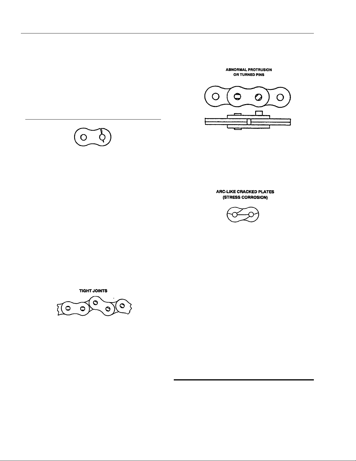
Tight Joints: All joints in the roller chain should
flex freely. On roller chain, tight joints are usually
caused by rust/corrosion, or the inside plates
“walking” off the bushing. Limber up rusty/corroded chains (after inspecting care fully) with a
heavy application of oil (preferably a hot oil dip).
Tap inside “walking” plates inward; if “walking”
persists, replace the chain. This type of problem
is accelerated by poor lubrication maintenance
practice, and most tight joint chains have been
operated with little or no lubrication. Tight joints
on leaf chain are generally caused by:
1. Bent pins or plates.
2. Rusty joints.
3. Peened plate edges.
extend in an arc-like path, often parallel to the rolling grain of the material.
Also, more then one crack can often appear on a
link plate. In addition to rusting, this condition can
be caused by exposure to an acidic or caustic
medium or atmosphere. Stress corrosion is an
environmentally assisted failure. Two conditions
must be present - corrosive agent and static
stress. In the chain, static stress is present at the
aperture due to the press fit pin.
No cycle motion is required and the plates can
crack during idle periods. The reactions of many
chemical agents (such as battery acid fumes) with
hardened metals liberate hydrogen which attacks
and weakens the metal grain structure.
Oil rusty chains, and replace chains with bent or
peened chain components. Keep chains lubricated.
Protruding or Tur ned P i ns: Chains operating
with inadequate lube generate tremendous friction between the pin and plates (pin and bushing
on roller chain). In extreme cases, this frictional
torque can actually turn the pins in the outside
press-fit plates. Inspect for turned pins, which can
be easily spotted as the “V” flats on the pin heads
are no longer in line. Replace all chains showing
evidence of turned or protruding pins. Keep
chains lubricated.
Stress Corrosion Cracking: The outside link
plates, which are heavily press-fitted to the pins,
are particularly susceptible to stress corrosion
cracking. Like fatigue cracks, these initiate at the
point of highest stress (aperture) but tend to
Chain Anchors, Sheaves and Pins: An inspection of the chain must include a close examination
of chain anchors, sheaves and pins. Check chain
anchors for wear breakage and misalignment.
Anchors with worn or broken fingers should be
replaced. They should also be adjusted to eliminate twisting the chain for an even load distribution.
Sheaves should be inspected for worn flanges,
which would indicate misalignment, and wear on
the outside diameter of the sheave. A worn
sheave can mean several problems, as follows:
1. Chains too tight.
2. Sheave bearings/pin bad.
3. Bent/misaligned chains.
2.7 WEAR PADS.
1. Shim up wear pads within 1/16 in. (1.59 mm) tolerance between wear pad and adjacent surface.
2. Replace wear pads when worn within 1/8 in. (3.18
mm) of threaded insert.
2-6 – JLG Lift – 3120240
Page 27
Table 2-1. Chain Stretch Tolerance.
SECTION 2 - PROCEDURES
Chain
Size
0.50 in. (1.27 cm) pitch 14 in. (36 cm) or 28 pitches 0.42 in. (1.07 cm)
0.625 in. (1.59 cm) pitch 15 in. (38 cm) or 24 pitches 0.45 in. (1.14 cm)
0.75 in. (1.91 cm) pitch 15 in. (38 cm) or 20 pitches 0.45 in. (1.14 cm)
1 in. (2.54 cm) pitch 14 in. (36 cm) or 14 pitches 0.42 in. (1.07 cm)
1.25 in. (3.18 cm) pitch 15 in. (38 cm) or 12 pitches 0.45 in. (1.14 cm)
1.75 in. (4.45 cm) pitch 14 in. (36 cm) or 8 pitches 0.42 in. (1.07 cm)
2 in. (5.08 cm) pitch 14 in. (36 cm) or 7 pitches 0.42 in. (1.07 cm)
2.8 CYLINDER CHECKING PROCEDURE.
NOTE: Cylinder checks must be performed any time a cylin-
der component is replaced or when improper system
operation is suspected.
Cylinders Without Counterbalance Valves.
Steer Cylinder and Master Cylinder.
3. Using all applicable safety precautions, activate
engine and fully extend cylinder to be checked. Shut
down engine.
4. Carefully disconnect hydraulic hose from retract port
of cylinder. There will be initial weeping of hydraulic
fluid which can be caught in a suitable container.
After the initial discharge there should be no further
leakage from the retract port.
Pin To Pin
Measurement
Allowable
Stretch
Cylinders With Single Counterbalance
Valve.
Lift Cylinder, Telescope Cylinder and Extend- A-Reach Lift
Cylinder.
OPERATE ALL FUNCTIONS FROM GROUND CONTROLS.
1. Using all applicable safety precautions, activate
hydraulic system.
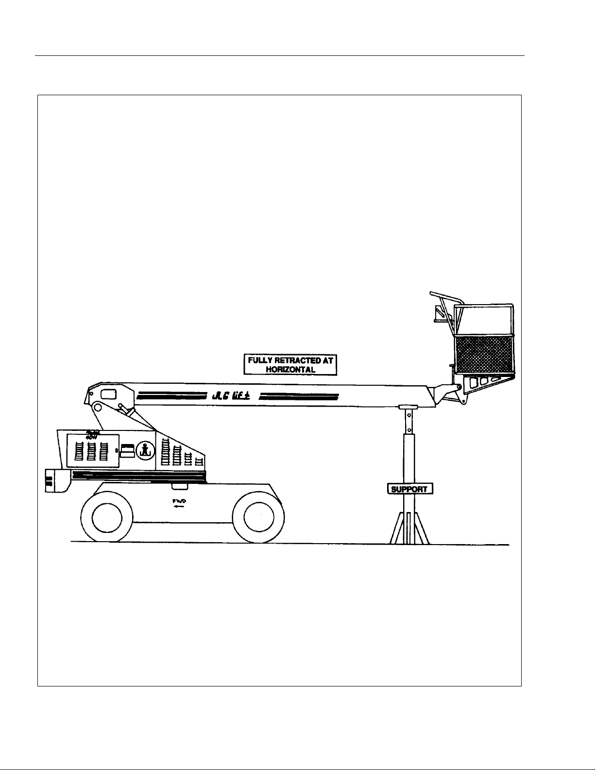
WHEN WORKING ON THE LIFT CYLINDER, RAISE THE BOOM TO
HORIZONTAL AND PLACE A BOOM PROP APPROXIMATELY 1
INCH (2.50 CM) BELOW THE BOOM. DO NOT WORK ON THE CYLINDER WITHOUT A SUITABLE PROP IN PLACE. REFER TO FIGURE 2-2.
5. Activate engine and extend cylinder.
6. If cylinder retract port leakage is less than 6-8 drops
per minute, carefully reconnect hose to port and
retract cylinder. If leakage continues at a rate of 6-8
drops per minute or more, cylinder repairs must be
made.
7. With cylinder fully retracted, shut down engine and
carefully disconnect hydraulic hose from cylinder
extend port.
8. Activate engine and retract cylinder. Check extend
port for leakage.
9. If extend port leakage is less than 6-8 drops per
minute, carefully reconnect hose to extend port,
then activate cylinder through one complete cycle
and check for leaks. If leakage continues at a rate of
6-8 drops per minute or more, cylinder repairs must
be made.
2. After completing the above, shut down hydraulic
system and allow machine to sit for 10-15 minutes.
Turn IGNITION SWITCH to ON, move control switch
or lever for applicable cylinder in each direction,
then turn IGNITION SWITCH to OFF. This is done to
relieve pressure in the hydraulic lines. Carefully
remove hydraulic hoses from appropriate cylinder
port block.
3. There will be initial weeping of hydraulic fluid, which
can be caught in a suitable container. After the initial
discharge, there should not be any further leakage
from the ports. If leakage continues at a rate of 6-8
drops per minute or more, the following cylinder
repairs must be made. If the retract port is leaking,
the piston seals are defective and must be replaced.
If the extend port is leaking, the counterbalance
valve is defective and must be replaced.
4. If no repairs are necessary or when repairs have
been made, carefully reconnect hydraulic hoses to
the appropriate ports.
3120240 – JLG Lift – 2-7
Page 28
SECTION 2 - PROCEDURES
Figure 2-2. Boom Positioning and Support, Cylinder Repair.
2-8 – JLG Lift – 3120240
Page 29

SECTION 2 - PROCEDURES
5. If used, remove boom prop from beneath boom,
activate hydraulic system and run cylinder through
one complete cycle to check for leaks.
Cylinders With Dual Counterbalance Valves.
Platform Slave Level Cylinder, Lockout Cylinder
and Extend-A-Reach Level Cylinder.
OPERATE ALL FUNCTIONS FROM GROUND CONTROL STATION
ONLY.
1. Using all applicable safety precautions, activate
hydraulic system.
2. When working on the platform slave level cylinder,
stroke platform slave level cylinder forward until platform sits at a 45° angle.
3. Shut down hydraulic system and allow machine to
sit for 10-15 minutes. If machine is equipped with a
bang-bang or proportional control valves, turn IGNITION SWITCH to ON, move control switch or lever
for applicable cylinder in each direction, then turn
IGNITION SWITCH to OFF. If machine is equipped
with hydraulic control valves, move control lever for
applicable cylinder in each direction. This is done to
relieve pressure in the hydraulic lines. Carefully
remove hydraulic hoses from appropriate cylinder
port block.
4. There will be initial weeping of hydraulic fluid which
can be caught in a suitable container. After the initial
discharge, there should not be any further leakage
from the ports. If leakage continues at a rate of 6-8
drops per minute or more, the counterbalance valve
is defective and must be replaced.
5. To check piston seals, carefully remove the counterbalance valve from the retract port. After initial discharge there should not be any further leakage from
the ports. If leakage occurs at a rate of 6-8 drops per
minute or more, the piston seals are defective and
must be replaced.
6. If no repairs are necessary or when repairs have
been made, replace counterbalance valve and carefully connect hydraulic hoses to cylinder port block.
2.9 CYLINDER REPAIR.
NOTE: The following are general procedures that apply to
all of the cylinders on this machine. Procedures that
apply to a specific cylinder will be so noted.
Disassembly.
DISASSEMBLY OF THE CYLINDER SHOULD BE PERFORMED ON
A CLEAN WORK SURFACE IN A DIRT FREE WORK AREA.
1. Connect a suitable auxiliary hydraulic power source
to the cylinder port block fitting.
DO NOT FULLY EXTEND CYLINDER TO THE END OF STROKE.
RETRACT CYLINDER SLIGHTLY TO AVOID TRAPPING PRESSURE.
2. Operate the hydraulic power source and extend the
cylinder. Shut down and disconnect the power
source. Adequately support the cylinder rod, if applicable.
CYLINDERS WITH DOUBLE HOLDING VALVES. BEFORE REMOVING HOLDING VALVES CRACK BLEEDERS TO RELEASE PRESSURE.
3. If applicable, remove the cartridge-type holding
valve and fittings from the cylinder port block. Discard o-rings.
4. Place the cylinder barrel into a suitable holding fixture. Tap around outside of cylinder head retainer
with a suitable hammer to shatter loctite.
5. Using a suitable spanner wrench, loosen the cylinder head retainer, if applicable, and/or cylinder head
gland, and remove from cylinder barrel.
6. Attach a suitable pulling device to the cylinder rod
port block end or cylinder rod end, as applicable.
7. If used, remove lifting device from upright or remove
prop from below boom, activate hydraulic system
and run cylinder through one complete cycle to
check for leaks.
EXTREME CARE SHOULD BE TAKEN WHEN REMOVING THE CYLINDER ROD, HEAD, AND PISTON. AVOID PULLING THE ROD OFFCENTER, WHICH COULD CAUSE DAMAGE TO THE PISTON AND
CYLINDER BARREL SURFACES.
3120240 – JLG Lift – 2-9
Page 30

SECTION 2 - PROCEDURES
7. With the barrel clamped securely, apply pressure to
the rod pulling device and carefully withdraw the
complete rod assembly from the cylinder barrel.
8. Using suitable protection, clamp the cylinder rod in
a vise or similar holding fixture as close to the piston
as possible.
9. Remove the set screw (s), if applicable, and nut
which attach the piston to the rod, and remove the
piston. Discard self-locking set screws.
10. Remove the piston rings.
11. Remove and discard the piston o-rings, seal rings,
and backup rings.
12. Remove the set screw, if applicable, piston spacer,
and wear ring, if applicable, from the rod.
13. Remove the rod from the holding fixture. Remove
the cylinder head gland and retainer, if applicable.
Discard the o-rings, back-up rings, rod seals, and
wiper seals.
Cleaning and Inspection.
1. Clean all parts thoroughly in an approved cleaning
solvent.
2. Inspect the cylinder rod for scoring, tapering, ovality,
or other damage. If necessary, dress rod with
Scotch Brite or equivalent. Replace rod if necessary.
3. Inspect threaded portion of rod for excessive damage. Dress threads as necessary.
4. Inspect inner surface of cylinder barrel tube for scoring or other damage. Check inside diameter for
tapering or ovality. Replace if necessary.
5. Inspect threaded portion of barrel for damage. Dress
threads as necessary.
6. Inspect piston surface for damage and scoring and
for distortion. Dress piston surface or replace piston
as necessary.
7. Inspect seal and o-ring grooves in piston for burrs
and sharp edges. Dress applicable surfaces as necessary.
11. Inspect cylinder head outside diameter for scoring
or other damage and ovality and tapering. Replace
as necessary.
12. If applicable, inspect thread ring for scoring or other
damage. Dress threads or applicable surfaces as
necessary.
13. If applicable, inspect seal grooves in thread ring for
burrs and sharp edges. Dress applicable surfaces
as necessary.
14. If applicable, inspect rod and barrel bushings for
signs of correct lubrication and excessive wear.
Replace as necessary.
15. Inspect travel limiting collar or spacer for burrs and
sharp edges. If necessary, dress inside diameter
surface with Scotch Brite or equivalent.
16. If applicable, inspect port block fittings and holding
valve. Replace as necessary.
17. Inspect the oil ports for blockage or the presence of
dirt or other foreign material. Repair as necessary.
18. If applicable, inspect piston rings for cracks or other
damage. Replace as necessary.
NOTE: Steps (19) through (22) apply to the 3 Section Boom
telescope cylinder only.
19. Inspect chain sheave bushings for scoring, tapering,
ovality and for excessive wear and evidence of correct lubrication. Replace bushing as necessary.
20. Inspect sheave chain groove for damage. Replace
sheave assembly as necessary.
21. Inspect sheave attach pin for scoring or other damage and for evidence of correct lubrication. Dress
pin surface with Scotch Brite or equivalent or
replace pin as necessary.
22. Inspect sheave pin lubrication drilling and fitting for
blockage or the presence of dirt or other foreign
material. Repair as necessary.
Assembly.
NOTE: Prior to cylinder assembly, ensure that the proper
cylinder seal kit is used. See your JLG Parts Manual.
8. Inspect cylinder head inside diameter for scoring or
other damage and for ovality and tapering. Replace
as necessary.
9. Inspect seal and o-ring grooves in head for burrs
and sharp edges. Dress applicable surfaces as necessary.
10. If applicable, inspect cylinder head retainer or end
cap for surface or thread damage. Repair or replace
as necessary.
WHEN INSTALLING ‘POLY-PAK’ PISTON SEALS, ENSURE SEALS
ARE INSTALLED PROPERLY. REFER TO FIGURE 2-3 FOR CORRECT SEAL ORIENTATION. IMPROPER SEAL INSTALLATION
COULD RESULT IN CYLINDER LEAKAGE AND IMPROPER CYLINDER OPERATION.
Apply a light film of hydraulic oil to all components
prior to assembly.
2-10 – JLG Lift – 3120240
Page 31

Figure 2-3. Poly-Pak Seal Installation.
SECTION 2 - PROCEDURES
10. Place new o-rings and seals in the applicable outside diameter grooves of both the piston and the cylinder head.
11. Position the cylinder barrel in a suitable holding fixture.
EXTREME CARE SHOULD BE TAKEN WHEN INSTALLING THE
CYLINDER ROD, HEAD, AND PISTON. AVOID PULLING THE ROD
OFF-CENTER, WHICH COULD CAUSE DAMAGE TO THE PISTON
AND CYLINDER BARREL SURFACES.
1. Place a new wiper seal and rod seal into the applicable cylinder head gland grooves.
2. Carefully install the head gland on the rod, ensuring
that the wiper and rod seals are not damaged or dislodged. Push the head along the rod to the rod end,
as applicable.
3. Carefully slide the piston spacer on the rod. If applicable, align the oil holes in the rod and the spacer.
Secure the spacer, if applicable.
4. If applicable, correctly place a new o-ring and backup rings in the inner piston diameter groove.
5. Carefully place the piston on the cylinder rod, ensuring that the o-ring and back-up rings are not damaged or dislodged.
6. Using suitable protection, clamp the cylinder rod in
a vise or similar holding fixture as close to the piston
as possible.
7. Push the piston onto the rod until it abuts the spacer
end and install the attaching nut.
WHEN REBUILDING THE LIFT, SLAVE LEVEL, TELESCOPE,
STEER (SINGLE ROD), AND EXTEND-A-REACH SLAVE AND LIFT
CYLINDERS, APPLY LOCTITE #242 TO PISTON NUT, THEN
TIGHTEN BOTH SECURELY. (SEE TABLE 2-2 FOR TORQUE SPECIFICATIONS).
12. With barrel clamped securely, and while adequately
supporting the rod, insert the piston end into the
barrel cylinder. Ensure that the piston loading o-ring
and seal ring are not damaged or dislodged.
13. Continue pushing the rod into the barrel until the cylinder head gland can be inserted into the barrel cylinder or, if applicable, until the cylinder threads
engage the threads of the barrel.
14. If applicable, secure the cylinder head gland using a
suitable spanner type wrench in the holes provided.
15. If applicable, secure the cylinder head retainer using
a suitable spanner type wrench in the holes provided.
16. After the cylinder has been reassembled, the rod
should be pushed all the way in (fully retracted) prior
to the reinstallation of any holding valve or valves.
17. If applicable, install the cartridge-type holding valve
and fittings in the rod port block using new o-rings
as applicable. (See Table 2-2. Holding Valve Torque
Specifications).
IF THE CYLINDER IS TO BE TESTED PRIOR TO INSTALLATION ON
THE MACHINE, EXTREME CARE SHOULD BE USED TO INSURE
THAT THE OUTER END OF THE ROD IS SUPPORTED. USE
EITHER A TRAVELING OVERHEAD HOIST, FORKLIFT, OR OTHER
MEANS TO SUPPORT THE OVERHANGING WEIGHT OF THE
EXTENDING ROD.
NOTE: These cylinders use self-locking knurled cup point
setscrews which should be discarded and replaced
whenever they are removed.
After torquing piston nut spot drill cylinder rod for setscrews.
8. If applicable, install the setscrew (s) which secure
the piston attaching nut to the diameter groove. (See
Table 2-2 for Torque Specifications).
9. Remove the cylinder rod from the holding fixture.
NOTE: Steps 18 through 21 apply to the Boom Telescope
Cylinders.
18. Elevate the barrel end of the cylinder to a work
bench or other suitable device.
19. Plug the retract port and supply hydraulic power to
the extend port.
20. Open the bleeder port plug (TP) venting all trapped
air to atmosphere. Retighten the bleeder port plug.
Disconnect the hydraulic power source and remove
plug from retract port.
3120240 – JLG Lift – 2-11
Page 32

SECTION 2 - PROCEDURES
21. An alternative to steps (18) through (20) is to position the barrel horizontally in a suitable holding
device, attach a hydraulic power source to both
extend and retract ports, while supporting the cylinder rod, cycle the cylinder a minimum of 5 times with
the bleeder port unplugged venting all trapped air to
atmosphere. A suitable hose may be attached to the
bleeder port with the end in a container suitable to
contain the hydraulic fluid. After all air is vented
remove all attached hoses, and install the bleeder
port plug. Also plug the extend and retract ports until
cylinder is installed in boom.
Table 2-2. Cylinder Piston Nut Torque Specification
Des cr ip tio n N ut
Torque Value
(Wet)
Lift Cylinder 600 ft. lbs.
(814 Nm)
Slave Cylinder 80 ft. lbs.
(109 Nm)
Setscrew
Torque Value
(Dry)
200 in. lbs.
(23 Nm)
100 in. lbs.
(12 Nm)
Table 2-3. Holding Valve Torque Specifications.
Description Torque Value
SUN - 7/8 HEX M20 X 1.5 THDS. 30-35 ft. lbs.
(41-48 NM)
SUN - 1 1/8 HEX 1 -14 UNS THDS. 45-50 ft. lbs.
(61-68 NM)
SUN - 1 1/4 HEX M36 X 2 THDS. 150-160 ft. lbs.
(204-217 NM)
RACINE - 1 1/8 HEX 1 1/16 - 12
THDS.
RACINE - 1 3/8 HEX 1 3/16 - 12
THDS.
RACINE - 1 7/8 HEX 1 5/8 - 12
THDS.
50-55 ft. lbs.
(68-75 NM)
75-80 ft. lbs.
(102-109 NM)
100-110 ft. lbs.
(136-149 NM)
2.10 CYLINDER REMOVAL AND
INSTALLATION.
Master Cylinder 80 ft. lbs.
(109 Nm)
Steer Cylinder 80 ft. lbs.
Lockout Cylinder 80 ft. lbs.
Telescope Cylinder
Lift Cylinder 200 ft. lbs.
Slave Cylinder 200 ft. lbs.
NOTE: After torquing piston nut spot drill cylinder rod for set-
screws.
(109 Nm)
(109 Nm)
600 ft. lbs.
(814 Nm)
Extend-A-Reach
(271 Nm)
(271 Nm)
100 in. lbs.
(12 Nm)
100 in. lbs.
(12 Nm)
100 in. lbs.
(12 Nm)
200 in. lbs.
(23 Nm)
100 in. lbs.
(12 Nm)
100 in. lbs.
(12 Nm)
Telescope Cylinder Removal.
1. Be sure boom is fully retracted and in a horizontal
position.
2. Shut down engine. Support boom basket end with a
prop. (See Figure 2-2.)
3. Remove boom end-cover.
HYDRAULIC LINES AND PORTS SHOULD BE CAPPED IMMEDIATELY AFTER DISCONNECTING LINES TO AVOID THE ENTRY OF
CONTAMINANTS INTO THE SYSTEM.
4. Tag and disconnect hydraulic lines to telescope cylinder. Use suitable container to retain any residual
hydraulic fluid. Cap hydraulic lines and ports.
5. Remove the two setscrews that retain the telescope
cylinder pin to the base boom.
6. Using a suitable brass drift, carefully drive the telescope cylinder pin from the base boom.
NOTE: Steps 7, 8 and 9 apply to 3 Section Boom Only.
7. Remove the telescope cylinder trunnion pin covers
from each side of the base boom.
8. Remove the cap screws securing the trunnion pins
from each side of the boom.
9. Using a suitable slide hammer, remove the trunnion
pins attaching the telescope cylinder to the mid
boom.
2-12 – JLG Lift – 3120240
Page 33

SECTION 2 - PROCEDURES
NOTE: Steps 10 and 11 apply to 2 Section Boom Only.
10. Remove the capscrews and washers holding the
telescope cylinder rod pin to the fly boom.
11. Using a suitable brass drift, carefully drive the telescope cylinder pin from the fly boom.
12. Attach a suitable sling to the telescope cylinder.
Support with an overhead crane or other suitable lifting device.
NOTE: Steps 13, 14, 15 and 16 apply to 3 Section Boom
Only.
13. Remove the two (2) extension chain adjusting nuts
from the eyebolt through the chain adjust assembly.
14. Remove the four (4) bolts and lock washers attaching the chain attach block to the base boom section
and remove block.
15. Attach a suitable lifting device to the extension chain
adjusting eyebolt above the cylinder rod.
NOTE: The extension chain will come out of the boom twice
as far as the telescope cylinder.
16. Using both lifting devices, carefully pull the cylinder
from the boom assembly.
NOTE: Step 17 applies to 2 Section Boom Only.
17. Using the lifting device, carefully pull the cylinder
from the boom assembly.
NOTE: Steps 18 and 19 apply to 3 Section Boom Only.
18. As the cylinder is removed from the boom, lay the
extension chain on top of the base boom.
19. Using another lifting device, support the sheave
wheel end of the cylinder and remove the cylinder
from the boom assembly.
NOTE: Step 20 applies to 2 Section Boom Only.
20. Using another lifting device, support the rod end of
the cylinder and remove the cylinder from the boom
assembly.
21. Carefully lift the cylinder clear of the boom assembly
and lower to the ground or suitably supported work
area.
Telescope Cylinder Installation.
1. Using suitable lifting equipment, carefully lower the
cylinder to the boom assembly.
2. Using another lifting device, support the sheave
wheel, or rod end, of the cylinder and install the cylinder into the boom assembly.
3. Slide the cylinder into boom, sliding the extension
chain (3 Section Boom Only) in place as the cylinder
is moving in.
NOTE: Steps 4, 5 and 6 apply to 3 Section Boom Only.
4. Attach a suitable lifting device to the extension chain
adjusting eyebolt.
5. Install chain adjust block with four 4 lock washer and
bolts to base boom section.
6. Install the two (2) extension chain adjusting nuts that
attach the eyebolt to the chain adjust block.
7. Remove the lifting device from the telescope cylinder.
NOTE: Steps 8, 9 and 10 apply to 3 Section Boom Only.
8. Using a suitable brass drift install the trunnion pins
attaching the telescope cylinder to the mid boom
section.
9. Install the capscrews securing the trunnion pins to
each side of the boom. Note that loctite 242 is
required on the cap screw threads.
10. Install trunnion pin covers on each side of boom.
NOTE: Steps 11 and 12 apply to 2 Section Boom Only.
11. Carefully install the telescope cylinder rod pin
through the fly boom.
12. Install the capscrews and washers holding the telescope cylinder rod pin to the fly boom. Note that loctite 242 is required on the capscrew threads.
13. Carefully install the telescope cylinder barrel attach
pin into base boom.
14. Install the setscrews that retain the telescope cylinder pin to the base boom.
15. Remove applicable hydraulic line and port caps and
correctly connect the hydraulic lines to the telescope cylinder. Ensure all hoses are correctly
routed.
16. Install boom end cover.
17. Activate hydraulic system.
18. Using all applicable safety precautions, operate the
boom functions. Check for correct operation and
hydraulic leaks. Secure as necessary.
NOTE: Step 19 applies to 3 Section Boom Only.
19. Cycle (extend/retract) boom several times, then
torque boom chains to 40 ft. lbs. (2.76 Bar). See
Section 2-6 Boom Chains for correct torquing procedure.
3120240 – JLG Lift – 2-13
Page 34

SECTION 2 - PROCEDURES
20. Check fluid level of hydraulic tank and adjust as necessary.
Boom Lift Cylinder Removal.
1. Place the machine on a flat and level surface. Start
the engine and place the boom in a horizontal position. Shut down the engine and prop the boom.
(See Figure 2-2.)
2. Remove the hardware retaining the cylinder rod
attach pin to the boom. Using a suitable brass drift,
drive out the cylinder rod attach pin.
3. Using auxiliary power, retract the lift cylinder rod
completely.
4. Disconnect, cap and tag the boom lift cylinder
hydraulic lines and ports.
5. Remove barrel end attach pin retaining hardware.
Using a suitable brass drift drive out the barrel end
attach pin from the turntable upright.
6. Remove the cylinder from the boom and place in a
suitable work area.
Boom Lift Cylinder Installation.
1. Install lift cylinder in place using suitable slings or
supports, aligning attach pin mounting holes on the
turntable upright.
2. Using a suitable drift, drive the barrel end attach pin
through the mounting holes in the lift cylinder and
the turntable upright. Secure in place with the pin
retaining hardware.
3. Remove cylinder port plugs and hydraulic line caps
and correctly attach lines to cylinder ports.
4. Using auxiliary power extend the cylinder rod until
the attach pin hole aligns with those in the boom.
Using a suitable drift drive the cylinder rod attach pin
through the aligned holes, taking care to align the
grooved pin holes. Secure the pin in place with
attaching hardware.
5. Remove boom prop and overhead crane. Activate
hydraulic system.
1. Remove the platform from boom assembly.
2. Remove the slave leveling cylinder from boom
assembly.
NOTE: Boom Assembly weighs approximately:
Two Section Boom - 1795 lbs. (814 kg).
Three Section Boom - 2275 lbs. (1032 kg).
3. Using suitable lifting equipment, adequately support
boom weight along entire length of retracted boom.
HYDRAULIC LINES AND PORTS SHOULD BE CAPPED IMMEDIATELY AFTER DISCONNECTING LINES TO AVOID ENTRY OF
CONTAMINANTS INTO SYSTEM.
4. Tag and disconnect hydraulic lines that run along
the side of the boom.
5. Remove hardware attaching upper lift cylinder
attach pin to boom.
6. Using a slide hammer or similar tool, and taking care
not to damage pin, remove pin from boom.
7. Using all applicable safety precautions, and only if
necessary, operate crane and fully retract lift cylinder.
8. Shut down machine systems.
9. Tag and disconnect all wiring to ground control box.
10. Loosen and remove hardware securing boom pivot
pin.
11. Ensuring that boom is adequately supported and
using a suitable slide hammer, carefully remove
pivot pin from boom and turntable structure. Ensure
that boom and turntable structure are not damaged.
12. Carefully lift boom assembly clear of turntable and
lower to ground or suitably supported work surface.
Disassembly.
6. Using all applicable safety precautions, operate the
boom functions. Check for correct operation and
hydraulic leaks. Secure as necessary.
7. Check fluid level of hydraulic tank and adjust as necessary.
2.11 BOOM MAINTENANCE.
Removal.
HYDRAULIC LINES AND PORTS SHOULD BE CAPPED IMMEDIATELY AFTER DISCONNECTING LINES TO AVOID ENTRY OF
CONTAMINANTS INTO SYSTEM.
1. Remove hydraulic lines, electrical cables, carrier
tube, power track from right side of boom assembly.
NOTE: Step (2) applies to 3 Section Boom Only.
2. Remove the telescope cylinder, extension chain
assembly
2-14 – JLG Lift – 3120240
Page 35

SECTION 2 - PROCEDURES
3. Remove control console from the platform.
4. Remove platform from fly boom assembly.
5. Remove carrier tube and power track from right side
of the boom assembly.
NOTE: Steps 6 and 7 apply to 3 Section Boom Only.
6. Removal and disassemble of the extension chain
attachment and adjustment assembly (mounted at
aft of boom base section) as follows:
a. Remove jam nut and nut which secures the
chain attachment clevis bolt to the chain adjustment block.
b. Remove the bolts and washer which secure the
extension chain attachment, assembly to the
base boom section; remove chain attachment
assembly from the base boom section mounting
point.
c. Remove the cotter pins from the clevis pins.
Remove clevis pins and washers from the chain
attachment clevis bolt; remove the chain attachment clevis from the chain.
7. Removal and disassemble of the retraction chain
attachment and adjustment assembly as follows:
a. Remove nuts and washers from the chain
attachment shield, and remove shield from the
boom base section.
b. Remove the jam nut and nut from the threaded
end of the tension-adjusting clevis bolt. Remove
the entire tension-adjusting assembly from the
boom-mounted bracket.
c. Remove the cotter pins from the clevis pins
which secure the retraction chains, to the clevis
bolt assembly.
d. Remove cotter pins, nuts and bolts securing
chain attach blocks to clevis bolt assembly.
Remove attach blocks.
e. Separate top and bottom clevis bolt assembly
plates. Remove clevis bolt from bottom plate.
8. Remove the setscrews from the pin which attaches
the telescope cylinder rod end to the boom base
section; use a brass drift to remove the pin.
NOTE: Note and record the number and thickness of any
wear pad shims during wear pad removal.
10. Using suitable lifting equipment, carefully slide the
assembled mid and fly sections from the base section. Place the mid and fly sections on a suitable
trestle.
11. Remove the setscrew which secures the sheave pin
at the aft end of the midsection. Use a suitable brass
drift to remove pin. Remove sheave assembly.
12. Remove the bolts, washers and bar from the trunnion pins which secure the cylinder base to the
boom mid section; use a suitable slide hammer to
remove the pins.
WHEN REMOVING THE TELESCOPE CYLINDER FROM THE
BOOM, IT MAY BE NECESSARY AT SOME POINT TO TURN THE
CYLINDER SLIGHTLY IN ORDER TO CLEAR ASSEMBLIES
MOUNTED WITHIN THE BOOM CARE MUST BE TAKEN TO MOVE
THE CYLINDER SLOWLY FROM THE BOOM, DAMAGE TO COMPONENTS MAY RESULT FROM FORCIBLE IMPACT WITH THESE
ASSEMBLIES.
13. Pull the cylinder partially from the rear of the boom
mid section; secure the cylinder with a suitable sling
and lifting device at approximately the center of
gravity.
14. Carefully remove the telescope cylinder and sheave
assembly. Place the cylinder on a suitable trestle.
15. Remove bolts and washers from the sheave pin;
remove the pin and the sheave assembly.
NOTE: Steps 16, thru 19 apply to 2 Section Boom Only.
16. Remove bolts and washers from the pin securing
telescope cylinder to fly boom; use a brass drift to
remove the pin.
17. Pull the cylinder partially from the rear of the boom
mid section; secure the cylinder with a suitable sling
and lifting device at approximately the center of
gravity.
18. Using suitable lifting equipment, carefully slide the
fly section from the base section. Place the fly sections on a suitable trestle.
19. Remove the bolts which secure the wear pads to the
aft ends of the fly and mid sections; remove the wear
pads from the boom sections.
NOTE: Steps 20, thru 28 apply to 3 Section Boom Only.
9. Remove bolts which secure the wear pads to the
inner forward surfaces of the boom base section.
Remove the wear pads from the top, sides and bottom of the boom base section.
NOTE: Steps 10, thru 15 apply to 3 Section Boom Only.
20. Remove the setscrew which secures the sheave pin
at the aft end of the midsection. Use a suitable brass
drift to remove pin. Remove sheave assembly.
21. Remove the bolts, washers and bar from the trunnion pins which secure the cylinder base to the
3120240 – JLG Lift – 2-15
Page 36

SECTION 2 - PROCEDURES
boom mid section; use a suitable slide hammer to
remove the pins.
WHEN REMOVING THE TELESCOPE CYLINDER FROM THE
BOOM, IT MAY BE NECESSARY AT SOME POINT TO TURN THE
CYLINDER SLIGHTLY IN ORDER TO CLEAR ASSEMBLIES
MOUNTED WITHIN THE BOOM CARE MUST BE TAKEN TO MOVE
THE CYLINDER SLOWLY FROM THE BOOM, DAMAGE TO COMPONENTS MAY RESULT FROM FORCIBLE IMPACT WITH THESE
ASSEMBLIES.
22. Pull the cylinder partially from the rear of the boom
mid section; secure the cylinder with a suitable sling
and lifting device at approximately the center of
gravity.
23. Carefully remove the telescope cylinder and sheave
assembly. Place the cylinder on a suitable trestle.
24. Remove bolts and washers from the sheave pin;
remove the pin and the sheave assembly.
NOTE: Note and record the number and thickness of any
wear pad shims during wear pad removal.
25. Remove the bolts which secure the wear pads to the
inner surfaces of the boom mid section; remove the
wear pads from the top, sides and bottom of the mid
section.
3. Inspect extend chain and retract chain sheave pins
for scoring, tapering, ovality and evidence of correct
lubrication. Replace pins as necessary.
4. Inspect telescope cylinder sheave pin for tapering,
scoring, ovality and evidence of correct lubrication.
Replace pin as necessary.
5. Inspect boom pivot pin for wear, scoring or other
damage, and for tapering or ovality. Replace pin as
necessary.
6. Inspect upper lift cylinder attach pin for tapering,
ovality, scoring, wear, or other damage. Ensure pin
surfaces are protected prior to installation. Replace
pin as necessary.
NOTE: Steps 7 and 8 apply to 3 Section Boom Only.
7. Inspect telescope cylinder trunnion attach pin for
tapering, ovality, scoring, wear, or other damage.
Replace pin as necessary.
8. Inspect extend chain attach clevis pins for wear,
scoring, or other damage. Replace pins as necessary.
9. Inspect telescope cylinder rod attach pin for scoring,
wear, or other damage. Replace pin as necessary.
10. Inspect inner diameter of boom pivot bushing for
scoring, distortion, wear, or other damage. Replace
bushing as necessary.
26. Remove bolts and lock washers which secure the
chain block weldment to the aft end of the fly section. Remove the cotter pins from the clevis pins
which secure the extension chain and retraction
chains to the block; remove the clevis pin, washers
and chains from the block.
27. Using suitable lifting equipment, remove the fly section from the mid section; place the fly section on a
suitable trestle.
28. Remove the bolts which secure the wear pads to the
aft ends of the fly and mid sections; remove the wear
pads from the boom sections.
Inspection.
NOTE: Steps 1, thru 4 apply to 3 Section Boom Only.
1. Inspect all sheaves (extend chains, retract chains
and telescope cylinder) for excessive groove wear,
burrs or other damage. Replace sheaves as necessary.
2. Inspect extend chain and retract chain sheave bearings for wear, scoring, or other damage, and for
ovality. Replace bearings as necessary, ensuring
they are installed flush with sheave surface.
11. Inspect all wear pads for excessive wear or damage.
Replace pads when worn to within 1/8 inch (3.2 mm)
of insert.
NOTE: Step 12 applies to 3 Section Boom Only.
12. Inspect extend and retract chains and chain attach
components for cracks, stretching, distortion, or
other damage. Replace components as necessary.
13. Inspect all threaded components for damage such
as stretching, thread deformation, or twisting.
Replace as necessary.
14. Inspect structural units of boom assembly for bending, cracking, separation of welds, or other damage.
Replace boom sections as necessary.
Assembly.
NOTE: When installing fly section wear pads, install same
number and thickness of shims as were removed
during disassembly.
1. Measure the inside dimensions of the base and mid
sections to determine the number of shims required
for proper lift.
NOTE: Step 2 applies to 2 Section Boom Only.
2-16 – JLG Lift – 3120240
Page 37

2. Measure the inside dimensions of the base section
to determine the number of shims required for
proper lift.
3. Install side wear pads to the aft end of the fly section; shim evenly to the measurements of the inside
of the mid section.
NOTE: Step 4 applies to 2 Section Boom Only.
4. Install side wear pads to the aft end of the fly section; shim evenly to the measurements of the inside
of the base section.
5. Install the side wear pads to the aft end of the mid
section; shim evenly to the measurement of the
inside of the base section.
6. Shim the insides of the boom sections for a total of
1/16 inch (.062) clearance (if the action is centered,
there will be 1/32 clearance on each side).
NOTE: Steps 7 and 8 apply to 2 Section Boom Only.
7. Slide fly section into the base section a distance of
approximately one foot; measurement of the inside
of the base section top wear pad clearance and fabricate shim packs.
8. Remove the fly section from the base section and
install two top wear pads and a shim pack. Shim the
top of the fly section for a total of 1/16 inch (.062)
clearance.
9. Slide fly section into the mid section a distance of
approximately one foot; measurement of the inside
of the mid section top wear pad clearance and fabricate shim packs.
10. Remove the fly section from the mid section and
install two top wear pads and a shim pack. Shim the
top of the fly section for a total of 1/16 inch (.062)
clearance.
SECTION 2 - PROCEDURES
WHEN ASSEMBLING BOOM SECTIONS, ENSURE THAT THE
BOOM SLIDING TRAJECTORIES HAVE BEEN CLEARED OF
CHAINS, TOOLS, AND OTHER OBSTRUCTIONS.
14. mid section. Shim boom, if necessary, for a total of
1/16 inch (.062) clearance.
NOTE: Step 15 applies to 2 Section Boom Only.
15. Install wear pads into the forward portion of the base
section. Shim boom, if necessary, for a total of 2/10
inch (.20) clearance.
16. Install wear pads into the forward portion of the mid
section. Shim boom, if necessary, for a total of 2/10
inch (.20) clearance.
17. Align the attach points of the retraction chains with
those of the chain attachment block, located at the
aft end of the fly section. Install the clevis pins and
washers through the attaching holes of the chains
and block; secure the clevis pins by installing new
cotter pins.
18. Properly position the retraction chain sheave assemblies at the aft end of the mid section; ensure all
sheave-to-mounting block attachment holes align.
Install the sheave pin and secure by installing the s
setscrews. Position the retraction chains onto the
sheaves.
19. Align the telescope cylinder base-to-sheave attachment points. Install the sheave pin through the cylinder base and sheave assembly; secure the pin with
bolt and washer.
20. Secure the sling and lifting device at the telescope
cylinder’s approximate center of gravity, and lift the
cylinder to the aft end of the boom assembly.
11. Slide the mid section into the base section a distance of approximately one foot; measurement top
wear pad clearance and fabricate shim packs.
12. Remove the mid section from the base section and
install two top wear pads and a shim pack. Shim the
top of the mid section for a total of 1/16 inch (.062)
clearance.
13. Attach the extension chain to the appropriate clevis
attachment point of the chain block weldment by
installing the clevis pin and washer through the
attach holes; secure the clevis pin with a new cotter
pin. Place the chain block weldment in position at
the aft end of the fly section; secure the weldment by
installing the bolts and washers.
WHEN INSERTING THE TELESCOPE CYLINDER INTO THE BOOM,
IT MAY BE NECESSARY AT SOME POINT TO TURN THE CYLINDER SLIGHTLY IN ORDER TO CLEAR ASSEMBLIES MOUNTED
WITHIN THE BOOM. CARE MUST BE TAKEN TO MOVE THE CYLINDER SLOWLY INTO POSITION: DAMAGE TO COMPONENTS
MAY RESULT FROM FORCIBLE IMPACT WITH THESE ASSEMBLIES.
21. Position the free end of the extension chain around
and over the sheave; slowly slide the cylinder into
the boom while maintaining tension on the chain.
(This will keep the chain properly seated in the
sheave groove throughout installation).
NOTE: Step 22 apply to 2 Section Boom Only.
3120240 – JLG Lift – 2-17
Page 38

SECTION 2 - PROCEDURES
22. Align the cylinder rod-end attachment holes with the
boom fly section attachment holes; install the pin
and secure the pin by installing washers and bolts.
23. Align the cylinder base-end attachment holes with
the boom mid section attachment holes; install the
trunnion pins and secure the pins by installing bars,
washers and bolts.
24. Slide the mid section into the base section. Allow the
retraction chains to trail between the bottom surfaces of boom sections; ensure that no twists exist in
chains. Shim the top of the mid section for a total of
1/16 inch (.062) clearance.
25. Install wear pads into the forward portion of the base
section. Shim boom, if necessary, for a total of 2/10
inch (.20) clearance.
26. Assemble the extension chain attachment and
adjustment assembly (mounted at aft of boom base
section) as follows:
a. Align the attaching holes of the chain attach-
ment clevis bolt with those of the extension
chain end; install the clevis pin through the
attaching holes. Install the washer and cotter pin
which secures the clevis pin through the chain
attachment assembly.
NOTE: Step 27 applies to 2 Section Boom Only.
27. Align the cylinder base-end attachment point with
those of the boom base section. If necessary, use an
auxiliary hydraulic power source to extend and
retract the cylinder rod for alignment. Install the
cross pin through the base boom section and cylinder rod. Secure pin by installing setscrew.
28. Align the cylinder rod-end attachment point with
those of the boom base section. If necessary, use an
auxiliary hydraulic power source to extend and
retract the cylinder rod for alignment. Install the
cross pin through the base boom section and cylinder rod. Secure pin by installing setscrew.
29. Align the chain attachment assembly holes with the
threaded mounting holes at the aft end of the boom
by installing the bolts and washers.
30. Insert the threaded end of the chain attachment clevis bolt through the large hole of the chain attachment weldment. Loosely install the jam nut and nut
onto the threaded end of clevis bolt.
31. Assemble and install the retraction chain attachment
and adjustment assembly as follows:
a. Place clevis bolt on bottom plate and place top
plate onto clevis assembly. Secure clevis bolt
with clevis pins, washers and new cotter pins.
b. Insert chain attach blocks between clevis plates
ensuring attachment points are properly aligned.
Secure block in position with bolts, nuts and
new cotter pins.
c. Align retraction chains with clevis attach blocks;
secure chains with clevis pins, washers and new
cotter pins.
d. Position the bolt end of the extension-adjust-
ment clevis into the boom mounted bracket.
Secure the chain-adjusting assembly by installing the jam nut and nut.
e. Position the chain adjustment shield over the
chain adjustment assembly; secure the shield
by installing the bolts and washers.
32. Adjust retract and extend chains to the proper
torque. (See step a. adjusting procedures of paragraph 2-6).
33. Install the hydraulic hoses, electrical cables, and the
harnessing power track components as follows:
a. Properly position the fly section carrier tube with
carrier tube bracket installed at the side of the
boom. Align the attachment holes the forward
end of the carrier tube with those of the fly section mounting plate. Secure the carrier tube by
installing the bolts, washers, lock washers and
nuts. Align the support bracket with attachment
holes in the mid boom and secure with bolts and
washers.
b. Properly position the assembled hoses, electri-
cal cable, and the harnessing powertrack onto
the base section carrier tube. Carefully feed the
proper hose and cable ends through the fly section carrier tube and into the hole in the boom fly
section. Properly align the powertrack end with
the attachment point of the fly section carrier
tube; install the bolts, washers, lock washers
and nuts which secure the powertrack to the carrier tube.
c. Carefully feed the remaining hose and cable
ends aft through the base section carrier tube.
Properly align the remaining powertrack end
with the attachment point of the base section
carrier tube; install the bolts, washers, lockwashers and nuts which secure the powertrack to carrier tube.
d. Ensure all hoses and cables are properly routed
through the carrier tube and powertrack. Tighten
or install all clamping or securing apparatus to
the hoses or cables, as necessary.
2-18 – JLG Lift – 3120240
Page 39

SECTION 2 - PROCEDURES
Installation.
1. Using suitable lifting equipment, position assembled
boom on turntable so that boom pivot holes in both
boom and turntable are aligned.
2. Insert boom pivot pin, ensuring that locating slots in
pin are aligned with setscrew locating holes in pin
bushings.
3. If necessary, gently tap pin into position with a soft
headed mallet. Secure pin with setscrews.
4. Connect all wiring to ground control box.
5. Using all applicable safety precautions, operate lifting equipment in order to position boom lift cylinder
so that holes in cylinder rod end and boom structure
are aligned. Insert lift cylinder pin.
6. If necessary, gently tap pin into position with a soft
headed mallet, ensuring that pin plate holes are
aligned with attach holes in boom structure. Install
pin attaching bolts, washers and lockwashers.
7. Shut down machine systems.
8. Connect hydraulic lines running along side of boom.
9. Using all applicable safety precautions, operate
machine systems and raise and extend boom fully,
noting the performance of the extension cycle. If
chattering is apparent, extend chain system requires
adjustment.
10. Retract and lower boom, noting performance of
retraction cycle. If chattering is apparent, retract
chain system requires adjustment.
NOTE: Ensure switch mounting bracket is level and securely
attached.
2. Level the base of the indicator by tightening the
three flange nuts through approximately one half of
its spring travel. DO NOT ADJUST THE “X” NUT
DURING THE REMAINDER OF THE PROCEDURE.
3. With the electrical connections complete, slowly
tighten one of the “Y” nuts until the circuit is closed
and the light on the Platform Control Console illuminates.
4. Slowly back off the nut, counting the number of
turns, until the circuit is again closed and the light
again illuminates.
5. Divide the number of turns determined in step d. in
half. Tighten the nut this many turns. The line determined by this nut and the “X” nut is now parallel to
the ground.
6. Repeat steps 3. through 5. for the remaining “Y” nut.
The switch is now level.
7. Individually push down on one corner at a time;
there should be enough travel to cause the switch to
trip. If the switch does not trip in all three tests, the
flange nuts have been tightened too far. Loosen the
“X” nut and repeat steps 3. through 7.
Voltmeter Adjustment.
11. Shut down machine systems.
12. Adjust extend and retract chain systems as required
and secure adjustment recounts.
13. As necessary, lubricate all points requiring lubrication.
2.12 TILT ALARM SWITCH.
NOTE: There are two methods of adjustment, a manual
adjustment and an adjustment using a voltmeter.
PERFORM TILT ALARM SWITCH LEVELING PROCEDURE A MINIMUM OF EVERY SIX MONTHS TO ENSURE PROPER OPERATION
AND ADJUSTMENT OF SWITCH.
1. Park machine on a flat, level surface. Ensure
machine is level and tires are filled to rated pressure.
2. If engine is not running, turn ignition switch to ON.
3. Connect black lead of voltmeter to ground and red
lead to yellow wire protruding from pot on bottom of
sensor.
4. Adjust leveling nuts to obtain the highest possible
voltage reading.
5. Check Voltage at trip point in all four directions. If
voltage reading is not symmetrical, repeat step (4)
above.
2.13 HORIZONTAL HIGH SPEED CUTOUT
Manual Adjustment.
1. Park the machine on a flat, level surface. Ensure
machine is level and tires are filled to rated pressure.
3120240 – JLG Lift – 2-19
SWITCH ADJUSTMENT PROCEDURE.
Adjust switch to trip when boom reaches 0 degrees +0
degrees /-3 degrees.
Page 40

SECTION 2 - PROCEDURES
2.14 GOVERNOR CHECKS AND ADDCO
ADJUSTMENT, FORD.
Checks. (Refer to Figure 2-4)
1. Check governor drive belt tension. A belt in operation for 10 minutes or more should be set at 100 ft.
lbs. (135 Nm).
2. Check length of spring spreader adjustment from
centerline of eye to centerline of eye. Dimension
should be 1 5/8 inch.
3. Manually move the governor throttle lever to maximum high speed position. (The Addco actuator
must be disconnected to accomplish this.) The carburetor throttle lever should have 1/32 to 1/16 inch
travel remaining to stop. The governor high speed
stop screw was removed at the factory.
NOTE: All governor adjustments must be made with Addco
throttle actuator disconnected.
Adjustments. (Refer to Figure 2-5, 2-6, and
2-7)
1. With the throttle rod and Addco actuator disconnected from governor, advance governor arm to
high speed position. This should advance governor
throttle lever to maximum wide open position. Verify
wide open position of lever by checking governor
spring for tension. Reconnect throttle rod.
2. From ground control, start engine. Allow engine to
come up to normal operating temperature. Advance
governor arm to wide open position. Set high engine
speed at 2400 RPM by making adjustments at throttle rod. Return engine to low speed.
Figure 2-4. Governor Adjustment, Ford with Addco.
3. If the engine hunts or surges in the maximum speed
no load condition, decrease engine speed until
surging stops. Increase speed slowly to 2325 RPM.
Slowly turn governor surge screw clockwise until no
load engine speed increases to 2400 RPM. Lock
surge screw in position. Shut off engine.
NOTE: Do not turn surge screw in any further than neces-
sary or governor performance will be affected.
4. From basket (for idle) start engine and allow engine
to come up to operating temperature. Set idle speed
at 1000 RPM using idle adjustment screw on carburetor. Shut off engine.
5. Remove cover on Addco actuator. With no function
activated, actuator should be fully extended. Hold
governor arm in idle position. Adjust slide pin (1) to
contact idle limit switch at output rod end of actuator. Adjust actuator rod until you can hook up to governor arm.
6. With the aid of an assistant, start engine from basket
and allow to come to operating temperature. Disconnect proportional dump valve wire. Activate footswitch. Turn high engine switch on. Hold drive
controller in full drive position. Adjust slide pin (2) to
contact high engine limit switch at 2400 RPM. Shut
off all switches and controllers. Reconnect proportional dump valve wire.
2-20 – JLG Lift – 3120240
Page 41

SECTION 2 - PROCEDURES
7. With the aid of a assistant, start engine from basket
and allow to come to operating temperature. Disconnect bang-bang dump valve wire. Activate footswitch. Operate a bang-bang function switch to
increase RPM to low engine. Using a small screwdriver set low engine at 1800 RPM at the Addco
electronic module.
NOTE: Early machines are at idle until a function is acti-
vated. Later machines are at idle only at platform
without footswitch activated. Therefore when setting
low engine speed on later machines it will not be
necessary to disconnect bang-bang dump valve wire
or operate a bang-bang function. Just activate footswitch to get low engine.
Figure 2-5. Addco Adjustment, Ford.
2.15 THROTTLE CHECKS AND PRECISION
GOVERNOR ADJUSTMENTS, ADDCO
(SEE FIGURE 2-6.)
NOTE: Never run fuel tank dry. Diesel engines cannot be
restarted after running out of fuel until fuel system
has been air-vented or ‘bled’ of air. See Deutz
Instruction Manual for procedure.
Checks.
1. Check that anti-dieseling solenoid is operating. If
solenoid is operating, an audible click at the carburetor should be heard when ignition is switched on.
2. Check throttle linkage for smooth operation by rotating throttle lever by hand to full throttle position then
slowly back to idle position feeling closely for sticking or binding. To accomplish this the throttle rod
must first be disconnected.
Choke Adjustments.
NOTE: Automatic choke and vacuum pulloff adjustment pro-
cedure to be made only on a cold engine.
1. Make sure choke body and mounting bracket are
positioned so that choke rod moves freely with no
binding anywhere through its stroke.
2. The choke spring should hold the choke plate firmly
closed but require only slight finger pressure to
open at 70 degrees F. (21.28 degrees C.)
3. Retract pulloff shaft until it bottoms (as if under
engine vacuum). Bend pulloff rod until a 3/8"
(9.53mm) rod just fits between choke plate and carburetor body.
4. The above procedure outlines the correct choke
system adjustment for most conditions. Some environments such as high altitude, very warm or very
cold temperatures may require that the choke cover
be set richer or leaner, or the amount of putoff may
need to be varied somewhat.
3120240 – JLG Lift – 2-21
Page 42

SECTION 2 - PROCEDURES
Carburetor and Governor Adjustment.
1. With the aid of an assistant, start the engine at the
platform console and allow it to come up to operating temperature with air cleaner installed. Adjust carburetor idle screw until engine idles at 1000 RPM.
Shut down engine.
NOTE: Steps 2 and 3 are preliminary settings.
2. On controller (in ground control box) turn ‘high
engine’ (P1) adjusting screw 25-30 turns CCW, then
10 turns CW.
3. On controller (in ground control box) turn ‘gain’ (P2)
adjusting screw CCW to the stop, then CW until
screw slot is vertical (approximately 1/4 turn).
4. On controller (in ground control box) turn ‘droop’
(P3) adjusting screw CCW to the stop, then CW until
screw slot is vertical (approximately 1/4 turn). No further adjustment should be necessary to ‘droop’
(P3).
5. With the aid of an assistant at platform console start
the engine and allow to come up to operating temperature. Then have assistant depress footswitch
and place engine speed switch to HIGH ENGINE.
6. If engine surging occurs at this point, turn ‘gain’ (P2)
adjusting screw CCW until surging ceases. Turn
‘high engine’ (P1) adjusting screw until engine runs
at 2400 RPM. Turning the screw CW increases RPM.
Turning the screw CCW decreases RPM.
7. While your assistant continues to depress the footswitch, have him place engine speed switch to LOW
ENGINE. Turn ‘low (mid) engine’ adjusting screw
until engine runs at 1800 RPM. Turning the screw
CW increases RPM. Turning the screw CCW
decreases RPM. Shut down engine. Seal all trim
pots when finished with finger nail polish.
NOTE: If engine surges under no load, on HIGH ENGINE
and you cannot get enough response from adjusting
‘gain’ (P2), try adjusting surge screw on actuator.
Loosen surge screw locknut. Disconnect throttle linkage. Turn surge screw CW until linkage arm moves.
Manually stroke the linkage fully and allow to return
slowly until it stops. Try to move linkage towards
return position. If linkage moves, turn surge screw
CCW 1/2 turn. Again stroke linkage and allow to
return slowly until it stops. Try to move linkage
towards return position. If linkage moves, turn surge
screw CCW 1/2 turn. Repeat this procedure until
linkage does not move after stroking. Do not turn any
more. This will set buffer spring tension properly.
Reconnect throttle linkage.
8. With engine speed switch set to LOW ENGINE,
when footswitch is depressed engine should imme-
diately respond, if response time lags, turn ‘gain’
(P2) adjusting screw CW to improve response time.
Turn adjusting screw in small increments only until
response time is correct. Turning adjusting screw
too far CW can cause surging. (See 6 above)
2.16 ELECTRIC GOVERNOR AND
ADJUSTMENTS - FORD ENGINES.
General.
These instructions presume no electrical test equipment
other than a multimeter for making the electrical measurements called for on the following pages. If no suitable
meter is available, an inexpensive but adequate meter,
part number 22-188 is available from any local Radio
Shack store.
Many "governor problems" are due to installation problems, particularly in first time applications. Careful attention to the directions provided will result in a successful
installation made in the least amount of time.
Quick-start Installations.
If you are experienced in installing and adjusting Electric
Governor, follow these steps. Otherwise refer to the more
detailed instructions starting with "Mounting-Actuator".
1. Mount Actuator rigidly to engine location which will
permit a short, straight linkage to the carburetor or
fuel valve. Avoid very hot areas.
2. Mount controller in a dry, fairly cool location. Accessibility for adjusting is required
3. Wire per appropriate included schematic, using #16
wire.
4. Set up fuel linkage. This is critical, so review the section titled "LINKAGE".
5. Hold linkage for safety, and start the engine.
6. Adjust engine speed to desired valve using High
Engine pot. (See diagram on page 43 E-331 Electronics - Adjustment Locations.)
Mounting-Actuator.
The Actuator may be mounted in any attitude - there is no
preferred orientation
With no power applied, the actuator is spring loaded to
the minimum fuel position. The Actuator output shaft
rotates toward the maximum fuel position against this
spring through electrical power from the controller. This
rotation is CW (clockwise) on one side of the Actuator, and
CCW (counterclockwise) on the other. If necessary,
reverse the Actuator on its mounting plate so that the
desired direction of rotation is on the desired side to
match the fuel system direction of travel.
2-22 – JLG Lift – 3120240
Page 43

Before selecting the mounting location, consider the linkage that will be required to connect the Actuator output
arm to the butterfly or fuel valve. Read the following section on linkages before deciding on a mounting location.
1. Mount Actuator rigidly to the engine location witch
will permit a short, straight linkage to the carburetor
or fuel valve. Avoid very hot areas.
Linkage.
1/4 -28 threaded rod and low friction rod-end bearings are
recommended for linkage materials.
Keep the linkage as short and as straight as possible.
The linkage must not rub against the engine, brackets,
hoses, etc. The linkage must be free of friction and lost
motion or "slop"
The following sketch indicates the proper linkage geometry for most installations.
SECTION 2 - PROCEDURES
Note that the angle between the carburetor arm and the
rod is 70 degrees with the engine at idle.This is very desirable! Note also that the Actuator arm travels equally on
either side of a 90 degree angle with the rod. This angular
arrangement will give the proper mechanical gain for
good stability and performance. It may be necessary to
rotate the carburetor arm relative to the butterfly to
achieve this. This can usually be done, and is usually
worth the effort! Below are some workable installations,
with good linkages. Remember, the Actuator can be
turned 180 degrees on its mounting to "reverse" the
spring-loaded direction. Also the Actuator can be
Mounted in any attitude.
The needed travel of the carburetor determines how far
out the Actuator arm the rod is to be attached. Inmost
cases, The carburetor should be moved from closed to
above 10 degrees from full open as the Actuator is moved
min. to max. THEN ALTER THE LENGTH OF THE ROD
SLIGHTLY (PERHAPS.030"), SO THAT THE ACTUATOR IS
JUST OFF ITS INTERNAL STOP, AND IS PULLING THE
BUTTER-FLY AGAINST ITS STOP. This insures that the
carburetor can fully close to idle on load dumps, minimizing over speeds.
Examine the system for springs, such as carburetor return
springs. These should be removed. Some automotive carburetors (as opposed to industrial carburetors) contain
internal springs for accelerator pumps, etc. These may
make good governing difficult, or even impossible. For
this and other reasons, industrial carburetors are preferred.
Move the linkage slowly through its travel, and look for
any binding or unexplained forces. Correct any before
going further.
Many “governing” problems are really caused by binding
of the butterfly and its shaft in the carburetor. This is
caused by loading due to vacuum under the butterfly and
atmospheric pressure above when the engine is running.
These forces cannot be felt when the engine is not running. Therefore, start the engine while carefully controlling
the speed by hand, and feel for binding or air load forces.
Needle bearings on the butterfly shaft are available on
many industrial carburetors to deal with this problem. Any
tendency on the butterfly stick must be corrected.
3120240 – JLG Lift – 2-23
Page 44

SECTION 2 - PROCEDURES
Mounting-Controller.
Select a reasonably cool, dry, and vibration free location.
The rear cover will probably need to be removed during
set-up in order to make adjustments for speed setting and
gain. You may wish to defer final installation until this is
done.
After completing these adjustments, replace cover. Mount
so that water cannot pool on this cover. Always mount the
controller with the strain relief down. This will prevent
water from entering thru the cable, also place the vent
hole in the bottom of the controller down.
Wiring.
See wiring diagram for details of hook-up.
Use #16 wire minimum.
Keep all wiring to the Governor as short as is practical.
Go directly from the controller ground terminal (B of the 8
pin connector) by dedicated wire, to the battery “minus”
terminal. If this cannot be done, for some reason, go by
dedicated wire to a very good engine ground.
A properly functioning engine electrical system will supply
13.5 - 14.8 VDC when the engine is running. If wiring size
is adequate, with good connections and proper grounds,
you will get this reading between the wires terminals A & B
of the 8 pin connector when the Governor is controlling
engine speed. Verify this. Improper hook-up can damage
electronics. Re-check wiring before applying power.
Power Distribution.
8 Pin Connector
Pin:
a. 12 VDC from the make before break oil pressure
switch. This switch provides power to pin A
when the ignition is on and the engine is running
(no oil pressure), or when the engine is off when
the engines running (has oil pressure).
b. Ground.
c. Tach signal from the engine ignition system.
d. Tach signal from the engine ignition system.
e. Control signal to operate the Actuator.
f. Control signal to operate the Actuator.
g. Removes ground from the start lock out relay
when the engine is running above the start lock
out set point. A 20 turn pot is provided to adjust
this set point. (usually around 500 RPM)
h. Removes ground from the overspeed relay if this
point is exceeded. A 20 turn pot is provided to
adjust this set point.(usually around 5000 RPM)
4 Pin Connector
Pin:
a. Input from the elevation limit switches to allow
high engine to operate.
b. Input from the high engine switch.
c. Input for mid engine from one of the following:
The engine low coolant temperature switch, platform footswitch, or a ground control directional
switch.
d. Provides ground to lockout start when the
engine RPMS exceed the set point.
Check-Out and Initial Start-Up Procedures.
Before proceeding, familiarize yourself with the locations
of the various adjustment pots.
Adjustments
High engine
Mid engine
Start lockout
Over speed lockout
Factory adjust Gain
High Engine:
This adjustment is made by turning the 1/8" brass screw
clockwise (CW) to increase speed, and counterclockwise
(CCW)to decrease speed. The adjustment range of the
high engine pot is 25 turns, each turn will change engine
speed by about 100 to 200 RPMS. This pot is protected by
a slip clutch at each end and will not be harmed by moderate over-adjustment. However the governor will not
function when the pot is past full travel. If you suspect that
you may have over-adjusted the high engine pot, or have
lost track of where you are, turn the pot 25 to 30 turns out
(CCW), then turn in (CW) 10 turns. This will get you back
into the range you should be in. Make the high engine
adjustment first, then gain, then reset high engine.
Gain:
This adjustment is made by turning the plastic screw
clockwise (CW to increase governor sensitivity, counterclockwise (CCW) to decrease sensitivity. The adjustment
range of the Factory pot is about 3/4 of a turn, AND OVERTURNING WILL BREAK THE INTERNAL STOPS, making
further adjustments impossible. Too much gain will cause
instability and the engine will pulsate, Not enough gain will
make the engine slow to respond to load requirements,
and at first appears to be a good setting when operating
directional functions other than drive. The engine will
accelerate right up to the set RPMS and stop at that
point.The problem with this type of gain setting is that
when a large load is applied (usually thru drive) and then
suddenly unloaded, the engine will be slow to respond in
decreasing RPMS. This will cause the engine to over rev
and then at times, will activate the over speed cutout and
shut the engine off. The ideal gain setting will provide a
compromise between quick response and good stability.
This will usually show up as 1 to 3 engine pulsation’s
2-24 – JLG Lift – 3120240
Page 45

SECTION 2 - PROCEDURES
before leveling out at the set RPMS when going from idle
to high engine.
Mid engine:
This adjustment is made by turning the 1/8" brass screw
clockwise (CW)to increase speed, and counterclockwise
(CCW) to decrease speed. The adjustment range of the
Mid engine pot is about 25 turns, each turn will change
engine speed by about 100 to 200 RPMS. THE pot is protected by an slip clutch at each end and will not be
harmed by moderate over adjustment. However, the governor will not function when the pot is past full travel. If you
suspect that you have over adjusted the Mid engine pot,
or have lost track of where you are, turn the pot 25 turns
out (CCW), then turn in (CW), 15 turns. This will get you
back into the range you should be in. Make all adjustments before setting the mid engine.
Start lockout:
This adjustment is made by turning the 1/8" brass screw
clockwise (CW) to increase speed and counterclockwise
(CCW) to decrease speed. The adjustment range of the
Start lockout pot is about 25 turns, each turn will change
engine speed by about 100 to 200 RPMS. This pot is protected by a slip clutch at each end and will not be harmed
by moderate over-adjustment. However, the governor will
not function when the pot is past full travel. If you suspect
that you may have over-adjusted the Start lockout pot, or
have lost track of where you are, turn the pot to 25 to 30
turns in (CW), Then turn out (CCW) 8 1/2 turns. This will
get you back into the range you should be in. Start lockout should normally not have to be adjusted. Normally
startout should occur at around 500 RPM. If while cranking the engine seems to stop momentarily then reengages
the starter, turn the adjustment in (CW) 1/4 to 1/2 turn at a
time until the engine will crank with out locking out start. If
the starter engages while the engine is running, check the
idle RPMS before adjusting the governor. On the 800
series, this should be 1000 RPMS. Do not set the RPMS
above 1100 RPMS as this will cause engine shut down
problems that will be similar to dieseling
Over speed:
This adjustment is made by turning the 1/8" brass screw
clockwise (CW) to increase speed, and counterclockwise
(CCW) to decrease speed. The adjustment range of the
Over speed pot is about 25 turns, each turn will change
engine speed about 100 to 200 RPMS. This pot is protected by a slip clutch at each end and will not be harmed
by moderate over-adjustment. However the governor will
not function when the pot is past full travel. If you suspect
that you have over-adjusted the Over speed pot, or have
lost track of where you are, turn the pot 25 turns in (CW),
then turn out (CCW) 5 1/2 turns. This will get you back into
the range you should be in. Over speed should normally
not have to be adjusted. When adjusting Over speed
make sure other adjustments have been made correct.
Factory:
This adjustment is made by turning the plastic screw
clockwise (CW) to increase governor sensitivity, counterclockwise (CCW) to decrease sensitivity. The adjustment
range of the Factory range of the pot is about 3/4 of a turn,
AND OVERTURNING WILL BREAK THE INTERNAL
STOPS, making further adjustments impossible. The Factory setting normally will not have to be adjusted.
3120240 – JLG Lift – 2-25
Page 46

SECTION 2 - PROCEDURES
2-26 – JLG Lift – 3120240
Page 47

SECTION 2 - PROCEDURES
NOTE: These settings are factory set, Start Lockout, Fac-
tory Adjust and Overspeed. They are conformally
coated by P.G. and should not need to be reset.
Assuming that the Actuator and Controller are mounted,
the wiring is run and checked, and that the linkage is
properly installed, proceed as follows:
1. Turn ignition switch on. Do not start engine. Actuator
should kick toward max. fuel once, and then immediately return to min. fuel. If not, see Troubleshooting.
2. Use multimeter to check battery voltage at battery
terminals, and record. Now check voltage at the
machine connection points for terminals A & B of the
8 pin connector on the E-331 (A is +, B is -). Voltage
reading should be the same as at battery. If not, shut
down, and correct wiring.
3. Hold the linkage back by hand, so as to control
engine speed manually. Start engine, set vehicle
controls to obtain High Engine speed, gradually
release the linkage, and adjust the speed-set as
needed to set the speed as desired. If engine speed
surges, reduce Gain a little, as required (CCW).
4. Re-check voltage between terminal A & B as in step
2. Voltage reading should be between 13.5 - 14.6
VDC.
5. Carefully adjust Gain. You are looking for the best
compromise between quick response and good sta-
bility. Make very small adjustments, then load and
unload engine, or pull linkage back slightly and
release. Usually, a good set-up is one that makes 1
to 3 small bounces and then steadies down after a
large change. Too much Gain shows up as a rapid
(once per second) instability, most commonly at
light loads. Too little Gain shows up in large overshoots on start-up or large load changes, and generally sluggish operation.
6. Make final adjustment to the High Engine Pot.
7. Set machine controls to obtain the mid-engine
speed. Adjust the mid-engine pot as needed to
obtain the speed desired.
8. The start lockout adjustment is factory set. If necessary, he starter lockout pot may be adjusted to
obtain dropout of the starter as the engine attains
running speed. Normally this is around 500 RPM.
9. The overspeed adjustment is factory set. If necessary, it may be readjusted to shut off ignition power
at a different engine speed by means of the overspeed adjustment pot. The overspeed is simply to
shut down an over revving engine.
NOTE: Overspeed to be set at 4000 - 4500 RPM’s. This is
not a function we test for correct settings. The High
Engine speed must be set before setting the overspeed.
3120240 – JLG Lift – 2-27
Page 48

SECTION 2 - PROCEDURES
10. Re-install the back cover on the E-331. Final mount
the controller.
Troubleshooting
We will discuss Troubleshooting in two general categories:
•Governor won’t work.
• Governor works, but can’t be set up to give satisfactory
performance.
There is, of course, some overlap between these categories. Read both sections and apply the fixes that seem
appropriate.
NOTE: During troubleshooting, be prepared to control the
engine manually to prevent overspeeds, etc.
•Governor won’t work.
No reaction from Governor. Actuator output arm never
moved, engine off or engine running. Can be caused by:
1. No power.
2. Incorrect linkage, preventing movement.
3. Incorrect electrical hook-up.
4. No speed signal to Governor.
5. Damaged Controller or Actuator.
(1.) No power - Use a multimeter to check for 12-15 VDC
between terminals A & B on the controller. Check during
engine off and engine running conditions. If voltage is
absent or low, check for:
a. Wiring error.
b. Hook-up on wrong side of ballast resistor.
c. Low battery.
d. Bad voltage regulator.
e. Bad ground connection.
f. corroded term inals.
g. Undersized wiring.
(2.) Incorrect Linkage - Re-check linkage as discussed on
page 40 and 41. Freedom of movement and lack of play
are important.
(3.) Incorrect Electrical Hook-up - Re-check all wiring and
connections to the Actuator and Controller against the
supplied schematic.
(4.) No speed signal to Controller.
a. Check the voltage between terminals C and
ground and D and ground of the 8 pin connector
with the engine running. You should see 5 - 30
VDC.
b. The above checks do not guarantee a good
speed signal, but their absence proves that
there is a problem.
(5.) Incorrect Electrical Hook-up - If steps 1 - 4 above have
not revealed the problem, the governor may have been
damaged, either in shipping or during hook-up and test.
• Governor reacts, but can’t be set up to give proper performance.
This kind of trouble usually falls into three main categories:
1. Actual Governor malfunction.
2. Governor installation problems and improper adjustment.
3. Governor not tuned or adjusted for engine/application.
NOTE: Assure the engine is operating properly by running
engine manually. The Governor will not control any
poor running engine.
(1.) Actual Governor Malfunction - The Governor was
engine-tested for proper operation just prior to being
shipped. Unless damaged in shipment or by improper
handing, it should be serviceable. To check for proper
operation proceed as follows:
a. Once again, disconnect fuel system linkage
from Governor output arm and control engine
manually.
b. Start engine, hold at a low speed, Governor arm
should move to full-fuel position.
c. Increase engine speed carefully. At some engine
speed, Governor arm should move to low-fuel
position.
d. By carefully varying engine speed, you should
be able to cause the Governor arm to pause
momentarily near the middle of its travel. This
engine speed is the speed for which the Governor is adjusted. If grossly incorrect, reset High
Engine Pot.
e. With the engine running at low speed, move the
Governor arm throughout its stroke by hand.
You should feel a constant smooth force in the
on direction. No binding or rubbing should be
felt within the Governor.
If steps 1a. thru 1e. can be accomplished as described,
the Governor is probably OK. It recognizes underspeed,
overspeed, onspeed and is not binding internally.
If the above steps cannot be accomplished satisfactorily,
there is probably an actual Governor malfunction.
a. Governor is unable to move fuel system freely
(not enough Actuator force available). If Governor doesn’t move fuel system to on far enough
2-28 – JLG Lift – 3120240
Page 49

SECTION 2 - PROCEDURES
to provide sufficient fuel but Governor arm
moves far enough when disconnected look for:
1. Linkage binding or misadjusted.
2 . Low voltage at Governor during operation.
NOTE: *Measure the voltage as discussed previously and
observe voltage during operation. If Governor fails to
move full on and voltage dips over 1 volt, check for
undersize wire (should be #16 minimum).
3. Excessive force at Governor during engine running,
particularly on carbureted engines.
NOTE: *Carburetor butterfly valves are loaded by engine
vacuum during running, which can add considerable
force not present when engine isn’t running.
NOTE: *Springs in the system; carburetor return springs,
acceleration pump springs, etc., are not usually
needed and can cause governing problems.
b. Governor is unstable at light-load or no-load.
See “Linkage” for carburetor engines.
c. Governor experiences sudden, momentary
spikes toward max. at random intervals, then
recovers.
1. Look for loose wiring or momentary shorts in wiring.
Noise or occasionally missing speed signal.
d. Speed seems to slowly wander (5-15 second
periods) around at speed, particularly at higher
loads. See item 2a. 3 concerning excessive on
Governor.
(3.) Governor not tuned or adjusted for engine/application.
The basic adjustment to set sensitivity/stability is the Gain
pot. A good starting point for many engines is full CCW,
then CW 1/3 turn. (See “Governor adjustment” section).
To increase stability, turn CCW. If satisfactory governing
cannot be achieved with this one adjustment, the factory
adjustment may be needed. Normal starting point for this
adjustment is fully CCW, then CW 1/4 turn. (Before changing this pot, mark the original position).
NOTE: If problems occurs with the Governor overshooting
when a large load is released from the engine, such
as driving up a hill and stopping. There is usually
one of two things:
a. Gain adjustment is to far CCW.
Mechanical preload between the carburetor and actuator
is to large, this should be no greater than 1/2 to 1 ball dia.
(Ref. to page 43 par. 1).
Automatic Choke Adjustment Procedure
(For all JLG 1.IL and 2.3L Ford carbureted engines)
1. At 70°F the choke plate should be open 1/3” (not
touching the choke bore).
2. If the ambient temperature is not 7o°F, an additional
adjustment is required:
a. Loosen the three cover plate screws.
b. Adjust the cover to open the choke plate 1/32”.
c. Readjust for ambient temperature by rotating the
cover one (1) mark per 5°F from 70°. Rotate
CCW (lean) if warmer than 70°, CW (rich)if colder
than 70°.
(If actual temperature is 80°, set at 1/32” and
rotate two (2) marks CCW (lean) direction.)
Tighten the three cover plate screws and check for free
rotation (no sticking or binding) of the choke shaft.
2.17 THROTTLE CHECKS AND
ADJUSTMENTS - DEUTZ F2L511
ENGINE. (SEE FIGURE 2-8.)
NOTE: Never run fuel tank dry. Diesel engines cannot be
restarted after running out of fuel until fuel system
has been air-vented or ‘bled’ of air. See Deutz
Instruction Manual for procedure.
Disconnect actuator cable from throttle lever. With
the aid of an assistant, start the engine and allow
it to come up to operating temperature. Adjust
throttle lever stop until engine runs at 1800 RPM.
Shut down engine. Reattach actuator cable to
throttle lever making sure that low engine setting
remains the same. If necessary, adjust slide pin to
contact low engine limit switch at 1800 RPM. Shut
down engine.
With the aid of an assistant, start engine from basket and allow to come up to operating temperature. Disconnect proportional dump valve wire.
Activate footswitch. Turn on HIGH ENGINE
switch. Hold drive controller in full drive position.
Adjust slide pin to contact high engine limit switch
at 3000 RPM. Shut off all switches and controllers.
Reconnect proportional dump valve wire.
NOTE: Actuator cable travel must stop slightly before lever
makes contact with throttle lever stop. Failure to do
so will burn out actuator.
NOTE: Early machines are at idle until a function is acti-
vated. Later machines are at idle only at platform
without footswitch activated. Therefore when setting
low engine speed on later machines it will not be
necessary to disconnect bang-bang dump valve wire
or operate a bang-bang function. Just activate footswitch to get low engine.
3120240 – JLG Lift – 2-29
Page 50

SECTION 2 - PROCEDURES
Figure 2-6. Precision Governor Adjustment, Ford. (Sheet 1 of 2).
2-30 – JLG Lift – 3120240
Page 51

SECTION 2 - PROCEDURES
Figure 2-7. Precision governor Adjustment, Ford. (Sheet 2 of 2)
3120240 – JLG Lift – 2-31
Page 52

SECTION 2 - PROCEDURES
Figure 2-8. Addco Actuator Adjustments, F2L511.
2-32 – JLG Lift – 3120240
Page 53

SECTION 2 - PROCEDURES
2.18 THROTTLE CHECKS AND
ADJUSTMENTS WISCONSIN ENGINE.
(SEE FIGURE 2-9.)
Checks.
1. Check that carburetor throttle link is located at top of
governor arm.
2. Check that spring is located at first or second spring
hole from top of governor arm. First hole is preferable. Second hole can be used when trying to stop
surging.
Adjustments.
1. Disconnect the actuator rod from the arm. With the
aid of an assistant, start the engine from platform
and allow it to come up to operating temperature.
Adjust carburetor idle screw until engine runs at
1800 RPM. S hut down engine. Reattach actuator rod
to arm making sure that low engine setting remains
the same. If necessary, adjust slide pin to contact
low engine limit switch at 1800 RPM. Shut down
engine.
2. With the aid of an assistant, start engine from platform and allow to come up to operating temperature. Disconnect proportional dump valve wire.
Activate footswitch. Turn on HIGH ENGINE switch.
Hold drive controller in full drive position. Adjust
slide pin to contact high engine limit switch at 2400
RPM. Shut off all switches and controllers. Reconnect proportional dump valve wire.
NOTE: Early machines are at idle until a function is acti-
vated. Later machines are at idle only at platform
without footswitch activated. Therefore when setting
low engine speed on later machines it will not be
necessary to disconnect bang-bang dump valve wire
or operate a bang-bang function. Just activate footswitch to get low engine.
3. If the engine hunts or surges in the maximum speed
no load condition, shut off engine. Disconnect carburetor throttle link from governor arm. Turn carburetor throttle link (clockwise) one turn. Start engine
and activate HIGH ENGINE as in step 2. Be sure to
disconnect proportional dump valve wire.
4. If surging continues, repeat step 3. Do not turn carburetor throttle link in any further than necessary or
governor performance will be affected.
5. When surging is under control, check HIGH ENGINE
RPM. If necessary reset to 2400 RPM as in step 2.
Shut down engine.
3120240 – JLG Lift – 2-33
Page 54

SECTION 2 - PROCEDURES
Figure 2-9. Addco Actuator Adjustments, VG4D.
2-34 – JLG Lift – 3120240
Page 55

SECTION 2 - PROCEDURES
2.19 THROTTLE CHECKS AND
ADJUSTMENTS - DEUTZ F3L912
ENGINE. (SEE FIGURE 2-10.)
NOTE: Never run fuel tank dry. Diesel engines cannot be
restarted after running out of fuel until fuel system
has been air-vented or ‘bled’ of air. See Deutz
Instruction Manual for procedure.
a. Disconnect actuator cable from throttle lever.
With the aid of an assistant, start the engine and
allow it to come up to operating temperature.
Adjust throttle lever stop until engine runs at
2000 RPM. Shut down engine. Reattach actuator
cable to throttle lever making sure that low
engine setting remains the same. If necessary,
adjust slide pin to contact low engine limit switch
at 2000 RPM. Shut down engine.
b. With the aid of an assistant, start engine from
basket and allow to come up to operating temperature. Disconnect proportional dump valve
wire. Activate footswitch. Turn on HIGH ENGINE
switch. Hold drive controller in full drive position.
Adjust slide pin to contact high engine limit
switch at 3000 RPM. Shut off all switches and
controllers. Reconnect proportional dump valve
wire.
2.20 THROTTLE CHECKS AND
ADJUSTMENTS - DEUTZ ENGINE
F3L1011. (SEE FIGURE 2-11.)
NOTE: Never run fuel tank dry. Diesel engines cannot be
restarted after running out of fuel until fuel system
has been air-vented or ‘bled’ of air. See Deutz
Instruction Manual for procedure.
a. Disconnect actuator cable from throttle lever.
With the aid of an assistant, start the engine and
allow it to come up to operating temperature.
Adjust throttle lever stop until engine runs at
1800 RPM. Shut down engine. Reattach actuator
cable to throttle lever making sure that low
engine setting remains the same. If necessary,
adjust slide pin to contact low engine limit switch
at 1800 RPM. Shut down engine.
b. With the aid of an assistant, start engine from
basket and allow to come up to operating temperature. Disconnect proportional dump valve
wire. Activate footswitch. Turn on HIGH ENGINE
switch. Hold drive controller in full drive position.
Adjust slide pin to contact high engine limit
switch at 3000 RPM. Shut off all switches and
controllers. Reconnect proportional dump valve
wire.
NOTE: Actuator cable travel must stop slightly before lever
makes contact with throttle lever stop. Failure to do
so will burn out actuator.
Early machines are at idle until a function is activated. Later machines are at idle only at platform
without footswitch activated. Therefore when setting
low engine speed on later machines it will not be
necessary to disconnect bang-bang dump valve wire
or operate a bang-bang function. Just activate footswitch to get low engine.
3120240 – JLG Lift – 2-35
Page 56

SECTION 2 - PROCEDURES
Figure 2-10. Addco Actuator Adjustments, F3L912.
2-36 – JLG Lift – 3120240
Page 57

SECTION 2 - PROCEDURES
Figure 2-11. Addco Actuator Adjustments, F3L1011.
3120240 – JLG Lift – 2-37
Page 58

SECTION 2 - PROCEDURES
2.21 PRESSURE SETTING PROCEDURES.
a. Racine Proportional Valve Pressure Setting,
Machines Built Prior To Mid 1987 are shown in
Figure 2-12, and 2-13.
b. Vickers Proportional Valve Pressure Setting,
Machines Built To Present are shown in Figure 214, 2-15, 2-16, and 2-17.
c. Vickers Proportional Valve Pressure Setting,
Machines Built Prior To 1989 With Accessory
Valve are shown in Figure 2-18, 2-19, 2-20,
and2-21.
d. Solenoid Valve Pressure Settings Machines Built
Prior To May 1992 With Steer Wheel are shown
in Figure 2-22.
e. Pressure And Flow Settings Machines Built Prior
To May 1992 With Steering Wheel are shown in
Figure 2-23.
f. Vickers All Hydraulic Pressure Setting are shown
in Figure 2-24, 2-25, 2-26, and 2-27.
g. Solenoid Valve Pressure Settings Machines Built
To Present are shown in Figure 2-28,and 2-29.
h. Extend - A - Reach Valve Pressure and Speed
Settings Model 40H+6 are shown in Figure 2-30.
2-38 – JLG Lift – 3120240
Page 59

SECTION 2 - PROCEDURES
Figure 2-12. Racine Proportional Valve Pressure Setting.(Machines Built Prior To Mid 1987) (Sheet 1 of 2)
3120240 – JLG Lift – 2-39
Page 60

SECTION 2 - PROCEDURES
Figure 2-13. Racine Proportional Valve Setting.(Machines Built Prior To Mid 1967) (Sheet 2 of 2)
2-40 – JLG Lift – 3120240
Page 61

SECTION 2 - PROCEDURES
Figure 2-14. Vickers Proportional Valve Pressure Setting, Machines Built To Present (Sheet 1 of 4)
Updated 9/15/00
3120240 – JLG Lift – 2-41
Page 62

SECTION 2 - PROCEDURES
Figure 2-15. Vickers Proportional Valve Pressure Setting, Machines Built To Present. (Sheet2 of 4)
Updated 9/15/00
2-42 – JLG Lift – 3120240
Page 63

SECTION 2 - PROCEDURES
Figure 2-16. Vickers Proportional Valve Pressure Setting, Machines Built To Present. (Sheet 3 Of 4)
3120240 – JLG Lift – 2-43
Page 64

SECTION 2 - PROCEDURES
Figure 2-17. Vickers Proportional Valve Pressure Setting, Machines Built To Present. (Sheet 4 of 4)
2-44 – JLG Lift – 3120240
Page 65

SECTION 2 - PROCEDURES
Figure 2-18. Vickers Proportional Valve Pressure Setting,
Machines Built Prior To 1989 With Accessory Valve. (Sheet 1 of 4).
3120240 – JLG Lift – 2-45
Page 66

SECTION 2 - PROCEDURES
Figure 2-19. Vickers Proportional Valve Pressure Setting,
Machines Built Prior To 1989 With Accessory Valve. (Sheet 2 of 4)
2-46 – JLG Lift – 3120240
Page 67

SECTION 2 - PROCEDURES
Figure 2-20. Vickers Proportional Valve Pressure Setting,
Machines Built Prior To 1989 With Accessory Valve. (Sheet 3 Of 4)
3120240 – JLG Lift – 2-47
Page 68

SECTION 2 - PROCEDURES
Figure 2-21. Vickers Proportional Valve Pressure Setting,
Machines Built Prior To 1989 With Accessary Valve. (Sheet 4 Of 4)
2-48 – JLG Lift – 3120240
Page 69

SECTION 2 - PROCEDURES
Figure 2-22. Solenoid Valve Pressure Settings. (Machines Built Prior To 1992 With Steering Wheel)
3120240 – JLG Lift – 2-49
Page 70

SECTION 2 - PROCEDURES
Figure 2-23. Pressure And Flow Settings (Machines Built Prior To May 1992 With Steering Wheel).
2-50 – JLG Lift – 3120240
Page 71

SECTION 2 - PROCEDURES
Figure 2-24. Vickers All Hydraulic Machines Pressure Settings (Sheet 1 of 4).
3120240 – JLG Lift – 2-51
Page 72

SECTION 2 - PROCEDURES
Figure 2-25. Vickers All Hydraulic Machines Pressure Settings (Sheet 2 of 4).
2-52 – JLG Lift – 3120240
Page 73

SECTION 2 - PROCEDURES
Figure 2-26. Vickers All Hydraulic Machines Pressure Settings (Sheet 3 of 4).
3120240 – JLG Lift – 2-53
Page 74

SECTION 2 - PROCEDURES
Figure 2-27. Vickers All Hydraulic Machines Pressure Settings (Sheet 4 of 4).
2-54 – JLG Lift – 3120240
Page 75

SECTION 2 - PROCEDURES
Figure 2-28. Solenoid Valve Pressure Settings, Machines Built Before 1995. (Sheet 1 of 2)
3120240 – JLG Lift – 2-55
Page 76

SECTION 2 - PROCEDURES
Figure 2-29. Solenoid Valve Pressure Settings, Machines Built from 1995 To Present. (Sheet 2 of 2)
2-56 – JLG Lift – 3120240
Page 77

SECTION 2 - PROCEDURES
Figure 2-30. Extend-A-Reach Valve Pressure and Speed Settings Model 40+6.
3120240 – JLG Lift – 2-57
Page 78

SECTION 2 - PROCEDURES
2.22 RACINE PROPORTIONAL AIR GAP
ADJUSTMENT.
NOTE: The assembly in Figure 2-31 includes select fit parts
in order to maintain a proper air gap. These parts
must remain as an assembly or if disassembled,
controlled to insure that these component parts are
not intermixed with similar parts.
NOTE: In the event that parts do become exchanged or you
suspect the air gap to be incorrect (Too much air gap
will result in loss of auxiliary power operation and
less than full spool shift; too little air will result in
erratic operation.), it may be checked and adjusted
using the procedure below.
a. *With all parts assembled as shown in Figure 2-
31, use a depth mike or other measuring instrument to determine the distance from the end of
the guide tube to the exposed end of the
plunger. Record this dimension.
b. Remove plunger and poppet. With poppet
removed, install plunger and check distance
from the end of the guide tube to the exposed
end of the plunger.
c. Subtract the first dimension from the second
dimension, this will be the amount of air gap.
d. Correct air gap is.018"-.020" with.018" preferred.
If air gap is excessive, it may be reduced by
using a brass drift and hammer. Lightly tap end
of plunger with all parts assembled. Recheck air
gap.
e. If air gap is less than recommended, replace
nose cone assembly.
* All parts must be clean and properly assembled before
making these checks.
Figure 2-31. Racine Proportional Air Gap Adjustment, Machines Built Prior To Mid 1987.
2-58 – JLG Lift – 3120240
Page 79

SECTION 2 - PROCEDURES
Figure 2-32. Swing Bearing Tolerance Boom Placement.
2.23 SWING BEARING.
Turntable Bearing Mounting Bolt Condition
Check.
NOTE: This check is designed to replace the existing bear-
ing bolt torque checks on JLG Lifts in service. This
check must be performed after the first 50 hours of
machine operation and every 600 hours of machine
operation thereafter. If during this check any bolts
are found to be missing or loose, replace missing or
loose bolts with new bolts and torque to the value
specified in the torque chart, after lubricating the bolt
threads with loctite #271. After replacing and
retorquing bolt or bolts recheck all existing bolts for
looseness.
1. Check the frame to bearing attach bolts as follows:
a. Fully elevate the retracted boom.
e. Continue rotating the turntable at 90 degrees
intervals until a sampling of bolts have been
checked in all quadrants
2. Check the turntable to bearing Attach bolts as follows:
a. Fully extend boom at horizontal.
b. At the position indicated on "b" of Figure 2-32, try
to insert the.0015” feeler gauge between the bolt
head and hardened washer at the arrow indicated position.
At the position indicated on Figure 2-33, try and insert
the.0015” feeler gauge between the bolt head and hardened washer at the arrow indicated position.
b. At the position indicated on "a" of Figure 2-32, try
to insert a.0015 feeler gauge between the bolt
and hardened washer at the arrow indicated
position.
c. Ensure that the.0015” feeler gauge will not pene-
trate under the bolt head to the bolt shank.
d. Swing the turntable 90 degrees, and check
some selected bolts at the new position.
Figure 2-33. Swing Bolt Feeler Gauge Check.
3120240 – JLG Lift – 2-59
Page 80

SECTION 2 - PROCEDURES
Wear Tolerance.
1. From the underside of the machine, at rear center,
with the boom fully elevated and fully retracted (See
Figure 2-32a.), using a magnetic base dial indicator,
measure and record the distance between the swing
bearing and frame. (See figure 2-34.)
2. At the same point, with the boom at horizontal and
fully extended (See Figure 2-32b.), using a magnetic
base dial indicator, measure and record the distance
between the swing bearing and frame. (See Figure
2-34.)
3. If a difference greater than.057" (1.45 mm) is determined, the swing bearing should be replaced.
4. If a difference less than.057" (1.45 mm) is determined, and any of the following conditions exist, the
bearing should be removed, disassembled, and
inspected for the following:
a. Metal particles in the grease.
b. Increased drive power required.
c. Noise.
d. Rough rotation.
5. If bearing inspection shows no defects, reassemble
and return to service.
THE SWING BEARING IS ONE OF THE MOST CRITICAL POINTS
ON AN AERIAL LIFT. IT IS HERE THAT THE STRESSES OF LIFTING ARE CONCENTRATED, AT THE CENTER OF ROTATION.
BECAUSE OF THIS, PROPER MAINTENANCE OF THE SWING
BEARING BOLTS IS A MUST FOR SAFE OPERATION.
Replacement and Devcon Application
Procedures on Machines Built Prior to Mid
of 1991.
1. Removal.
a. From Ground Control station, operate the
boom adequately to provide access to
frame opening or, if equipped, to rotary coupling.
the retaining yoke of the rotary coupling to
the coupling housing.
HYDRAULIC LINES AND PORTS SHOULD BE CAPPED IMMEDIATELY AFTER DISCONNECTING LINES TO AVOID THE ENTRY OF
CONTAMINANTS INTO THE SYSTEM.
d. Tag and disconnect the hydraulic lines
from the fittings on the top and sides of
the rotary coupling. Use a suitable container
to retain any residual hydraulic fluid. Immediately cap lines and ports.
e. If machine is not equipped with a rotary
coupling, tag and disconnect hydraulic lines
running through center of turntable and
frame. Use a suitable container to retain any
residual hydraulic fluid. Immediately cap
lines and ports.
f. Attach suitable overhead lifting equipment
to the base of the turntable weldment.
g. Use a suitable tool to scribe a line on the
inner race of the swing bearing and on the
underside of the turntable. This will aid in
aligning the bearing upon installation.
Remove the bolts, nuts and washers which
attach the turntable to the bearing inner
race. Discard the nuts and bolts.
h. Use the lifting equipment to carefully lift the
complete turntable assembly from the bearing. Ensure that no damage occurs to the
turntable, bearing or frame-mounted components.
i. Carefully place the turntable on a suitably
supported trestle.
j. Use a suitable tool to scribe a line on the
outer race of the swing bearing and the
frame. This line will aid in aligning the bearing upon installation. Remove the bolts and
washers which attach the outer race of the
bearing to the frame. Discard the bolts. Use
suitable lifting equipment to remove the
bearing from the frame, move the bearing to
a clean, suitably supported work area.
NEVER WORK BENEATH THE BOOM WITHOUT FIRST ENGAGING
BOOM SAFETY PROP OR PROVIDING ADEQUATE OVERHEAD
SLING SUPPORT AND/OR BLOCKING.
b. Attach an adequate support sling to the
boom and draw all slack from sling. Prop or
block the boom if feasible.
c. From underside of the machine frame,
remove bolts and lockwashers which attach
2-60 – JLG Lift – 3120240
Page 81

Figure 2-34. Swing Bearing Tolerance Measuring Point.
SECTION 2 - PROCEDURES
Installation.
NOTE: A thru M only apply to machines built prior to mid of
1991.
NOTE: Manufacturing tolerances of frames and turntables
are inspected prior to the factory installation of swing
bearings to determine the need for use of Devcon
filler. When servicing machine swing bearing, apply
Devcon filler only to those machines having Devcon
previously applied at the factory. If new turntable or
frame is being installed, contact manufacturer for
procedures to determine the need for Devcon application.
a. Use suitable standard tools and equipment to
carefully remove any hardened epoxy residue
from the bearing mounting area of frame and
turntable.
b. Apply a layer of Devcon (or equivalent) filler
approximately 0.125 inches (0.318 cm) thick on
the bearing mounting plate on the frame.
c. Use suitable lifting equipment to carefully lower
the swing bearing into position on the frame.
Ensure that the scribed line of the outer race of
the bearing aligns with the scribed mark on the
frame. If a new swing bearing is used, ensure
that the filler plug fitting is at 90 degrees from the
fore and aft centerline of the frame.
d. Ensure that all frame and bearing attachment
holes are aligned, and install four diametrically
opposed bolts or clamps to secure the bearing
to the frame. Tighten the bolts or clamps evenly
in a diametrically opposed pattern to a torque of
20 ft. lbs. (2.77 kgm).
e. Allow Devcon filler to cure at room temperature
(approximately 70 degrees F., 21 degrees C.) for
10 to 16 hours.
f. After the appropriate interval, release the clamps
or remove the bolts. Use a suitable lifting device
to carefully remove the bearing from the frame.
g. Carefully remove any excess filler from the frame
mounting area, from the bearing attachment
holes, and from between the gear teeth.
ENSURE THAT TURNTABLE IS ADEQUATELY SUPPORTED WHILE
APPLYING DEVCON AND WHILE INSTALLING THE BEARING.
EXTREME CARE MUST BE TAKEN DURING THE FOLLOWING
STEPS TO AVOID SERIOUS OR FATAL INJURY TO PERSONNEL.
h. Apply a layer of Devcon (or equivalent) filler
approximately 0.125 inches (0.318 cm) thick to
the underside of the bearing mounting area of
the turntable base plate.
i. Use suitable hydraulic jacks to carefully raise the
swing bearing to the underside of the turntable
mounting plate. Ensure that the scribed line of
the inner race of the bearing aligns with the
scribed mark on the turntable (if a new swing
bearing is used, ensure that the filler plug fitting
is at 90 degrees from the fore and aft centerline
of the turntable).
j. Ensure that all turntable and bearing attachment
holes are aligned, and install four diametrically
opposed clamps or bolts and nuts to secure the
3120240 – JLG Lift – 2-61
Page 82

SECTION 2 - PROCEDURES
bearing to the turntable. Tighten the nuts and
bolts or clamp evenly in a diametrical pattern to
a torque of 20 ft. lbs. (2.78 kgm).
k. Allow Devcon filler to cure at room temperature
(approximately 70 degrees F., 21 degrees C.) for
10 to 16 hours.
l. After the appropriate time interval, place a suit-
able hydraulic jack under the bearing and
release the clamps or remove the nuts and bolts,
use the hydraulic jack to carefully remove the
bearing from the turntable.
m. Carefully remove excess filler from the turntable
mounting area, from the bearing attachment
holes and from between gear teeth.
n. Position the bearing on the machine frame in the
same position as noted in step (c) above.
JLG INDUSTRIES RECOMMENDS THAT ALL REMOVED BEARING
NUTS AND BOLTS BE DISCARDED AND REPLACED WITH NEW
NUTS AND BOLTS. SINCE THE SWING BEARING IS THE ONLY
STRUCTURAL LINK BETWEEN THE FRAME AND TURNTABLE, IT
IS IMPERATIVE THAT SUCH REPLACEMENT HARDWARE MEETS
JLG SPECIFICATIONS. USE OF GENUINE JLG HARDWARE IS
HIGHLY RECOMMENDED.
t. Spray a light coat of Safety Solvent 13 to the
new bearing bolts. Then apply a light coating of
Loctite #271 to the new bearing bolts, and
install the bolts, washers and nuts through the
turntable and inner race of the bearing.
u. Following the Torque Sequence diagram shown
in Figure 2-35, tighten the bolts an torque bolts
to 170 ft. lbs. (231NM) wet.
v. Remove the lifting equipment.
w. Install the rotary coupling retaining yoke, apply a
light coating of Loctite Sealant #TL277-41 to the
attaching bolts and secure the yoke to the rotary
coupling with the bolts and lockwasher.
x. Connect the hydraulic lines to the rotary cou-
pling as tagged prior to removal.
y. At ground control station, use boom lift control
to lower boom to stowed position0.
z. Using all applicable safety precautions, activate
the hydraulic system and functionally check the
swing system for proper and safe operation.
Swing Bearing Torque Values.
1. Outer Race - 80 ft. lbs. (109 NM) wet.
2. Inner Race - 170 ft. lbs. (231 NM) wet.
o. Spray a light coat of Safety Solvent 13 to the
new bearing bolts. Then apply a light coating of
Loctite #271 to the new bearing bolts, and
loosely install the bolts and washers through the
frame and outer race of bearing.
IF COMPRESSED AIR OR ELECTRICALLY OPERATED IMPACT
WRENCH IS USED FOR TIGHTENING THE BEARING ATTACHMENT BOLTS, THE TORQUE SETTING ACCURACY OF THE TOOL
SHOULD BE CHECKED PRIOR TO USE.
p. Following the Torque Sequence diagram shown
in Figure 2-35, tighten the bolts an torque bolts
to 80 ft. lbs. (109 NM) wet.
q. remove the lifting equipment from the bearing.r.
r. Use suitable lifting equipment to carefully posi-
tion the turntable assembly above the machine
frame.
s. Carefully lower the turntable onto the swing
bearing, ensuring that the turntable and bearing
align as noted in step (i) above.
3. Swing Bearing Torquing Sequence, see Figure 2-35.
RETORQUE THE INNER AND OUTER SWING BEARING BOLTS
AFTER FIRST 200 HOURS OF OPERATION, AND EVERY 500
HOURS THEREAFTER.
IF COMPRESSED AIR OR ELECTRICALLY OPERATED IMPACT
WRENCH IS USED FOR TIGHTENING THE BEARING ATTACHMENT BOLTS, THE TORQUE SETTING ACCURACY OF THE TOOL
SHOULD BE CHECKED PRIOR TO USE.
2-62 – JLG Lift – 3120240
Page 83

Figure 2-35. Swing Bearing Torquing Sequence.
2.24 TORQUE HUB, 2W/D. (SEE FIGURE 2-36.)
Disassembly.
SECTION 2 - PROCEDURES
9. If necessary, pry seal 3 out of hub using screwdriver
or pry bar. With seal removed, outside bearing cone
4 can be removed.
10. If necessary, remove inner and outer bearing cones
5, 9 using a suitable slide hammer puller.
WHEN REBUILDING TORQUE HUB, REMOVE AND REPLACE ALL
O-RINGS AND RETAINING RINGS.
Cleaning and Inspection.
1. Thoroughly clean all parts in an approved cleaning
solvent.
2. Inspect bearing cups and cones for damage, pitting,
corrosion, or excessive wear. If necessary, replace
bearings as a complete set ensuring that they
remain covered until use.
3. Inspect bearing mounting surfaces on spindle, hub,
input shaft and carrier. Replace components as necessary.
4. Inspect all geared components for chipped or broken teeth and for excessive or uneven wear patterns.
1. Position hub over suitable container and remove
drain plugs 7 from unit. Allow oil to completely drain,
then replace drain plugs.
2. Remove eight bolts 40 and four shoulder bolts 41
securing cover assembly to hub 8. Remove cover
assembly and discard o-ring seal 29.
3. Lift carrier assembly and top thrust washer 31 from
hub. Thrust washer may stick inside cover.
4. Pry ring gear 30 loose from hub and remove it.
Remove o-ring seal 29 from hub counterbore and
discard it.
5. Remove input gear 20 and thrust washers 19,21
from input shaft assembly and remove input shaft
assembly from hub.
6. Lift internal gear 13 and thrust washer 18 from hub.
Thrust washer may stick to bottom of carrier.
7. Remove retaining ring 12 from spindle 2 and lift hub
from spindle.
EYE PROTECTION SHOULD BE WORN DURING RETAINING RING
REMOVAL.
5. Inspect carrier for damage, especially in anti-roll pin
and planet shaft hole areas.
6. Inspect all planet shafts for scoring or other damage.
7. Inspect all threaded components for damage including stretching, thread deformation, or twisting.
8. Inspect seal mounting area in hub for burrs or sharp
edges. Dress applicable surfaces or replace components as necessary.
9. Inspect cover for cracks or other damage, and oring sealing area for burrs or sharp edges. Dress
applicable surfaces or replace cover as necessary.
8. Remove inside bearing cone 10 and bearing shim
11.
3120240 – JLG Lift – 2-63
Page 84

SECTION 2 - PROCEDURES
Figure 2-36. Torque Hub Assembly, 2/WD.
2-64 – JLG Lift – 3120240
Page 85

SECTION 2 - PROCEDURES
Repair.
1. Cover Assembly.
a. Remove two bolts (38) securing disconnect cap
(37) to cover (32) and remove cap.
b. Remove two bolts (38) securing cover cap (34)
to cover and remove cap.
c. Remove disconnect rod (36) from cap and
remove o-rings (33,35) from cover cap. Discard
o-rings.
d. If necessary, remove pipe plug (39) from cover.
e. Clean and inspect parts in accordance with
paragraph b. Replace parts as necessary.
f. If removed, screw pipe into cover.
g. Slip o-ring (33) over cover cap and against face.
h. Place o-ring (35) into cover cap internal groove.
Disconnect rod may be used to push o-ring into
groove.
i. Place cover cap into cover with large hole
located over pipe plug. Secure cover cap to
cover with two bolts.Torque bolts to 70-80 in. lbs.
(7.9-9.0 NM).
j. Place disconnect cap over cover cap with nipple
facing out and secure with two bolts. Torque
bolts to 70-80 in. lbs. (7.9-9.0 NM).
k. Turn cover over and push disconnect rod into
cover cap. Rod will be held in place by friction
from o-ring.
2. Carrier Assembly.
a. Drive anti-roll pin (24) into planet (23) using a
suitable punch.
b. Using a suitable press, press planet shaft from
carrier (22). After planet shaft is removed, drive
anti-roll pin from shaft.
c. Remove cluster gear (28) and thrust washers
(25) from carriers.
d. Remove sixteen needle rollers (26) from cluster
gear bore.
e. Remove spacer (27) from cluster gear bore and
remove second set of sixteen needle rollers (26).
f. Repeat steps (a) through (e) for remaining two
cluster gears.
g. Clean and inspect all parts in accordance with
paragraph b. Replace parts as necessary.
h. Apply a coat of grease or petroleum jelly to clus-
ter gear bore.
i. Place sixteen needle rollers into cluster gear
bore.
j. Place spacer into opposite side of cluster gear
and against needle rollers.
k. Place second set of sixteen needle rollers into
cluster gear.
l. Apply grease or petroleum jelly to tang side of
two thrust washers. Place thrust washers against
bosses in carrier with washer tang fitting into slot
in carrier outside diameter.
m. While keeping thrust washers in place, slide
cluster gear into carrier with larger gear on side
with small pin hole.
n. Line up cluster gear and thrust washers with
hole in carrier and slide planet shaft through.
Ensure chamfered side of hole in planet shaft is
lined up with pin hole in carrier.
o. Drive anti-roll pin flush into carrier hole, locking
planet shaft into place.
p. Repeat steps h through o for remaining two clus-
ter gears.
3. Input Shaft Assembly.
EYE PROTECTION SHOULD BE WORN DURING RETAINING RING
REMOVAL AND INSTALLATION.
a. Carefully remove retaining ring 17 from input
shaft 14 and discard retaining ring.
b. Remove two spacers 17 and spring 16 from
input shaft.
c. Clean and inspect all parts in accordance with
paragraph b. Replace parts as necessary.
d. Place washer 15, spring 16, and washer 15, in
that order, onto input shaft.
e. Install retaining ring into input shaft groove to
secure spacers and spring to shaft.
Assembly.
1. Using a suitable press, press new bearing cups 5,9,
with large inside diameters facing out, into hub 8
counterbores.
2. Place bearing cone 4 into bearing cup 5 in small end
of hub.
3. Press new seal 3 into hub counterbore with flat
metal side facing in. Use a flat object to ensure that
seal is pressed evenly and is flush with hub face.
4. Lower hub onto spindle 2 with large open end up.
5. Place bearing cone 10 over end of spindle and into
bearing cup 9.
6. Place bearing shim 11 over end of spindle and
against bearing cone.
3120240 – JLG Lift – 2-65
Page 86

SECTION 2 - PROCEDURES
EYE PROTECTION SHOULD BE WORN DURING RETAINING RING
INSTALLATION.
21. Locate four shoulder bolts 41 and flat washers 42 90
degrees apart into counterbored holes in hub
marked in step 16. Torque shoulder bolts to 23-27 ft.
lbs. (31-36 NM).
7. Install new retaining ring 12 completely into spindle
groove and against bearing shim. Ensure retaining
ring is entirely in groove.
8. Place internal gear 13 onto end of spindle.
9. Place input shaft assembly into spindle bore with
unsplined end facing out.
10. Place narrow thrust washer 19 over input shaft 14
with counterbore side facing spindle.
11. Place o-ring 29 into hub counterbore. Use petroleum
or grease to hold o-ring in place. Slight stretching of
o-ring may be necessary to insure proper seating.
12. Place carrier assembly on a flat surface with large
gears up and positioned as shown in Figure 2-26.
Find punch marked tooth on each large gear and
locate at 12 o’clock (straight up) from each planet
pin. Marked tooth will be located just under carrier
on upper two gears.
13. With shoulder side of ring gear 30 facing down,
place ring gear over (into mesh with) large gears.
Ensure punch marks remain in correct location during ring gear installation.
14. Install input gear 20 into carrier, meshing with small
diameter cluster gears 28. Counterbore in bore of
input gear must be to outside of carrier assembly.
15. Turn over carrier assembly and ring gear while keeping gears in mesh. Place thrust washer 18 into carrier counterbore. Use petroleum jelly or grease to
hold washer in place.
16. While holding ring gear, input gear, and cluster
gears in mesh, place small side of cluster gears into
mesh with internal gear. On ring gear, locate hole
marked ‘X’ over one of counterbored holes in hub.
Mark counterbored holes on outside diameter for
later use.
22. Install bolts 41 in remaining holes. Torque bolts to
23-27 ft. lbs. (31-36 NM).
23. Place coupling 1 into spindle and onto input shaft.
24. Fill hub one-half full of EPGL 90 lubricant before
operation.
2.25 TORQUE HUB 4WD. (SEE FIGURE 2-37.)
Disassembly.
1. Position hub over suitable container and remove
drain plugs 12 from unit. Allow oil to completely
drain, then replace drain plugs.
2. Remove eight bolts 40 and four shoulder bolts 41
securing cover assembly to hub 24. Remove cover
assembly and discard o-ring seal 23.
3. Remove top thrust washer 39 from hub. Thrust
washer may stick inside cover.
4. Remove top thrust spacer 38 from input shaft subassembly.
5. Pry ring gear 22 loose from hub and remove it.
6. Lift carrier assembly 15 from hub.
7. Remove input gear 36 and thrust spacer 37 from
input shaft assembly and remove input shaft assembly from hub.
8. Remove input shaft 32 and thrustwasher 16 from
hub. Thrust washer may stick to bottom of carrier.
9. Remove internal gear 15 from hub.
10. Using a screwdriver or chisel and hammer
straighten out the tang on lockwasher 9 which has
been bent into the notch in locknut 10.
NOTE: If gears do not mesh easily or carrier assembly does
not rotate freely, then remove carrier and ring gear
and check cluster gear timing.
17. Slide thrust spacer 21 over end of input shaft.
18. Place thrust washer 31 into carrier counterbore.
19. Place o-ring 29 into cover assembly counterbore.
Use petroleum jelly or grease to hold o-ring in place.
20. Pace cover assembly over ring gear with oil level
check plug in cover located approximately 90
degrees from oil fill plug in hub.
EYE PROTECTION SHOULD BE WORN DURING RETAINING RING
REMOVAL.
11. Using an N-13 locknut wrench (tool #T-141863),
loosen locknut 10. Remove the locknut 10 from spindle/brake and lockwasher 9 and discard.
12. Remove the tongued washer 8 from spindle/brake 1.
13. Remove bearing cone 6 from hub 7.
14. Remove hub 7 from spindle/brake 1.
2-66 – JLG Lift – 3120240
Page 87

SECTION 2 - PROCEDURES
15. Using a slide hammer, remove seal 2 from the small
end of hub 7. Discard the seal.
16. Remove bearing cone 4 from spindle/brake 1.
17. Using a soft punch and hammer, remove bearing
cup 5 from the deep end of hub 7.
NOTE: Be very careful not to strike the counterbore of the
hub where the cup is located when using the punch.
18. Using a soft punch and hammer, remove bearing
cup 3 from the shallow end of hub 7.
NOTE: This cup can be reach by putting the punch into the
small access hole in the bottom of the hub’s deep
end.
WHEN REBUILDING TORQUE HUB, REMOVE AND REPLACE ALL
O-RINGS AND RETAINING RINGS.
Cleaning and Inspection.
1. Thoroughly clean all parts in an approved cleaning
solvent.
2. Inspect bearing cups and cones for damage, pitting,
corrosion, or excessive wear. If necessary, replace
bearings as a complete set ensuring that they
remain covered until use.
3. Inspect bearing mounting surfaces on spindle, hub,
input shaft and carrier. Replace components as necessary.
4. Inspect all geared components for chipped or broken teeth and for excessive or uneven wear patterns.
5. Inspect carrier for damage, especially in anti-roll pin
and planet shaft hole areas.
6. Inspect all planet shafts for scoring or other damage.
7. Inspect all threaded components for damage including stretching, thread deformation, or twisting.
8. Inspect seal mounting area in hub for burrs or sharp
edges. Dress applicable surfaces or replace components as necessary.
9. Inspect cover for cracks or other damage, and oring sealing area for burrs or sharp edges. Dress
applicable surfaces or replace cover as necessary.
3120240 – JLG Lift – 2-67
Page 88

SECTION 2 - PROCEDURES
Figure 2-37. Torque Hub 4/WD.
2-68 – JLG Lift – 3120240
Page 89

SECTION 2 - PROCEDURES
Repair.
1. Cover Assembly.
a. Remove two bolts 26 securing disconnect cap
27 to cover 25 and remove cap.
b. Remove two bolts 26 securing cover cap 25 to
cover and remove cap.
c. Remove disconnect rod 28 from cap and
remove o-rings 29,30 from cover cap. Discard orings.
d. f necessary, remove pipe plug 31 from cover.
e. Clean and inspect parts in accordance with
paragraph," Cleaning and Inspection". Replace
parts as necessary.
f. If removed, screw pipe into cover.
g. Slip o-ring 30 over cover cap and against face.
h. Place o-ring 29 into cover cap internal groove.
Disconnect rod may be used to push o-ring into
groove.
i. Place cover cap into cover with large hole
located over pipe plug. Secure cover cap to
cover with two bolts. Torque bolts to 70-80 in.
lbs. (7.9-9.0 NM).
j. Place disconnect cap over cover cap with nipple
facing out and secure with two bolts. Torque
bolts to 70-80 in. lbs. (7.9-9.0 NM).
k. Turn cover over and push disconnect rod into
cover cap. Rod will be held in place by friction
from o-ring.
2. Carrier Assembly.
a. Drive anti-roll pin 21 into planet 19 using a suit-
able punch.
b. Using a suitable press, press planet shaft from
carrier 15. After planet shaft is removed, drive
anti-roll pin from shaft.
c. Remove cluster gear 20 and thrust washers 16
from carriers.
d. Remove sixteen needle rollers 17 from cluster
gear bore.
e. Remove spacer 18 from cluster gear bore and
remove second set of sixteen needle rollers 17.
f. Repeat steps a through e for remaining two clus-
ter gears.
g. Clean and inspect all parts in accordance with
paragraph, "Cleaning and Inspection". Replace
parts as necessary.
h. Apply a coat of grease or petroleum jelly to clus-
ter gear bore.
i. Place sixteen needle rollers into cluster gear
bore.
j. Place spacer into opposite side of cluster gear
and against needle rollers.
k. Place second set of sixteen needle rollers into
cluster gear.
l. Apply grease or petroleum jelly to tang side of
two thrust washers. Place thrust washers against
bosses in carrier with washer tang fitting into slot
in carrier outside diameter.
m. While keeping thrust washers in place, slide
cluster gear into carrier with larger gear on side
with small pin hole.
n. Line up cluster gear and thrust washers with
hole in carrier and slide planet shaft through.
Ensure chamfered side of hole in planet shaft is
lined up with pin hole in carrier.
o. Drive anti-roll pin flush into carrier hole, locking
planet shaft into place.
p. Repeat steps h through o for remaining two clus-
ter gears.
3. Input Shaft Assembly.
EYE PROTECTION SHOULD BE WORN DURING RETAINING RING
REMOVAL AND INSTALLATION.
a. Carefully remove retaining ring 33 from input
shaft 32 and discard retaining ring.
b. Remove two spacers 35 and spring 34 from
input shaft.
c. Clean and inspect all parts in accordance with
paragraph, “Cleaning and Inspection”. Replace
parts as necessary.
d. Place washer 35, spring 34, and washer 35, in
that order, onto input shaft.
e. Install retaining ring into input shaft groove to
secure spacers and spring to shaft.
Assembly.
1. 1. Using a suitable press, press new bearing cups
3,5, with large inside diameters facing out, into hub
7 counterbores.
2. Place bearing cone 4 into bearing cup 3 in small end
of hub.
3. Press new seal 2 into hub counterbore with flat
metal side facing in. Use a flat object to ensure that
seal is pressed evenly and is flush with hub face.
4. Lower hub onto spindle 1 with large open end up.
3120240 – JLG Lift – 2-69
Page 90

SECTION 2 - PROCEDURES
Figure 2-38. Torque Hub Carrier Timing.
5. Place bearing cone 6 over end of spindle and into
bearing cup 5.
6. Place tongued washer 8 over end of spindle and
against bearing cone.
EYE PROTECTION SHOULD BE WORN DURING RETAINING RING
INSTALLATION.
7. Install new lockwasher 9 on top of tongued washer
8. Insert the tab on lockwasher 9 into the slot in spindle/brake 1.
8. Apply loctite #277 to the second screw thread from
the bottom of locknut 10. The bottom of the locknut
(10) has a chamfered or sloped edge.
9. Place locknut 10 onto spindle/brake 1. Use an N-13
locknut wrench (tool no. T-141863) to tighten the
locknut.
10. Using a torque wrench and the locknut wrench,
apply 50 ft.-lbs. (68 NM) of torque to locknut 10, then
rotate the hub in both clockwise and counterclockwise directions. Repeat this step two more times.
13. Mark the four shoulder bolt holes on hub 7 so they
can be aligned with the shoulder bolt holes in the
ring gear and cover in a later step.
14. Place internal gear 14 into hub 7 so that its internal
splines mesh with the external splines of the spindle/
brake 1. Apply oil to internal gear 14.
15. Place thrust washer 39 onto spindle/brake 1 so that
it rests on the bottom of internal gear 14.
16. With large, splined end down, place input shaft
assembly 32 into spindle/brake 1.
17. Place thrust spacer 37 onto input shaft 32.
18. With internal splines facing up, place input gear 36
into mesh with input shaft sub-assembly 32.
19. Place carrier assembly 15 on a flat surface with large
ends of cluster gears 20 face up and positioned as
shown in Figure 2-38. Find punch marked tooth on
each large gear and locate at 12 o’clock (straight
up) from each planet pin. Marked tooth will be
located just under carrier on upper two gears.
20. With shoulder side of ring gear 22 facing down,
place ring gear over (into mesh with) large gears 20.
Ensure punch marks remain in correct location during ring gear installation.
ONE TANG ON LOCKWASHER 9 MUST LINE UP WITH ONE
NOTCH ON LOCKNUT 10. IF ON TANG AND NOTCH ARE NOT
ALIGNED, APPLY SUFFICIENT INCREASED TORQUE UNTIL THEY
ARE. NEVER LOOSEN THE LOCKNUT.
11. Bend the aligned tang on lockwasher 9 up into the
notch on locknut 10.
12. Using a center punch and hammer, stake locknut 10
at four equally spaced points around the locknut
and at a distance of 1/8 in. from its inside edge.
23. Place o-ring 23 into cover assembly counterbore. Use petroleum jelly or grease to hold o-ring in place.
21. Place carrier assembly 15 and ring gear 22 together
into mesh with internal gear 14. Align the shoulder
bolt hole in ring gear 22 marked with an “X” over
one of the shoulder bolt holes in the hub.
NOTE: If gears do not mesh easily or carrier assembly does
not rotate freely, then remove carrier and ring gear
and check cluster gear timing.
22. Place thrust spacer 38 onto input shaft assembly 32.
Install thrust waster 39 into counterbore 15.
2-70 – JLG Lift – 3120240
Page 91

SECTION 2 - PROCEDURES
24. Install cover assembly 24 onto ring gear 22. With oil
level check plug in cover located approximately 90
degrees from oil fill plug in hub.
25. Locate four shoulder bolts 41 90 degrees apart into
counterbored holes in hub marked in step 13.
Torque shoulder bolts to 18-25 ft. lbs. (25-34 NM).
26. Install bolts 40 in remaining holes. Torque bolts to
18-25 ft. lbs. (25-34 NM).
27. Place coupling 48 into spindle and onto input shaft.
28. Fill hub one-half full of EPGL 90 lubricant before
operation.
2.26 SWING DRIVE BRAKE, MICO
(MACHINES BUILT PRIOR TO MAY
1992). (SEE FIGURE 2-39.)
Disassembly.
1. Separate end cover 4 from housing 26 by removing
capscrews 1 and lockwashers 2.
END COVER IS UNDER SPRING TENSION OF APPROXIMATELY
1500 POUNDS (681 KG). THE FOUR CAPSCREWS SHOULD BE
LOOSENED EVENLY TO RELIEVE THIS FORCE. IF A HYDRAULIC
PRESS IS AVAILABLE (3000 LBS (1362 KG) MINIMUM), THE
COVER CAN BE HELD IN POSITION WHILE REMOVING THE CAPSCREWS AND LOCKWASHERS.
2. Tap cover with a soft mallet in order to dislodge
bearing 7 from cover.
3. Remove o-ring 6, square-ring 5, pipe plug 3, and
bleeder screw 13, from end cover.
4. Remove piston 10 from end cover by inserting two
1/4-20 UNC bolts into threaded holes in piston. By
turning and pulling, piston can be removed from
bore.
5. Remove o-ring 8, and back-up ring 9, o-ring 11 and
back-up ring 12 from piston.
6. Remove separators 19 from housing 26.
7. Remove shaft assembly, consisting of shaft 15, discs
16, 20, and friction plates 18, springs 17, snap ring
14 and bearings 7, 24 from housing by pressing or
using a soft mallet on male end of shaft.
8. Remove springs 17 from between tabs of discs
16,20.
9. Remove bearing 7,24 from shaft 15 with appropriate
bearing puller. The discs and friction discs will then
slide off male end of shaft. Remove snap ring and
shaft.
10. Remove dowel pins 23, springs 21,22 and o-ring 25
from housing.
Figure 2-39. Swing Brake Assembly - Mico (Machines Built Prior To May 1992).
3120240 – JLG Lift – 2-71
Page 92

SECTION 2 - PROCEDURES
Cleaning and Inspection.
1. Clean all parts thoroughly.
2. Closely inspect all parts for excessive wear, cracks,
and chips. Replace parts as necessary.
3. Discard seals and o-rings.
4. Closely inspect bearings and bearing contact surfaces. Replace as necessary.
NOTE: Bearings may be reused if, after thorough inspection,
they are found to be in good condition.
Assembly.
NOTE: Lubricate all seals and o-rings with clean hydraulic
oil prior to assembly.
1. Insert new o-ring 25, dowel pins 23, and springs
21,22 in housing 26.
2. Install new bearing 24 in housing and press until
bearing bottoms on shoulder in housing.
3. Position new large diameter disc 20 in housing with
tabs guided by dowel pins 23 until disc rests on
springs 21,22.
10. Position end cover 4 on housing, aligning dowel
pins 23 with holes in end cover.
11. Install capscrews 1 and lockwashers 2. Tighten
evenly to draw end cover 4 to housing and bearing 7
onto shaft 15. Torque capscrews to 55 ft. lbs. (75
NM).
NOTE: If available, a hydraulic press will simplify installation
of end cover on housing. Clamp cover in position
while tightening capscrews.
12. Press on inner ring of bearing 7 until it shoulders on
shaft 15 to eliminate binding on bearings. Be certain
to restrain opposite end of shaft to avoid excessive
thrust loading on bearing 24.
PRESS FORCE SHOULD BE LIMITED TO 2000 LBS (907.2 KG)
MAXIMUM TO AVOID POSSIBLE DAMAGE TO SNAP RING 14.
IF HYDROSTATIC BENCH TESTING IS PERFORMED ON THE
BRAKE ASSEMBLY. RELEASE PRESSURE SHOULD NOT EXCEED
2000 PSI (137.9 BAR) UNLESS TWO ADDITIONAL BOLTS ARE
USED FOR SUPPLEMENTAL CLAMPING.
DISCS 16 & 20 AND FRICTION DISCS 18 SHOULD REMAIN DRY
DURING INSTALLATION. NO OIL RESIDUE SHOULD BE ALLOWED
TO CONTAMINATE DISC SURFACES.
4. Place a new friction disc 18 on bottom disc 20 centering it as closely as possible. Insert one spring 17
on each dowel pin 23.
5. Add additional new disc 16, and friction disc 18 and
springs 17 as required for specific model.
6. Install snap ring 14 on shaft 15. Insert shaft 15 thru
friction discs 18 until shaft contacts bearing 24.
Press shaft 15 until it shoulders on inner race of
bearing 24. A small preload will exist on snap ring 14
at this point.
7. Insert separators 19 over spiral pins in housing 26.
Separators will contact top of bottom disc 20 when
properly installed.
8. Install new o-ring 8, new back-up ring 9, new o-ring
11 and new back-up ring 12 on piston 10. Insert piston 10 into end cover 4 being careful not to shear orings or back-up rings. Inserting 1/4-20UNC bolts in
piston may simplify installation.
9. Install new o-ring 6, new bearing 7, new square ring,
pipe plug 3, and bleeder screw 13 in end cover.
Bleeding.
1. Install brake and connect pressure lines.
2. Bleed pressure release section of brake by pressurizing side inlet port and allowing air to escape from
top port. Pressure should not exceed 100 psi (6.9
Bar) during bleeding.
3. Apply sufficient pressure to release brake and check
for proper operation.
2.27 DRIVE BRAKE, MICO. (MACHINES BUILT
PRIOR TO MAY 1992)(SEE FIGURE 2-40.)
Disassembly.
1. Remove end cover 29 from housing 50 by removing
capscrews 26 and lockwashers 27.
END COVER IS UNDER SPRING TENSION OF APPROXIMATELY
1500 POUNDS (681 KG). THE FOUR CAPSCREWS SHOULD BE
LOOSENED EVENLY TO RELIEVE THIS FORCE. IF A HYDRAULIC
PRESS IS AVAILABLE (3000 LBS (1362 KG) MAXIMUM), THE
COVER CAN BE HELD IN POSITION WHILE REMOVING THE CAPSCREWS AND LOCKWASHERS.
2. Tap cover with a soft mallet in order to dislodge bearing 32 from cover.
2-72 – JLG Lift – 3120240
Page 93

SECTION 2 - PROCEDURES
3. Remove o-ring 31, square ring 30, pipe plug 28 and
bleeder screw 38 from end cover.
4. Remove piston 35 from end cover by inserting two
1/4-20 UNC bolts into threaded holes in piston. By
turning and pulling, piston can be removed from
bore.
5. Remove o-ring 33, back-up ring 34, o-ring 36 and
back-up ring 37 from piston 35.
6. Remove separators 43 from housing 50.
7. Remove shaft assembly, consisting of shaft 39, discs
40,44, friction discs 42,springs 41, and bearings
32,48,from housing by pressing or using a soft mallet on male end of shaft.
8. Remove springs 41 from between tabs of discs
40,44.
9. Remove bearings 32,48 from shaft using an appropriate bearing puller. The discs and friction discs will
then slide off either end of shaft.
10. Remove dowel pins 47, springs 45,46 and oil seal 49
from housing 50.
Inspection.
1. Clean all parts thoroughly.
2. Closely inspect all parts for excessive wear, cracks
and chips. Replace parts as necessary.
3. Discard seals and o-rings.
4. Closely inspect bearings and bearing contact surfaces. Replace as necessary.
NOTE: Bearings may be re-used if, after thorough inspec-
tion, they are found to be in good condition.
Figure 2-40. Drive Brake Assembly - Mico (Machines Built Prior To May 1992).
Assembly.
NOTE: Lubricate all seals and o-rings with clean hydraulic
oil prior to assembly.
1. Insert new oil seal 49, dowel pins 47 and springs
45,46 in housing 50.
2. Install new bearing 48 on male end of shaft 39 and
press until it shoulders on shaft.
3. Insert shaft and bearing on housing 50 and press
until bearing bottoms on shoulder in housing.
4. Position large diameter disc 44 in housing, with tabs
guided by dowel pins 47, until disc rests on springs
45,46.
DISC 15,19 AND FRICTION DISCS 17 SHOULD REMAIN DRY DURING INSTALLATION. NO OIL RESIDUE SHOULD BE ALLOWED TO
CONTAMINATE DISC SURFACES.
3120240 – JLG Lift – 2-73
Page 94

SECTION 2 - PROCEDURES
5. Place friction disc 42 on shaft until it contacts bottom
disc 44. Insert one spring 41 on each dowel pin 47.
6. Add additional discs 40, friction discs 42, and
springs 41 as required to complete assembly. Alternate discs and friction discs during assembly.
7. Insert separators 43 over spiral pins in housing.
When properly installed, separators will contact top
of bottom disc.
8. Install o-ring 33, back-up ring 34, o-ring 36 and
back-up ring 37 on piston 35. Insert piston into end
cover 29, being careful not to shear o-rings or backup rings. Inserting 1/4-20 UNC bolts in piston may
simplify installation.
9. Install o-ring 31, bearing 32, square ring 30, pipe
plug 28 and bleeder screw 38 in end cover.
10. Position end cover on housing, aligning dowel pins
with holes in cover, and push end cover until top friction disc aligns with spline shaft.
11. Install capscrew 26 and lockwashers 27. Tighten
evenly to draw end cover to housing and bearing
onto shaft. Torque capscrews to 55 ft. lbs. (75 NM).
NOTE: If available, a hydraulic press will simplify installation
of end cover on housing. Clamp cover in position
while tightening capscrews.
12. To eliminate binding on bearings, press on inner ring
of bearing 32 until it shoulders on shaft. Restrain
opposite end of shaft to avoid excessive thrust loading of bearing 49.
IF HYDROSTATIC BENCH TESTING IS PERFORMED ON THE
BRAKE ASSEMBLY. RELEASE PRESSURE SHOULD NOT EXCEED
2000 PSI (137.9 BAR) UNLESS TWO ADDITIONAL BOLTS ARE
USED FOR SUPPLEMENTAL CLAMPING.
Bleeding
1. Install brake and connect pressure lines.
2. Bleed pressure release section of brake by pressurizing side inlet port and allowing air to escape from
top port. Pressure should not exceed 100 psi (6.9
Bar) during bleeding.
3. Apply sufficient pressure to release brake and check
for proper operation.
2-74 – JLG Lift – 3120240
Page 95

SECTION 2 - PROCEDURES
2.28 SWING DRIVE BRAKE, AUSCO
(MACHINES BUILT PRIOR TO MAY
1992). (SEE FIGURE 2-41.)
Disassembly.
1. With shaft protruding downward, remove bolts 22
alternately and evenly to reduce spring tension.
2. Remove power plate 21 and gasket 2.
3. Bearing 18 is pressed onto shaft 7 and must be
removed before removal of rotating discs 11 and
stationary discs 12.
4. Further disassembly is not recommended unless
necessary for the replacement of specific parts.
5. If further disassembly is required, remove shaft 7
and stack sub-assembly from housing 1 by lightly
tapping or pressing on the small external spline end
of the shaft and removing the shaft, bearings and
stack from housing.
6. Remove bearing 18, stationary disc 12, rotating disc
11, springs 10 and primary disc 9.
7. Remove bearing 3 from shaft using care not to damage seal 4. Remove seal 4.
8. Remove springs 6 and spring retainer 5 from housing.
9. Remove piston 13 from power plate by introducing
low pressure air (15 PSI) into hydraulic inlet. Direct
piston away from operator.
10. Remove o-rings 15,17 and back-up rings 14,16 from
piston O.D. and I.D. grooves. Back-up rings will be
damaged and should not be removed if replacement
is not planned.
11. Pressure relief valve 23 can be removed and
inspected to assure spring loaded ball moves freely
and is contamination free.
Cleaning and Inspection.
1. Clean all parts thoroughly.
2. Closely inspect all parts for excessive wear, cracks,
and chips. Replace parts as necessary.
3. Discard seals and o-rings.
4. Closely inspect bearings and bearing contact surfaces. Replace as necessary.
NOTE: Bearings may be reused if, after thorough inspection,
they are found to be in good condition.
Assembly.
NOTE: Lubricate all seals, o-rings, cylinder of the power
plate and piston with clean hydraulic oil prior to
assembly.
1. Assemble piston 13 into power plate 21 using a
shop press, being careful not to damage the o-rings
or back-up rings. Visually align the center of the cutouts in piston 13 with torque pin 8 holes in power
plate 21. Avoid pushing the piston all the way to the
bottom of the cylinder in the power plate. Try to keep
the top surface of the piston flush to 1/8"(0.32 cm)
elow the machined surface of the power plate.
2. When pressing the bearing onto the shaft, press on
the inner race of the bearing and support the shaft
properly.
3. Rotating discs must be clean and dry. Worn or
heavily scored rotating discs must be replaced.
4. Press bearings 3 into housing 1. Bearing must be
seated against shoulder in housing.
5. Using a shop press install seal 4 by pressing evenly
around O.D. of seal. Use care to avoid cocking.
6. Install shaft 7 into housing. Support the inner race of
bearing 3 when pressing shaft into bearing.
7. Install gasket 2. Align properly. After installing all the
remaining internal components of the brake, install
bearing 18. Properly support the shaft when pressing the bearing onto shaft.
3120240 – JLG Lift – 2-75
Page 96

SECTION 2 - PROCEDURES
Figure 2-41. Swing Brake Assembly - Ausco (Machines Built Prior to May 1992).
2-76 – JLG Lift – 3120240
Page 97

SECTION 2 - PROCEDURES
8. Install the power plate sub-assembly. Use a shop
press to evenly lower plate into position. There
should be no gap at the O.D. when the power plate
is properly seated against housing. If a shop press is
not available, use the assembly bolts 22. Tighten
sequentially one turn at a time until the power plate
is properly seated. Torque to 50-60 ft. lbs. (68-81
NM).
9. If replacement of pressure relief valve is necessary,
install 1/2 to 3/4 turns beyond finger tight.
10. Bleed air from brake via bleeder screw.
2.29 DRIVE BRAKE, AUSCO. (MACHINES
BUILT PRIOR TO MAY 1992) (SEE
FIGURE 2-43.)
Disassembly.
1. When shaft protruding downward, remove bolts 23
alternately and evenly to reduce spring tension.
2. Remove power plate 20, o-ring 5, stationary discs
13, springs 11, rotating discs 12, primary disc 10,
pins 9, springs 6,7 and spring retainer (if so
equipped).
3. Further disassembly is not recommended unless
necessary for the replacement of specific parts.
4. If further disassembly is required, remove snap rings
1,2, then remove shaft 8 from bearing 3 by lightly
tapping shaft with a plastic mallet.
5. Remove bearing from housing.
6. Remove piston 14 from the power plate 20 by introducing low pressure air (15 PSI) into hydraulic inlet.
Make sure piston is directed away from operator.
Remove o-rings 15,17 from the piston O.D. and I.D.
grooves. Back-up rings will be damaged and should
not be removed if replacement is not planned.
7. Bleeder 19 can be removed and inspected to assure
spring loaded ball moves freely and is free of contamination.
Cleaning and Inspection.
1. Clean all parts thoroughly.
2. Closely inspect all parts for excessive wear, cracks,
and chips. Replace parts as necessary.
3. Discard seals and o-rings.
4. Closely inspect bearings and bearing contact surfaces. Replace as necessary.
NOTE: Bearings may be reused if, after thorough inspection,
they are found to be in good condition.
Assembly.
NOTE: Lubricate all seals, o-rings, cylinder of power plate
and piston with clean hydraulic oil prior to assembly.
1. Use the reverse of the disassembly procedure with
the following notes and additions.
2. Worn o-rings and damaged or worn teflon back-up
rings must be replaced prior to assembly.
3. If replacement of bleeder 19 is necessary, install 1/2
to 3/4 turns beyond finger tight.
4. Assemble piston 14 into power plate 20 using a
shop press, being careful not to damage the o-rings
or teflon back-up rings. Visually align the center of
the cutouts in the piston with the torque pin 9 holes
in the power plate.
5. Rotating discs 12 must be clean and dry, with no
presence of oil on any lining material or mating surface or the stationary discs 13.
6. Install bolts 23. Tighten sequentially one turn at a
time, until power plate 20 is properly seated. Torque
to 50-60 ft. lbs. (68-81 NM).
3120240 – JLG Lift – 2-77
Page 98

SECTION 2 - PROCEDURES
Figure 2-42. Drive Brake, (machines Built Prior to May 1992).
2-78 – JLG Lift – 3120240
Page 99

SECTION 2 - PROCEDURES
2.30 DRIVE BRAKE, MICO. (MACHINES BUILT
FROM MAY 1992 TO S/N 33476) (SEE
FIGURE 2-44.)
Disassembly.
1. Remove end cover 2 from housing 21 by removing
capscrews 1.
END COVER IS UNDER SPRING TENSION OF APPROXIMATELY
2000 POUNDS (907 KG). THE FOUR CAPSCREWS SHOULD BE
LOOSENED EVENLY TO RELIEVE THIS FORCE. IF A HYDRAULIC
PRESS IS AVAILABLE (3000 LBS (1362 KG) MAXIMUM), THE
COVER CAN BE HELD IN POSITION WHILE REMOVING THE CAPSCREWS.
2. Remove case seal 4 from housing 21 then remove
bleeder screw 3 from end cover 2.
3. Remove piston 7 from end cover 2.
4. Remove o-ring 5, back-up ring 6, o-ring 8 and backup ring 9 from piston 7.
5. Remove separators 13 from housing 21.
6. Remove stack assembly, consisting of shaft 11,
return plate 14, and friction discs 12, from housing
21.
7. Remove dowel pins 20, springs 15,16 and spring
retainer 17 from housing 21.
Assembly.
NOTE: Lubricate all seals and o-rings with clean hydraulic
oil prior to assembly.
1. Clean all parts thoroughly before assembly.
2. Press new rotary oil seal 23 into housing 21. Note
direction of seal.
3. Install new bearing 19 and retaining ring 22 on shaft
10.
4. Insert shaft assembly and retaining ring 18 in housing 21.
5. Insert dowel pins 20, spring retainer 17 and springs
15,16 in housing 21.
6. Position new large diameter return plate 14 in housing with tab guided by dowel pins 20 until disc rests
on springs 15,16.
DISC 15,19 AND FRICTION DISCS 17 SHOULD REMAIN DRY DURING INSTALLATION. NO OIL RESIDUE SHOULD BE ALLOWED TO
CONTAMINATE DISC SURFACES.
7. Place a new friction disc 12 on shaft 10 until it contacts return plate 14.
8. Add additional new discs 11 and new friction discs
12 as required to complete assembly.
9. Insert separators 13 in holes of return plate 14.
8. Remove retaining ring 18 from housing 21.
9. Remove shaft by pressing or using a soft mallet on
male end of shaft 10.
10. Remove retaining ring 22 and bearing 19 from shaft
10.
11. Press rotary oil seal 23 from housing 21.
Inspection.
1. Clean all parts thoroughly.
2. Closely inspect all parts for excessive wear, cracks
and chips. Replace parts as necessary.
3. Discard seals and o-rings.
4. Closely inspect bearings and bearing contact surfaces. Replace as necessary.
NOTE: Bearings may be re-used if, after thorough inspec-
tion, they are found to be in good condition.
10. Install new o-ring 5, new back-up ring 6, new o-ring
8 and new back-up ring 9 on piston 7. Note order of
o-rings and back-up rings. Insert piston 7 into end
cover 2 being careful not to shear o-rings or back-up
rings.
11. Install new case seal 4 in housing 21 then install
bleeder screw 3 in end cover 2.
12. Position end cover 2 on housing 21 aligning dowel
pins 20 with holes in end cover.
13. Install capscrews 1 and tighten evenly to draw end
cover 2 to housing 21. Torque capscrews to 55 ft.
lbs. (75 NM).
NOTE: If available a hydraulic press will simplify installation
of end cover on housing. Clamp cover in position
while tightening the capscrews.
14. If hydrostatic bench testing is performed on the
brake assembly, release pressure should not
exceed 2000 psi (137 Bar) unless two additional
bolts are used for supplemental clamping.
3120240 – JLG Lift – 2-79
Page 100

SECTION 2 - PROCEDURES
Figure 2-43. Drive Brake, Mico. (Machines Built From May 1992 To Machine S/N 33476)
2-80 – JLG Lift – 3120240
 Loading...