

Page 1

Service & Maintenance Manual
Model
4045R
3121761
June 29, 2018 - Rev E
ANSI
AS/NZS GB
Page 2

Page 3

INTRODUCTION - MAINTENANCE SAFETY PRECAUTIONS
INTRODUCTION
GENERAL
This section contains the general safety precautions
which must be observed during maintenance of the
Mobile Elevating Work Platform (MEWP). It is of utmost
importance that maintenance personnel pay strict
attention to these warnings and precautions to avoid
possible injury to themselves or others, or damage to
the equipment. A maintenance program must be followed to ensure that the machine is safe to operate.
MODIFICATION OR ALTERATION OF A MEWP SHALL BE MADE ONLY
WITH WRITTEN PERMISSION FROM THE MANUFACTURER.
The specific precautions to be observed during maintenance are inserted at the appropriate point in the manual. These precautions are, for the most part, those that
apply when servicing hydraulic and larger machine
component parts.
Your safety, and that of others, is the first consideration
when engaging in the maintenance of equipment.
Always be conscious of weight. Never attempt to move
heavy parts without the aid of a mechanical device. Do
not allow heavy objects to rest in an unstable position.
When raising a portion of the equipment, ensure that
adequate support is provided.
MAINTENANCE
FAILURE TO COMPLY WITH SAFETY PRECAUTIONS LISTED IN THIS SECTION COULD RESULT IN MACHINE DAMAGE, PERSONNEL INJURY OR
DEATH AND IS A SAFETY VIOLATION.
• USE ONLY REPLACEMENT PARTS OR COMPONENTS
THAT ARE APPROVED BY JLG. TO BE CONSIDERED
APPROVED, REPLACEMENT PARTS OR COMPONENTS
MUST BE IDENTICAL OR EQUIVALENT TO ORIGINAL
PARTS OR COMPONENTS.
• NO SMOKING IS MANDATORY. NEVER REFUEL DURING
ELECTRICAL STORMS. ENSURE THAT FUEL CAP IS
CLOSED AND SECURE AT ALL OTHER TIMES.
• REMOVE ALL RINGS, WATCHES AND JEWELRY WHEN
PERFORMING ANY MAINTENANCE.
• DO NOT WEAR LONG HAIR UNRESTRAINED, OR
LOOSE-FITTING CLOTHING AND NECKTIES WHICH ARE
APT TO BECOME CAUGHT ON OR ENTANGLED IN
EQUIPMENT.
• OBSERVE AND OBEY ALL WARNINGS AND CAUTIONS
ON MACHINE AND IN SERVICE MANUAL.
SINCE THE MACHINE MANUFACTURER HAS NO DIRECT CONTROL OVER
THE FIELD INSPECTION AND MAINTENANCE, SAFETY IN THIS AREA
RESPONSIBILITY OF THE OWNER/OPERATOR.
HYDRAULIC SYSTEM SAFETY
It should be noted that the machines hydraulic systems
operate at extremely high potentially dangerous pressures. Every effort should be made to relieve any system
pressure prior to disconnecting or removing any portion of the system.
• KEEP OIL, GREASE, WATER, ETC. WIPED FROM STANDING SURFACES AND HAND HOLDS.
• USE CAUTION WHEN CHECKING A HOT, PRESSURIZED
COOLANT SYSTEM.
• NEVER WORK UNDER AN ELEVATED SCISSOR UNTIL
PLATFORM HAS BEEN SAFELY RESTRAINED FROM ANY
MOVEMENT BY BLOCKING OR OVERHEAD SLING, OR
SAFETY PROP HAS BEEN ENGAGED.
• BEFORE MAKING ADJUSTMENTS, LUBRICATING OR
PERFORMING ANY OTHER MAINTENANCE, SHUT OFF
ALL POWER CONTROLS.
• BATTERY SHOULD ALWAYS BE DISCONNECTED DURING REPLACEMENT OF ELECTRICAL COMPONENTS.
• KEEP ALL SUPPORT EQUIPMENT AND ATTACHMENTS
STOWED IN THEIR PROPER PLACE.
• USE ONLY APPROVED, NONFLAMMABLE CLEANING
SOLVENTS.
3121761 a
Page 4

INTRODUCTION
REVISION LOG
Original Issue A - June 19, 2017
Revised B - August 11, 2017
Revised C - November 20, 2017
Revised D - February 6, 2018
Revised E - June 29, 2018 - Revised Covers
b 3121761
Page 5

TABLE OF CONTENTS
SUBJECT - SECTION, PARAGRAPH PAGE NO.
SECTION 1 - SPECIFICATIONS
1.1 SPECIFICATION . . . . . . . . . . . . . . . . . . . . . . . . . . . . . . . . . . . . . . . . . . . . . . . . . . . . . . . . . . . . . . . . . . . . . . . . . . . 1-1
Platform Capacities . . . . . . . . . . . . . . . . . . . . . . . . . . . . . . . . . . . . . . . . . . . . . . . . . . . . . . . . . . . . . . . . . . 1-2
Machine Dimensional Data . . . . . . . . . . . . . . . . . . . . . . . . . . . . . . . . . . . . . . . . . . . . . . . . . . . . . . . . . . . 1-2
Tires . . . . . . . . . . . . . . . . . . . . . . . . . . . . . . . . . . . . . . . . . . . . . . . . . . . . . . . . . . . . . . . . . . . . . . . . . . . . . . . . . 1-2
Batteries . . . . . . . . . . . . . . . . . . . . . . . . . . . . . . . . . . . . . . . . . . . . . . . . . . . . . . . . . . . . . . . . . . . . . . . . . . . . . 1-3
Motors . . . . . . . . . . . . . . . . . . . . . . . . . . . . . . . . . . . . . . . . . . . . . . . . . . . . . . . . . . . . . . . . . . . . . . . . . . . . . . 1-3
Electrical System . . . . . . . . . . . . . . . . . . . . . . . . . . . . . . . . . . . . . . . . . . . . . . . . . . . . . . . . . . . . . . . . . . . . . 1-4
1.2 LIMIT SWITCH ACTIVATION . . . . . . . . . . . . . . . . . . . . . . . . . . . . . . . . . . . . . . . . . . . . . . . . . . . . . . . . . . . . . . . 1-5
Tilt Alarm . . . . . . . . . . . . . . . . . . . . . . . . . . . . . . . . . . . . . . . . . . . . . . . . . . . . . . . . . . . . . . . . . . . . . . . . . . . . 1-5
High Drive Speed Cutout . . . . . . . . . . . . . . . . . . . . . . . . . . . . . . . . . . . . . . . . . . . . . . . . . . . . . . . . . . . . . 1-5
1.3 LUBRICATION . . . . . . . . . . . . . . . . . . . . . . . . . . . . . . . . . . . . . . . . . . . . . . . . . . . . . . . . . . . . . . . . . . . . . . . . . . . . 1-5
Lubrication Capacities. . . . . . . . . . . . . . . . . . . . . . . . . . . . . . . . . . . . . . . . . . . . . . . . . . . . . . . . . . . . . . . . 1-5
Hydraulic Oil . . . . . . . . . . . . . . . . . . . . . . . . . . . . . . . . . . . . . . . . . . . . . . . . . . . . . . . . . . . . . . . . . . . . . . . . . 1-5
Lubrication Specifications . . . . . . . . . . . . . . . . . . . . . . . . . . . . . . . . . . . . . . . . . . . . . . . . . . . . . . . . . . . . 1-6
1.4 HYDRAULIC PRESSURE SETTINGS . . . . . . . . . . . . . . . . . . . . . . . . . . . . . . . . . . . . . . . . . . . . . . . . . . . . . . . . . 1-8
1.5 HYDRAULIC CYLINDER SPECIFICATIONS . . . . . . . . . . . . . . . . . . . . . . . . . . . . . . . . . . . . . . . . . . . . . . . . . . . 1-8
1.6 SERIAL NUMBER LOCATION . . . . . . . . . . . . . . . . . . . . . . . . . . . . . . . . . . . . . . . . . . . . . . . . . . . . . . . . . . . . . . . 1-8
1.7 CRITICAL STABILITY WEIGHTS . . . . . . . . . . . . . . . . . . . . . . . . . . . . . . . . . . . . . . . . . . . . . . . . . . . . . . . . . . . . . 1-9
1.8 MAJOR COMPONENT WEIGHTS . . . . . . . . . . . . . . . . . . . . . . . . . . . . . . . . . . . . . . . . . . . . . . . . . . . . . . . . . . . 1-9
1.9 TORQUE REQUIREMENTS . . . . . . . . . . . . . . . . . . . . . . . . . . . . . . . . . . . . . . . . . . . . . . . . . . . . . . . . . . . . . . . . . 1-9
Torque Charts. . . . . . . . . . . . . . . . . . . . . . . . . . . . . . . . . . . . . . . . . . . . . . . . . . . . . . . . . . . . . . . . . . . . . . 1-10
TABLE OF CONTENTS
SECTION 2 - GENERAL
2.1 MACHINE PREPARATION, INSPECTION, AND MAINTENANCE . . . . . . . . . . . . . . . . . . . . . . . . . . . . . . . 2-1
General . . . . . . . . . . . . . . . . . . . . . . . . . . . . . . . . . . . . . . . . . . . . . . . . . . . . . . . . . . . . . . . . . . . . . . . . . . . . . . 2-1
Preparation, Inspection, and Maintenance . . . . . . . . . . . . . . . . . . . . . . . . . . . . . . . . . . . . . . . . . . . . 2-1
Pre-Start Inspection . . . . . . . . . . . . . . . . . . . . . . . . . . . . . . . . . . . . . . . . . . . . . . . . . . . . . . . . . . . . . . . . . . 2-1
Pre-Delivery Inspection and Frequent Inspection. . . . . . . . . . . . . . . . . . . . . . . . . . . . . . . . . . . . . . 2-1
Annual Machine Inspection . . . . . . . . . . . . . . . . . . . . . . . . . . . . . . . . . . . . . . . . . . . . . . . . . . . . . . . . . . 2-1
Preventative Maintenance . . . . . . . . . . . . . . . . . . . . . . . . . . . . . . . . . . . . . . . . . . . . . . . . . . . . . . . . . . . 2-1
2.2 PREVENTIVE MAINTENANCE AND INSPECTION SCHEDULE . . . . . . . . . . . . . . . . . . . . . . . . . . . . . . . . . 2-3
Maintenance and Inspection Schedule Codes . . . . . . . . . . . . . . . . . . . . . . . . . . . . . . . . . . . . . . . . . 2-3
Footnotes . . . . . . . . . . . . . . . . . . . . . . . . . . . . . . . . . . . . . . . . . . . . . . . . . . . . . . . . . . . . . . . . . . . . . . . . . . . 2-5
2.3 SERVICE MAINTENANCE COMPONENTS . . . . . . . . . . . . . . . . . . . . . . . . . . . . . . . . . . . . . . . . . . . . . . . . . . . 2-6
Scissor Arm - Safety Prop . . . . . . . . . . . . . . . . . . . . . . . . . . . . . . . . . . . . . . . . . . . . . . . . . . . . . . . . . . . . . 2-6
Hydraulic Oil Check Procedure . . . . . . . . . . . . . . . . . . . . . . . . . . . . . . . . . . . . . . . . . . . . . . . . . . . . . . . 2-7
2.4 SERVICE AND GUIDELINES . . . . . . . . . . . . . . . . . . . . . . . . . . . . . . . . . . . . . . . . . . . . . . . . . . . . . . . . . . . . . . . . 2-8
General . . . . . . . . . . . . . . . . . . . . . . . . . . . . . . . . . . . . . . . . . . . . . . . . . . . . . . . . . . . . . . . . . . . . . . . . . . . . . . 2-8
Safety and Workmanship . . . . . . . . . . . . . . . . . . . . . . . . . . . . . . . . . . . . . . . . . . . . . . . . . . . . . . . . . . . . . 2-8
Cleanliness . . . . . . . . . . . . . . . . . . . . . . . . . . . . . . . . . . . . . . . . . . . . . . . . . . . . . . . . . . . . . . . . . . . . . . . . . . 2-8
Components Removal and Installation. . . . . . . . . . . . . . . . . . . . . . . . . . . . . . . . . . . . . . . . . . . . . . . . 2-8
Component Disassembly and Reassembly . . . . . . . . . . . . . . . . . . . . . . . . . . . . . . . . . . . . . . . . . . . . 2-8
Pressure-Fit Parts . . . . . . . . . . . . . . . . . . . . . . . . . . . . . . . . . . . . . . . . . . . . . . . . . . . . . . . . . . . . . . . . . . . . 2-8
Bearings . . . . . . . . . . . . . . . . . . . . . . . . . . . . . . . . . . . . . . . . . . . . . . . . . . . . . . . . . . . . . . . . . . . . . . . . . . . . . 2-8
Gaskets . . . . . . . . . . . . . . . . . . . . . . . . . . . . . . . . . . . . . . . . . . . . . . . . . . . . . . . . . . . . . . . . . . . . . . . . . . . . . . 2-8
Bolt Usage and Torque Application . . . . . . . . . . . . . . . . . . . . . . . . . . . . . . . . . . . . . . . . . . . . . . . . . . . 2-8
Hydraulic Lines and Electrical Wiring. . . . . . . . . . . . . . . . . . . . . . . . . . . . . . . . . . . . . . . . . . . . . . . . . . 2-9
Hydraulic System . . . . . . . . . . . . . . . . . . . . . . . . . . . . . . . . . . . . . . . . . . . . . . . . . . . . . . . . . . . . . . . . . . . . 2-9
Lubrication . . . . . . . . . . . . . . . . . . . . . . . . . . . . . . . . . . . . . . . . . . . . . . . . . . . . . . . . . . . . . . . . . . . . . . . . . . 2-9
Battery . . . . . . . . . . . . . . . . . . . . . . . . . . . . . . . . . . . . . . . . . . . . . . . . . . . . . . . . . . . . . . . . . . . . . . . . . . . . . . 2-9
2.5 LUBRICATION AND INFORMATION . . . . . . . . . . . . . . . . . . . . . . . . . . . . . . . . . . . . . . . . . . . . . . . . . . . . . . . . 2-9
3121761 i
Page 6

TABLE OF CONTENTS
Hydraulic System . . . . . . . . . . . . . . . . . . . . . . . . . . . . . . . . . . . . . . . . . . . . . . . . . . . . . . . . . . . . . . . . . . . . 2-9
Hydraulic Oil. . . . . . . . . . . . . . . . . . . . . . . . . . . . . . . . . . . . . . . . . . . . . . . . . . . . . . . . . . . . . . . . . . . . . . . . . 2-9
Changing Hydraulic Oil . . . . . . . . . . . . . . . . . . . . . . . . . . . . . . . . . . . . . . . . . . . . . . . . . . . . . . . . . . . . . . 2-9
2.6 CYLINDER DRIFT TEST . . . . . . . . . . . . . . . . . . . . . . . . . . . . . . . . . . . . . . . . . . . . . . . . . . . . . . . . . . . . . . . . . . . 2-10
Platform Drift . . . . . . . . . . . . . . . . . . . . . . . . . . . . . . . . . . . . . . . . . . . . . . . . . . . . . . . . . . . . . . . . . . . . . . . 2-10
Cylinder Drift . . . . . . . . . . . . . . . . . . . . . . . . . . . . . . . . . . . . . . . . . . . . . . . . . . . . . . . . . . . . . . . . . . . . . . . 2-10
2.7 PINS AND COMPOSITE BEARING REPAIR GUIDELINES . . . . . . . . . . . . . . . . . . . . . . . . . . . . . . . . . . . . . 2-10
SECTION 3 - CHASSIS & SCISSOR ARMS
3.1 LEFT AND RIGHT SIDE COMPONENT COMPARTMENTS . . . . . . . . . . . . . . . . . . . . . . . . . . . . . . . . . . . . . 3-1
3.2 BATTERY REMOVAL/MAINTENANCE . . . . . . . . . . . . . . . . . . . . . . . . . . . . . . . . . . . . . . . . . . . . . . . . . . . . . . . 3-2
Battery Quick-Disconnect (If Equipped) . . . . . . . . . . . . . . . . . . . . . . . . . . . . . . . . . . . . . . . . . . . . . . . 3-2
Battery Maintenance and Safety Practices . . . . . . . . . . . . . . . . . . . . . . . . . . . . . . . . . . . . . . . . . . . . 3-3
3.3 BATTERY CHARGING. . . . . . . . . . . . . . . . . . . . . . . . . . . . . . . . . . . . . . . . . . . . . . . . . . . . . . . . . . . . . . . . . . . . . . 3-3
Delta-Q - Battery Charger . . . . . . . . . . . . . . . . . . . . . . . . . . . . . . . . . . . . . . . . . . . . . . . . . . . . . . . . . . . . 3-4
Green Power - Battery Charger (China (GB) Only) . . . . . . . . . . . . . . . . . . . . . . . . . . . . . . . . . . . . . . 3-4
Eagle Performance - Battery Charger . . . . . . . . . . . . . . . . . . . . . . . . . . . . . . . . . . . . . . . . . . . . . . . . . 3-4
Battery Charger Maintenance . . . . . . . . . . . . . . . . . . . . . . . . . . . . . . . . . . . . . . . . . . . . . . . . . . . . . . . . 3-5
3.4 DC/AC POWER INVERTER INSTALLATION - OPTION . . . . . . . . . . . . . . . . . . . . . . . . . . . . . . . . . . . . . . . . 3-9
3.5 LOGIC CONTROL MODULE INSTALLATION. . . . . . . . . . . . . . . . . . . . . . . . . . . . . . . . . . . . . . . . . . . . . . . . 3-10
3.6 MAIN POWER CONTACTOR RELAY AND PUMP CONTROL MODULE . . . . . . . . . . . . . . . . . . . . . . . . 3-11
3.7 PUMP CONTROL MODULE . . . . . . . . . . . . . . . . . . . . . . . . . . . . . . . . . . . . . . . . . . . . . . . . . . . . . . . . . . . . . . . 3-12
Removal . . . . . . . . . . . . . . . . . . . . . . . . . . . . . . . . . . . . . . . . . . . . . . . . . . . . . . . . . . . . . . . . . . . . . . . . . . . . 3-12
Installation . . . . . . . . . . . . . . . . . . . . . . . . . . . . . . . . . . . . . . . . . . . . . . . . . . . . . . . . . . . . . . . . . . . . . . . . . 3-12
3.8 GROUND CONTROL STATION - FOLDING COVER . . . . . . . . . . . . . . . . . . . . . . . . . . . . . . . . . . . . . . . . . . 3-14
Components Location . . . . . . . . . . . . . . . . . . . . . . . . . . . . . . . . . . . . . . . . . . . . . . . . . . . . . . . . . . . . . . 3-14
Removal . . . . . . . . . . . . . . . . . . . . . . . . . . . . . . . . . . . . . . . . . . . . . . . . . . . . . . . . . . . . . . . . . . . . . . . . . . . . 3-14
Installation . . . . . . . . . . . . . . . . . . . . . . . . . . . . . . . . . . . . . . . . . . . . . . . . . . . . . . . . . . . . . . . . . . . . . . . . . 3-14
3.9 GROUND CONTROL STATION - FIXED COVER . . . . . . . . . . . . . . . . . . . . . . . . . . . . . . . . . . . . . . . . . . . . . 3-16
Components Location . . . . . . . . . . . . . . . . . . . . . . . . . . . . . . . . . . . . . . . . . . . . . . . . . . . . . . . . . . . . . . 3-16
Removal . . . . . . . . . . . . . . . . . . . . . . . . . . . . . . . . . . . . . . . . . . . . . . . . . . . . . . . . . . . . . . . . . . . . . . . . . . . . 3-16
Installation . . . . . . . . . . . . . . . . . . . . . . . . . . . . . . . . . . . . . . . . . . . . . . . . . . . . . . . . . . . . . . . . . . . . . . . . . 3-16
3.10 PLATFORM CONTROL STATION . . . . . . . . . . . . . . . . . . . . . . . . . . . . . . . . . . . . . . . . . . . . . . . . . . . . . . . . . . 3-18
Installation/Removal . . . . . . . . . . . . . . . . . . . . . . . . . . . . . . . . . . . . . . . . . . . . . . . . . . . . . . . . . . . . . . . . 3-19
Control Station Disassembly . . . . . . . . . . . . . . . . . . . . . . . . . . . . . . . . . . . . . . . . . . . . . . . . . . . . . . . . 3-19
Joystick Controller . . . . . . . . . . . . . . . . . . . . . . . . . . . . . . . . . . . . . . . . . . . . . . . . . . . . . . . . . . . . . . . . . . 3-21
3.11 TILT SENSOR INSTALLATION . . . . . . . . . . . . . . . . . . . . . . . . . . . . . . . . . . . . . . . . . . . . . . . . . . . . . . . . . . . . . 3-22
Tilt Sensor Removal . . . . . . . . . . . . . . . . . . . . . . . . . . . . . . . . . . . . . . . . . . . . . . . . . . . . . . . . . . . . . . . . . 3-22
Tilt Sensor Installation. . . . . . . . . . . . . . . . . . . . . . . . . . . . . . . . . . . . . . . . . . . . . . . . . . . . . . . . . . . . . . . 3-22
3.12 ELEVATION SENSOR . . . . . . . . . . . . . . . . . . . . . . . . . . . . . . . . . . . . . . . . . . . . . . . . . . . . . . . . . . . . . . . . . . . . . 3-23
Elevation Sensor Installation . . . . . . . . . . . . . . . . . . . . . . . . . . . . . . . . . . . . . . . . . . . . . . . . . . . . . . . . 3-24
3.13 POT-HOLE PROTECTION SYSTEM COMPONENTS. . . . . . . . . . . . . . . . . . . . . . . . . . . . . . . . . . . . . . . . . . 3-25
3.14 STEER AND SPINDLE ASSEMBLY COMPONENTS. . . . . . . . . . . . . . . . . . . . . . . . . . . . . . . . . . . . . . . . . . . 3-26
Drive Motor Covers Installation - Option . . . . . . . . . . . . . . . . . . . . . . . . . . . . . . . . . . . . . . . . . . . . . 3-27
Tire Wear and Damage . . . . . . . . . . . . . . . . . . . . . . . . . . . . . . . . . . . . . . . . . . . . . . . . . . . . . . . . . . . . . . 3-28
Wheel and Tire Replacement . . . . . . . . . . . . . . . . . . . . . . . . . . . . . . . . . . . . . . . . . . . . . . . . . . . . . . . . 3-28
Wheel Installation. . . . . . . . . . . . . . . . . . . . . . . . . . . . . . . . . . . . . . . . . . . . . . . . . . . . . . . . . . . . . . . . . . . 3-28
3.15 ARMS AND PLATFORM POSITIONING AND SUPPORT. . . . . . . . . . . . . . . . . . . . . . . . . . . . . . . . . . . . . . 3-29
3.16 PLATFORM REMOVAL . . . . . . . . . . . . . . . . . . . . . . . . . . . . . . . . . . . . . . . . . . . . . . . . . . . . . . . . . . . . . . . . . . . 3-29
3.17 SCISSOR ARMS REMOVAL. . . . . . . . . . . . . . . . . . . . . . . . . . . . . . . . . . . . . . . . . . . . . . . . . . . . . . . . . . . . . . . . 3-29
Removing Scissor Arm Assembly as a Complete Unit . . . . . . . . . . . . . . . . . . . . . . . . . . . . . . . . . 3-29
Removing/Installing Scissor Arms Individually . . . . . . . . . . . . . . . . . . . . . . . . . . . . . . . . . . . . . . . 3-29
SECTION 4 - HYDRAULICS
4.1 CYLINDERS - THEORY OF OPERATION . . . . . . . . . . . . . . . . . . . . . . . . . . . . . . . . . . . . . . . . . . . . . . . . . . . . . 4-1
4.2 VALVES - THEORY OF OPERATION . . . . . . . . . . . . . . . . . . . . . . . . . . . . . . . . . . . . . . . . . . . . . . . . . . . . . . . . . 4-1
ii 3121761
Page 7

Solenoid Control Valves (Bang-Bang) . . . . . . . . . . . . . . . . . . . . . . . . . . . . . . . . . . . . . . . . . . . . . . . . . 4-1
Relief Valves . . . . . . . . . . . . . . . . . . . . . . . . . . . . . . . . . . . . . . . . . . . . . . . . . . . . . . . . . . . . . . . . . . . . . . . . . 4-1
Crossover Relief Valves . . . . . . . . . . . . . . . . . . . . . . . . . . . . . . . . . . . . . . . . . . . . . . . . . . . . . . . . . . . . . . . 4-1
Proportional Valve . . . . . . . . . . . . . . . . . . . . . . . . . . . . . . . . . . . . . . . . . . . . . . . . . . . . . . . . . . . . . . . . . . . 4-1
Manual Descent Valve. . . . . . . . . . . . . . . . . . . . . . . . . . . . . . . . . . . . . . . . . . . . . . . . . . . . . . . . . . . . . . . . 4-1
4.3 PUMP/MOTOR . . . . . . . . . . . . . . . . . . . . . . . . . . . . . . . . . . . . . . . . . . . . . . . . . . . . . . . . . . . . . . . . . . . . . . . . . . . 4-2
Pump Motor Electrical Evaluation. . . . . . . . . . . . . . . . . . . . . . . . . . . . . . . . . . . . . . . . . . . . . . . . . . . . . 4-2
4.4 HYDRAULIC TANK INSTALLATION . . . . . . . . . . . . . . . . . . . . . . . . . . . . . . . . . . . . . . . . . . . . . . . . . . . . . . . . . 4-4
Hydraulic Oil Check Procedure . . . . . . . . . . . . . . . . . . . . . . . . . . . . . . . . . . . . . . . . . . . . . . . . . . . . . . . 4-5
4.5 HYDRAULIC PUMP AND ELECTRIC MOTOR ASSEMBLY . . . . . . . . . . . . . . . . . . . . . . . . . . . . . . . . . . . . . 4-6
Pump/Motor Removal. . . . . . . . . . . . . . . . . . . . . . . . . . . . . . . . . . . . . . . . . . . . . . . . . . . . . . . . . . . . . . . . 4-6
Pump/Motor Disassembly . . . . . . . . . . . . . . . . . . . . . . . . . . . . . . . . . . . . . . . . . . . . . . . . . . . . . . . . . . . . 4-7
Pump/Motor Assembly. . . . . . . . . . . . . . . . . . . . . . . . . . . . . . . . . . . . . . . . . . . . . . . . . . . . . . . . . . . . . . . 4-7
Pump/Motor Installation . . . . . . . . . . . . . . . . . . . . . . . . . . . . . . . . . . . . . . . . . . . . . . . . . . . . . . . . . . . . . 4-7
4.6 HYDRAULIC MANIFOLD VALVE INSTALLATION. . . . . . . . . . . . . . . . . . . . . . . . . . . . . . . . . . . . . . . . . . . . . 4-8
4.7 DRIVE MOTOR INSTALLATION . . . . . . . . . . . . . . . . . . . . . . . . . . . . . . . . . . . . . . . . . . . . . . . . . . . . . . . . . . . . 4-12
4.8 HYDRAULIC BRAKE INSTALLATION . . . . . . . . . . . . . . . . . . . . . . . . . . . . . . . . . . . . . . . . . . . . . . . . . . . . . . . 4-13
Hydraulic Brake Release . . . . . . . . . . . . . . . . . . . . . . . . . . . . . . . . . . . . . . . . . . . . . . . . . . . . . . . . . . . . 4-13
4.9 PRESSURE SETTING PROCEDURE . . . . . . . . . . . . . . . . . . . . . . . . . . . . . . . . . . . . . . . . . . . . . . . . . . . . . . . . . 4-14
Main Relief. . . . . . . . . . . . . . . . . . . . . . . . . . . . . . . . . . . . . . . . . . . . . . . . . . . . . . . . . . . . . . . . . . . . . . . . . 4-14
Lift Up Relief . . . . . . . . . . . . . . . . . . . . . . . . . . . . . . . . . . . . . . . . . . . . . . . . . . . . . . . . . . . . . . . . . . . . . . . 4-14
Steer Relief . . . . . . . . . . . . . . . . . . . . . . . . . . . . . . . . . . . . . . . . . . . . . . . . . . . . . . . . . . . . . . . . . . . . . . . . 4-14
4.10 CYLINDER CHECKING PROCEDURE . . . . . . . . . . . . . . . . . . . . . . . . . . . . . . . . . . . . . . . . . . . . . . . . . . . . . . . 4-15
4.11 LIFT CYLINDER REMOVAL/INSTALLATION. . . . . . . . . . . . . . . . . . . . . . . . . . . . . . . . . . . . . . . . . . . . . . . . . 4-15
4.12 LOWER LIFT CYLINDER . . . . . . . . . . . . . . . . . . . . . . . . . . . . . . . . . . . . . . . . . . . . . . . . . . . . . . . . . . . . . . . . . . . 4-16
Disassembly . . . . . . . . . . . . . . . . . . . . . . . . . . . . . . . . . . . . . . . . . . . . . . . . . . . . . . . . . . . . . . . . . . . . . . . 4-16
Assembly . . . . . . . . . . . . . . . . . . . . . . . . . . . . . . . . . . . . . . . . . . . . . . . . . . . . . . . . . . . . . . . . . . . . . . . . . . 4-16
4.13 UPPER LIFT CYLINDER . . . . . . . . . . . . . . . . . . . . . . . . . . . . . . . . . . . . . . . . . . . . . . . . . . . . . . . . . . . . . . . . . . . 4-16
Disassembly . . . . . . . . . . . . . . . . . . . . . . . . . . . . . . . . . . . . . . . . . . . . . . . . . . . . . . . . . . . . . . . . . . . . . . . 4-16
Assembly . . . . . . . . . . . . . . . . . . . . . . . . . . . . . . . . . . . . . . . . . . . . . . . . . . . . . . . . . . . . . . . . . . . . . . . . . . 4-16
4.14 CYLINDER REPAIR . . . . . . . . . . . . . . . . . . . . . . . . . . . . . . . . . . . . . . . . . . . . . . . . . . . . . . . . . . . . . . . . . . . . . . . 4-20
Disassembly . . . . . . . . . . . . . . . . . . . . . . . . . . . . . . . . . . . . . . . . . . . . . . . . . . . . . . . . . . . . . . . . . . . . . . . 4-20
Cleaning and Inspection . . . . . . . . . . . . . . . . . . . . . . . . . . . . . . . . . . . . . . . . . . . . . . . . . . . . . . . . . . . 4-21
Assembly . . . . . . . . . . . . . . . . . . . . . . . . . . . . . . . . . . . . . . . . . . . . . . . . . . . . . . . . . . . . . . . . . . . . . . . . . . 4-21
TABLE OF CONTENTS
SECTION 5 - JLG CONTROL SYSTEM
5.1 HAND HELD ANALYZER. . . . . . . . . . . . . . . . . . . . . . . . . . . . . . . . . . . . . . . . . . . . . . . . . . . . . . . . . . . . . . . . . . . 5-1
Diagnostic Port . . . . . . . . . . . . . . . . . . . . . . . . . . . . . . . . . . . . . . . . . . . . . . . . . . . . . . . . . . . . . . . . . . . . . . 5-1
To Connect the Hand Held Analyzer . . . . . . . . . . . . . . . . . . . . . . . . . . . . . . . . . . . . . . . . . . . . . . . . . . 5-1
Using the Analyzer . . . . . . . . . . . . . . . . . . . . . . . . . . . . . . . . . . . . . . . . . . . . . . . . . . . . . . . . . . . . . . . . . . . 5-3
Changing the Access Level of the Hand Held Analyzer. . . . . . . . . . . . . . . . . . . . . . . . . . . . . . . . . 5-4
Adjusting Parameters Using the Hand Held Analyzer . . . . . . . . . . . . . . . . . . . . . . . . . . . . . . . . . . 5-5
Machine Setup. . . . . . . . . . . . . . . . . . . . . . . . . . . . . . . . . . . . . . . . . . . . . . . . . . . . . . . . . . . . . . . . . . . . . . . 5-5
5.2 JOYSTICK CALIBRATION . . . . . . . . . . . . . . . . . . . . . . . . . . . . . . . . . . . . . . . . . . . . . . . . . . . . . . . . . . . . . . . . . . 5-6
5.3 TILT SENSOR CALIBRATION . . . . . . . . . . . . . . . . . . . . . . . . . . . . . . . . . . . . . . . . . . . . . . . . . . . . . . . . . . . . . . . 5-6
Tilt Sensor Failure Troubleshooting . . . . . . . . . . . . . . . . . . . . . . . . . . . . . . . . . . . . . . . . . . . . . . . . . . . 5-6
5.4 ELEVATION SENSOR CALIBRATION . . . . . . . . . . . . . . . . . . . . . . . . . . . . . . . . . . . . . . . . . . . . . . . . . . . . . . . . 5-7
5.5 UPDATING SOFTWARE. . . . . . . . . . . . . . . . . . . . . . . . . . . . . . . . . . . . . . . . . . . . . . . . . . . . . . . . . . . . . . . . . . . . 5-7
5.6 MACHINE CONFIGURATION PROGRAMMING INFORMATION . . . . . . . . . . . . . . . . . . . . . . . . . . . . . . 5-12
5.7 MACHINE MODEL ADJUSTMENT (PERSONALITY SETTINGS) . . . . . . . . . . . . . . . . . . . . . . . . . . . . . . . 5-13
SECTION 6 - LSS (LOAD SENSING SYSTEM) SERVICE
6.1 THEORY OF OPERATION . . . . . . . . . . . . . . . . . . . . . . . . . . . . . . . . . . . . . . . . . . . . . . . . . . . . . . . . . . . . . . . . . . 6-1
6.2 ANALYZER INFORMATION . . . . . . . . . . . . . . . . . . . . . . . . . . . . . . . . . . . . . . . . . . . . . . . . . . . . . . . . . . . . . . . . 6-3
Personalities Menu. . . . . . . . . . . . . . . . . . . . . . . . . . . . . . . . . . . . . . . . . . . . . . . . . . . . . . . . . . . . . . . . . . . 6-3
Diagnostic Menu. . . . . . . . . . . . . . . . . . . . . . . . . . . . . . . . . . . . . . . . . . . . . . . . . . . . . . . .
3121761 iii
. . . . . . . . . . . . . 6-3
Page 8

TABLE OF CONTENTS
6.3 CALIBRATION PREPARATION. . . . . . . . . . . . . . . . . . . . . . . . . . . . . . . . . . . . . . . . . . . . . . . . . . . . . . . . . . . . . . 6-5
6.4 CALIBRATION AND VERIFICATION PROCEDURES. . . . . . . . . . . . . . . . . . . . . . . . . . . . . . . . . . . . . . . . . . . 6-6
Empty Platform (Load 0%) Calibration . . . . . . . . . . . . . . . . . . . . . . . . . . . . . . . . . . . . . . . . . . . . . . . . 6-6
Loaded Platform (Load 110%) Calibration. . . . . . . . . . . . . . . . . . . . . . . . . . . . . . . . . . . . . . . . . . . . . 6-6
LSS Verification . . . . . . . . . . . . . . . . . . . . . . . . . . . . . . . . . . . . . . . . . . . . . . . . . . . . . . . . . . . . . . . . . . . . . . 6-6
Partial Height Calibration . . . . . . . . . . . . . . . . . . . . . . . . . . . . . . . . . . . . . . . . . . . . . . . . . . . . . . . . . . . . 6-7
6.5 TESTING . . . . . . . . . . . . . . . . . . . . . . . . . . . . . . . . . . . . . . . . . . . . . . . . . . . . . . . . . . . . . . . . . . . . . . . . . . . . . . . . . 6-7
6.6 LSS CONNECTOR PIN ASSIGNMENTS . . . . . . . . . . . . . . . . . . . . . . . . . . . . . . . . . . . . . . . . . . . . . . . . . . . . . . 6-8
6.7 LSS TROUBLESHOOTING . . . . . . . . . . . . . . . . . . . . . . . . . . . . . . . . . . . . . . . . . . . . . . . . . . . . . . . . . . . . . . . . . . 6-9
SECTION 7 - DIAGNOSTIC TROUBLE CODES
7.1 INTRODUCTION . . . . . . . . . . . . . . . . . . . . . . . . . . . . . . . . . . . . . . . . . . . . . . . . . . . . . . . . . . . . . . . . . . . . . . . . . . 7-1
System Fault/DTC Indication . . . . . . . . . . . . . . . . . . . . . . . . . . . . . . . . . . . . . . . . . . . . . . . . . . . . . . . . . 7-1
7.2 DIAGNOSTIC TROUBLE CODES (DTC) . . . . . . . . . . . . . . . . . . . . . . . . . . . . . . . . . . . . . . . . . . . . . . . . . . . . . . 7-1
7.3 DTC CHECK TABLES . . . . . . . . . . . . . . . . . . . . . . . . . . . . . . . . . . . . . . . . . . . . . . . . . . . . . . . . . . . . . . . . . . . . . . 7-2
SECTION 8 - GENERAL ELECTRICAL INFORMATION & SCHEMATICS
8.1 GENERAL. . . . . . . . . . . . . . . . . . . . . . . . . . . . . . . . . . . . . . . . . . . . . . . . . . . . . . . . . . . . . . . . . . . . . . . . . . . . . . . . . 8-1
8.2 MULTIMETER BASICS . . . . . . . . . . . . . . . . . . . . . . . . . . . . . . . . . . . . . . . . . . . . . . . . . . . . . . . . . . . . . . . . . . . . . 8-1
Grounding. . . . . . . . . . . . . . . . . . . . . . . . . . . . . . . . . . . . . . . . . . . . . . . . . . . . . . . . . . . . . . . . . . . . . . . . . . . 8-1
Backprobing . . . . . . . . . . . . . . . . . . . . . . . . . . . . . . . . . . . . . . . . . . . . . . . . . . . . . . . . . . . . . . . . . . . . . . . . . 8-1
Min/Max. . . . . . . . . . . . . . . . . . . . . . . . . . . . . . . . . . . . . . . . . . . . . . . . . . . . . . . . . . . . . . . . . . . . . . . . . . . . . 8-1
Polarity . . . . . . . . . . . . . . . . . . . . . . . . . . . . . . . . . . . . . . . . . . . . . . . . . . . . . . . . . . . . . . . . . . . . . . . . . . . . . . 8-1
Scale . . . . . . . . . . . . . . . . . . . . . . . . . . . . . . . . . . . . . . . . . . . . . . . . . . . . . . . . . . . . . . . . . . . . . . . . . . . . . . . . 8-1
Voltage Measurement . . . . . . . . . . . . . . . . . . . . . . . . . . . . . . . . . . . . . . . . . . . . . . . . . . . . . . . . . . . . . . . 8-2
Resistance Measurement . . . . . . . . . . . . . . . . . . . . . . . . . . . . . . . . . . . . . . . . . . . . . . . . . . . . . . . . . . . . . 8-2
Continuity Measurement. . . . . . . . . . . . . . . . . . . . . . . . . . . . . . . . . . . . . . . . . . . . . . . . . . . . . . . . . . . . . 8-3
Current Measurement. . . . . . . . . . . . . . . . . . . . . . . . . . . . . . . . . . . . . . . . . . . . . . . . . . . . . . . . . . . . . . . . 8-3
Continuity Measurement Over Long Distances. . . . . . . . . . . . . . . . . . . . . . . . . . . . . . . . . . . . . . . . 8-4
Requirements: . . . . . . . . . . . . . . . . . . . . . . . . . . . . . . . . . . . . . . . . . . . . . . . . . . . . . . . . . . . . . . . . . . . . . . . 8-4
Procedure . . . . . . . . . . . . . . . . . . . . . . . . . . . . . . . . . . . . . . . . . . . . . . . . . . . . . . . . . . . . . . . . . . . . . . . . . . . 8-4
8.3 APPLYING SILICONE DIELECTRIC COMPOUND TO AMP CONNECTORS . . . . . . . . . . . . . . . . . . . . . . 8-5
Installation of Dielectric Grease . . . . . . . . . . . . . . . . . . . . . . . . . . . . . . . . . . . . . . . . . . . . . . . . . . . . . . . 8-5
Deutsch HD, DT, DTM, DRC Series . . . . . . . . . . . . . . . . . . . . . . . . . . . . . . . . . . . . . . . . . . . . . . . . . . . . 8-6
AMP Seal . . . . . . . . . . . . . . . . . . . . . . . . . . . . . . . . . . . . . . . . . . . . . . . . . . . . . . . . . . . . . . . . . . . . . . . . . . . . 8-6
AMP Mate-N-Lok. . . . . . . . . . . . . . . . . . . . . . . . . . . . . . . . . . . . . . . . . . . . . . . . . . . . . . . . . . . . . . . . . . . . . 8-7
DIN Connectors . . . . . . . . . . . . . . . . . . . . . . . . . . . . . . . . . . . . . . . . . . . . . . . . . . . . . . . . . . . . . . . . . . . . . . 8-8
Exclusions . . . . . . . . . . . . . . . . . . . . . . . . . . . . . . . . . . . . . . . . . . . . . . . . . . . . . . . . . . . . . . . . . . . . . . . . . . . 8-8
8.4 AMP CONNECTOR . . . . . . . . . . . . . . . . . . . . . . . . . . . . . . . . . . . . . . . . . . . . . . . . . . . . . . . . . . . . . . . . . . . . . . . 8-11
Assembly . . . . . . . . . . . . . . . . . . . . . . . . . . . . . . . . . . . . . . . . . . . . . . . . . . . . . . . . . . . . . . . . . . . . . . . . . . . 8-12
Disassembly . . . . . . . . . . . . . . . . . . . . . . . . . . . . . . . . . . . . . . . . . . . . . . . . . . . . . . . . . . . . . . . . . . . . . . . . 8-13
Wedge Lock . . . . . . . . . . . . . . . . . . . . . . . . . . . . . . . . . . . . . . . . . . . . . . . . . . . . . . . . . . . . . . . . . . . . . . . . 8-14
Service - Voltage Reading . . . . . . . . . . . . . . . . . . . . . . . . . . . . . . . . . . . . . . . . . . . . . . . . . . . . . . . . . . . 8-15
8.5 WORKING WITH DEUTSCH CONNECTORS . . . . . . . . . . . . . . . . . . . . . . . . . . . . . . . . . . . . . . . . . . . . . . . . 8-16
DT/DTP Series Assembly . . . . . . . . . . . . . . . . . . . . . . . . . . . . . . . . . . . . . . . . . . . . . . . . . . . . . . . . . . . . 8-16
DT/DTP Series Disassembly. . . . . . . . . . . . . . . . . . . . . . . . . . . . . . . . . . . . . . . . . . . . . . . . . . . . . . . . . . 8-16
HD30/HDP20 Series Assembly . . . . . . . . . . . . . . . . . . . . . . . . . . . . . . . . . . . . . . . . . . . . . . . . . . . . . . . 8-16
HD30/HDP20 Series Disassembly . . . . . . . . . . . . . . . . . . . . . . . . . . . . . . . . . . . . . . . . . . . . . . . . . . . . 8-17
8.6 SWITCHES. . . . . . . . . . . . . . . . . . . . . . . . . . . . . . . . . . . . . . . . . . . . . . . . . . . . . . . . . . . . . . . . . . . . . . . . . . . . . . . 8-18
Basic check . . . . . . . . . . . . . . . . . . . . . . . . . . . . . . . . . . . . . . . . . . . . . . . . . . . . . . . . . . . . . . . . . . . . . . . . . 8-18
Limit Switches . . . . . . . . . . . . . . . . . . . . . . . . . . . . . . . . . . . . . . . . . . . . . . . . . . . . . . . . . . . . . . . . . . . . . . 8-18
Automatic Switches. . . . . . . . . . . . . . . . . . . . . . . . . . . . . . . . . . . . . . . . . . . . . . . . . . . . . . . . . . . . . . . . . 8-19
Switch Wiring - Low Side, High Side . . . . . . . . . . . . . . . . . . . . . . . . . . . . . . . . . . . . . . . . . . . . . . . . . 8-19
8.7 ELECTRICAL SCHEMATICS. . . . . . . . . . . . . . . . . . . . . . . . . . . . . . . . . . . . . . . . . . . . . . . . . . . . . . . . . . . . . . . . 8-20
8.8 HYDRAULIC SCHEMATICS. . . . . . . . . . . . . . . . . . . . . . . . . . . . . . . . . . . . . . . . . . . . . . . . . . . . . . . . . . . . . . . . 8-32
iv 3121761
Page 9

LIST OF FIGURES
FIGURE NO. TITLE PAGE NO.
1-1. Hydraulic Oil Operating Temperature Specifications . . . . . . . . . . . . . . . . . . . . . . . . . . . . . . . . . . . . . . . 1-7
1-2. Serial Number Location . . . . . . . . . . . . . . . . . . . . . . . . . . . . . . . . . . . . . . . . . . . . . . . . . . . . . . . . . . . . . . . . . . . 1-8
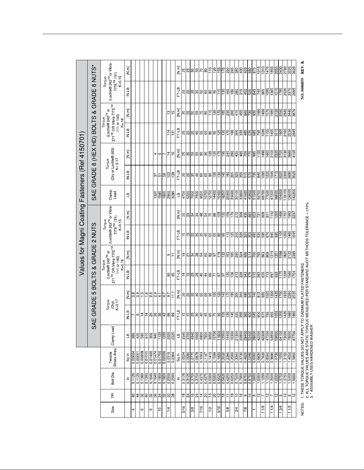
1-3. Torque Chart - Sheet 1 of 5 (SAE Fasteners) . . . . . . . . . . . . . . . . . . . . . . . . . . . . . . . . . . . . . . . . . . . . . . . 1-10
1-4. Torque Chart - Sheet 2 of 5 (SAE Fasteners) . . . . . . . . . . . . . . . . . . . . . . . . . . . . . . . . . . . . . . . . . . . . . . . 1-11
1-5. Torque Chart - Sheet 3 of 5 (SAE Fasteners) . . . . . . . . . . . . . . . . . . . . . . . . . . . . . . . . . . . . . . . . . . . . . . . 1-12
1-6. Torque Chart - Sheet 4 of 5 (METRIC Fasteners) . . . . . . . . . . . . . . . . . . . . . . . . . . . . . . . . . . . . . . . . . . . 1-13
1-7. Torque Chart - Sheet 5 of 5 (METRIC Fasteners) . . . . . . . . . . . . . . . . . . . . . . . . . . . . . . . . . . . . . . . . . . . 1-14
2-1. Machine Component Locations . . . . . . . . . . . . . . . . . . . . . . . . . . . . . . . . . . . . . . . . . . . . . . . . . . . . . . . . . . . 2-6
2-2. Scissor Arm - Safety Prop . . . . . . . . . . . . . . . . . . . . . . . . . . . . . . . . . . . . . . . . . . . . . . . . . . . . . . . . . . . . . . . . . 2-6
2-3. Scissor Arm - Safety Prop . . . . . . . . . . . . . . . . . . . . . . . . . . . . . . . . . . . . . . . . . . . . . . . . . . . . . . . . . . . . . . . . . 2-7
2-4. Hydraulic Oil Check Procedure . . . . . . . . . . . . . . . . . . . . . . . . . . . . . . . . . . . . . . . . . . . . . . . . . . . . . . . . . . . . 2-7
2-5. Hydraulic Oil Fill Procedure . . . . . . . . . . . . . . . . . . . . . . . . . . . . . . . . . . . . . . . . . . . . . . . . . . . . . . . . . . . . . . . 2-7
3-1. Components Mounded on Side Swing - Out Compartment Doors . . . . . . . . . . . . . . . . . . . . . . . . . . 3-1
3-2. Side Swing - Out Compartment Door Installation . . . . . . . . . . . . . . . . . . . . . . . . . . . . . . . . . . . . . . . . . . 3-1
3-3. Battery Cable Connections . . . . . . . . . . . . . . . . . . . . . . . . . . . . . . . . . . . . . . . . . . . . . . . . . . . . . . . . . . . . . . . . 3-2
3-4. Battery Fluid Level. . . . . . . . . . . . . . . . . . . . . . . . . . . . . . . . . . . . . . . . . . . . . . . . . . . . . . . . . . . . . . . . . . . . . . . . 3-3
3-5. DC/AC Power Inverter - Installation . . . . . . . . . . . . . . . . . . . . . . . . . . . . . . . . . . . . . . . . . . . . . . . . . . . . . . . 3-9
3-6. Logic Module Components . . . . . . . . . . . . . . . . . . . . . . . . . . . . . . . . . . . . . . . . . . . . . . . . . . . . . . . . . . . . . . 3-10
3-7. Logic Module CO01 - Harness Connector Identification . . . . . . . . . . . . . . . . . . . . . . . . . . . . . . . . . . . 3-10
3-8. Main Power Contactor Relay and Pump Controller Module Location . . . . . . . . . . . . . . . . . . . . . . 3-11
3-9. Hydraulic Pump Control - Power Connections . . . . . . . . . . . . . . . . . . . . . . . . . . . . . . . . . . . . . . . . . . . . 3-13
3-10. Ground Control Station - Folding Cover . . . . . . . . . . . . . . . . . . . . . . . . . . . . . . . . . . . . . . . . . . . . . . . . . . 3-14
3-11. Ground Control Station Removal. . . . . . . . . . . . . . . . . . . . . . . . . . . . . . . . . . . . . . . . . . . . . . . . . . . . . . . . . 3-15
3-12. Ground Control Station - Rear of Panel . . . . . . . . . . . . . . . . . . . . . . . . . . . . . . . . . . . . . . . . . . . . . . . . . . . 3-15
3-13. Ground Control Station - Fixed Cover . . . . . . . . . . . . . . . . . . . . . . . . . . . . . . . . . . . . . . . . . . . . . . . . . . . . 3-16
3-14. Ground Control Station Removal. . . . . . . . . . . . . . . . . . . . . . . . . . . . . . . . . . . . . . . . . . . . . . . . . . . . . . . . . 3-17
3-15. Ground Control Station - Rear of Panel . . . . . . . . . . . . . . . . . . . . . . . . . . . . . . . . . . . . . . . . . . . . . . . . . . . 3-17
3-16. Platform Control Station Installation . . . . . . . . . . . . . . . . . . . . . . . . . . . . . . . . . . . . . . . . . . . . . . . . . . . . . 3-19
3-17. Platform Control Station Disassembly . . . . . . . . . . . . . . . . . . . . . . . . . . . . . . . . . . . . . . . . . . . . . . . . . . . . 3-19
3-18. Platform Control Station Components - Internal . . . . . . . . . . . . . . . . . . . . . . . . . . . . . . . . . . . . . . . . . . 3-20
3-19. Joystick . . . . . . . . . . . . . . . . . . . . . . . . . . . . . . . . . . . . . . . . . . . . . . . . . . . . . . . . . . . . . . . . . . . . . . . . . . . . . . . . . 3-21
3-20. Tilt Sensor Installation . . . . . . . . . . . . . . . . . . . . . . . . . . . . . . . . . . . . . . . . . . . . . . . . . . . . . . . . . . . . . . . . . . . 3-22
3-21. Elevation Sensor Location . . . . . . . . . . . . . . . . . . . . . . . . . . . . . . . . . . . . . . . . . . . . . . . . . . . . . . . . . . . . . . . 3-23
3-22. Elevation Sensor Installation . . . . . . . . . . . . . . . . . . . . . . . . . . . . . . . . . . . . . . . . . . . . . . . . . . . . . . . . . . . . . 3-24
3-23. Pot-Hole-Protection Assembly . . . . . . . . . . . . . . . . . . . . . . . . . . . . . . . . . . . . . . . . . . . . . . . . . . . . . . . . . . . 3-25
3-24. Steer and Spindle Assembly Installation . . . . . . . . . . . . . . . . . . . . . . . . . . . . . . . . . . . . . . . . . . . . . . . . . . 3-26
3-25. Drive Motor Cover Installation - Option . . . . . . . . . . . . . . . . . . . . . . . . . . . . . . . . . . . . . . . . . . . . . . . . . . 3-27
3-26. Wheel Installation . . . . . . . . . . . . . . . . . . . . . . . . . . . . . . . . . . . . . . . . . . . . . . . . . . . . . . . . . . . . . . . . . . . . . . . 3-28
3-27. Arms and Platform Positioning with Overhead Support . . . . . . . . . . . . . . . . . . . . . . . . . . . . . . . . . . . 3-30
3-28. Platform Assembly - Installation/Removal . . . . . . . . . . . . . . . . . . . . . . . . . . . . . . . . . . . . . . . . . . . . . . . . 3-31
3-29. Scissor Arm Assembly . . . . . . . . . . . . . . . . . . . . . . . . . . . . . . . . . . . . . . . . . . . . . . . . . . . . . . . . . . . . . . . . . . . 3-32
3-30. Scissor Arm Assembly - Pin Configuration . . . . . . . . . . . . . . . . . . . . . . . . . . . . . . . . . . . . . . . . . . . . . . . . 3-33
3-31. Scissor Arm Assembly - Cable Routing. . . . . . . . . . . . . . . . . . . . . . . . . . . . . . . . . . . . . . . . . . . . . . . . . . . . 3-34
3-32. Scissor Arm Assembly - Cable Routing (FTSW) . . . . . . . . . . . . . . . . . . . . . . . . . . . . . . . . . . . . . . . . . . . . 3-35
3-33. Scissor Arm Assembly - Cable Routing (Coiled) . . . . . . . . . . . . . . . . . . . . . . . . . . . . . . . . . . . . . . . . . . . 3-36
3-34. Scissor Arm Assembly - Cable Routing (Coiled) (FTSW) . . . . . . . . . . . . . . . . . . . . . . . . . . . . . . . . . . . .3-37
4-1. Hydraulic Tank Installation . . . . . . . . . . . . . . . . . . . . . . . . . . . . . . . . . . . . . . . . . . . . . . . . . . . . . . . . . . . . . . . . 4-4
4-2. Hydraulic Oil Check Procedure . . . . . . . . . . . . . . . . . . . . . . . . . . . . . . . . . . . . . . . . . . . . . . . . . . . . . . . . . . . . 4-5
4-3. Hydraulic Oil Fill Procedure . . . . . . . . . . . . . . . . . . . . . . . . . . . . . . . . . . . . . . . . . . . . . . . . . . . . . . . . . . . . . . . 4-5
4-4. Hydraulic Pump - Motor Components . . . . . . . . . . . . . . . . . . . . . . . . . . . . . . . . . . . . . . . . . . . . .
4-5. Hydraulic Pump - Motor Components . . . . . . . . . . . . . . . . . . . . . . . . . . . . . . . . . . . . . . . . . . . . . . . . . . . . . 4-7
4-6. Hydraulic Manifold Assembly - Installation . . . . . . . . . . . . . . . . . . . . . . . . . . . . . . . . . . . . . . . . . . . . . . . . 4-8
4-7. Hydraulic Manifold Assembly - Schematic . . . . . . . . . . . . . . . . . . . . . . . . . . . . . . . . . . . . . . . . . . . . . . . . . 4-8
4-8. Hydraulic Manifold Assembly - Component Location . . . . . . . . . . . . . . . . . . . . . . . . . . . . . . . . . . . . . . 4-9
TABLE OF CONTENTS
. . . . . . . . 4-6
3121761 v
Page 10

TABLE OF CONTENTS
4-9. Hydraulic Manifold Assembly - Component Torque. . . . . . . . . . . . . . . . . . . . . . . . . . . . . . . . . . . . . . . 4-10
4-10. Hydraulic Hose Routing . . . . . . . . . . . . . . . . . . . . . . . . . . . . . . . . . . . . . . . . . . . . . . . . . . . . . . . . . . . . . . . . . 4-11
4-11. Drive Motor - Installation . . . . . . . . . . . . . . . . . . . . . . . . . . . . . . . . . . . . . . . . . . . . . . . . . . . . . . . . . . . . . . . . 4-12
4-12. Rear Hydraulic Brake - Installation. . . . . . . . . . . . . . . . . . . . . . . . . . . . . . . . . . . . . . . . . . . . . . . . . . . . . . . . 4-13
4-13. Hydraulic Brakes - Manual Disengage . . . . . . . . . . . . . . . . . . . . . . . . . . . . . . . . . . . . . . . . . . . . . . . . . . . . 4-13
4-14. Lift Cylinder - Lower . . . . . . . . . . . . . . . . . . . . . . . . . . . . . . . . . . . . . . . . . . . . . . . . . . . . . . . . . . . . . . . . . . . . . 4-17
4-15. Lift Cylinder - Upper . . . . . . . . . . . . . . . . . . . . . . . . . . . . . . . . . . . . . . . . . . . . . . . . . . . . . . . . . . . . . . . . . . . . . 4-18
4-16. Steer Cylinder . . . . . . . . . . . . . . . . . . . . . . . . . . . . . . . . . . . . . . . . . . . . . . . . . . . . . . . . . . . . . . . . . . . . . . . . . . . 4-19
4-17. Cylinder Barrel Support. . . . . . . . . . . . . . . . . . . . . . . . . . . . . . . . . . . . . . . . . . . . . . . . . . . . . . . . . . . . . . . . . . 4-20
4-18. Cylinder Rod Support. . . . . . . . . . . . . . . . . . . . . . . . . . . . . . . . . . . . . . . . . . . . . . . . . . . . . . . . . . . . . . . . . . . . 4-20
4-19. Gar-Max Bearing Installation . . . . . . . . . . . . . . . . . . . . . . . . . . . . . . . . . . . . . . . . . . . . . . . . . . . . . . . . . . . . . 4-21
4-20. Rod Seal Installation . . . . . . . . . . . . . . . . . . . . . . . . . . . . . . . . . . . . . . . . . . . . . . . . . . . . . . . . . . . . . . . . . . . . . 4-21
4-21. Poly-Pak Piston Seal Installation . . . . . . . . . . . . . . . . . . . . . . . . . . . . . . . . . . . . . . . . . . . . . . . . . . . . . . . . . 4-22
4-22. Wiper Seal Installation . . . . . . . . . . . . . . . . . . . . . . . . . . . . . . . . . . . . . . . . . . . . . . . . . . . . . . . . . . . . . . . . . . . 4-22
4-23. Installation of Head Seal Kit . . . . . . . . . . . . . . . . . . . . . . . . . . . . . . . . . . . . . . . . . . . . . . . . . . . . . . . . . . . . . . 4-22
4-24. Rod Assembly Installation . . . . . . . . . . . . . . . . . . . . . . . . . . . . . . . . . . . . . . . . . . . . . . . . . . . . . . . . . . . . . . . 4-23
5-1. Hand Held Analyzer . . . . . . . . . . . . . . . . . . . . . . . . . . . . . . . . . . . . . . . . . . . . . . . . . . . . . . . . . . . . . . . . . . . . . . 5-1
5-2. Diagnostic Port Location . . . . . . . . . . . . . . . . . . . . . . . . . . . . . . . . . . . . . . . . . . . . . . . . . . . . . . . . . . . . . . . . . 5-2
5-3. Analyzer Menu - Help and Diagnostics . . . . . . . . . . . . . . . . . . . . . . . . . . . . . . . . . . . . . . . . . . . . . . . . . . . . 5-8
5-4. Analyzer Menu - System Test and Access Level . . . . . . . . . . . . . . . . . . . . . . . . . . . . . . . . . . . . . . . . . . . . 5-9
5-5. Analyzer Menu - Personalities and Machine Setup . . . . . . . . . . . . . . . . . . . . . . . . . . . . . . . . . . . . . . . . 5-10
5-6. Analyzer Menu - Calibrations and Service Mode . . . . . . . . . . . . . . . . . . . . . . . . . . . . . . . . . . . . . . . . . . 5-11
6-1. LSS Component Locations . . . . . . . . . . . . . . . . . . . . . . . . . . . . . . . . . . . . . . . . . . . . . . . . . . . . . . . . . . . . . . . . 6-2
8-1. Voltage Measurement (DC) . . . . . . . . . . . . . . . . . . . . . . . . . . . . . . . . . . . . . . . . . . . . . . . . . . . . . . . . . . . . . . . 8-2
8-2. Resistance Measurement . . . . . . . . . . . . . . . . . . . . . . . . . . . . . . . . . . . . . . . . . . . . . . . . . . . . . . . . . . . . . . . . . 8-2
8-3. Continuity Measurement . . . . . . . . . . . . . . . . . . . . . . . . . . . . . . . . . . . . . . . . . . . . . . . . . . . . . . . . . . . . . . . . . 8-3
8-4. Current Measurement (DC) . . . . . . . . . . . . . . . . . . . . . . . . . . . . . . . . . . . . . . . . . . . . . . . . . . . . . . . . . . . . . . . 8-3
8-5. Application to plug/male connector housing. . . . . . . . . . . . . . . . . . . . . . . . . . . . . . . . . . . . . . . . . . . . . . 8-6
8-6. Use of Seal Plugs . . . . . . . . . . . . . . . . . . . . . . . . . . . . . . . . . . . . . . . . . . . . . . . . . . . . . . . . . . . . . . . . . . . . . . . . . 8-7
8-7. Brad-Harrison M12 – No Dielectric Grease . . . . . . . . . . . . . . . . . . . . . . . . . . . . . . . . . . . . . . . . . . . . . . . . . 8-8
8-8. Phoenix Contact M12 – No Dielectric Grease . . . . . . . . . . . . . . . . . . . . . . . . . . . . . . . . . . . . . . . . . . . . . . 8-9
8-9. AMP Connector . . . . . . . . . . . . . . . . . . . . . . . . . . . . . . . . . . . . . . . . . . . . . . . . . . . . . . . . . . . . . . . . . . . . . . . . . 8-11
8-10. Connector Assembly (1 of 4) . . . . . . . . . . . . . . . . . . . . . . . . . . . . . . . . . . . . . . . . . . . . . . . . . . . . . . . . . . . . . 8-12
8-11. Connector Assembly (2 of 4) . . . . . . . . . . . . . . . . . . . . . . . . . . . . . . . . . . . . . . . . . . . . . . . . . . . . . . . . . . . . . 8-12
8-12. Connector Assembly (3 of 4) . . . . . . . . . . . . . . . . . . . . . . . . . . . . . . . . . . . . . . . . . . . . . . . . . . . . . . . . . . . . . 8-13
8-13. Connector Assembly (4 of 4) . . . . . . . . . . . . . . . . . . . . . . . . . . . . . . . . . . . . . . . . . . . . . . . . . . . . . . . . . . . . . 8-13
8-14. Connector Disassembly. . . . . . . . . . . . . . . . . . . . . . . . . . . . . . . . . . . . . . . . . . . . . . . . . . . . . . . . . . . . . . . . . . 8-14
8-15. Connector Installation . . . . . . . . . . . . . . . . . . . . . . . . . . . . . . . . . . . . . . . . . . . . . . . . . . . . . . . . . . . . . . . . . . . 8-15
8-16. DT/DTP Contact Installation . . . . . . . . . . . . . . . . . . . . . . . . . . . . . . . . . . . . . . . . . . . . . . . . . . . . . . . . . . . . . 8-16
8-17. DT/DTP Contact Removal. . . . . . . . . . . . . . . . . . . . . . . . . . . . . . . . . . . . . . . . . . . . . . . . . . . . . . . . . . . . . . . . 8-16
8-18. HD/HDP Contact Installation . . . . . . . . . . . . . . . . . . . . . . . . . . . . . . . . . . . . . . . . . . . . . . . . . . . . . . . . . . . . . 8-16
8-19. HD/HDP Locking Contacts Into Position . . . . . . . . . . . . . . . . . . . . . . . . . . . . . . . . . . . . . . . . . . . . . . . . . . 8-17
8-20. HD/HDP Contact Removal . . . . . . . . . . . . . . . . . . . . . . . . . . . . . . . . . . . . . . . . . . . . . . . . . . . . . . . . . . . . . . . 8-17
8-21. HD/HDP Unlocking Contacts. . . . . . . . . . . . . . . . . . . . . . . . . . . . . . . . . . . . . . . . . . . . . . . . . . . . . . . . . . . . . 8-17
8-22. Electrical Schematic . . . . . . . . . . . . . . . . . . . . . . . . . . . . . . . . . . . . . . . . . . . . . . . . . . . . . . . . . . . . . . . . . . . . . 8-20
8-23. Hydraulic Schematic. . . . . . . . . . . . . . . . . . . . . . . . . . . . . . . . . . . . . . . . . . . . . . . . . . . . . . . . . . . . . . . . . . . . . 8-32
vi 3121761
Page 11

LIST OF TABLES
TABLE NO. TITLE PAGE NO.
1-1 Operating Specifications. . . . . . . . . . . . . . . . . . . . . . . . . . . . . . . . . . . . . . . . . . . . . . . . . . . . . . . . . . . . . . . . . . 1-1
1-2 Platform Capacities . . . . . . . . . . . . . . . . . . . . . . . . . . . . . . . . . . . . . . . . . . . . . . . . . . . . . . . . . . . . . . . . . . . . . . . 1-2
1-3 Dimensions . . . . . . . . . . . . . . . . . . . . . . . . . . . . . . . . . . . . . . . . . . . . . . . . . . . . . . . . . . . . . . . . . . . . . . . . . . . . . . 1-2
1-4 Tire Specifications . . . . . . . . . . . . . . . . . . . . . . . . . . . . . . . . . . . . . . . . . . . . . . . . . . . . . . . . . . . . . . . . . . . . . . . . 1-2
1-5 OEM Battery Specifications . . . . . . . . . . . . . . . . . . . . . . . . . . . . . . . . . . . . . . . . . . . . . . . . . . . . . . . . . . . . . . . 1-3
1-6 Battery Charger Specifications . . . . . . . . . . . . . . . . . . . . . . . . . . . . . . . . . . . . . . . . . . . . . . . . . . . . . . . . . . . . 1-4
1-7 Tilt Activation Setting. . . . . . . . . . . . . . . . . . . . . . . . . . . . . . . . . . . . . . . . . . . . . . . . . . . . . . . . . . . . . . . . . . . . . 1-5
1-8 High Drive Cutout Height . . . . . . . . . . . . . . . . . . . . . . . . . . . . . . . . . . . . . . . . . . . . . . . . . . . . . . . . . . . . . . . . . 1-5
1-9 Capacities . . . . . . . . . . . . . . . . . . . . . . . . . . . . . . . . . . . . . . . . . . . . . . . . . . . . . . . . . . . . . . . . . . . . . . . . . . . . . . . . 1-5
1-10 Hydraulic Oil . . . . . . . . . . . . . . . . . . . . . . . . . . . . . . . . . . . . . . . . . . . . . . . . . . . . . . . . . . . . . . . . . . . . . . . . . . . . . 1-5
1-11 Lubrication Specifications . . . . . . . . . . . . . . . . . . . . . . . . . . . . . . . . . . . . . . . . . . . . . . . . . . . . . . . . . . . . . . . . 1-6
1-12 Mobilfluid 424 Specs . . . . . . . . . . . . . . . . . . . . . . . . . . . . . . . . . . . . . . . . . . . . . . . . . . . . . . . . . . . . . . . . . . . . . 1-6
1-13 Mobil DTE 10 Excel 15 Specs . . . . . . . . . . . . . . . . . . . . . . . . . . . . . . . . . . . . . . . . . . . . . . . . . . . . . . . . . . . . . . 1-6
1-14 Biodegradable Hydraulic Fluid Specs. . . . . . . . . . . . . . . . . . . . . . . . . . . . . . . . . . . . . . . . . . . . . . . . . . . . . . 1-6
1-15 Hydraulic Pressure Settings . . . . . . . . . . . . . . . . . . . . . . . . . . . . . . . . . . . . . . . . . . . . . . . . . . . . . . . . . . . . . . . 1-8
1-16 Hydraulic Cylinder Specifications . . . . . . . . . . . . . . . . . . . . . . . . . . . . . . . . . . . . . . . . . . . . . . . . . . . . . . . . . 1-8
1-17 Critical Stability Weights . . . . . . . . . . . . . . . . . . . . . . . . . . . . . . . . . . . . . . . . . . . . . . . . . . . . . . . . . . . . . . . . . . 1-9
1-18 Major Component Weights . . . . . . . . . . . . . . . . . . . . . . . . . . . . . . . . . . . . . . . . . . . . . . . . . . . . . . . . . . . . . . . 1-9
2-1 Inspection and Maintenance Responsibilities. . . . . . . . . . . . . . . . . . . . . . . . . . . . . . . . . . . . . . . . . . . . . . 2-2
2-2 Preventive Maintenance & Inspection Schedule . . . . . . . . . . . . . . . . . . . . . . . . . . . . . . . . . . . . . . . . . . . 2-4
2-3 Cylinder Drift . . . . . . . . . . . . . . . . . . . . . . . . . . . . . . . . . . . . . . . . . . . . . . . . . . . . . . . . . . . . . . . . . . . . . . . . . . . . 2-10
3-1 Battery Charger Specifications . . . . . . . . . . . . . . . . . . . . . . . . . . . . . . . . . . . . . . . . . . . . . . . . . . . . . . . . . . . . 3-5
3-2 Diagnostic Trouble Codes (Delta Q Battery Charger) . . . . . . . . . . . . . . . . . . . . . . . . . . . . . . . . . . . . . . . 3-6
3-3 Fault Codes (Green Power). . . . . . . . . . . . . . . . . . . . . . . . . . . . . . . . . . . . . . . . . . . . . . . . . . . . . . . . . . . . . . . . 3-7
3-4 Fault Codes (Eagle Battery Charger) . . . . . . . . . . . . . . . . . . . . . . . . . . . . . . . . . . . . . . . . . . . . . . . . . . . . . . . 3-8
3-5 Pump Control Module Specifications. . . . . . . . . . . . . . . . . . . . . . . . . . . . . . . . . . . . . . . . . . . . . . . . . . . . . 3-12
3-6 Pump Power Module Terminal Functions (CO117-J1) . . . . . . . . . . . . . . . . . . . . . . . . . . . . . . . . . . . . . 3-12
3-7 Joystick Specifications . . . . . . . . . . . . . . . . . . . . . . . . . . . . . . . . . . . . . . . . . . . . . . . . . . . . . . . . . . . . . . . . . . . 3-21
3-8 Connector Chart. . . . . . . . . . . . . . . . . . . . . . . . . . . . . . . . . . . . . . . . . . . . . . . . . . . . . . . . . . . . . . . . . . . . . . . . . 3-21
3-9 Tilt Sensor Wiring Pin Assignment. . . . . . . . . . . . . . . . . . . . . . . . . . . . . . . . . . . . . . . . . . . . . . . . . . . . . . . . 3-22
5-1 Machine Configuration Programming Information . . . . . . . . . . . . . . . . . . . . . . . . . . . . . . . . . . . . . . . 5-12
5-2 Machine Model Adjustment (Personality Settings) . . . . . . . . . . . . . . . . . . . . . . . . . . . . . . . . . . . . . . . .5-13
6-1 Personalities Menu Description . . . . . . . . . . . . . . . . . . . . . . . . . . . . . . . . . . . . . . . . . . . . . . . . . . . . . . . . . . . 6-3
6-2 Diagnostic Menu Descriptions . . . . . . . . . . . . . . . . . . . . . . . . . . . . . . . . . . . . . . . . . . . . . . . . . . . . . . . . . . . . 6-3
6-3 Calibrations Menu . . . . . . . . . . . . . . . . . . . . . . . . . . . . . . . . . . . . . . . . . . . . . . . . . . . . . . . . . . . . . . . . . . . . . . . . 6-5
6-4 Platform 110% Calibration Weight . . . . . . . . . . . . . . . . . . . . . . . . . . . . . . . . . . . . . . . . . . . . . . . . . . . . . . . . 6-6
6-5 Platform 100% Calibration Weight . . . . . . . . . . . . . . . . . . . . . . . . . . . . . . . . . . . . . . . . . . . . . . . . . . . . . . . . 6-7
6-6 Platform 120% Calibration Weight . . . . . . . . . . . . . . . . . . . . . . . . . . . . . . . . . . . . . . . . . . . . . . . . . . . . . . . . 6-7
6-7 LSS Troubleshooting . . . . . . . . . . . . . . . . . . . . . . . . . . . . . . . . . . . . . . . . . . . . . . . . . . . . . . . . . . . . . . . . . . . . . 6-9
7-1 Diagnostic Trouble Codes (DTC) . . . . . . . . . . . . . . . . . . . . . . . . . . . . . . . . . . . . . . . . . . . . . . . . . . . . . . . . . . 7-2
TABLE OF CONTENTS
3121761 vii
Page 12

TABLE OF CONTENTS
This page left blank intentionally
viii 3121761
Page 13

1.1 SPECIFICATION
SECTION 1 - SPECIFICATIONS
SECTION 1. SPECIFICATIONS
Table 1-1. Operating Specifications
DESCRIPTION 4045R
PLATFORM
Maximum Platform Height (Ground to Platform Floor - Elevated) 39 ft. 3 in. (11.9m)
Machine Height (Ground to Top of Rails) 8 ft. 4 in. (2.549m)
Machine Height - Rails Folded (Ground to Top of Folded Rails) 6 ft. 3 in. (1.903m)
Platform L ift Time (se conds/rated l oad)
Lift Up:
Lift Down:
Electronic Arm Guards (Activation Height) 75 in. (190.5 cm)
DRIVING
Ma x i m um O p er a ti n g Sl o p e F ro n t t o B ac k :
(platform fully elevated) S i d e t o S id e :
M ax i m u m D r i ve S p e e d (F W D / R E V ) St o w e d :
( S e c o n d s t o D r i v e 2 5 f t ( 7 . 6 2 m ) E l e v a t e d :
Elevated Drive Height
Indoor:
Outdoor - ANSI/CE/CSA/GB:
AUS:
Tur n in g Ra d iu s
Inside:
(C ur b to Cu r b) Ou t si d e:
CHASSIS
Approximate Gross Machine Weight
ANSI/CE/CSA/GB:
AUS:
Wheelbase 80 in. (2.032m)
Machine Overall Width 45 in. (1.143m)
Maximum Tire Load (per wheel) 2,680 lb. (1216 kg)
Ground Bearing Pressure 137 psi (943 kPa)
Gr o un d Cl ea r an ce
PHP Retracted:
PHP Deployed:
Break Over Angle (Grade) 14.5° (26%)
Ma x im u m H yd r au l ic Pr e ss ur e
Main Relief:
Steer Relief:
Lift Relief:
ANSI/CSA/CE/AUS/GB
73 Seconds
48 Seconds
3.5°
1.5°
8 seconds (2.0 mph (3.4 kph)
34 seconds (0.5 mph (0.8 kph)
39 ft. (11.9 m)
28.7 ft. (8.75 m)
39 ft. (11.9 m)
0 in. (0 cm)
92 in. (233.68 cm)
7,000 lb. (3175 kg)
7,525 lb. (3413 kg)
5 in. (126 mm)
1.26 in. (32 mm)
3000 psi (207 bar)
1250 psi (86 bar)
2500 psi (172 bar)
3121761 1-1
Page 14
SECTION 1 - SPECIFICATIONS
Platform Capacities
Table 1-2. Platform Capacities
MAXIMUM
MAXIMUM
SPECIFICATION
ANSI/CSA/CE/AUS/GB FULL
ANSI/CSA/CE/AUS/GB 29 ft (8.8 m)
AUS FULL
NOTE: (1) Maximum Platform Capacity includes platform and platform extension.
(2) INDOOR USE is use of a MEWP in areas shielded from wind so that there is no wind. OUTDOOR USE is use of a MEWP
in an environment that can be exposed to wind.
OPERATING
HEIGHT
MAXIMUM
PLATFORM
CAPACITY
770 lb. (350 Kg)
550 lb. (249 Kg) 1 Person + 371 lb. (169 Kg)
300 lb. (136 Kg) 1 Person + 124 lb. (56 Kg)
CAPACITY
ALLOWED ON
(1)
PLATFORM
EXTENSION
250 lb. (113 Kg)
MAXIMUM PERSONS
ALLOWED IN PLATFORM
3 Persons + 242 lb. (110 Kg)
MAX. SIDE FORCE
(Platform Fully
@ Max. Capacity)
Machine Dimensional Data Tires
Table 1-3. Dimensions
DESCRIPTION 4045R
Platform Height - Elevated
(Ground to Platform Floor)
Platform Height - Stowed
(Ground to Platform Floor)
Rail Height
(Platform Floor to Top of Rail)
39 ft. 3 in. (12 m)
55 in. (140 cm)
44 in. (111.76 cm)-
Folding Rail
Size
Wheel Nut Torque
(1-1/8 inch - Slotted Nut with Cotter Pin)
Table 1-4. Tire Specifications
DESCRIPTION 4045R
MAXIMUM
Extended
90 lb. (400 N) 0 mph (0 m/s) INDOOR
45 lb. (200 N) 28 mph (12.5 m/s) OUTDOOR
OPERATING
WIND SPEED
ENVIRONMENT
16 in. x 5 in.
(40.6 cm x12.7 cm)
150 ft. lbs. (203 Nm)
(2)
Overall Height
(Ground to Top Rail):
(Rails Folded Down):
Overall Machine Width 45 in. (114.3 cm)
Overall Machine Length
(w/ladder)
Platform Size - Length (Inside) 96 in. (243.84 cm)
Platform Size - Width (Inside) 41 in. (104.14 cm)
Wheelbase 80 in. (203.2 cm)
100 in. (254 cm)
76.8 in. (192.4 cm)
106 in. (269.24 cm)
1-2 3121761
Page 15

Batteries
NOTICE
SECTION 1 - SPECIFICATIONS
Table 1-5. OEM Battery Specifications
DESCRIPTION Lead Acid AGM
Voltage (24V System - Series) 12V per battery
Amp Hour Rating 150 AH @ 20 HR rate 185 AH @ 20 HR rate 150 AH @ 20 HR rate
Reserve Capacity 280 Minutes @ 25Amps 324 Minutes @ 25Amps 320 Minutes @ 25Amps
Weight (each battery) 82 lb. (37 kg) 106 lb. (48 kg) 88 lb. (40 kg)
Motors
JLG MACHINES EQUIPPED WITH DELTA Q BATTERY CHARGERS ARE
DESIGNED FOR THE BEST PERFORMANCE WITH OEM FACTORY APPROVED
BATTERIES.
APPROVED JLG REPLACEMENT BATTERIES ARE AVAILABLE THROUGH
JLG’S AFTERMARKET PARTS DISTRIBUTION CENTERS OR JLG'S AFTERMARKET PROGRAMS. FOR ASSISTANCE WITH PROPER BATTERY REPLACEMENT, PLEASE CONTACT YOUR LOCAL JLG SUPPORT OFFICE.
BATTERIES APPROVED BY JLG HAVE BEEN TESTED FOR COMPATIBILITY
WITH THE ALGORITHM PROGRAMMING OF THE DELTA Q BATTERY CHARGER TO OPTIMIZE BATTERY LIFE AND MACHINE CYCLE TIMES. THE USE OF
NON APPROVED BATTERIES IN YOUR JLG EQUIPMENT MAY RESULT IN
PERFORMANCE ISSUES OR BATTERY CHARGER FAULT CODES. JLG
ASSUMES NO RESPONSIBILITY FOR SERVICE OR PERFORMANCE ISSUES
ARISING FROM THE USE OF NON APPROVED BATTERIES.
• Drive Motors
Type: Hydraulic
Displacement: 364 cc/rev (22.2 in
Torque: at 100 psi, 4.2 gpm 2700 in. lbs.
(305.1 Nm)
at 3000 psi, 2.2 gpm 8500 in. lbs.
(960.4 Nm)
Max. Power: 45 hp (34 kW)
Max. Oil Flow: 18 gpm (68 Lpm) - Continuous
•Hydraulic Brake
Type: Hydraulic Release
Holding Torque: 10,000 in. lbs. (1130 Nm)
Max. Speed: 250 rpm
Release Pressure: 406 psi (28 bar)
Max Release Pressure: 3000 psi (207 bar)
Release Volume: 0.7 cu. in. (11.5 cc)
• Hydraulic Pump/Electric Motor
Motor Type: 24V DC Wound Field
Motor Power: 4.5 kW
Pump Displacement: 0.29 in. /rev (4.77cc/rev)
Pump Pressure: 2100 psi Continuous
3500 psi Intermittent
3
/rev)
3121761 1-3
Page 16

SECTION 1 - SPECIFICATIONS
Electrical System
Table 1-6. Battery Charger Specifications
DESCRIPTION ALL MACHINES
Electrical System Voltage (DC) 24V
Battery Charger:
Input:
AC Inp ut Volta ge:
Nominal AC Input Voltage:
Input Frequency:
Max. AC Input Current:
Ingress Protection:
Operating Temperature:
Output:
Nominal DC Output Voltage:
Max. DC Output Voltage:
Max DC Output Current:
Max. Interlock Current:
Protection:
Output Reverse Polarity:
Output Short Circuit:
AC Over load:
DC Overload:
Delta-Q
85-270V AC
100VAC / 240VAC RMS
50 - 60Hz
7.5A
IP66 NEMA4 Type 4
-40°F (-40°C) to 149°F (+65°C)
24V
36V
27.1A
1A @ 24V
Electronic Protection - Auto Reset
Curren t Limi ted
Curren t Limi ted
Curren t Limi ted
PRO - Eagle Perf. Series
108-132V AC
120VAC
45 - 65Hz
12A
IP35
-22°F (-30°C) to 122°F (+50°C)
24V
31.92V
25A
1A @ 24V
Electronic Protection-Auto Reset
Electronic Protection-Auto Reset
Branch Circuit Protection
Curren t Limit ed
Green Power - Pylon International
100-240V AC
— —
45 - 65Hz
8.5A
IP66
-4°F (-20°C) to 122°F (+50°C)
24V
34V
30A
1A @ 24V
Electronic Protection-Auto Reset
Electronic Protection-Auto Reset
Curren t Limi ted
Curren t Limi ted
1-4 3121761
Page 17

SECTION 1 - SPECIFICATIONS
1.2 LIMIT SWITCH ACTIVATION
Tilt Alarm
NOTE: When the tilt indicator warning is activated the fol-
lowing functions are affected;
Platform Lowered: Only Drive Allowed.
Platform Raised: Drive and lift up functions are dis-
abled, platform must be fully lowered (stowed) to
drive out of tilt condition.
Table 1-7. Tilt Activation Setting
TILT SETTING
MODEL
4045R 3.5°
Y-Ax is
(front to back)
TILT SETTING
X-Axis
(side to side)
1.50° - outdoor
1.50° - indoor
2.00 ° - outdoor
2.00° - indoor
2.50° - outdoor
2.50° - indoor
Maximum Deck
Elevation
25-28.7 ft
31 ft. - max.
23 - 25 ft.
27 - 31 ft.
0 - 23 ft.
0 - 27 ft.
7.6 - 8.7 m
9.4 - max.
7 - 7.6 m
8.2 - 9.4 m
0 - 7 m
0 - 8.2 m
High Drive Speed Cutout
High drive speed is cut out when the platform is raised
above the preset height per model as follows:
NOTE: These figures are given with a tolerance of ± 12 in.
(0.31 m).
1.3 LUBRICATION
Lubrication Capacities
Table 1-9. Capacities
COMPONENT 4045R
Hydraulic
Reservoir (at Full mark) 6.6 Gal. (25L)
Hydraulic System
(Including
Reservoir)
7.9 Gal. (30 L)
Hydraulic Oil
Table 1-10. Hydraulic Oil
HYDRAULIC SYSTEM OPERATING
TEMPERATURE RANGE
0° F to +23° F (-18° C to -5° C) 10W
0° F to 210° F (-18° C to + 99° C) 10W-20, 10W-30
50° F to 210° F (+10° C to +99° C) 20W-20
NOTE: Aside from JLG recommendations, it is not advisable
to mix oils of different brands or types, as they may
not contain the same required additives or be of
comparable viscosities.
SAE VISCOSITY GRADE
Table 1-8. High Drive Cutout Height
MODEL
4045R 75 in. (190.5 cm)
HIGH DRIVE SPEED
CUTOUT HEIGHT
DRIVE SPEED REDUCTION
2.0 mph (3.2 kph)
to
0.5 mph (0.8 kph)
3121761 1-5
Page 18

SECTION 1 - SPECIFICATIONS
Lubrication Specifications
Table 1-11. Lubrication Specifications
KEY SPECIFICATIONS
MPG Multipurpose Grease having a minimum dripping point of 350° F.
Excellent water resistance and adhesive qualities, and being of
extreme pressure type. (Timken OK 40 pounds minimum.)
EPGL Extreme Pressure Gear Lube (oil) meeting API service classification
GL-5 or MIL-Spec MIL-L-2105.
HO JLG Recommends - Mobil - Mobilfluid 424
Mobil EAL ENVIRONSYN H 32
Mobil SHC HYDRAULIC EAL 32
NOTE: EAL and SHC are compatible with each other.
Table 1-13. Mobil DTE 10 Excel 15 Specs
ISO Viscosity Grade 15
Pour Po int, °C Max. -54
Flash Point, °C Min. 182
Viscosity
cSt @ 40° C 15.8
cSt @ 100° C 4.07
cSt @ 100° F 15.8
cSt @ 212° F 4.07
Visco sit y In dex 168
Density (Kg/l) @ 15°C 0.8375
Density (lb/in³) @ 60°F 0.0302
Table 1-12. Mobilfluid 424 Specs
Inspection Data Recommended Optional
ISO Viscosity Grade 10W-30 10W-20
Spec Gravity API 29.0 29.3
Density, LB/GAL, 60° F 7.35 7.3
Flash Point, ° F(° C) 442(228) 380(193)
Pour Point, ° F(° C) -46 (-43) -30(-34)
Viscosity
Brookfield, cP at -18° C 2700
Brookfield, cP at 0° F 2500
Viscosity, cST at 40°C 55 52.1
Viscosity, cST at 100°C 9.3 8.95
Visco sit y In dex 152 152
Viscosity, Sus at 100°F 26.0
Viscosity, Sus at 210°F 56.8
Color, ASTM D 1500 3.0
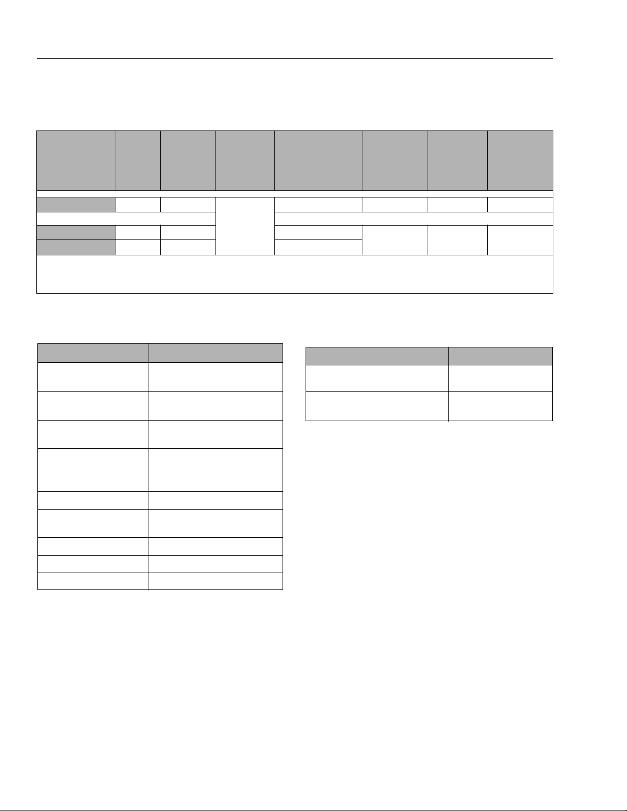
Table 1-14. Biodegradable Hydraulic Fluid Specs
MOBIL EAL
Inspection Data
SAE Grade 32 32
Density @ 15° C
ASTM D 4052, kg/L
Flash Point, ° F(°CF) 514(268) 540(282)
Pour Po int, ° F (° C) -38(-39) -27(-33)
Operating Temp, ° F (° C) -20(-29) to 200(93) 1.4(-17) to 200(93)
Viscosity, cST at 40°C 33.1 31.1
Viscosity, cST at 100°C 6.36 6.2
Visc osit y Ind ex 147 152
ENVIRONSYN
H 32
0.869 0.936
Viscosity
MOBIL SHC
HYDRAULIC
EAL 32
1-6 3121761
Page 19
SECTION 1 - SPECIFICATIONS
1001219909_C
32
15
32
15
147
164
168
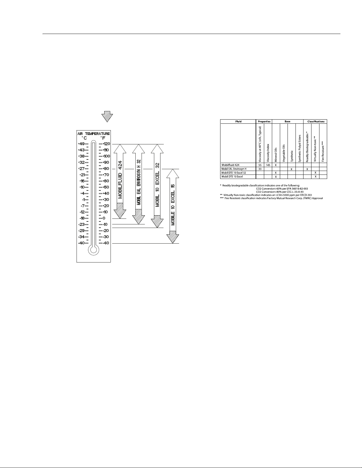
NOTICE:
MACHINE OPERATION USING NON-JLG APPROVED
HYDRAULIC FLUIDS OR OPERATION OUTSIDE OF THE
TEMPERATURE BOUNDARIES OUTLINED IN THE
“HYDRAULIC FLUID OPERATION CHART” MAY RESULT
IN PREMATURE WEAR OR DAMAGE TO COMPONENTS
OF THE HYDRAULIC SYSTEM.
IN THIS REGION FUNCTION SPEEDS
& BATTERY LIFE MAY BE
SIGNIFICANTLY REDUCED
Figure 1-1. Hydraulic Oil Operating Temperature Specifications
Specified lubricants, as recommended by the component
manufacturers, are always the best choice, however, multipurpose greases usually have the qualities which meet a
variety of single purpose grease requirements.
Should any question arise, regarding the use of greases in
maintenance stock, consult your local supplier for evaluation. Refer to Table 1-11, Lubrication Specifications for an
explanation of the lubricant key designations.
3121761 1-7
Page 20

SECTION 1 - SPECIFICATIONS
Serial Number
Plate
Figure 1-2. Serial Number Location
1.4 HYDRAULIC PRESSURE SETTINGS
Table 1-15. Hydraulic Pressure Settings
MODEL MAIN RELIEF LIFT RELIEF STEER RELIEF
4045R
3000 ± 70 psi
(207± 5bar)
2500 ± 70 psi
(172 ± 5 bar)
1.5 HYDRAULIC CYLINDER SPECIFICATIONS
Table 1-16. Hydraulic Cylinder Specifications
DESCRIPTION 4045R
Lift Cylinder Bore Diameter
Upper:
Lower:
Lift Cylinder Stroke
Upper:
Lower:
Lift Cylinder Rod Diameter
Upper:
Lower:
Steer Cylinder Bore Diameter
Steer Cylinder Stroke
(left or right)
Steer Cylinder Rod Diameter
2.56 in.(65 mm)
3.94 in. (100 mm)
54.92 in.(1395 mm)
54.92 in. (1395 mm)
2.2 in.(55 mm)
2.56 in. (65 mm)
2.75 in.
(70 mm)
8.94 in.
(227.1 mm)
1.97 in.
(50mm)
1.6 SERIAL NUMBER LOCATION
For machine identification, a serial number plate is affixed
to the machine. See Figure 1-2.
1250 ± 70 psi
(86 ±5 bar)
1-8 3121761
Page 21
SECTION 1 - SPECIFICATIONS
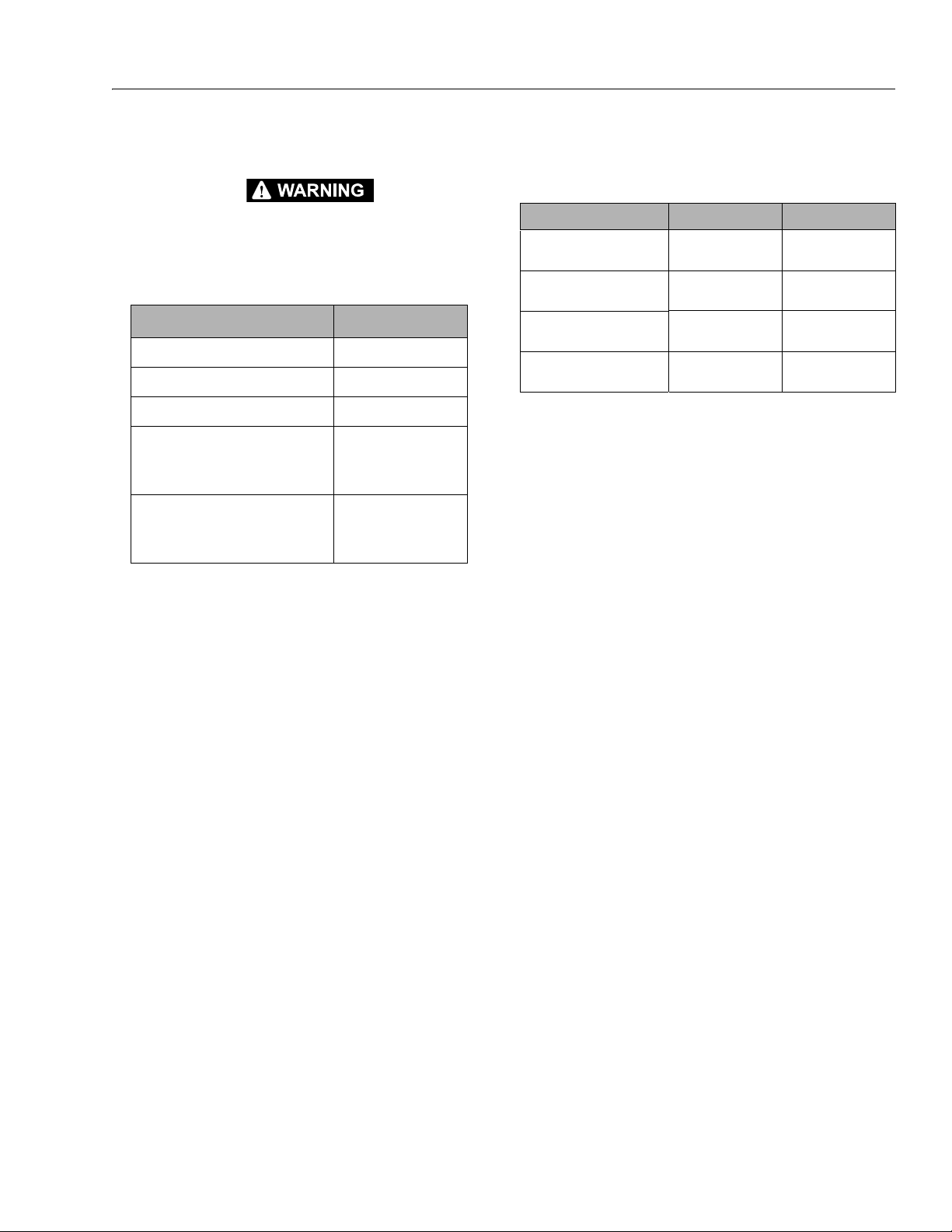
1.7 CRITICAL STABILITY WEIGHTS
DO NOT REPLACE ITEMS CRITICAL TO STABILITY, SUCH AS BATTERIES
OR TIRES, WITH ITEMS OF DIFFERENT WEIGHT OR SPECIFICATION. DO
NOT MODIFY THE MEWP IN ANY WAY TO AFFECT STABILITY.
Table 1-17. Critical Stability Weights
COMPONENT 4045R
Wheel and Tire Assembly (each) 52.7 lb. (23.9 kg)
Wheel/Tire and Drive Assembly (each) 81.1 lb. (36.8 kg)
Wheel/Tire and Brake Assembly (each) 89.7 lb. (40.7 kg)
Batteries (each) Standard:
AGM:
Batteries (combined X4) Standard:
AGM:
82 lb. (37 kg)- 150AH
106 lb. (48 kg) - 185AH
88 lb. (40 kg)
328 lb. (148 kg) - 150AH
424 lb. (192 kg) - 185AH
352 lb. (160 kg)
1.8 MAJOR COMPONENT WEIGHTS
Table 1-18. Major Component Weights
COMPONENT ANSI/CE/CSA/GB AUS
Platform with Rails/Extension
(Rail in Rail)
Platform with Rails/Extension
(Dual Rail)
Arm Assembly (Includes Lift Cylinder)
Chassis w/Wheel/Tire/Steering/PHP and Drive Assembly
524 lb.
(238 Kg)
539 lb.
(244 Kg)
3648 lb.
(1654 Kg)
2778 lb.
(1260 Kg)
524 lb.
(238 Kg)
539 lb.
(244 Kg)
3648 lb.
(1654 Kg)
3298 lb.
(1496 Kg)
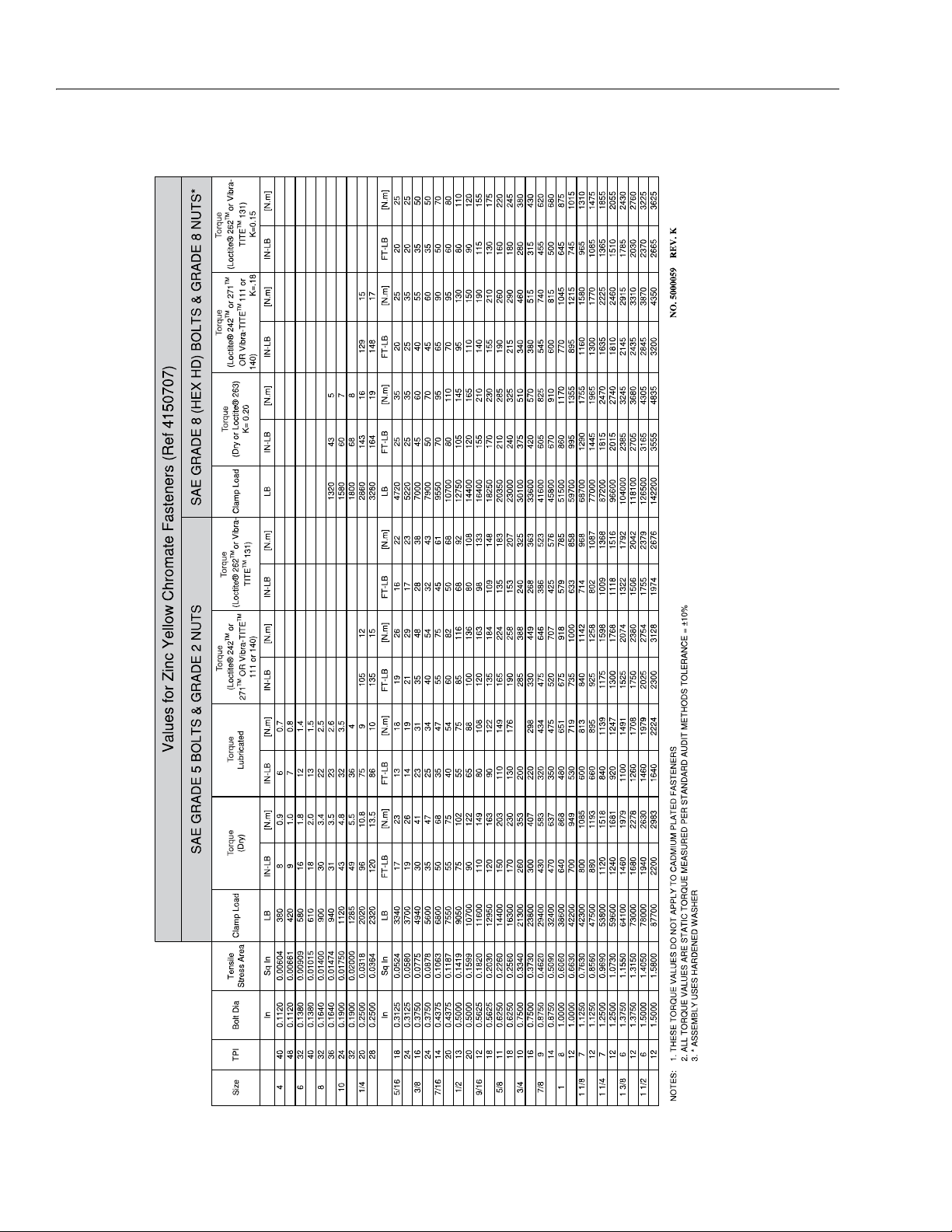
1.9 TORQUE REQUIREMENTS
Self locking fasteners, such as nylon insert and thread
deforming locknuts, are not intended to be reinstalled
after removal. Always use new replacement hardware
when installing locking fasteners.
NOTE: When maintenance becomes necessary or a fas-
tener has loosened, refer to the Torque Charts on
page 1-10 to determine proper torque value.
3121761 1-9
Page 22
SECTION 1 - SPECIFICATIONS
Torque Charts
Figure 1-3. Torque Chart - Sheet 1 of 5 (SAE Fasteners)
1-10 3121761
Page 23
SECTION 1 - SPECIFICATIONS
Figure 1-4. Torque Chart - Sheet 2 of 5 (SAE Fasteners)
3121761 1-11
Page 24
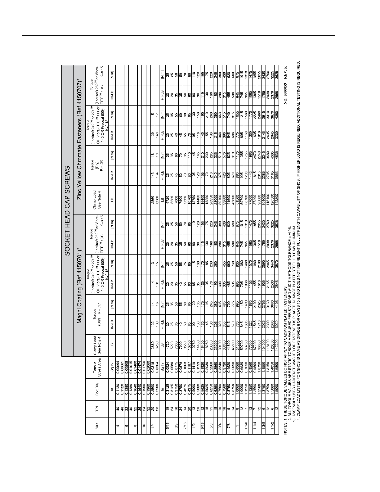
SECTION 1 - SPECIFICATIONS
Figure 1-5. Torque Chart - Sheet 3 of 5 (SAE Fasteners)
1-12 3121761
Page 25
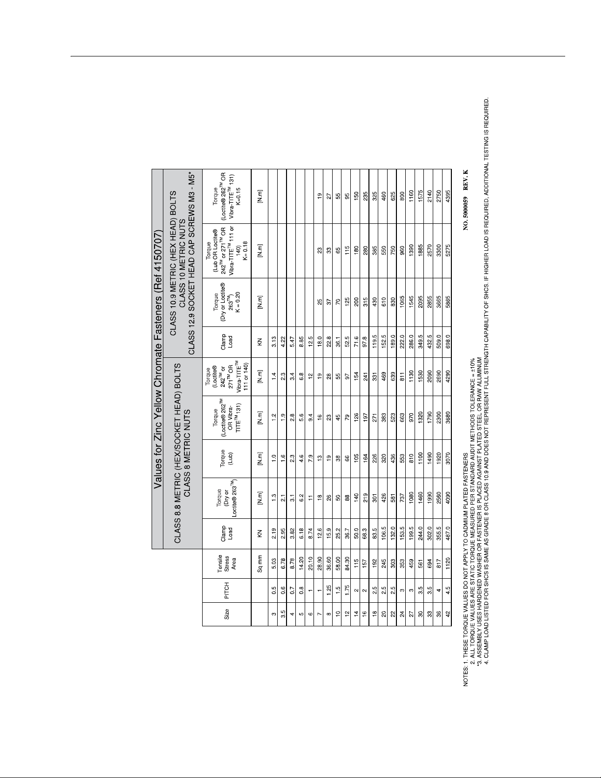
SECTION 1 - SPECIFICATIONS
Figure 1-6. Torque Chart - Sheet 4 of 5 (METRIC Fasteners)
3121761 1-13
Page 26
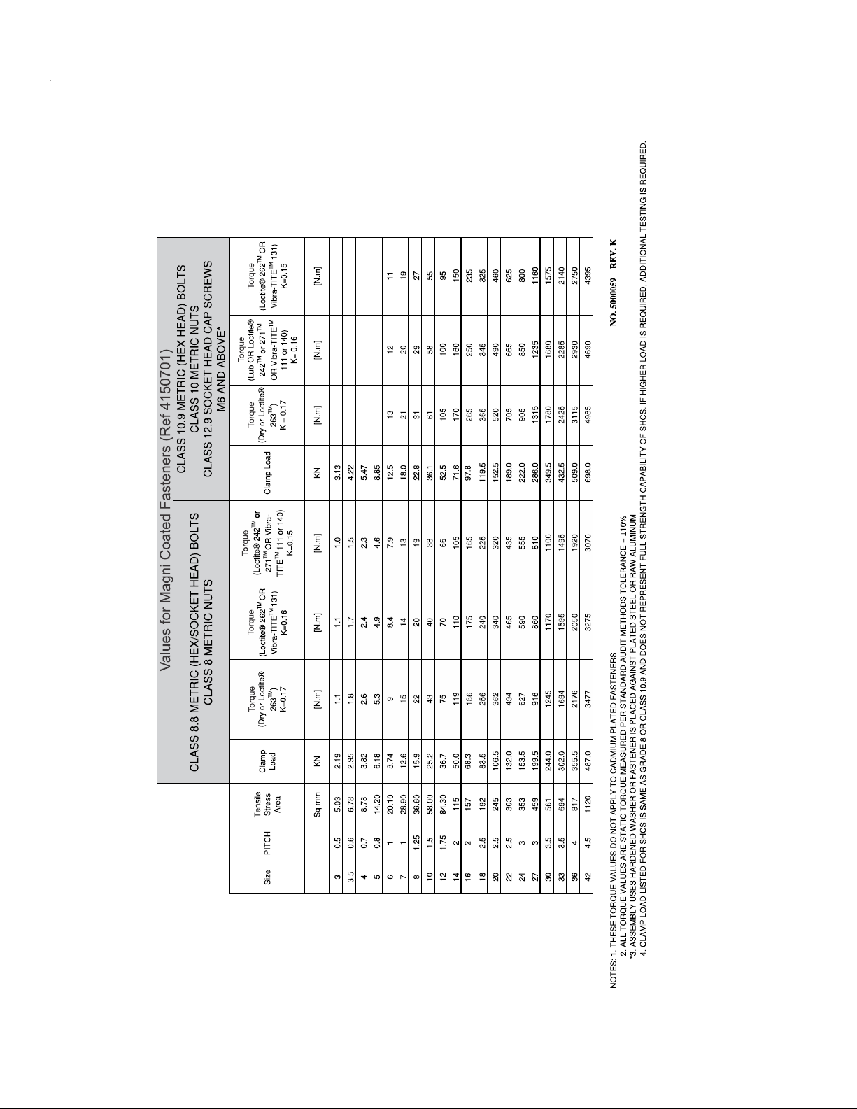
SECTION 1 - SPECIFICATIONS
Figure 1-7. Torque Chart - Sheet 5 of 5 (METRIC Fasteners)
1-14 3121761
Page 27

SECTION 2. GENERAL
SECTION 2 - GENERAL
2.1 MACHINE PREPARATION, INSPECTION, AND MAINTENANCE
General
This section provides the necessary information needed
by those personnel that are responsible to place the
machine in operation readiness and maintain its safe
operating condition. For maximum service life and safe
operation, ensure that all the necessary inspections and
maintenance have been completed before placing the
machine into service. With proper care, maintenance
and inspections performed per JLG's recommendations
with any and all discrepancies corrected, this product
will be fit for continued use.
Preparation, Inspection, and Maintenance
It is important to establish and conform to a comprehensive inspection and preventive maintenance program. The following table outlines the periodic machine
inspections and maintenance recommended by JLG
Industries, Inc. Consult your national, regional, or local
regulations for further requirements for Mobile Elevating Work Platform (MEWP). The frequency of inspections and maintenance must be increased as
environment, severity and frequency of usage requires.
Pre-Start Inspection
It is the User’s or Operator’s primary responsibility to
perform a Pre-Start Inspection of the machine prior to
use daily or at each change of operator. Reference the
Operation and Safety Manual for completion procedures for the Pre-Start Inspection. The Operation and
Safety Manual must be read in its entirety and understood prior to performing the Pre-Start Inspection.
Pre-Delivery Inspection and Frequent Inspection
The Pre-Delivery Inspection and Frequent Inspection
shall be performed by a qualified JLG equipment
mechanic. JLG Industries, Inc. recognizes a qualified JLG
equipment mechanic as a person who, by possession of
a recognized degree, certificate, extensive knowledge,
training, or experience, has successfully demonstrated
the ability and proficiency to service, repair, and maintain the subject JLG product model.
The Pre-Delivery Inspection and Frequent Inspection
procedures are performed in the same manner, but at
different times. The Pre-Delivery Inspection shall be performed prior to each sale, lease, or rental delivery. The
Frequent Inspection shall be accomplished for each
machine in service for 3 months or 150 hours (whichever comes first); out of service for a period of more than
3 months; or when purchased used. The frequency of
this inspection must be increased as environment,
severity and frequency of usage requires.
Reference the JLG Pre-Delivery and Frequent Inspection
Form and the Inspection and Preventative Maintenance
Schedule for items requiring inspection during the performance of these inspections. Reference the appropriate areas of this manual for servicing and maintenance
procedures.
Annual Machine Inspection
JLG recommends that the Annual Machine Inspection
be performed by a Factory-Trained Service Technician
on an annual basis, no later than thirteen (13) months
from the date of the prior Annual Machine Inspection.
JLG Industries, Inc. recognizes a Factory-Trained Service
Technician as a person who has successfully completed
the JLG Service Training School for the subject JLG product model. Reference the machine Service and Maintenance Manual and appropriate JLG inspection form for
performance of this inspection.
Reference the JLG Annual Machine Inspection Form and
the Inspection and Preventative Maintenance Schedule
for items requiring inspection during the performance
of this inspection. Reference the appropriate areas of
this manual for servicing and maintenance procedures.
For the purpose of receiving safety-related bulletins, it is
important that JLG Industries, Inc. has updated ownership information for each machine. When performing
each Annual Machine Inspection, notify JLG Industries,
Inc. of the current machine ownership.
Preventative Maintenance
In conjunction with the specified inspections, maintenance shall be performed by a qualified JLG equipment
mechanic. JLG Industries, Inc. recognizes a qualified JLG
equipment mechanic as a person who, by possession of
a recognized degree, certificate, extensive knowledge,
training, or experience, has successfully demonstrated
the ability and proficiency to service, repair, and maintain the subject JLG product model.
Reference the Preventative Maintenance Schedule and
the appropriate areas of this manual for servicing and
maintenance procedures. The frequency of service and
maintenance must be increased as environment, severity and frequency of usage requires.
3121761 2-1
Page 28

SECTION 2 - GENERAL
Table 2-1. Inspection and Maintenance Responsibilities
TYPE FREQUENCY
Pre-Start
Inspection
Pre-Delivery
Inspection
Frequent
Inspection
Annual Machine
Inspection
Preventative
Maintenance
NOTE: Inspection forms are available from JLG. Use the Service and Maintenance Manual to perform inspections.
Prior to use each day; or
At each Operator change.
Prior to each sale, lease, or
rental d eliver y.
In service for 3 months or 150 hours, whichever comes first; or
Out of service for a period of more than 3 months; or Purchased
used.
Annually, no later than 13 months from the date of the prior
inspection.
At intervals as specified in the Service and Maintenance Manual.
PRIMARY
RESPONSIBILITY
User or Operator User or Operator Operation and Safety Manual
Owner, Dealer, or
User
Owner, Dealer, or
User
Owner, Dealer, or
User
Owner, Dealer, or
User
SERVICE
QUALIFICATION
Qualified JLG Mechanic
Qualified JLG Mechanic
Fac tor y-Tra ine d
Service Technician
(recommended)
Qualified JLG Mechanic S ervice and Maintenance Manual
Service and Maintenance Manual
and applicable JLG inspection form.
Service and Maintenance Manual
and applicable JLG inspection form.
Service and Maintenance Manual
and applicable JLG inspection form.
REFERENCE
2-2 3121761
Page 29

NOTICE
JLG INDUSTRIES, INC. RECOGNIZES A FACTORY-TRAINED SERVICE
NOTICE
TECHNICIAN AS A PERSON WHO HAS SUCCESSFULLY COMPLETED THE
JLG SERVICE TRAINING SCHOOL FOR THE SPECIFIC JLG PRODUCT
MODEL.
2.2 PREVENTIVE MAINTENANCE AND INSPECTION SCHEDULE
The preventive maintenance and inspection checks are
listed and defined in the following table. This table is
divided into two basic parts, the “AREA” to be inspected
and the “INTERVAL” at which the inspection is to take
place. Under the “AREA” portion of the table, the various
systems along with the components that make up that
system are listed. The “INTERVAL” portion of the table is
divided into five columns representing the various
inspection time periods. The numbers listed within the
interval column represent the applicable inspection
code for which that component is to be checked.
The checks and services listed in this schedule are not
intended to replace any local or regional regulations
that may pertain to this type of equipment nor should
the lists be considered as all inclusive. Variances in interval times may occur due to climate and/or conditions
and depending on the location and use of the machine.
JLG INDUSTRIES REQUIRES THAT A COMPLETE ANNUAL INSPECTION
BE PERFORMED IN ACCORDANCE WITH THE "ANNUAL MACHINE
INSPECTION REPORT” FORM.
NOTE: This machine requires periodic safety and mainte-
nance inspections by a qualified JLG mechanic.
Notify JLG dealer if inspection is overdue.
SECTION 2 - GENERAL
Maintenance and Inspection Schedule Codes
1. Check for proper and secure installation.
2. Visual inspection for damage, cracks, distortion, or
excessive wear.
3. Check for proper adjustment.
4. Check for cracked or broken welds.
5. Operates properly.
6. Returns to neutral or "off" position when released.
7. Clean and free of debris.
8. Interlocks function properly.
9. Check for signs of leakage.
10. Decals installed and legible.
11. Check for proper fluid level.
12. Check for chafing and proper routing.
13. Check for proper tolerances.
14. Properly lubricated.
15. Torqued to proper specification.
16. No gouges, excessive wear, or cords showing.
17. Properly inflated and seated around rim.
18. Proper and authorized components.
19. Fully charged.
20. No loose connections, corrosion, or abrasions.
21. Verify.
22. Perform.
23. Sealed properly.
24. Overrides Platform controls.
25. Remove pump motor cover and blow away any
brush wear dust from cover, brushes, and brush
holder assembly.
26. Replace.
3121761 2-3
Page 30

SECTION 2 - GENERAL
Table 2-2. Preventive Maintenance & Inspection Schedule
INTERVAL
AREA ON MACHINE
FUNCTIONS/CONTROLS
Platform Controls 5, 6, 7 5, 6, 7
Ground Controls 5, 6 5, 6
Function Control Locks, Guards, or Detents 5 5
Funct ion Enab le System 5, 8 5, 8
Emergency Stop Switches (Ground & Platform) 5 5
Function Limit or Cutout Switch Systems 5 5
Manual Descent or Auxiliar y Power 5 5
LSS (LOAD SENSING SYSTEM)
LSS Verification 22
PLATFORM ASSEMBLY
Platform 1 1
Guard Rails 1, 2, 4 1, 2, 4
Gate 1, 5 1, 5
Floor 1, 2 1, 2
Lanyard Anchorage Point 1, 4, 10 1, 4, 10
SCISSOR ARMS
Scissor Arms 1, 2, 4 1, 2, 4
Arm Safety Prop 1 , 5 1, 5
Cylinder Pins, Pivot Pins & Attaching Hardware 1, 2 1, 2
Arm Pins, Wear Pads & Attaching Hardware 1, 2 1, 2
CHASSIS ASSEMBLY
Side-Compartment Door Installation 1, 5,7 1, 5, 7
Static Strap 1 1
Wheel and Tire Assemblies 2, 15, 16 2, 15, 16
Drive Motors 1, 7, 9 1, 7, 9
Pot-Hole-Protection System 1, 2, 3, 5, 8 1, 2, 3, 5, 8
Platform Ladder 1, 7 1, 7
PRE-DELIVERY (a)
OR FREQUENT (b)
INSPECTION
ANNUAL (c)
(YEARLY)
INSPECTION
POWER SYSTEM
Batteries 9 18
Battery Charger 5
HYDRAULIC/ELECTRIC SYSTEM
Hydraulic Lift/Steer Pump 1, 2, 9 1, 2, 5, 9, 25
Hydraulic Cylinders (arms and steering) 2, 7, 9 2, 9
2-4 3121761
Page 31

Table 2-2. Preventive Maintenance & Inspection Schedule (Continued)
INTERVAL
SECTION 2 - GENERAL
AREA ON MACHINE
Steer Cylinder Attachment Pins and Pin Retainers 1, 2 1, 2
Hydraulic Hoses, Lines, and Fittings 1, 9 1, 9
Hydraulic Tank, Cap, and Breather 5, 7, 9 5, 7, 9
Hydraulic Fluid *** 11 11
Hydraulic Oil Filter * — 26
Electrical Connections 12, 20 12, 20
Instruments, Gauges, Switches, Lights, Horn 5 5
GENERAL
Operation & Safet y Manual in Storage Box 21 21
Capacity Decals Installed, Secure, Legible 21 21
All Decals/Placards Installed, Secure, Legible 21 21
Annual Machine Inspection Due 21
No Unauthorized Modifications or Additions 21 21
All Relevant Safety Publications Incorporated 21 21, 22
General Structural Condition and Welds 2, 4 2, 4
All Fasteners, Pins, Shields, and Covers 1, 2 1, 2
Grease and Lubricate to Specifications 22 22
Function Test of All Systems 22 22
Paint and Appearance 7 7
Notify JLG of change in Machine Ownership 22
PRE-DELIVERY (a)
OR FREQUENT (b)
INSPECTION
ANNUAL (c)
(YEARLY)
INSPECTION
* Replace Annually - JLG P/N - 70005423
** Replace when system performance is degraded.
*** Every two years, drain and remove hydraulic oil reservoir , clean pick-up screen, refill with fresh hydraulic fluid.
Footnotes
(a) Prior to each sale, lease, or delivery
(b) In service for 3 months; or Out of service for 3
months or more; or Purchased used
(c) Annually, no later than 13 months from the date of
the prior inspection
3121761 2-5
Page 32

SECTION 2 - GENERAL
CAUTION
3
2.3 SERVICE MAINTENANCE COMPONENTS
Figure 2-1. Machine Component Locations
1. Scissor Arm - Safety Prop
2. Hydraulic Tank/Pump Assembly
Scissor Arm - Safety Prop
(See Figure 2-2. and 2-3.)
NEVER WORK UNDER AN ELEVATED PLATFORM UNTIL IT HAS BEEN
RESTRAINED FROM MOVEMENT WITH THE SAFETY PROPS, BLOCKING
OR OVERHEAD SLING.
BOTH SAFETY PROPS MUST BE USED WHENEVER MAINTENANCE PERFORMED ON THE MACHINE REQUIRES THE SCISSOR ARMS TO BE
RAISED AND ONLY WITH NO LOAD IN THE PLATFORM.
The safety props are located, one each side of the
machine on the scissor arms.
To engage the safety prop:
1. From the Ground Control Station, raise the plat-
form far enough to allow the safety props to be
engaged.
2. Release the locking pin and rotate the prop on
each side of machine. Always set both when
engaging.
3. Batteries Location
3. Lower the platform until the safety props rest
against the safety prop stops on the arm set
below it, stopping all downward movement of
the platform/scissor arm assembly.
Prop Engaged
Figure 2-2. Scissor Arm - Safety Prop
2-6 3121761
Page 33

SECTION 2 - GENERAL
1
4
2
3
To disengage the safety prop:
1. Raise the platform enough to release the safety
props off the safety prop stops.
2. Rotate the prop assemblies until they align with
the scissor arm and the release pin locks into the
detent disk behind the arm.
Prop Disengaged
Figure 2-3. Scissor Arm - Safety Prop
Hydraulic Oil Check Procedure
(Figure 2-4., and Figure 2-5.)
• Lube Points - Hydraulic Reservoir
• Reservoir Capacity - 6.6 gal. (25 L)
•Lube - Hydraulic Oil
• Interval - Check Daily
NOTE: Recommended lubricating intervals are based on
machine operations under normal conditions. For
machines used in multi-shift operations and/or
exposed to hostile environments or conditions,
lubrication frequencies must be increased accord-
ingly.
Figure 2-4. Hydraulic Oil Check Procedure
NOTE: Check the hydraulic oil level with the platform in the
stowed position only. Be certain the hydraulic oil
has warmed to operating temperature before
checking the oil level in the reservoir.
1. On the right side of the machine on the hydraulic compartment door there is a cutout (1) which
allows viewing of the hydraulic oil tank marking
(2). The reservoir is marked with a MAX (maximum) marking (2). The MIN marking (3) is the
bottom edge of the cutout on the door. The oil
level must be kept within these markings for the
hydraulic system to operate properly.
2. If additional oil is required, swing compartment
door open and wipe all dirt and debris from the
filler/filter cap (4) area, add proper grade of oil.
Fill until oil level is close to the MAX marking
NOTE: Care should be taken not to introduce any impurities
(3), but not over the MAX marking.
(dirt, water, etc.) while cap is removed.
Figure 2-5. Hydraulic Oil Fill Procedure
3121761 2-7
Page 34

SECTION 2 - GENERAL
2.4 SERVICE AND GUIDELINES
General
The following information is provided to assist you in
the use and application of servicing and maintenance
procedures contained in this book.
Safety and Workmanship
Your safety, and that of others, is the first consideration
when engaging in the maintenance of equipment.
Always be conscious of weight. Never attempt to move
heavy parts without the aid of a mechanical device. Do
not allow heavy objects to rest in an unstable position.
When raising a portion of the equipment, ensure that
adequate support is provided.
Cleanliness
1. The most important single item in preserving the
long service life of a machine is to keep dirt and foreign materials out of the vital components. Precautions have been taken to safeguard against this.
Shields, covers, seals, and filters are provided to
keep air, fuel, and oil supplies clean; however, these
items must be maintained on a scheduled basis in
order to function properly.
2. At any time when air, fuel, or oil lines are disconnected, clean adjacent areas as well as the openings and fittings themselves. As soon as a line or
component is disconnected, cap or cover all openings to prevent entry of foreign matter.
3. Clean and inspect all parts during servicing or
maintenance, and assure that all passages and
openings are unobstructed. Cover all parts to keep
them clean. Be sure all parts are clean before they
are installed. New parts should remain in their containers until they are ready to be used.
Components Removal and Installation
1. Use adjustable lifting devices, whenever possible, if
mechanical assistance is required. All slings (chains,
cables, etc.) should be parallel to each other and as
near perpendicular as possible to top of part being
lifted.
2. Should it be necessary to remove a component on
an angle, keep in mind that the capacity of an eyebolt or similar bracket lessens, as the angle
between the supporting structure and the component becomes less than 90°.
3. If a part resists removal, check to see whether all
nuts, bolts, cables, brackets, wiring, etc., have been
removed and that no adjacent parts are interfering.
Component Disassembly and Reassembly
When disassembling or reassembling a component,
complete the procedural steps in sequence. Do not partially disassemble or assemble one part, then start on
another. Always recheck your work to assure that nothing has been overlooked. Do not make any adjustments,
other than those recommended, without obtaining
proper approval.
Pressure-Fit Parts
When assembling pressure-fit parts, use an anti-seize or
molybdenum disulfide base compound to lubricate the
mating surface.
Bearings
1. When a bearing is removed, cover it to keep out
dirt and abrasives. Clean bearings in nonflammable
cleaning solvent and allow to drip dry. Compressed
air can be used but do not spin the bearing.
2. Discard bearings if the races and balls (or rollers)
are pitted, scored, or burned.
3. If bearing is found to be serviceable, apply a light
coat of oil and wrap it in clean (waxed) paper. Do
not unwrap reusable or new bearings until they are
ready to install.
4. Lubricate new or used serviceable bearings before
installation. When pressing a bearing into a retainer
or bore, apply pressure to the outer race. If the
bearing is to be installed on a shaft, apply pressure
to the inner race.
Gaskets
Check that holes in gaskets align with openings in the
mating parts. If it becomes necessary to hand-fabricate
a gasket, use gasket material or stock of equivalent
material and thickness. Be sure to cut holes in the right
location, as blank gaskets can cause serious system
damage.
Bolt Usage and Torque Application
1. Self locking fasteners, such as nylon insert and
thread deforming locknuts, are not intended to be
reinstalled after removal. Always use new replacement hardware when installing locking fasteners.
2. Use bolts of proper length. A bolt which is too long
will bottom before the head is tight against its
related part. If a bolt is too short, there will not be
enough thread area to engage and hold the part
properly. When replacing bolts, use only those having the same specifications of the original, or one
which is equivalent.
3. Unless specific torque requirements are given
within the text, standard torque values should be
used on heat-treated bolts, studs, and steel nuts, in
2-8 3121761
Page 35

SECTION 2 - GENERAL
accordance with recommended shop practices.
(See Torque Chart Section 1.)
Hydraulic Lines and Electrical Wiring
Clearly mark or tag hydraulic lines and electrical wiring,
as well as their receptacles, when disconnecting or
removing them from the unit. This will assure that they
are correctly reinstalled.
Hydraulic System
1. Keep the system clean. If evidence of metal or rubber particles are found in the hydraulic system,
drain and flush the entire system.
2. Disassemble and reassemble parts on a clean work
surface. Clean all metal parts with non-flammable
cleaning solvent. Lubricate components, as
required, to aid assembly.
Lubrication
Service applicable components with the amount, type,
and grade of lubricant recommended in this manual, at
the specified intervals. When recommended lubricants
are not available, consult your local supplier for an
equivalent that meets or exceeds the specifications
listed.
Battery
Clean battery, using a non-metallic brush and a solution
of baking soda and water. Rinse with clean water. After
cleaning, thoroughly dry battery and coat terminals
with an anti corrosion compound.
2.5 LUBRICATION AND INFORMATION
Hydraulic System
1. The primary enemy of a hydraulic system is contamination. Contaminants enter the system by various means, e.g., using inadequate hydraulic oil,
allowing moisture, grease, filings, sealing components, sand, etc., to enter when performing maintenance, or by permitting the pump to cavitate due
to insufficient quantity of oil in supply tube.
2. The design and manufacturing tolerances of the
component working parts are very close, therefore,
even the smallest amount of dirt or foreign matter
entering a system can cause wear or damage to the
components and generally results in faulty operation. Every precaution must be taken to keep
hydraulic oil clean, including reserve oil in storage.
Hydraulic system filters should be checked,
cleaned, and/or replaced as necessary, at the specified intervals required, see Table 2-2, Preventive
Maintenance & Inspection Schedule Always examine filters for evidence of metal particles.
3. Cloudy oils indicate a high moisture content which
permits organic growth, resulting in oxidation or
corrosion. If this condition occurs, the system must
be drained, flushed, and refilled with clean oil.
4. It is not advisable to mix oils of different brands or
types, as they may not contain the same required
additives or be of comparable viscosities. Good
grade mineral oils, with viscosities suited to the
ambient temperatures in which the machine is
operating, are recommended for use.
NOTE: Metal particles may appear in the oil or filters of new
machines due to the wear-in of meshing components.
Hydraulic Oil
1. Refer to Section 1 for recommendations for viscosity ranges.
2. JLG recommends Mobilfluid 424 hydraulic oil,
which has an SAE viscosity of 10W-30 and a viscosity index of 152.
NOTE: Start-up of hydraulic system with oil temperatures
below -15°F (-26°C) is not recommended. If it is necessary to start the system in a sub-zero environment,
it will be necessary to heat the oil with a low density,
electrical heater to a minimum temperature of -15°F
(-26°C).
Changing Hydraulic Oil
1. Use of any of the recommended crankcase or
hydraulic oils eliminates the need for changing the
oil on a regular basis. However, filter elements must
be changed annually unless operating in extreme
conditions. If it is necessary to change the oil, use
only those oils meeting or exceeding the specifications appearing in this manual. If unable to obtain
the same type of oil supplied with the machine,
consult local supplier for assistance in selecting the
proper equivalent. Avoid mixing petroleum and
synthetic base oils. JLG Industries recommends
changing the hydraulic oil annually.
2. Use every precaution to keep the hydraulic oil
clean. If the oil must be poured from the original
container into another, be sure to clean all possible
contaminants from the service container. Always
replace the filter and clean magnet any time the
system oil is changed.
3. While the unit is shut down, a good preventive
maintenance measure is to make a thorough
inspection of all hydraulic components, lines, fittings, etc., as well as a functional check of each system, before placing the machine back in service.
NOTE: Refer to section 4 for oil checking and oil changing
procedure.
3121761 2-9
Page 36

SECTION 2 - GENERAL
2.6 CYLINDER DRIFT TEST
Maximum acceptable cylinder drift is to be measured
using the following methods.
Platform Drift
Measure the drift of the platform to the ground. Fully
elevate the platform. Maximum allowable drift is 2
inches (5 cm) in 10 minutes. If the machine does not
pass this test, proceed with the following.
Cylinder Drift
Table 2-3. Cylinder Drift
CYLINDER BORE DIAMETER
INCHES MM INCHES MM
3 76.2 0.026 0.66
3.5 89 0.019 0.48
4 101.6 0.015 0.38
5 127 0.009 0.22
6 152.4 0.006 0.15
7 177.8 0.005 0.13
Drift is to be measured at the cylinder rod with a calibrated dial indicator. The cylinder oil must be at ambient temperature and temperature stabilized.
The cylinder must have the normal load, which is the
normal platform load applied.
MAX. ACCEPTABLE DRIFT
IN 10 MINUTES
2.7 PINS AND COMPOSITE BEARING REPAIR GUIDELINES
Filament wound bearings.
1. Pinned joints should be disassembled and
inspected if the following occurs:
a. Excessive sloppiness in joints.
b. Noise originating from the joint during opera-
tion.
2. Filament wound bearings should be replaced if any
of the following is observed:
a. Frayed or separated fibers on the liner surface.
b. Cracked or damaged liner backing.
c. Bearings that have moved or spun in their
housing.
d. Debris embedded in liner surface.
3. Pins should be replaced if any of the following is
observed (pin should be properly cleaned prior to
inspection):
a. Detectable wear in the bearing area.
b. Flaking, pealing, scoring, or scratches on the
pin surface.
c. Rusting of the pin in the bearing area.
4. Re-assembly of pinned joints using filament wound
bearings.
a. Housing should be blown out to remove all
dirt and debris, bearings and bearing housings
must be free of all contamination.
b. Bearing / pins should be cleaned with a sol-
vent to remove all grease and oil.
If the cylinder passes this test, it is acceptable.
NOTE: This information is based on 6 drops per minute cyl-
inder leakage.
2-10 3121761
NOTE: Filament wound bearings are dry joints and should
not be lubricated.
c. Pins should be inspected to ensure it is free of
burrs, nicks, and scratches which would damage the bearing during installation and operation.
Page 37

SECTION 3. CHASSIS & SCISSOR ARMS
2
9
2
3.1 LEFT AND RIGHT SIDE COMPONENT COMPARTMENTS
Figure 3-1. Components Mounded on Side Swing - Out Compartment Doors
1. Left Side Component Compartment Door
2. Compartment Latch and Release Handle
3. Batteries
4. Pump Power Module
5. Main Contactor Relay
SECTION 3 - CHASSIS & SCISSOR ARMS
6. Right Side Component Compartment Door
7. Compartment Latch and Release Handle
8. Hydraulic Pump/Motor Assy.
9. Hydraulic Tank w/Filter
Figure 3-2. Side Swing - Out Compartment Door Installation
1. Side Compartment Door
2. Nut
3. Door Adjuster Bolt (See Note 1)
4. Hinge Pin Bearing
NOTE 1: To adjust SURFACE A to be parallel with SURFACE B within 3mm when doors are closed. Rotate the Door Adjuster Bolt in clockwise to decrease and counterclockwise to increase the
NOTE 2: Torque Hinge Tightening Bolts to 71.5 ft. lb. (97 Nm).
5. Thrust Washer
distance between surface A and B.
6. Bearing
7. Wash er
8. Hinge Tightening Bolts (See Note 2)
9. Door Hinge
10. Wear Pad
11. Bolt
12. Latch Ramp
13. Latch Pin - Spring Loaded
3121761 3-1
Page 38

SECTION 3 - CHASSIS & SCISSOR ARMS
NOTICE
CAUTION
1702155A
1
3.2 BATTERY REMOVAL/MAINTENANCE
JLG MACHINES EQUIPPED WITH DELTA Q BATTERY CHARGERS ARE
DESIGNED FOR THE BEST PERFORMANCE WITH OEM FACTORY
APPROVED BATTERIES.
APPROVED JLG REPLACEMENT BATTERIES ARE AVAILABLE THROUGH
JLG'S AFTERMARKET PARTS DISTRIBUTION CENTERS OR JLG'S AFTERMARKET PROGRAMS. FOR ASSISTANCE WITH PROPER BATTERY
REPLACEMENT, PLEASE CONTACT YOUR LOCAL JLG SUPPORT OFFICE.
BATTERIES APPROVED BY JLG HAVE BEEN TESTED FOR COMPATIBILITY
WITH THE ALGORITHM PROGRAMMING OF THE DELTA Q BATTERY
CHARGER TO OPTIMIZE BATTERY LIFE AND MACHINE CYCLE TIMES.
THE USE OF NON APPROVED BATTERIES IN YOUR JLG EQUIPMENT MAY
RESULT IN PERFORMANCE ISSUES OR BATTERY CHARGER FAULT
CODES. JLG ASSUMES NO RESPONSIBILITY FOR SERVICE OR PERFORMANCE ISSUES ARISING FROM THE USE OF NON APPROVED BATTERIES.
Battery Quick-Disconnect (If Equipped)
Machines equipped with the battery quick-disconnect allow all
machine power to be easily disconnected at the batteries without removing battery cables
from the battery posts. To disconnect power, locate the
RED quick-disconnect connector on top of the batteries
inside the battery compartment and pull halves apart.
BEFORE BATTERY REMOVAL CAN BEGIN, ENSURE THAT THE (+) AND
(–) BATTERY CABLES HAVE BEEN PROPERLY DISCONNECTED.
1. The machine batteries are located inside the
machine left side compartment door. Release
the latch bar at the rear of the door and swing
door open.
2. Once the battery door is open, battery replacement/maintenance can begin.
3. To remove one or more batteries from the
machine, first disconnect the positive (+) battery
cable from the forward most battery connected
to the main contactor relay.
4. After any maintenance on the batteries or
replacement of the batteries is complete, reconnect the batteries and check for proper operation.
5. Close and latch the left side compartment door.
Figure 3-3. Battery Cable Connections
1. Batteries (12 V)
2. Battery Fuse (300 Amp)
3-2 3121761
3. Battery Quick Disconnect (If Equipped)
4. Mega Fuse Holder (300 Amp)
Page 39

SECTION 3 - CHASSIS & SCISSOR ARMS
CAUTION
CAUTION
1/8 "
BATTERY
FILLER CAP
FLUID LEVEL OF FULLY
CHARGED BATTERY
VENT TUBE
PLATES
Figure 3-4. Battery Fluid Level
Battery Maintenance and Safety Practices
Non-Sealed - Refillable Lead Acid Batteries Only
ENSURE THAT BATTERY ACID DOES NOT COME INTO CONTACT WITH
SKIN OR CLOTHING. WEAR PROTECTIVE CLOTHING AND EYEWEAR
WHEN WORKING WITH BATTERIES. NEUTRALIZE ANY BATTERY ACID
SPILLS WITH BAKING SODA AND WATER.
BATTERY ACID RELEASES AN EXPLOSIVE GAS WHILE CHARGING,
ALLOW NO OPEN FLAMES, SPARKS OR LIGHTED TOBACCO PRODUCTS
IN THE AREA WHILE CHARGING BATTERIES. CHARGE BATTERIES ONLY
IN A WELL VENTILATED AREA.
ADD ONLY DISTILLED WATER TO BATTERIES. WHEN ADDING DISTILLED
WATER TO THE BATTERIES, A NON-METALLIC CONTAINER AND/OR
FUNNEL MUST BE USED.
DO NOT REPLACE ITEMS CRITICAL TO STABILITY, SUCH AS BATTERIES,
WITH ITEMS OF DIFFERENT WEIGHT OR SPECIFICATION. DO NOT MODIFY UNIT IN ANY WAY TO AFFECT STABILITY.
Check the electrolyte level of the batteries often, adding
only distilled water when required. When fully charged,
battery fluid level should be 1/8" below vent tubes. (See
Figure 3-4.).
• DO NOT fill to bottom of vent tubes.
• DO NOT allow fluid level to go below the top of the
plates when charging or operating.
3.3 BATTERY CHARGING
NOTE: Be sure that machine is parked in a well ventilated
area before charging begins.
ONLY PLUG THE CHARGER INTO A PROPERLY INSTALLED AND
GROUNDED OUTLET. DO NOT USE GROUND ADAPTORS OR MODIFY
PLUG. DO NOT TOUCH NON-INSULATED PORTION OF OUTPUT CONNECTOR OR NON-INSULATED BATTERY TERMINAL.
DO NOT OPERATE CHARGER IF THE AC SUPPLY CORD IS DAMAGED OR
IF THE CHARGER HAS RECEIVED A SHARP BLOW, BEEN DROPPED, OR
OTHERWISE DAMAGED IN ANY WAY.
ALWAYS DISCONNECT THE CHARGER AC SUPPLY BEFORE MAKING OR
BREAKING THE (POSITIVE/NEGATIVE) CONNECTIONS TO THE BATTERY.
DO NOT OPEN OR DISASSEMBLE CHARGER.
1. The battery charger AC input plug is located
inside the frame at the left rear of the machine
next to the battery charger.
2. Connect the charger AC input plug to a
grounded outlet using a 3 wire heavy duty
extension cord (See Table 3-1, Battery Charger
Specifications, for battery charger AC input specifications).
3. After connecting the charger to an AC outlet at
the start of the charging cycle, check the LED
indicators on the charger for normal operation
or if a fault has occurred.
4. Current battery charge state can also be seen on
the platform control station panel LEDs, or the
MDI indicator (if equipped) on the ground control station, when machine is powered up.
5. The batteries are fully charged when all three
GREEN LED indicators on the platform control
station or MDI battery charger status panel are
illuminated.
3121761 3-3
NOTE: If the charger is left plugged in, the charger will
automatically restart a complete charge cycle if the
batteries voltage drops below a minimum voltage
or 30 days has elapsed.
Page 40

SECTION 3 - CHASSIS & SCISSOR ARMS
1
1
1
Delta-Q - Battery Charger
All chargers are located at rear of machine inside chassis.
1. AC Voltage Input Plug 2. Charge Indicator LEDs
•AC Power On - BLUE LED ON
• Low State of Charge - (Bottom Panel - GREEN LED
Flashing) - (Top Panel - GREEN LED OFF)
• High State of Charge - (Bottom Panel - GREEN LED
ON) - (Top Panel - GREEN LED Flashing)
• Charge Complete - (Bottom Panel - GREEN LED ON) (Top Panel - GREEN LED ON)
• Fault Indicator - (RED LED ON)
• External Error Condition Caution - (AMBER LED
Flashing)
Green Power - Battery Charger (China (GB) Only)
Eagle Performance - Battery Charger
1. AC Voltage Input Cable 2. Charge Indicator LEDs
• Battery Type Indicator - (YELLOW LED ON)
•Battery Charging - (30%-60%-90% RED LED ON)
• Charge Complete - (GREEN LED ON)
• No Battery Detected - (30% RED Blinking)
• Overall Timer Shutdown - (30-60-90% RED LEDs
Blinking)
• Internal OverTemp Shutdown - (30 - 90% RED LEDs
Blinking)
If required, further general and troubleshooting information about the battery charger can be found in the charger
manufacturers Owner’s Guide.
1. AC Voltage Input Cable 2. Charge Indicator LEDs
•Battery Charging - (YELLOW LED - AGM - Flashes
Quickly/FLOODED - Remains ON/ AGM-FLOODED Flashes Slowly)
• Charge Complete - (GREEN LED ON)
• Fault Indicator - (RED LED ON)
• Performing Self-Diagnostic - (YELLOW and GREEN
LEDs Flashing Simultaneously)
3-4 3121761
Page 41

CAUTION
CAUTION
Table 3-1. Battery Charger Specifications
DESCRIPTION ALL MACHINES
Electrical System Voltage (DC) 24V
Battery Charger:
Input:
AC Inp ut Volt age:
Nominal AC Input Voltage:
Input Frequency:
Max. AC Input Current:
Ingress Protection:
Operating Temperature:
Output:
Nominal DC Output Voltage:
Ma x . D C Ou t pu t Vol t ag e :
Max DC Output Current:
Max. Interlock Current:
Protection:
Output Reverse Polarity:
Output Short Circuit:
AC Ove rlo ad:
DC Overload:
NOTE: See LED indicator status of each charger on page 3- 4 of this section.
Delta-Q
85-270V AC
100VAC / 240VAC RMS
50 - 60Hz
7.5A
IP66 NEMA4 Type 4
-40°F (-40°C) to 149°F (+65°C)
24V
36V
27.1A
1A @ 24V
Electronic Protection-Auto Reset
Curren t Limi ted
Curren t Limi ted
Curren t Limi ted
PRO - Eagle Perf. Series
108-132V AC
120VAC
45 - 65Hz
12A
IP35
-22°F (-30°C) to 122°F (+50°C)
24V
31.92V
25A
1A @ 24V
Electronic Protection-Auto Reset
Electronic Protection-Auto Reset
Branch Circuit Protection
Current Li mited
SECTION 3 - CHASSIS & SCISSOR ARMS
Green Power - Pylon International
100-240V AC
— —
45 - 65Hz
8.5A
IP66
-4°F (-20°C) to 122°F (+50°C)
24V
34V
30A
1A @ 24V
Electronic Protection-Auto Reset
Electronic Protection-Auto Reset
Curren t Limit ed
Curren t Limit ed
Battery Charger Maintenance
USE CHARGER ONLY ON BATTERY SYSTEMS WITH AN ALGORITHM
SELECTED THAT IS APPROPRIATE TO THE SPECIFIC BATTERY TYPE.
OTHER USAGE MAY CAUSE PERSONAL INJURY AND DAMAGE.
LEAD ACID BATTERIES MAY GENERATE EXPLOSIVE HYDROGEN GAS
DURING NORMAL OPERATION. KEEP SPARKS, FLAMES, AND SMOKING
MATERIALS AWAY FROM BATTERIES. PROVIDE ADEQUATE VENTILATION DURING CHARGING. NEVER CHARGE A FROZEN BATTERY.
STUDY ALL BATTERY MANUFACTURER’S SPECIFIC PRECAUTIONS SUCH
AS RECOMMENDED RATES OF CHARGE AND REMOVING OR NOT
REMOVING CELL CAPS WHILE CHARGING.
ONLY PLUG THE CHARGER INTO A PROPERLY INSTALLED AND
GROUNDED OUTLET. DO NOT USE GROUND ADAPTORS OR MODIFY
PLUG. DO NOT TOUCH NON-INSULATED PORTION OF OUTPUT CONNECTOR OR NON-INSULATED BATTERY TERMINAL.
DO NOT OPERATE CHARGER IF THE AC SUPPLY CORD IS DAMAGED OR
IF THE CHARGER HAS RECEIVED A SHARP BLOW, BEEN DROPPED, OR
OTHERWISE DAMAGED IN ANY WAY.
ALWAYS DISCONNECT THE CHARGER AC SUPPLY BEFORE MAKING OR
BREAKING THE (POS/NEG) CONNECTIONS TO THE BATTERY.
DO NOT OPEN OR DISASSEMBLE CHARGER.
1. For flooded lead-acid batteries, regularly check
water levels of each battery cell after charging
and add distilled water as required to level specified by battery manufacturer. Follow the safety
instructions recommended by the battery manufacturer.
2. Make sure charger connections to battery terminals are tight and clean.
3. Do not expose charger to oil or to direct heavy
water spraying when cleaning vehicle.
Excessive Battery Watering Requirements or Strong
Sulphur (Rotten Egg) Smell
These symptoms indicate over-charging or high battery
temperature. These symptoms are unlikely to be caused
by too high a charge current since the maximum charge
current of the charger will be small compared to even a
moderately sized battery pack. The most likely cause for
this problem is incorrect charge algorithm setting and/or
high ambient temperatures.
1. Confirm that the battery pack is not too small usually > 50Ah.
2. Confirm that the nominal battery voltage
matches the charger output voltage.
3. If the output voltage of the charger seems excessive, return the charger for service. Contact JLG
to get the expected battery voltage settings for
the charger in question. Be sure to have the charger’s serial number and charge algorithm setting
available when calling.
3121761 3-5
Page 42

SECTION 3 - CHASSIS & SCISSOR ARMS
Table 3-2. Diagnostic Trouble Codes (Delta Q Battery Charger)
DTC Fault Solution
E-0-0-1
E-0-2-1
E-0-0-2
E-0-2-2
E-0-0-3
E-0-0-4
E-0-0-5 Charger temperature limit exceeded
E-0-0-6 Low AC voltage error
E-0-0-7 Battery amp hour limit exceeded
E-0-0-8 Battery temperature is out of range
E-0-1-2 Reverse polarity error
E-0-1-6
E-0-1-8
E-0-2-6
E-0-2-3 High AC voltage error (>270VAC)
E-0-2-4 Charger failed to initialize
E-0-2-5 Low AC voltage oscillation error
Battery high voltage
Battery low voltage
Charge timeout caused by battery
pack not reaching required voltage
within safe time limit.
Battery could not meet minimum
voltage
USB operation failed
Check the battery voltage and cable connec tions. Check battery size and condition.
This error will automatically clear once the condition has been corrected.
Check the battery voltage and cable connec tions. Check battery size and condition.
This error will automatically clear once the condition has been corrected.
Possible causes: Charger output reduced due to high temperatures, poor battery
health, very deeply discharged battery and /or poorly connected battery.
Possible solutions: Operate at lower ambient temperature. Replace battery pack. Check DC connections. This error will automatically clear once the charger is reset by cycling DC.
Check for shorted or damaged cells. Replace battery pack. Check DC connections.
This error will automatically clear once the charger is reset by cycling DC.
Ensure sufficient cooling air flow and reset charger by disconnecting DC or AC for 10
minutes, then reconnect. This error will automatically clear once the condition has
been corrected.
Connect charger to an AC source that provides stable AC between 85 - 270 VAC / 4565 Hz. This error will automatically clear once the condition has been corrected.
Possible causes include poor battery health, very deeply discharged battery, poorly
connected battery, and / or high parasitic loads on battery while charging.
Possible solutions: Replace battery pack. Check DC connections. Disconnect parasitic loads. This
error will automatically clear once the charger is reset by cycling DC.
Possible battery temperature sensor error. Check temperature sensor and
connections. Reset charger. This error will automatically clear once the condition
has been corrected.
Battery is connected to the charger incorrectly. Check the battery connections. This
error will automatically clear once the condition has been corrected.
Software upgrade failure or script operation failure. Ensure the USB flash drive is
properly formatted and retry inserting th e USB flash drive into the charger.
Connect charger to an AC source that provides stable AC between 85 - 270 VAC / 4565 Hz. This error will automatically clear once the condition has been corrected.
The charger has failed to turn on properly. Disconnect AC input and battery for 30
secon ds before retryin g.
AC source is unstable. Could be caused by undersized generator and /or severely
undersized input cables. Connect charger to an AC source that provides stable
AC between 85 - 270 VAC / 45-65 Hz. This error will automatically clear once the
condition has been corrected.
3-6 3121761
Page 43

SECTION 3 - CHASSIS & SCISSOR ARMS
Table 3-3. Fault Codes (Green Power)
Flash Code Cause Solution
1) Check battery connection is correct.
1 Connection Issue
2 Abnorm al AC Power Input (Voltage)
3 Charger High Temperature Protection
4 B attery High Temperature Protection
5 O utput Current is too high Return to factory for repair.
6 Battery Voltage is too high(>30.5V)
7 B attery Voltage is too low(<18V)
2) Check charger connection is correct.
3) Check each battery is good.
1) Check AC input cord is connected between charger and AC outlet.
2) Make sure AC plug is tightly secured into AC outlet.
1) Charger shuts down and goes into protection mode due to
charger/environmental temperature is too high for charger to
function properly. Please place the charger into an area with ambient air flow or to a cooler place.
2) Disconnect the charger and wait for 15-20 mins before reco necting for charging.
1) Charger will reduce or even stop charging when the battery temperature exceeds 50° C. This is to avoid battery overheating.
2) Disconnect the charger and wait for 15-20 mins before reconnecting for charging.
Check and assure that the correct output battery voltag e is
connected.
Check and assure that the correct output battery voltag e is
connected.
3121761 3-7
Page 44

SECTION 3 - CHASSIS & SCISSOR ARMS
Table 3-4. Fault Codes (Eagle Battery Charger)
LED Indications Fault Solution
This indication occurs whenever the charger circuitry cannot detect a bat-
30% RED LED
BLINKING
30 & 60% RED LEDS
BLINKING
30, 60 & 90% RED LEDS
BLINKING
30 & 90% RED LEDS
BLINKING
30% RED & 100% GREEN LEDS
BLINKING
30% RED & 100% GREEN LEDS
ALTERNATE BLINKING ON OFF
NOTE: Disconnecting and reconnecting the AC power supply cord will reset the charger.
NO BATTERY DETECTED
FORMING STAGE TIMEOUT
SHUTDOWN
OVERALL TIMER SHUTDOWN
INTERNAL OVERTEMP SHUTDOWN
BULK STAGE SHUTDOWN
DELTAVIEW SIGNAL OR NO BATTERY
DETECTED
tery. The charger circuitry will not allow charge current to flow under this
condition. With the AC power supply cord unplugged, check the connection
to the batteries for proper polarity (black wire to negative). Also check for
corrosion free sec ure connections to the battery.
This indication occurs if the battery voltage has not risen above 1.75 volts
per cell within the first 3 hours of charging. This indicates that a possible
battery problem exists and that the charge cycle has been terminated at
this point.
This indication occurs if the charger has not completed the charge cycle
within the allowable factory set time period. This indicates that a possible
battery problem exists and that the charge cycle has been terminated at
this point.
This indication occurs if the charger circuitry has detected operating
temperatures inside the charger enclosure that are above factory specified
levels. This could indicate that a possible charger problem exists and that
the charge cycle has been terminated.
This indication occurs if the battery voltage does not rise properly during
the Bulk Stage. This indicates that a possible battery problem exists and
that the charge cycle has been terminated at this point.
This will be the NORMAL indication when the charger is plugged into A/C
but not connected to a battery pack, allowing the D eltaView signal to be
retrieved with a DeltaView Reader. This can also be considered the NO BATTERY DETECTED fau lt code.
3-8 3121761
Page 45

3.4 DC/AC POWER INVERTER INSTALLATION -
3
OPTION
SECTION 3 - CHASSIS & SCISSOR ARMS
DESCRIPTION ALL MACHINES
Electrical System Voltage (DC) 24V
Power In verte r:
DC Input:
DC Input Voltage:
Operating Temperature:
AC Ou tput :
Output Power (Continuous):
Output Power (Surge):
Output Power (AC):
Output Voltage (AC):
Output Frequency:
Typ e:
Protection:
Out put Reverse DC Polarity:
Power Br ight
20 to 30 VDC
-4° F (-20° C) to 113° F (+45° C)
900W
1800W
7.5A
117V +/– 10%
60 Hz
Modified Sine Wave
3 X 25A Replaceable Fuse
Set the master power switch (item 5) on the side of the
inverter unit to ON and leave it there. Use the inverter on/
off switch at the Ground Control panel (see Figure 3-10.,
item 3) to power the inverter on and off, via the DC power
contactor relay (item 6 in illustration below).
Figure 3-5. DC/AC Power Inverter - Installation
1. DC/AC Power Inverter
2. DC Input Fuses (3 X 25 Amp Each)
3. DC (+) Positive Input from Batteries
4. DC (–) Negative Input from Batteries
5. Inverter Master Power Switch (On Side Panel)
3121761 3-9
6. DC Power Contactor Relay
7. Contactor Relay Mounting Bracket and Hardware
8. DC (+) Positive 80Amp Inline Fuse For Inverter Circuit Power Feed
9. AC Power Output to Platform Receptacle Cable
10. AC Line Filter
Page 46

SECTION 3 - CHASSIS & SCISSOR ARMS
1
1
3.5 LOGIC CONTROL MODULE INSTALLATION
All machine electrical functions are controlled through the
logic control module, the logic control module also monitors all the machine’s electrical systems. If a system fault
should happen with the logic module or one of the
machine’s electrical systems, the logic module will generate a DTC code. Refer to the DTC (Diagnostic Trouble
Codes), see Section 6, Diagnostic Trouble Codes for diagnostic information concerning any DTC code generated by
the logic module.
The logic control module is located on the machine chassis inside the right side compartment door.
To Access Module
1. Open the right side compartment to access the
logic control module.
To Remove the Module from the Machine
1. Disconnect machine power at the positive (+)
battery cable or use quick disconnect, if
equipped.
2. Mark or note the harness connector positions
before removing from the module.
3. Disconnect the harness connectors from the
front of the module.
4. Remove the three (3) bolts, nuts and washers,
two on top and one on bottom of module, to
remove the module from door plate.
Re-install by reversing the above steps.
Figure 3-6. Logic Module Components
1. Logic Module Assembly
2. Module Mounting Bolts/Nuts and
Washers*
NOTE: * Torque mounting bolts (M8) - 14 ft. lb. (19.2 Nm) max.
3. Main Harness Connectors
3-10 3121761
Figure 3-7. Logic Module CO01 - Harness Connector
Identification
1. CO01 - V1 Connector - 8 Pin
2. CO01 - V2 Connector - 20 Pin
3. CO01 - V3 Connector - 20 Pin
NOTE: For detailed connector pin assignments see the Electrical Schematic in Section 7.
4. CO01- V4 Connector - 20 Pin
5. CO01 - V5 Connector - 20 Pin
Page 47

3.6 MAIN POWER CONTACTOR RELAY AND PUMP
NOTICE
9
CONTROL MODULE
The main power contactor relay and pump control module are located on the left side swing out compartment
door, next to the batteries.
SECTION 3 - CHASSIS & SCISSOR ARMS
DISCONNECT MAIN POWER FROM THE BATTERIES BEFORE ATTEMPTING TO REMOVE THE MAIN POWER CONTACTOR RELAY OR SERVICING
THE ELECTRICAL SYSTEM. FAILURE TO DO SO COULD CAUSE DAMAGE
TO THE MACHINES ELECTRICAL COMPONENTS.
Figure 3-8. Main Power Contactor Relay and Pump Controller Module Location
1. Main Power Contactor Relay
2. Battery (+) Cable
3. Mounting Bolts, Nuts and Washers
4. From Machine Logic Control Module
5. To Pump Controller B (+) Post
6. Battery Charger Output (+) To Battery (+) Cable
3121761 3-11
7. Pump Control Module
8. Connector CO117- J1 - Wires From Logic Controller
9. B (+) Cable to Had. Pump
10. B (–) Cable to Hyd. Pump
11. Pump Controller B (–) Post
Page 48

SECTION 3 - CHASSIS & SCISSOR ARMS
3.7 PUMP CONTROL MODULE
The pump control module (item 7 - Figure 3-8.) is
located inside the left side component door, mounted
to the side of the battery box. Use the following instructions when replacing the pump control module.
Removal
1. Turn machine power off.
2. Open the left side component door on the
machine, disconnect the battery (+) terminal.
3. Tag and note the cable/wire terminal locations
before removing the pump control module.
4. Disconnect all wire connectors and cables from
the pump control module and remove it from
the machine.
Installation
1. When installing the pump control module, be
sure that the terminals are oriented as shown in
Figure 3-8.
2. After installing the new power module, begin
connecting the wire connectors/cables to the
module.
3. Torque all terminal bolts to torque specifications
as shown in Table 3-5. Overtightening could
damage the module.
4. After all connections to the pump module are
made, the batteries can be reconnected.
5. Close the left side compartment door.
6. Power up machine and check for normal
machine operation.
Table 3-6. Pump Power Module Terminal
Functions (CO117-J1)
J1-1 Power Input (8 - 40 V) - Input
J1-2 Speed Command Input(0-5 V ) - Input
J1-3 Low-Side Driver for Contactor - Output
J1-4 CAN BUS High Signal - Input/Output
J1-5 CAN BUS Low Signal - Input/Output
J1-6 Active High Input(24 V ON/OV OFF)-Input
J1-7 No Connect
J1-8 No Connect
Table 3-5. Pump Control Module Specifications
Nominal Voltage:
IGN Active Range:
Normal Operation:
Current Cut back Above
Vol tage :
Under Voltage Cutback:
Under Voltage Cutback Rate:
Under Voltage Cutoff:
Over Voltage Cutoff:
Maximum Current Limits
2 Min. Continuous:
1 Hr. Continuous:
Terminal Bolt Torque: 80-100 in. lbs.
3-12 3121761
24 V
8 to 40 V
12 to 36 V
185° F (85° C)
12 V
Linear
9.6 V
36 V
300 A
120 A at 50% duty cycle
(9.1-11.3 Nm)
Page 49

SECTION 3 - CHASSIS & SCISSOR ARMS
4
Figure 3-9. Hydraulic Pump Control - Power Connections
1. Batteries
2. Main Power Contactor Relay
3. Pump Control Module
4. Hydraulic Pump Motor
5. To Logic Module Controller
3121761 3-13
6. To Logic Control Module
7. To Battery Charger (+)
8. To Battery Charger (–)
9. Battery Mega Fuse
Page 50

SECTION 3 - CHASSIS & SCISSOR ARMS
NOTICE
ON
3.8 GROUND CONTROL STATION - FOLDING COVER
Components Location
Figure 3-10. Ground Control Station - Folding Cover
1. Ground/Platform/OFF Key Selector Switch
2. Platform Lift/Lower Switch
3. Inverter ON/OFF Switch (If Equipped)
4. Ground Emergency Stop Button
DISCONNECT MAIN POWER FROM THE BATTERIES BEFORE ATTEMPTING TO SERVICE THE ELECTRICAL SYSTEM. FAILURE TO DO SO COULD
CAUSE DAMAGE TO THE MACHINES ELECTRICAL COMPONENTS.
Removal
1. Disconnect main power at the batteries.
2. Lift the rear panel cover flap to gain access to the
mounting nuts on the control station bracket
mounting bolts.
3. Remove the (2) screws, washers and nuts attaching the ground control panel to the frame.
4. When panel is released, lift and remove protective rear cover and lay aside.
5. Rotate the ground control station and position
to unplug or disconnect the desired connectors
and remove components on the back of the
panel.
5. Hourmeter
6. Overload Indicator
7. MDI - Indicator (If Equipped)
Installation
1. Check that all components are installed into the
control station panel and connected to the wiring harness on the back of the panel.
2. Insert the control station into position on the
machine and align the mounting holes in the
panel with the mounting holes in the frame.
3. Insert the rear panel cover (flap) between the
frame and the control station bracket. Align the
holes in the cover with the holes in the frame,
and control station bracket.
4. Attach using the (2) mounting screws, washers
and nuts. Tighten securely.
5. Position the rear panel cover by folding under
the rear of control station cover protecting the
wiring and switches.
6. Reconnect the main power at the batteries,
power machine up and check machine operation.
3-14 3121761
Page 51

SECTION 3 - CHASSIS & SCISSOR ARMS
5
1
Figure 3-11. Ground Control Station Removal
1. Ground Control Housing
2. Attach Bolt, Nut and Washers
3. Rear Panel Protective Cover (Fold-Under)
4. Platform/OFF/Ground Select Switch
6. Emergency Stop Switch
7. Hourmeter
8. Overload Indicator (If LSS Equipped)
9. Multi-Display-Indicator (If Equipped)
5. Platform UP/DOWN Switch
NOTE: See electrical schematic Section 7 for wiring connections to switches and gauges.
Figure 3-12. Ground Control Station - Rear of Panel
1. Platform/OFF/Ground Selector
2. Platform UP/DOWN Switch
3. Emergency Stop Switch
4. Hour Meter
5. Overload Indicator
6. Multi-Display-Indicator (If Equipped)
3121761 3-15
Page 52

SECTION 3 - CHASSIS & SCISSOR ARMS
NOTICE
ON
3.9 GROUND CONTROL STATION - FIXED COVER
Components Location
Figure 3-13. Ground Control Station - Fixed Cover
1. Ground/Platform/OFF Key Selector Switch
2. Platform Lift/Lower Switch
3. Inverter ON/OFF Switch (If Equipped)
4. Ground Emergency Stop Button
DISCONNECT MAIN POWER FROM THE BATTERIES BEFORE ATTEMPTING TO SERVICE THE ELECTRICAL SYSTEM. FAILURE TO DO SO COULD
CAUSE DAMAGE TO THE MACHINES ELECTRICAL COMPONENTS.
Removal
1. Disconnect main power at the batteries.
2. Remove the (2) mounting screws and washers,
attaching the ground control panel to the frame.
3. When panel is released remove the (2) tinnerman nuts & ground control back bracket and lay
aside.
4. Rotate the ground control station and position
to unplug or disconnect the desired connectors
and remove components on the back of the
panel.
5. Hourmeter
6. Overload Indicator
7. MDI - Indicator (If Equipped)
Installation
1. Check that all components are installed into the
control station panel and connected to the wiring harness on the back of the panel.
2. Insert the control station into position on the
machine and align the mounting holes in the
panel with the mounting holes in the frame.
Ensure the (2) tinnerman nuts are properly
installed on the frame.
3. Insert the ground control back bracket between
the frame and the control station bracket. Align
the holes in the cover with the holes in the
frame, and control station bracket.
4. Attach using the (2) mounting screws and washers. Tighten securely.
5. Reconnect the main power at the batteries,
power machine up and check machine operation.
3-16 3121761
Page 53

SECTION 3 - CHASSIS & SCISSOR ARMS
1
Figure 3-14. Ground Control Station Removal
1. Ground Control Housing
2. Attach Bolts, Washers and Tinnerman Nuts
3. Ground Control Back Bracket
4. Platform/OFF/Ground Select Switch
5. Platform UP/DOWN Switch
NOTE: See electrical schematic Section 7 for wiring connections to switches and gauges.
6. Emergency Stop Switch
7. Hourmeter
8. Overload Indicator (If LSS Equipped)
9. Multi-Display-Indicator (If Equipped)
Figure 3-15. Ground Control Station - Rear of Panel
1. Platform/OFF/Ground Selector
2. Platform UP/DOWN Switch
3121761 3-17
3. Emergency Stop Switch
4. Hour Meter
5. Overload Indicator
6. Multi-Display-Indicator (If Equipped)
Page 54

SECTION 3 - CHASSIS & SCISSOR ARMS
NOTICE
$
$
3.10 PLATFORM CONTROL STATION
POWER MACHINE DOWN AT THE GROUND CONTROL STATION BEFORE
DISCONNECTING THE PLATFORM CONTROL STATION.
Overview of Control Station Components
1. Emergency Stop Switch
2. Lift/Drive Select Switch
3. Black/White Directional Arrow
4. Steer Switch and Decal
5. Controller
6. Trigger Switch (on front of con-
troller)
7. Overload Indicator (LSS)
8. Tilt Indicator
10. Battery Discharge Indicator
11. System Fault Indicator
12. Alarm (not shown, located
on bottom of box)
13. Indoor/Outdoor - Capacity
Indicators
14. Indoor/Outdoor - Capacity
Select Switch
15. Speed Select Switch
9. Horn Button
NOTE: This control console will have platform control
module P/N 1001224873.
1. Emergency Stop Switch
2. Lift/Drive Select Switch
3. Black/White Directional Arrow
4. Steer Switch and Decal
5. Controller
6. Trigger Switch (on front of con-
troller)
7. Overload Indicator (LSS)
8. Tilt Indicator
9. Variable Tilt - Platform Restricted
Height Indicator
NOTE: This control console will have platform control
10. Horn Button
11. Battery Discharge Indicator
12. System Fault Indicator
13. Alarm (not shown, located
on bottom of box)
14. Indoor/Outdoor - Capacity
Indicators
15. Indoor/Outdoor - Capacity
Select Switch
16. Speed Select Switch
module P/N 1001228112.
3-18 3121761
Page 55

SECTION 3 - CHASSIS & SCISSOR ARMS
1
1
Installation/Removal
1. Disconnect the platform control station harness
at the round connector on front the control station.
2. Remove the pin securing the control station to
the platform station mount, lift up and swing tab
out of slot in mount, remove control station from
the machine.
3. To install, reverse steps 1 and 2 above.
washers (item 1) and the two (2) bolts and washers (item 2) on the bottom of the assembly.
Figure 3-16. Platform Control Station Installation
1. Harness Connector
2. Mounting Pin
3. Lift and Remove
Control Station Disassembly
1. Place the platform control station assembly on a
suitable work bench.
2. Remove the main body from the mount, by
removing the long through bolt, cap-nut and
Figure 3-17. Platform Control Station Disassembly
1. Through Bolt, Cap-nut
and Washers
3. To install, reverse steps 1 and 2 above.
2. Rear Edge Bolts and Nuts
3121761 3-19
Page 56

SECTION 3 - CHASSIS & SCISSOR ARMS
1
Figure 3-18. Platform Control Station Components -
Internal
1. Drive, Lift and Steer Joystick
Control
2. Indicator Panel Module
3. Speed Select Switch
4. Lift/Drive Select Switch
5. Emergency Stop Switch
6. Horn Button Switch
7. Overload Indicator
(If Equipped)
8. Alarm
9. Main Harness Connector
3-20 3121761
Page 57

Joystick Controller
Figure 3-19. Joystick
SECTION 3 - CHASSIS & SCISSOR ARMS
Table 3-7. Joystick Specifications
Input Voltage +5 (±0.1) VDC
Current Consumption 10 mA @ 12 VDC
Output: Handle Centered 2.5 (±0.1) VDC
Output: Full Positive (Reverse) Deflection 4 (±0.1) VDC
Output: Full Negative (Forward) Deflection 1 (±0.1) VDC
NOTE: For joystick calibration procedure see Section 5.2,
Joystick Calibration.
3121761 3-21
Ter m Color Function
1RED HANDLE COM
2 VIOLET TRIGGER N.O.
3-- SPARE
4YELLOW ROCKER RT
5 GREEN ROCKER LT
6-- SPARE
7 WHITE/RED +5VDC
8WHITE/BLACK GROUND
9BROWN SIG OUTPUT
Table 3-8. Connector Chart
CONNECTOR PINOUT
Page 58

SECTION 3 - CHASSIS & SCISSOR ARMS
1
3.11 TILT SENSOR INSTALLATION
The tilt sensor is located inside the right side machine
compartment door on mounting plate towards front of
machine.
Figure 3-20. Tilt Sensor Installation
(pot-hole bar removed for clarity)
1. Tilt Sensor
2. Mounting Plate
3. Tilt Sensor Mounting
Hardware
4. Wire Harness Connector
5. Mounting Plate Hardware
Tilt Sensor Removal
1. Open right side compartment door, Disconnect
the positive (+) power cable at the batteries.
2. Locate the tilt sensor on the frame mounting
plate next to the right side compartment door
hinge assembly. Unplug the tilt sensor harness
connector.
3. Remove the two mounting bolts and lock nuts
attaching the sensor to the mounting plate.
4. Remove the two mounting bolts, washer and
nuts attaching mounting plate to the base
frame.
Tilt Sensor Installation
1. Before mounting the mounting plate, tilt sensor
to the base frame, check the mating surfaces of
the sensor, mounting plate and base frame, be
certain there is no debris or burrs to prevent a
flush mount.
2. Install mounting plate onto base frame with
bolts, washer and nuts.
3. When mounting the tilt sensor back onto the
mounting plate, mount with the wiring harness
pointing to the rear of the machine. Align the
two mounting holes of the sensor with the holes
of the mounting plate.
4. Secure tilt sensor onto mounting plate with
mounting hardware.
5. Plug the wire harness connector into the tilt sensor.
6. Reconnect power at the batteries.
7. Power machine up and check tilt sensor calibra-
tion with handheld analyzer. See Section 5, JLG
Control System for tilt sensor calibration procedure.
Table 3-9. Tilt Sensor Wiring Pin Assignment
Pin Function Wire Color Description
1 Vcc WHT +8 To 30 V (32V Max)
2GND YELGround
3CANH GRNCAN HIGH LINE
4CANL BRNCAN LOW LINE
3-22 3121761
Page 59

SECTION 3 - CHASSIS & SCISSOR ARMS
Figure 3-21. Elevation Sensor Location
ELEVATION
SENSOR
3.12 ELEVATION SENSOR
This machine is equipped with a scissor arm elevation sensor switch. This sensor communicates with the machine
control module to determine platform height.
On LSS-equipped machines, this sensor works in tandem
with the lift cylinder pressure switch to accurately determine platform load for any given platform height.
There is no adjustment to the elevation sensor switch, just
install in the proper orientation and calibrate.
3121761 3-23
Page 60

SECTION 3 - CHASSIS & SCISSOR ARMS
1
Figure 3-22. Elevation Sensor Installation
Elevation Sensor Installation
See Figure 3-22.
1. Install elevation sensor to mounting bracket
with wire lead pointing away from bend in
mounting bracket. Secure with bolts, locknuts
and washers.
2. Insert key into slot in the scissor arm pin with the
narrow tab end pointing away from the pin.
3. Insert narrow end of key into slot of angle sensor.
4. With the Angle sensor and bracket oriented as
shown (1) in (Figure 3-22.), gently slide keeper
pin into sensor pin from other end. Secure
keeper pin with mounting hardware.
5. Gently rotate sensor and bracket to load sensor
spring until holes in the bracket line up with
slots on frame mounting plate (2) (Figure 3-22.).
Rotation is approximately 120°, or 1/3 of a turn.
6. Secure mounting bracket to frame with bolts,
locknuts and washers. Care should be taken to
maintain alignment between rotating sensor
slot and key so they can freely rotate together
when arm stack is elevated. Secure all hardware.
7. Calibrate the sensor after installation. (See Section 5.4, Elevation Sensor Calibration).
3-24 3121761
Page 61

3.13 POT-HOLE PROTECTION SYSTEM COMPONENTS
3
1. Bearing
2. Bearing Bracket
3. Limit Switch
4. Pad
5. Upper Actuator
6. Mounting Plate
7. Spring
8. Lower Actuator
9. Pinion Plate
10. Anti-Static Strap
11. Link
12. Spring
13. Pin
14. Bar (RH)
15. Bar (LH)
16. Sensor Mounting Plate
17. Bearing
SECTION 3 - CHASSIS & SCISSOR ARMS
Figure 3-23. Pot-Hole-Protection Assembly
NEVER WORK UNDER AN ELEVATED PLATFORM UNTIL IT HAS BEEN RESTRAINED FROM MOVEMENT WITH SAFETY PROPS, BLOCKING, OR OVERHEAD SLING.
1. Install flange bearings into the frame holes with the flange side facing outside of frame against Pot-Hole bar hinge.
2. PHP Bearing Adjustment - If reassembling or replacing PHP components, PHP bars may not store at same height due to manufacturing tolerances of
parts. Adjustment may be needed after assembly:
a. Completely lower the platform and compress the actuator assembly to raise the PHP bars, check to see If only one PHP bar is raised against
the frame.
b. If Yes, elevate the platform to release the actuator assembly and deploy the PHP bars. The actuator bearing bracket (2) allows for some side
to side adjustment, mark the current position of the actuator bearing bracket (2) on the frame.
c. Loosen and move the actuator bearing bracket slightly towards the PHP bar that will not raise completely, and re-tighten bracket down.
d. Compress the actuator assembly again to stow the PHP bars and check bar ground clearance. Repeat steps (a) through (c) above until both
PHP bars achieve maximum ground clearance. (See Ground Clearance - Table 1-1, “Operating Specifications,” on page 1-1).
3. Do not tighten limit switch mounting screws beyond 31 in. lb. (3.5 Nm).
4. PHP Limit Switch Adjustment - When the platform is raised and PHP bars fully DOWN, adjust the switch until it lightly contacts the ramp on the lower
actuator.
3121761 3-25
Page 62

SECTION 3 - CHASSIS & SCISSOR ARMS
1
3.14 STEER AND SPINDLE ASSEMBLY COMPONENTS
Figure 3-24. Steer and Spindle Assembly Installation
1. Mount steer cylinder with ports facing the rear of the machine.
2. Apply Loctite #242 to bolt threads before tightening.
3-26 3121761
3. Spindle weldment interchangeable with either side.lo
Page 63

Drive Motor Covers Installation - Option
1
SECTION 3 - CHASSIS & SCISSOR ARMS
Figure 3-25. Drive Motor Cover Installation - Option
NOTE: Cover installation same for both sides.
1. Drive Motor Cover 2. Cover carriage bolts, nuts, and washers
3121761 3-27
Page 64

SECTION 3 - CHASSIS & SCISSOR ARMS
1
Tire Wear and Damage
The tire and rim assemblies installed on machines have
been approved by the tire manufacturer for applications
in which those products are intended to be used. The tire
and rims installed on each product model have been
designed for stability requirements, which consist of track
width, tire compound, and load capacity. Tire changes
such as rim width, centerpiece location, larger or smaller
diameter, tire compound, etc., without written manufacturers approval, could result in an unsafe condition
regarding stability.
The tires and rims installed on machines are to be
inspected daily as part of the daily walk-around inspection. JLG requires that the daily walk-around inspection be
performed at each operator change during a shift and at
each shift change.
Wheel and Tire Replacement
JLG recommends that any replacement tire be the same
size and brand as originally installed on the machine or
offered by JLG as an approved replacement. Please refer to
the JLG Parts Manual for the part number of the approved
tires for a particular machine model.
If any of the following is discovered during tire inspection,
measures must be taken to remove the JLG product from
service immediately. Arrangements must be made for
replacement of the tire(s) or tire assembly(s). Both tires/
wheels on the same axle must be replaced:
• If the overall diameter of the tire is less than one of the
following:
406 x 127 Tire – 15.55 in. (395 mm) minimum
• If any uneven wear is discovered.
A tire with significant damage in the tread area or
sidewall requires immediate evaluation before placing the machine into service. If a cut, tear, chunk, or
other discrepancy exceeds any one or more of the
following dimensions, the tire must be replaced:
Wheel Installation
It is extremely important to apply and maintain proper
wheel mounting torque.
WHEEL SLOTTED NUTS MUST BE INSTALLED AND MAINTAINED AT THE
PROPER TORQUE TO PREVENT LOOSE WHEELS, A BROKEN NUT, AND
POSSIBLE SEPARATION OF WHEEL FROM THE AXLE.
Tighten the slotted nuts to the proper torque to prevent
wheels from coming loose. Use a torque wrench to tighten
the slotted nuts. The proper procedure for attaching
wheels is as follows:
1. If not already installed, install shaft key (5) to
shaft and align with wheel keyway, install wheel
and hub (3) onto tapered shaft (4).
2. Start slotted nut (1) by hand to prevent cross
threading. DO NOT use a lubricant on threads or
nut.
3. Torque the slotted nut to 150 ft. lb. (203 Nm).
4. Install cotter pin (2), if hole in slots do not align
with cotter pin hole on the tapered shaft, continue to turn nut clockwise to align nut with
hole. Do not loosen to align hole.
3.0 in. (76 mm) long
0.75 in. (19 mm) wide
0.75 in. (19 mm) deep
• If the metal wheel is visible at any point through the
tread area of the tire.
• If more than one discrepancy exists in any quadrant of
the wheel (within 90 degrees of one another).
3-28 3121761
Figure 3-26. Wheel Installation
1. Slotted Nut
2. Cotter Pin
3. Wheel and Hub Assembly
4. Tap ere d Sh aft
5. Shaft Key
Page 65

SECTION 3 - CHASSIS & SCISSOR ARMS
3.15 ARMS AND PLATFORM POSITIONING AND SUPPORT
NEVER WORK UNDER AN ELEVATED PLATFORM UNTIL IT HAS BEEN
RESTRAINED FROM MOVEMENT WITH SAFETY PROPS, BLOCKING OR
OVERHEAD SLING.
The arm stack can be supported by using an overhead
crane, (See Figure 3-27.). If an overhead crane is not available the stack may also be lifted by using a fork-truck
using the following instructions:
1. With the forks on the fork-truck slid close
together, enter from the front of the machine
and place the forks on the cross tube of the second arm assembly below the platform.
2. Slowly lift the arm stack with the fork-truck while
the manual descent valve is being engaged (this
allows the oil to drain back into the tank).
3. Place machine on safety prop and leave the fork
truck in place.
4. At this point the lift cylinder removal may begin
(Refer to Section 4.11, Lift Cylinder Removal/Installation).
If removal of the platform becomes necessary use the
above procedure to stabilize the platform for pin and platform removal.
3.16 PLATFORM REMOVAL
1. Support the platform using an overhead crane
with straps capable of lifting at least 500 lbs (227
kg) (See Figure 3-27.).
2. Disconnect and remove the platform control station and wiring harness at the platform. Disconnect AC receptacle cable if applicable. Route the
cables out through the hole at the right-rear of
the platform to free platform of any constraints
when lifting.
3. Remove hardware securing pin to the slide
block. Carefully remove the four pin attaching
platform to the arm stack.
4. Remove hardware securing pin to the centering
link plate at bottom side of platform. Carefully
remove the pin attaching arm attach link to centering link plate of platform.
5. Lift the platform from the arm stack and set
aside.
NOTE: When attaching platform back onto scissor arm
assembly, follow removal procedures in reverse
order.
3.17 SCISSOR ARMS REMOVAL
1. Remove platform (refer to Section 3.16, Platform
Removal).
2. Disconnect all wiring and cables attached to
scissor arm assembly.
3. The scissor arms can be removed as a complete
unit or individually.
Removing Scissor Arm Assembly as a Complete Unit
1. Remove the elevation sensor.
2. Remove the ladder from the frame.
3. Remove hardware securing pin attaching arm
link to base frame. Carefully remove pin attaching arm link to base frame.
4. Place two straps around each end of the entire
scissor arm assembly. Using an overhead crane,
slowly and carefully move the arm stack backwards so that slide blocks at rear of machine
slide out the rear of the slide channel on the
frame.
NOTE: Overhead crane and straps must be capable of lift-
ing at least 2000 lbs (907 kg).
5. Once slide blocks are clear of machine, the scissor stack can be moved to a more desirable location for further arm disassembly.
Removing/Installing Scissor Arms Individually
See Figure 3-29. and Figure 3-30.
1. If reusing the pins, number each pin and journal
before removing, so the pin can be reinstalled
back in same location. Odd numbers on one side
and even numbers on other side.
2. With the platform removed, start with the top
arms (closest to platform).
3. Secure each arm section being removed using
an overhead crane with suitable lifting straps.
4. Remove the bolts securing the connecting pins
in place.
5. Remove the pins from the arms.
6. Remove the arm section from the machine using
the overhead crane.
7. Repeat previous steps for remaining arm sections.
NOTE: When attaching scissor arm assembly back onto
frame, follow removal procedures in reverse order.
Self locking fasteners, such as nylon insert and thread
deforming locknuts, are not intended to be reinstalled
after removal. Always use new replacement hardware
when installing locking fasteners.
3121761 3-29
Page 66

SECTION 3 - CHASSIS & SCISSOR ARMS
Figure 3-27. Arms and Platform Positioning with Overhead Support
LIFTING STRAP
SET
ARMS
SAFETY
PROP
NEVER WORK UNDER AN ELEVATED PLATFORM UNTIL IT
HAS BEEN RESTRAINED FROM MOVEMENT WITH SAFETY
PROPS, BLOCKING OR OVERHEAD SLING.
3-30 3121761
Page 67

SECTION 3 - CHASSIS & SCISSOR ARMS
OR
Figure 3-28. Platform Assembly - Installation/Removal
1. Platform
2. Slide Block (Install with thick section above
hole)
3. Bolt and Washer
4. Platform to Arm Attach Pin
5. Centering Link to Arm Attach Pin
6. Cotter Pin
7. Bolt and Nut
3121761 3-31
Page 68

SECTION 3 - CHASSIS & SCISSOR ARMS
R
Figure 3-29. Scissor Arm Assembly
3-32 3121761
Page 69

A
SECTION 3 - CHASSIS & SCISSOR ARMS
Figure 3-30. Scissor Arm Assembly - Pin Configuration
3121761 3-33
Page 70

SECTION 3 - CHASSIS & SCISSOR ARMS
SECURE TO
VERTICAL RAIL
ONCE IT EXITS
THE GROMMET
WITH THE
TIE STRAP
PLUG & RECEPTACLE
INSTALLS, FOR AC
CABLE ATTACHMENT
POSITION 1070 mm
FROM END OF THE
BARREL
SECURE
HOSES/HARNESS
ALONG
CABLE GUIDES AT 4X
NOTCHES WITH TIE
STRAPS
ROUTE AND
SECURE
HARNESS THROUGH
P CLAMP
SECURE PLATFORM/
AC CABLE TO OUTER
SURFACE OF LIFT CYLINDER WITH HOSES
ROUTE AND SECURE
HARNESS THROUGH
ROUND ROD GUIDE
WITH TIE STRAP
SECURE PLATFORM/
AC CABLE CONNECTOR (X58) TO FRAME
HARNESS CONNECTOR (X27)
ROUTE CABLE THROUGH
FRAME OPENING
ROUTE CABLE AROUND CROSS TUBE OF
ARM STACK. DO NOT LEAVE EXCESS
STACK OR LOOP IN THIS AREA.
SECURE PLATFORM CABLE CONNECTOR (X60) TO PLATFORM/AC CABLE
CONNECTOR (X59)
Figure 3-31. Scissor Arm Assembly - Cable Routing
3-34 3121761
Page 71

SECURE TO
VERTICAL RAIL
ONCE IT EXITS
THE GROMMET
WITH THE
TIE STRAP
PLUG & RECEPTACLE
INSTALLS, FOR AC
CABLE ATTACHMENT
POSITION 1070 mm
FROM END OF THE
BARREL
SECURE
HOSES/HARNESS
ALONG
CABLE GUIDES AT 4X
NOTCHES WITH TIE
STRAPS
ROUTE
AND SECURE
HARNESS THROUGH
P CLAMP
SECURE PLATFORM/
AC CABLE TO OUTER
SURFACE OF LIFT CYLINDER WITH HOSES
ROUTE AND SECURE
HARNESS THROUGH
ROUND ROD GUIDE
WITH TIE STRAP
SECURE PLATFORM/
AC CABLE CONNECTOR (X58) TO FRAME
HARNESS CONNECTOR (X414)
ROUTE CABLE THROUGH
FRAME OPENING
ROUTE CABLE AROUND
CROSS TUBE OF ARM
STACK. DO NOT LEAVE
EXCESS STACK OR LOOP
IN THIS AREA
SECURE PLATFORM CABLE CONNECTOR (X60) TO PLATFORM/AC CABLE
CONNECTOR (X59)
SECTION 3 - CHASSIS & SCISSOR ARMS
Figure 3-32. Scissor Arm Assembly - Cable Routing (FTSW)
3121761 3-35
Page 72

SECTION 3 - CHASSIS & SCISSOR ARMS
SECURE TO
VERTICAL RAIL
ONCE IT EXITS
THE GROMMET
WITH THE
TIE STRAP
PLUG & RECEPTACLE
INSTALLS, FOR AC
CABLE ATTACHMENT
POSITION 1070 mm
FROM END OF THE
BARREL
SECURE
HOSES/HARNESS
ALONG
CABLE GUIDES AT 4X
NOTCHES WITH
TIE STRAPS
ROUTE AND
SECURE
HARNESS THROUGH
P CLAMP
SECURE PLATFORM/
AC CABLE TO OUTER
SURFACE OF LIFT CYLINDER WITH HOSES
ROUTE AND SECURE
HARNESS THROUGH
ROUND ROD GUIDE
WITH TIE STRAP
SECURE PLATFORM/
AC CABLE CONNECTOR (X58) TO FRAME
HARNESS CONNECTOR (X414)
ROUTE CABLE THROUGH
FRAME OPENING
ROUTE CABLE AROUND
CROSS TUBE OF ARM
STACK. DO NOT LEAVE
EXCESS STACK OR LOOP
IN THIS AREA
SECURE PLATFORM CABLE CONNECTOR (X60) TO PLATFORM/AC CABLE
CONNECTOR (X59)
Figure 3-33. Scissor Arm Assembly - Cable Routing (Coiled)
3-36 3121761
Page 73

SECURE TO
VERTICAL RAIL
ONCE IT EXITS
THE GROMMET
WITH THE
TIE STRAP
PLUG & RECEPTACLE
INSTALLS, FOR AC
CABLE ATTACHMENT
POSITION 1070 mm
FROM END OF THE
BARREL
SECURE
HOSES/HARNESS
ALONG
CABLE GUIDES AT 4X
NOTCHES WITH TIE
STRAPS
ROUTE AND
SECURE
HARNESS THROUGH
P CLAMP
SECURE PLATFORM/
AC CABLE TO OUTER
SURFACE OF LIFT CYLINDER WITH HOSES
ROUTE AND SECURE
HARNESS THROUGH
ROUND ROD GUIDE
WITH TIE STRAP
SECURE PLATFORM/
AC CABLE CONNECTOR (X58) TO FRAME
HARNESS CONNEC-
TOR (X414)
ROUTE CABLE THROUGH
FRAME OPENING
ROUTE CABLE AROUND
CROSS TUBE OF ARM
STACK. DO NOT LEAVE
EXCESS STACK OR LOOP
IN THIS AREA
SECURE PLATFORM CABLE CONNECTOR (X60) TO PLATFORM/AC CABLE
CONNECTOR (X59)
SECTION 3 - CHASSIS & SCISSOR ARMS
3121761 3-37
Figure 3-34. Scissor Arm Assembly - Cable Routing (Coiled) (FTSW)
Page 74

SECTION 3 - CHASSIS & SCISSOR ARMS
NOTES:
3-38 3121761
Page 75

SECTION 4. HYDRAULICS
SECTION 4 - HYDRAULICS
4.1 CYLINDERS - THEORY OF OPERATION
Cylinders are of the double acting type. The Lift and Steer
systems incorporate double acting cylinders. A double
acting cylinder is one that requires oil flow to operate the
cylinder rod in both directions. Directing oil (by actuating
the corresponding control valve to the piston side of the
cylinder) forces the piston to travel toward the rod end of
the barrel, extending the cylinder rod (piston attached to
rod). When the oil flow is stopped, movement of the rod
will stop. By directing oil to the rod side of the cylinder, the
piston will be forced in the opposite direction and the cylinder rod will retract.
NOTE: The lift cylinder is a single acting cylinder which
takes hydraulic pressure to extend and gravity to
retract.
A holding valve is used in the hydraulic lift circuit to prevent motion unintended by the operator in the event of a
hydraulic line failure.
4.2 VALVES - THEORY OF OPERATION
Solenoid Control Valves (Bang-Bang)
Control valves used are four-way, three-position solenoid
valves of the sliding spool design. When a circuit is activated and the control valve solenoid energizes, the spool
is shifted and the corresponding work port opens to permit oil flow to the component in the selected circuit, with
the opposite work port opening to reservoir. Once the circuit is deactivated (control returned to neutral), the valve
spool returns to neutral (center) and oil flow is then
directed through the valve body and returns to reservoir.
A typical control valve consists of the valve body, sliding
spool, and two solenoid assemblies. The spool is machine
fitted in the bore of the valve body. Lands on the spool
divide the bore into various chambers, which, when the
spool is shifted, align with corresponding ports in the
valve body open to common flow. At the same time other
ports would be blocked to flow. The spool is spring-loaded
to center position, therefore when the control is released,
the spool automatically returns to neutral, prohibiting any
flow through the circuit.
Relief Valves
Main relief valves are installed at various points within the
hydraulic system to protect associated systems and components against excessive pressure. Excessive pressure
can be developed when a cylinder reaches its limit of
travel and the flow of pressurized fluid continues from the
system control. The relief valve provides an alternate path
for the continuing flow from the pump, thus preventing
rupture of the cylinder, hydraulic line or fitting. Complete
failure of the system pump is also avoided by relieving circuit pressure. The relief valve is installed in the circuit
between the pump outlet (pressure line) and the cylinder
of the circuit, generally as an integral part of the system
valve bank. Relief pressures are set slightly higher than the
load requirement, with the valve diverting excess pump
delivery back to the reservoir when operating pressure of
the component is reached.
Crossover Relief Valves
Crossover relief valves are used in circuits where the actuator requires an operating pressure lower than that supplied to the system. When the circuit is activated and the
required pressure at the actuator is developed, the crossover relief diverts excess pump flow to the reservoir. Individual, integral relief’s are provided for each side of the
circuit.
Proportional Valve
Flow is proportional to the amount of voltage supplied to
the valve coil. Voltage is gained by the machine controller
and determined by the position of the joystick.
Manual Descent Valve
The manual descent valve is located on the top of the
holding valve on the lift cylinder. The holding valve is a
normally closed solenoid valve, and holds the platform in
place when raised. When activated, the valve opens to
permit lift down. The holding valve is connected to the
manual descent valve, which is connected to a cable
which, when pulled, manually opens the lift down port of
the valve and allows the platform to be lowered in the
event hydraulic and/or electric power is lost.
3121761 4-1
Page 76

SECTION 4 - HYDRAULICS
4.3 PUMP/MOTOR
Theory of Operation
The Power Module is essentially a "low-side" switch for the
pump motor. The positive terminal of the pump is tied to
Battery Positive after the Line Contactor. The negative terminal of the pump connects to the P Terminal of the
Power Module, which switches current through MOSFET
transistors to the Battery Negative.
For variable speed pump operation, the MOSFET transistors switch On and Off at high frequencies (16kHz). The
Duty Cycle is varied to control the voltage applied to the
pump motor. When the MOSFET's spend 50% of the
period On and 50% Off, approximately ½ of the available
Battery Voltage will be applied to the pump motor. Similarly, the MOSFET are On continuously (100% Duty Cycle)
to apply all available Battery Voltage to the pump motor
(as in Lift Up at full speed).
When the Control System is energized, the voltage at the P
Terminal will be approximately +24V (referenced to -B)
when the pump is static. The P Terminal will be approximately at +1V (referenced to -B) when the pump is running at full speed (Lift Up from Ground Mode).
Pump Motor Electrical Evaluation
Several basic electrical tests can be performed on the
Pump Motor. Failure of one of these evaluations is significant and may indicate that the device is physically damaged.
Refer to Figure 8-2., Resistance Measurement. Make all
measurements with a voltmeter set to resistance scale
(Ohms). Disconnect main power at the batteries and all
pump motor cables during this analysis.
• Resistance < 5 Ohms between Motor Terminals.
The internal windings are very low impedance and
should appear to be a short-circuit for an ordinary
voltmeter (other tests can determine if the windings
are truly shorted). High resistance can signal worn
brushes, a faulty commutator, or open windings.
• Resistance > 1 Mega-Ohms between Motor Terminals and Motor Housing. The internal windings
should be electrically isolated from the motor housing. Low resistance may be an indication of a broken
motor terminal, damaged brush, faulty commutator,
or burned winding.
Troubleshooting
The following difficulties can be examined using the JLG
Analyzer, a voltmeter, and simple hand tools. Unless otherwise noted, the Control System shall be energized in
Ground Mode during testing. For a convenient Ground
Reference, place the black meter lead on the negative post
of the left battery in the left-side batter compartment. The
vehicle should be placed on a smooth, firm, and level surface for all analysis.
1. Open-Circuit between +B Terminal and Pump
Motor Positive Terminal
This issue will allow the vehicle to drive, but Lift
Up and Steer Functionality will be lost and the
Pump Motor will not operate. Under DIAGNOSTICS - PUMP, the JLG Analyzer will show PUMP
PWM 100% and PUMP CUR 0.0A when Lift Up is
operated from Ground Mode.
As shown in the diagram, the voltage measured
between the Pump Motor Positive Terminal and
Ground Reference should be 24V. If it is not,
examine the cable between the terminal and the
Power Module compartment. Inspect crimps for
corrosion and ensure that bolted connections
are tight. Ensure that the cable is not crushed
where it passes between the frame side sheets
and the cylinder assembly.
4-2 3121761
Page 77

SECTION 4 - HYDRAULICS
-B
P
+B
Series DC
Pump Motor
24V
Line Contactor
Power Module
2. Open-Circuit between Pump Motor Negative
Terminal and P Terminal
This issue will allow the vehicle to drive, but Lift
Up and Steer Functionality will be lost and the
Pump Motor will not operate. Under DIAGNOSTICS - PUMP, the JLG Analyzer will show PUMP
PWM 100% and PUMP CUR 0.0A when Lift Up is
operated from Ground Mode.
After ensuring there is not an Open-Circuit
between the +B Terminal and Pump Motor Positive Terminal, check that the voltage measured
between the Pump Motor Negative Terminal
and Ground Reference is 24V. If not, examine the
issues within Open-Circuit Pump Motor. This
voltage should ramp to approximately 0V when
Lift Up is operated from Ground Mode. If not,
examine the cable between the terminal and the
Power Module compartment (P Terminal).
Inspect crimps for corrosion and ensure that
bolted connections are tight. Ensure that the
cable is not crushed where it passes between the
frame side sheets and the cylinder assembly.
3. Open-Circuit Pump Motor
This issue will allow the vehicle to drive, but Lift
Up and Steer Functionality will be lost and the
Pump Motor will not operate. Under DIAGNOSTICS - PUMP, the JLG Analyzer will show PUMP
PWM 100% and PUMP CUR 0.0A when Lift Up is
operated from Ground Mode.
Disconnect main power at the batteries to completely de-energize the Control System. Next,
detach the cable from Pump Motor Positive Terminal. Using a voltmeter set for resistance mea-
surement (Ohms), ensure that the resistance
between the Pump Motor Positive and Negative
Terminals is less than 2 Ohms. If not, examine the
pump motor for worn brushes or broken terminals. After examination, re-connect the Pump
Motor Positive Terminal and main power at the
batteries.
4. Short-Circuit between Pump Motor Positive
and Negative Terminals
This issue will allow the vehicle to drive, but Lift
Up and Steer Functionality will be lost and the
Pump Motor will not operate. Under DIAGNOSTICS - PUMP, the JLG Analyzer will show an
erratic reading for PUMP PWM % and PUMP CUR
will hover around 150A when Lift Up is operated
from Ground Mode.
Disconnect main power at the batteries to completely de-energize the Control System. Next,
detach both Pump Motor Terminals and insulate
them independently. Re-connect main power at
the batteries and re-try Lift Up. If the same symptoms persist (erratic PUMP PWM%, PUMP CUR
around 150A), examine the cabling between the
Pump Motor and Power Module compartment
for a short-circuit (most likely near area where
cylinder retracts between frame side sheets or
near pot-hole mechanism, if equipped). If the
symptoms change, suspect a short-circuited (or
mechanically frozen) pump motor.
A clamp-on ammeter (set for 200A DC) can be
placed on either Pump Motor Cable for verification. During Lift Up, the ammeter will read
approximately 150A.
3121761 4-3
Page 78

SECTION 4 - HYDRAULICS
2
4.4 HYDRAULIC TANK INSTALLATION
1. Machine Right Side Swing-Out Compartment Door
2. Hydraulic Oil Tank
3. Hydraulic Oil Filter
4. Tan k Re tur n Hos e/Por t
5. Filter/Return Housing Screws and Washers
(Torque to 5 ft. lb.)
6. Tank Placement Emboss Features On Bottom of Tank
7. Tank Drain Plug
8. Tank Hold-Down Bolt/Nut/Washers
9. Tank Outlet to Pump
Figure 4-1. Hydraulic Tank Installation
4-4 3121761
Page 79

SECTION 4 - HYDRAULICS
1
4
2
3
Hydraulic Oil Check Procedure
See Figure 4-2., and Figure 4-3.
• Lube Point(s) - Hydraulic Reservoir
• Reservoir Capacity - 6.6 gal. (25 L)
•Lube - Hydraulic Oil
• Interval - Check Daily
NOTE: Check the hydraulic oil level with the platform in the
stowed position ONLY. Be certain the hydraulic oil
has warmed to operating temperature before
checking the oil level in the reservoir.
1. On the right side of the machine on the hydraulic compartment door there is a rectangular cut-
out (1) which allows viewing of the hydraulic oil
tank marking (2). The reservoir is marked with a
MAX (maximum) marking (2). The MIN marking (3) is the bottom edge of the cutout on the
door. The oil level must be kept within these
markings for the hydraulic system to operate
properly.
2. If additional oil is required, swing compartment
door open and wipe all dirt and debris from the
filler/filter cap (4) area. Remove filler cap and
add proper grade of oil. Fill until oil level is close
to the MAX marking (3), but not over the MAX
marking.
NOTE: Care should be taken not to introduce any impurities
(dirt, water, etc.) while cap is removed.
NOTE: Recommended lubricating intervals are based on
machine operations under normal conditions. For
machines used in multi-shift operations and/or
exposed to hostile environments or conditions,
lubrication frequencies must be increased accordingly.
Figure 4-3. Hydraulic Oil Fill Procedure
Figure 4-2. Hydraulic Oil Check Procedure
3121761 4-5
Page 80

SECTION 4 - HYDRAULICS
8
4.5 HYDRAULIC PUMP AND ELECTRIC MOTOR ASSEMBLY
The hydraulic pump and motor are located on the right
side component swing out door, next to the hydraulic
tank assembly.
Pump/Motor Removal
1. Shut off machine power.
2. Disconnect the battery (+) cable or quick discon-
nect, if equipped.
3. Open right side component swing out door and
locate the hydraulic pump and motor assembly.
4. Label and disconnect the positive (+) and negative (–) power cables on the electric motor.
5. Unbolt the four bolts (4), and washers (3) from
the pump/motor assembly and raise the pump
end up above the oil level in the hydraulic tank.
6. Loosen and remove the pump pressure side fitting and hose. Cap the pump port and the hose
fitting. Keep pressure hose elevated if necessary.
7. Loosen the suction side hose, keeping it above
the oil level in the hydraulic tank. Plug the end of
the hose and tie up to keep the end higher than
the oil level in the tank.
8. Move the pump/motor assembly to a suitable
work surface for disassembly.
Figure 4-4. Hydraulic Pump - Motor Components
1. Pump/Motor Assembly
2. Mounting Plate
3. Was her
4. Bolt
5. Pump Suction Port
4-6 3121761
6. Pump Pressure Port Fitting with O-Ring
7. Negative (–) Cable Connection
8. Positive (+) Cable Connection
9. Inlet Hose from Hyd. Tank
10. Outlet Hose to Manifold Valve
Page 81

SECTION 4 - HYDRAULICS
7
Pump/Motor Disassembly
1. Remove the four bolts and washers securing the
pump to the pump motor.
2. Slide the pump out of the pump motor until the
drive shaft clears the motor.
3. If necessary, remove the snap ring from the
pump shaft housing and remove the old seal.
Pump/Motor Assembly
1. Install a new seal and secure with a new snap
ring.
2. Replace the pump to motor gasket and slide the
pump assembly into the motor assembly aligning the pump shaft with the motor receptacle.
3. Slide the motor all the way into the pump motor
and install the four bolts and washers. Torque
bolts to 180-216 in. lbs. (20.3-24.4 Nm).
Pump/Motor Installation
Reverse instructions for removal.
When reinstalling the Negative and Positive cable terminal
nuts, hold bottom nut and torque the top nut no more
than 166 - 177 in. lbs. (19 - 20 Nm).
Figure 4-5. Hydraulic Pump - Motor Components
1. Hydraulic Pump
2. Electric Motor
3. Pump Drive Shaft Seal
4. Seal to Pump Retaining Snap Ring
5. Pump To Motor Gasket
3121761 4-7
6. Pump To Motor Bolts and Washers
7. Pump Suction Port
8. Pump Pressure Port
9. Electric Motor Positive (+) Post
10. Electric Motor Negative (–) Post
Page 82

SECTION 4 - HYDRAULICS
1
85 85
4.6 HYDRAULIC MANIFOLD VALVE INSTALLATION
Figure 4-6. Hydraulic Manifold Assembly - Installation
(Located mid-chassis inside right side compartment door)
1. Chassis Mounting Plate
2. Valve Mounting Screws/Washers - (Apply Loctite
#242 and Torque to 10 ft. lb. (13.5 Nm) max.)
Figure 4-7. Hydraulic Manifold Assembly - Schematic
3. Manifold Valve Assembly
NOTE: The mounting screws (item 2) when only loosened, allow the
manifold assembly to be rotated down for servicing if necessary.
4-8 3121761
Page 83

SECTION 4 - HYDRAULICS
FRONT VIEW
Figure 4-8. Hydraulic Manifold Assembly - Component Location
1. Lift Cylinder Control Valve Block
2. Drive Motor Control Valve Block
3. Pressure/Tank Ports and Brake Control Block
4. Steer Cylinder Control Valve Block
5. Pump Pressure Port
6. Tan k Re tur n Po rt
3121761 4-9
7. Brake Circuit Port
8. Drive Motor Release (Needle) Valve
9. Brake Release Valve
10. Hand Pump
11. Diagnostic Pressure Port
12. Bypass Valve
13. Drive Pressure Relief Adjust (Port B)
14. Drive Pressure Relief Adjust (Port A)
15. Lift Pressure Relief Adjust
16. Main Relief Pressure Adjust
17. Steer Pressure Relief Adjust (Port A)
18. Steer Pressure Relief Adjust (Port B)
Page 84

SECTION 4 - HYDRAULICS
RIGHT FRONT VIEW
Figure 4-9. Hydraulic Manifold Assembly - Component Torque
1. Socket Head Screws - 16 ft. lb. (21 Nm)
2. Screw - 4 ft. lb. (5.5 Nm)
3. Pressure/Tank Port Fittings - 59 ft. lb. (79 Nm)
4. Port A/B Fittings - Drive - 36 ft. lb. (49 Nm)
5. Brake Port Fittings - 20 ft. lb. (27 Nm)
6. Port A/B Fitting - Lift - 31 ft. lb. (42 Nm)
7. Port B Fitting - Steer - 23 ft. lb. (31 Nm)
8. MP Port Fitting - 50 ft. lb. (20 Nm)
9. Needle Valve - 26 ft. lb. (35 Nm)
10. Relief Valve - Lift - 31 ft. lb. (43 Nm)
11. Hand Pump - 28 ft. lb. (38 Nm)
12. Brake Release Valve - 33 ft. lb. (45 Nm)
13. Bypass Valve - 33 ft. lb. (45 Nm)
14. Main Relief Valve - 31 ft. lb. (43 Nm)
15. Steer Relief Valves - 7 ft. lb. (9.5 Nm)
16. Solenoid Valves - 4 ft. lb. (5.5 Nm)
17. Plug - 9 ft. lb. (12.5 Nm)
18. Plug - 23 ft. lb. (32 Nm)
4-10 3121761
Page 85

SECTION 4 - HYDRAULICS
2
Figure 4-10. Hydraulic Hose Routing
1. Manifold Valve Block
2. Oil Tank/Filter/Drain Plug
3. Pump/Motor
4. Drive Motors (Interchangeable)
5. Steer Cylinder
6. Brakes
7. Lift Cylinder - Lower
(Also reference Figure 3 -31. to Figure 3-34. )
8. Lift Cylinder - Upper
(Also reference Figure 3 -31. to Figure 3-34. )
9. Tra cti on Val ve
3121761 4-11
Page 86

SECTION 4 - HYDRAULICS
4
4.7 DRIVE MOTOR INSTALLATION
Figure 4-11. Drive Motor - Installation
(Right Motor shown, Left Motor the same, flip motor over, keeping ports facing forward.)
1. Hydraulic Drive Motor
2. Steer/Spindle Mount
NOTE: The drive motors for the 4045R may make an audi-
ble noise when driving and turning the machine.
This condition is normal due to the hydraulic oil flow
characteristics of the series drive circuit.
3. Motor Mounting Screws (Apply Loctite #242 on assembly)
4. Motor Mounting Nuts/Washers
4-12 3121761
Page 87

4.8 HYDRAULIC BRAKE INSTALLATION
CAUTION
1
1
SECTION 4 - HYDRAULICS
Figure 4-12. Rear Hydraulic Brake - Installation
1. Hydraulic Brake Assembly (Mount with Ports on Top)
2. Mounting Screws and Washers (Apply Loctite #242 on assembly
and Torque to 74 ft. lb. (100 Nm))
Hydraulic Brake Release (See Figure 4-13.)
CHOCK WHEELS OR SECURE MACHINE WITH TOW VEHICLE.
1. At the ground control station turn power off by
pressing the Emergency Stop switch in.
2. Open the right side compartment door and
locate the main hydraulic manifold control valve.
3. Perform the following to set the drive motor
control valve to tow mode. On the drive control
valve locate the tow mode needle valve knob
(1), screw the valve out till it stops.
4. On the main valve body, to release the brakes,
push the BLACK brake override button (2) in,
(there is a detent which will hold the valve in
place).
5. Pump the RED Knob (3) until pressure builds,
approximately 5 to 10 strokes. The brakes should
now be released.
3. Mounting Nuts and Washers (Inside of Frame)
4. Hyd. Hose to Right Side Brake Assembly
6. After towing is complete, release the BLACK
brake override button (2) and screw the tow
mode needle valve knob (1) all the way in to
reset the hydraulic brake. Chock the machine
wheels.
Figure 4-13. Hydraulic Brakes - Manual Disengage
(Inside Right Side Compartment Door)
3121761 4-13
Page 88

SECTION 4 - HYDRAULICS
4.9 PRESSURE SETTING PROCEDURE
Install a pressure gauge capable of measuring 5000 psi
(344.7 bar) at the MP port of the main control valve. (Refer
to Figure 4-8.)
NOTE: Refer to Section 5 for more information on using the
JLG handheld analyzer and switching between
access levels.
Main Relief
1. Attach the Analyzer at the ground controls. Turn
on the machine.
2. Press the right arrow key and scroll to ACCESS
LEVEL. Press ENTER.
3. Use the arrow keys to enter the password for
ACCESS LEVEL 1 (33271). After entering the password, press ENTER.
4. Press the right arrow key to scroll to the PERSONALITIES menu. Press ENTER.
5. Press the right arrow key to scroll to the PERSONALITIES: LIFT menu. Press ENTER.
6. Press the up arrow key to change the Lift Up
default personality to 100%. Press ENTER. Then
press ESC to return to the main menu.
7. Press the right arrow key to scroll to the CALIBRATIONS menu. Press ENTER.
8. Press the right arrow key to scroll to the CALIBRATIONS: RELIEF PRESSURE menu. Press ENTER.
9. To set pressure, activate Lift Up at the ground
controls when the Analyzer prompts LIFT UP TO
RUN PUMP.
10. Adjust Main Relief until the MP port gauge reads
3000 ±70 psi (207 ± 5 bar).
11. Press ESC to exit the CALIBRATION menu and
return to the main menu.
Lift Up Relief
With Lift Up still set at default (100%), lift the scissor until
the platform is at full stroke. Adjust lift up relief until the
MP port gauge reads 2500 ± 70 psi (172 ± 5 bar).
NOTE: To return the Lift Up personality to its original set-
tings, navigate to the PERSONALITIES: LIFT and
adjust. Cycle power when personality is back at
desired value.
Steer Relief
NOTE: To diagnose cylinder problems it may be necessary
to install tee fittings and diagnostic ports due to the
steer spool restricting flow.
1. Install gauge rated for 5000 psi (344.7 bar) on the
MP port.
2. Reduce steer personality to 26%. If personality is
not reduced, main pressure may be active.
3. Steer wheels fully to the right and adjust steer
right relief to 1250 ± 70 psi (86 ± 5 bar) & lock the
relief adjustment.
4. Now steer wheels fully to the left and adjust the
left relief to 1250 ± 70 psi (86 ± 5 bar) & lock the
relief adjustment.
5. Return Steering Personalities to their original
settings.
4-14 3121761
Page 89

SECTION 4 - HYDRAULICS
NOTICE
4.10 CYLINDER CHECKING PROCEDURE
NOTE: Cylinder check must be performed anytime a system
component is replaced or when improper system
operation is suspected.
1. Using all applicable safety precautions, activate
pump motor and fully extend cylinder to be
checked.
2. Carefully disconnect hydraulic hoses from
retract port of cylinder. There will be some initial
weeping of hydraulic fluid which can be caught
in a suitable container. After the initial discharge,
there should be no further drainage from the
retract port.
3. Activate pump motor and extend cylinder.
4. If cylinder retract port leakage is less than 6-8
drops per minute, carefully reconnect hose to
port and retract cylinder. If leakage continues at
a rate of 6-8 drops per minute or more, cylinder
repair must be made.
NOTE: Steps 5 through 7 for Steer Cylinder Only.
5. With cylinder fully retracted, shut down machine
power and carefully disconnect hydraulic hose
from cylinder extend port.
6. Activate pump motor and retract cylinder. Check
extend port for leakage.
7. If extend port leakage is less than 6-8 drops per
minute, carefully reconnect hose to extend port,
than activate cylinder through one complete
cycle and check for leaks. If leakage continues at
a rate of 6-8 drops per minute or more, cylinder
repairs must be made.
4.11 LIFT CYLINDER REMOVAL/INSTALLATION
NOTE: If there is a pump failure, a crane or a forktruck can
be used to raise the platform.
NEVER WORK UNDER AN ELEVATED PLATFORM UNTIL IT HAS BEEN
RESTRAINED FROM MOVEMENT WITH SAFETY PROPS, BLOCKING, OR
OVERHEAD SLINGS.
Self-locking fasteners, such as nylon insert and thread
deforming locknuts, are not intended to be reinstalled
after removal. Always use new replacement hardware
when installing locking fasteners.
1. Use an overhead crane or fork truck to secure the
platform and scissor arms before lift cylinder
removal begins.
2. Cut any wire ties that attach any cables or hoses
to the lift cylinder.
DISCONNECT MAIN POWER FROM THE BATTERIES BEFORE REMOVING
ANY COMPONENTS FROM THE LIFT CYLINDER ASSEMBLY.
3. Remove the valve connector, the two hoses and
the manual descent cable from the cylinder.
NOTE: To avoid having to readjust the manual descent,
remove the large nut located behind the manual
descent bracket as shown.
Also see Figure 3-29. for lift cylinder mounting hardware configurations.
4. Ensuring that the deck and scissor arms are
properly secure, support the lift cylinder and
remove the top lift cylinder pin and rest the top
of the cylinder on the arm cross tube directly
below the cylinder.
5. Remove the bolt from the lower cylinder pin and
have someone assist you in lifting the cylinder
from the scissor arms.
6. Place the cylinder on a clean workbench.
7. For installation reverse above steps.
3121761 4-15
Page 90

SECTION 4 - HYDRAULICS
4.12 LOWER LIFT CYLINDER
NOTE: Refer Figure 4-14., Lift Cylinder - Lower.
Disassembly
1. Fully close then remove cylinder from machine.
2. Drain internal oil from cylinder through V4 and
MC1.
3. Loosen the head using adjustable face pin spanner and unscrew.
4. Remove complete rod piston & head assembly
from tube weld assembly. MC1 to remain open
to allow air into cylinder.
5. Remove piston head. To do this, first remove
grub screw and then loosen piston head using
80mm socket and unscrew. Note: It is best to
clamp rod weld assembly on rod end to protect
chrome rod.
6. Gland can now be pulled off rod assembly.
7. Remove snap ring using a flat screwdriver to
remove wiper.
8. All seals can now be changed. Note: It is best to
leave valves and orifice plugs in tube assembly
unless they need to be changed.
4.13 UPPER LIFT CYLINDER
NOTE: Refer Figure 4-15., Lift Cylinder - Upper.
Disassembly
1. Fully close then remove cylinder from machine.
2. Drain internal oil from cylinder through V2 and
MC1.
3. Loosen the head using C-spanner and unscrew.
4. Remove complete rod piston & head assembly
from tube weld assembly. MC1 to remain open
to allow air into cylinder.
5. Remove piston head. To do this, first remove
grub screw and then loosen piston head using
40mm open spanner and unscrew. Note: It is
best to clamp rod weld assembly on rod end to
protect chrome rod.
6. Remove wire ring using flat screwdriver.
7. Gland can now be pulled off rod assembly.
8. Remove snap ring using a flat screwdriver to
remove wiper.
9. All seals can now be changed. Note: It is best to
leave valves in tube assembly unless they need
to be changed.
Assembly
1. Follow disassembly process in reverse. Take care
not to damage the seals when putting the gland
onto the rod.
2. Assembly torques & adhesive recommendations
are as per assembly drawing.
Assembly
1. Follow disassembly process in reverse. Take care
not to damage the seals when putting the gland
onto the rod.
2. Assembly torques & adhesive recommendations
are as per assembly drawing.
4-16 3121761
Page 91

SECTION 4 - HYDRAULICS
19
Torque to 7.4 ft. lbs.
(10 Nm)
Torque to 11 ft. lbs.
(15 Nm)
Torque to 28.7-37.6 ft. lbs.
(39-51 Nm)
Torque to 24.7 ft. lbs.
(33.5 Nm)
Torque to 18-20 ft. lbs.
(24.5-27 Nm)
Torque to 18-20 ft. lbs.
(24.5-27 Nm)
1001212482 G
Figure 4-14. Lift Cylinder - Lower
1. Barrel
2. Rod
3. Bushing
4. Piston Head
5. Setscrew
6. Piston Seal
7. Spacer
8. Snap Ring
9. O-ring
10. Backup Ring
11. O-ring
12. Head
13. Rod Seal
14. Wiper Seal
15. Check Valve
16. Valve Assembly
17. Relief Valve
18. Orifice
19. Plug
20. Orifice
3121761 4-17
Page 92

SECTION 4 - HYDRAULICS
16
17
Torque to 18.4-22.1 ft. lbs.
(25-30 Nm)
Torque to 11 ft. lbs.
(15 Nm)
Torque to 24.7 ft. lbs.
(33.5 Nm)
1001212483 I
Figure 4-15. Lift Cylinder - Upper
1. Barrel
2. Rod
3. Bushing
4. Piston
6. Piston Seal
7. Snap Ring
8. Spacer
9. Retaining Ring
10. O-ring
11. Head
12. Rod Seal
13. Wiper Seal
14. Plug
15. Cartridge Valve Assembly
16. Relief Valve
17. Coil
5. Setscrew
4-18 3121761
Page 93

SECTION 4 - HYDRAULICS
1
1001163178 D
Figure 4-16. Steer Cylinder
1. Barrel
2. Rod
3. Head (Torque to 434 ft. lb. (588 Nm))
5. Rod Seal
6. Backup Ring
7. Dry Bearing
8. O-ring
9. O-ring
10. Piston Seal
4. Wiper Seal
3121761 4-19
Page 94

SECTION 4 - HYDRAULICS
NOTICE
NOTICE
Figure 4-17. Cylinder Barrel Support
Figure 4-18. Cylinder Rod Support
4.14 CYLINDER REPAIR
NOTE: The following are general procedures that apply to
the cylinders on this machine. Procedures that apply
to a specific cylinder will be so noted.
Disassembly
DISASSEMBLY OF THE CYLINDER SHOULD BE PERFORMED ON A CLEAN
WORK SURFACE IN A DIRT FREE WORK AREA.
1. Connect a suitable auxiliary hydraulic power
source to the port block fitting in the manifold
located on the cylinder.
DO NOT FULLY EXTEND CYLINDER TO THE END OF STROKE. RETRACT
CYLINDER SLIGHTLY TO AVOID TRAPPING PRESSURE.
2. Operate the hydraulic power source and extend
the cylinder. Shut down and disconnect the
power source. Adequately support the cylinder
rod, if applicable.
3. If applicable, remove the cartridge-type holding
valve and fittings from the cylinder port block.
Discard o-rings.
4. Place the cylinder barrel into a suitable holding
fixture.
again. Repeat if necessary, until head is completely removed.
7. Attach a suitable pulling device to the cylinder
rod port block end or cylinder rod end, as applicable.
EXTREME CARE SHOULD BE TAKEN WHEN REMOVING THE CYLINDER
ROD, HEAD, AND PISTON. AVOID PULLING THE ROD OFF-CENTER,
WHICH COULD CAUSE DAMAGE TO THE PISTON AND CYLINDER BARREL SURFACES.
8. With the barrel clamped securely, apply pressure
to the rod pulling device and carefully withdraw
the complete rod assembly from the cylinder
barrel.
9. Using suitable protection, clamp the cylinder rod
in a vise or similar holding fixture as close to the
piston as possible.
10. Loosen and remove the capscrew(s), if applicable, which attach the tapered bushing to the piston.
11. Insert the capscrew(s) in the threaded holes in
the outer piece of the tapered bushing. Progressively tighten the cap screw(s) until the bushing
is loose on the piston.
12. Remove the bushing from the piston.
13. Screw the piston CCW, by hand, and remove the
5. Mark cylinder head and barrel with a center
punch for easy realignment. Loosen the cylinder
head setscrew.
6. Using the proper wrench, loosen the cylinder
head and remove head from cylinder barrel.
When removing cylinder head do not force if
binding occurs. Reverse rotation a couple times
and try removing again. If still no release, tap
barrel with hammer in threaded area, and try
4-20 3121761
piston from cylinder rod.
14. Remove and discard the piston o-rings, seal
rings, and backup rings.
15. If applicable, remove the piston spacer from the
rod.
16. Remove the rod from the holding fixture.
Remove the cylinder head gland and retainer
plate, if applicable. Discard the o-rings, back-up
rings, rod seals, and wiper seals.
Page 95

SECTION 4 - HYDRAULICS
STEEL
BUSHING
GAR-MAX
BUSHING
ARBOR
Figure 4-19. Gar-Max Bearing Installation
Figure 4-20. Rod Seal Installation
Cleaning and Inspection
1. Clean all parts thoroughly in an approved cleaning solvent.
2. Inspect the cylinder rod for scoring, tapering,
ovality, or other damage. If necessary, dress rod
with Scotch Brite or equivalent. Replace rod if
necessary.
3. Inspect threaded portion of rod for excessive
damage. Dress threads as necessary.
4. Inspect inner surface of cylinder barrel tube for
scoring or other damage. Check inside diameter
for tapering or ovality. Replace if necessary.
5. Inspect threaded portion of barrel for damage.
Dress threads as necessary.
6. Inspect piston surface for damage and scoring
and for distortion. Dress piston surface or
replace piston as necessary.
7. Inspect threaded portion of piston for damage.
Dress threads as necessary.
8. Inspect seal and o-ring grooves in piston for
burrs and sharp edges. Dress applicable surfaces
as necessary.
9. Inspect cylinder head inside diameter for scoring
or other damage and for ovality and tapering.
Replace as necessary.
10. Inspect threaded portion of head for damage.
Dress threads as necessary.
11. Inspect seal and o-ring grooves in head for burrs
and sharp edges. Dress applicable surfaces as
necessary.
12. Inspect cylinder head outside diameter for scoring or other damage and ovality and tapering.
Replace as necessary.
13. If applicable, inspect rod and barrel bearings for
signs of correct excessive wear or damage.
Replace as necessary.
a. Thoroughly clean hole, (steel bushing) of
burrs, dirt etc. to facilitate bearing installation.
b. Inspect steel bushing for wear or other dam-
age. If steel bushing is worn or damaged,
rod/barrel must be replaced.
c. Lubricate inside of steel bushing with WD40
prior to bearing installation.
d. Using an arbor of the correct size, carefully
press the bearing into steel bushing.
NOTE: Install pin into the Gar-Max bearing dry. Lubrication
is not required with nickel plated pins and bearings.
14. Inspect travel limiting collar or spacer for burrs
and sharp edges. If necessary, dress inside diameter surface with Scotch Brite or equivalent.
15. If applicable, inspect port block fittings and
holding valve. Replace as necessary.
16. Inspect the oil ports for blockage or the presence of dirt or other foreign material. Repair as
necessary.
17. If applicable, inspect piston rings for cracks or
other damage. Replace as necessary.
Assembly
NOTE: Prior to cylinder assembly, ensure that the proper
cylinder seal kit is used. See your JLG Parts Manual
for these machine models.
Apply a light film of hydraulic oil to all components prior
to assembly.
1. A special tool is used to install a new rod seal
into the applicable cylinder head gland groove.
3121761 4-21
Page 96

SECTION 4 - HYDRAULICS
NOTICE
Figure 4-21. Poly-Pak Piston Seal Installation
Figure 4-22. Wiper Seal Installation
Figure 4-23. Installation of Head Seal Kit
WHEN INSTALLING ‘POLY-PAK’ PISTON SEALS, ENSURE SEALS ARE
INSTALLED PROPERLY. REFER TO WIPER SEAL INSTALLATION FOR
CORRECT SEAL ORIENTATION. IMPROPER SEAL INSTALLATION COULD
RESULT IN CYLINDER LEAKAGE AND IMPROPER CYLINDER OPERATION.
2. Use a soft mallet to tap a new wiper seal into the
applicable cylinder head gland groove. Install a
new wear ring into the applicable cylinder head
glandgroove.
3. Place a new o-ring and back-up seal in the applicable outside diameter groove of the cylinder
head.
4. Install washer ring onto rod, carefully install the
head gland on the rod, ensuring that the wiper
and rod seals are not damaged or dislodged.
Push the head along the rod to the rod end, as
applicable.
5. If applicable, correctly place new o-ring in the
inner piston diameter groove. (The backup ring
side facing the O-ring is grooved.)
6. If applicable, correctly place new seals and guide
lock rings in the outer piston diameter groove. (A
tube, with I.D. slightly larger than the O.D. of the
piston is recommended to install the solid seal.)
NOTE: The backup rings for the solid seal have a radius on
one side. This side faces the solid seal.(See magnified insert in Figure 4-9. The split of seals and
backup rings are to be positioned so as not to be in
alignment with each other.
7. Using suitable protection, clamp the cylinder rod
in a vise or similar holding fixture as close to piston as possible.
8. Carefully thread the piston on the cylinder rod
hand tight, ensuring that the o-ring and back-up
rings are not damaged or dislodged.
9. Thread the piston onto the rod until it abuts the
spacer end and install the tapered bushing.
NOTE: When installing the tapered bushing, piston and
mating end of rod must be free of oil.
10. Assemble the tapered bushing loosely into the
piston and insert JLG capscrews (not vendor capscrews) through the drilled holes in the bushing
and into the tapped holes in the piston.
11. Tighten the capscrews evenly and progressively
in rotation to the specified torque value.
4-22 3121761
Page 97

SECTION 4 - HYDRAULICS
NOTICE
NOTICE
Head Gland
Piston Asssembly
Barrel Asssembly
Cylinder Rod
Figure 4-24. Rod Assembly Installation
12. After the screws have been torqued, tap the
tapered bushing with a hammer (16 to 24 oz.)
and brass shaft (approximately 3/4" in diameter)
as follows;
a. Place the shaft against the cylinder rod and
in contact with the bushing in the spaces
between the capscrews.
b. Tap each space once; this means the
tapered bushing is tapped 3 times as there
are 3 spaces between the capscrews.
13. Retorque the capscrews evenly and progressively in rotation to the specified torque value.
14. Remove the cylinder rod from the holding fixture.
15. Place new guide locks and seals in the applicable
outside diameter grooves of the cylinder piston.
16. Position the cylinder barrel in a suitable holding
fixture.
EXTREME CARE SHOULD BE TAKEN WHEN INSTALLING THE CYLINDER
ROD, HEAD, AND PISTON. AVOID PULLING THE ROD OFF-CENTER,
WHICH COULD CAUSE DAMAGE TO THE PISTON AND CYLINDER BARREL SURFACES.
17. With the barrel clamped securely, and while adequately supporting the rod, insert the piston end
into the barrel cylinder. Ensure that the piston
loading o-ring and seal ring are not damaged or
dislodged.
18. Continue pushing the rod into the barrel until
the cylinder head gland can be inserted into the
barrel cylinder.
19. Secure the cylinder head gland using the washer
ring and socket head bolts.
20. After the cylinder has been reassembled, the rod
should be pushed all the way in (fully retracted)
prior to the reinstallation of any holding valve or
valves.
21. If applicable, install the cartridge-type holding
valve and fittings in the rod port block, using
new o-rings as applicable.
22. Push the piston onto the rod until it abuts the
spacer end and install the attaching nut.
WHEN REBUILDING THE CYLINDERS, APPLY LOCTITE #262 TO THE PISTON NUT, THEN TORQUE PISTON NUT. REFER TO APPLICABLE CYLINDER ILLUSTRATION FOR TORQUE REQUIREMENT.
1. Remove the cylinder rod from the holding fixture.
2. Position the cylinder barrel in a suitable holding
fixture.
EXTREME CARE SHOULD BE TAKEN WHEN INSTALLING THE CYLINDER
ROD, HEAD, AND PISTON. AVOID PULLING THE ROD OFF-CENTER,
WHICH COULD CAUSE DAMAGE TO THE PISTON AND CYLINDER BARREL SURFACES.
3. With barrel clamped securely, and while adequately supporting the rod, insert the piston end
into the barrel cylinder. Ensure that the piston
loading o-ring and seal ring are not damaged or
dislodged.
4. Continue pushing the rod into the barrel until
the cylinder head gland can be inserted into the
barrel cylinder.
5. If applicable, secure the cylinder head retainer
using a suitable chain wrench.
6. After the cylinder has been reassembled, the rod
should be pushed all the way in (fully retracted)
prior to the reinstallation of any holding valve or
valves.
7. If applicable, install the cartridge-type holding
valve and fittings in the port block using new orings as applicable. Refer to Figure 4-14., Lift Cylinder - Lower on page 4-17 and Figure 4-14., Lift
Cylinder - Lower on page 4-17.
3121761 4-23
Page 98

SECTION 4 - HYDRAULICS
NOTES:
4-24 3121761
Page 99

5.1 HAND HELD ANALYZER
menu:
PRESS ENTERHELP:
Analyzer Display
Escape Key
To r et u rn ho m e o r ac ce ss p re vi -
ous menu
Enter Key
Stores and selects Top Level, Sub Level,
and item menus
Left & Right Arrow Keys
Used to move between Top Level, Sub
Level, and item men us
Up & Down Arrow Keys
Valu e S ele ct or
SECTION 5 - JLG CONTROL SYSTEM
SECTION 5. JLG CONTROL SYSTEM
Figure 5-1. Hand Held Analyzer
Diagnostic Port
To connect the Hand Held Analyzer, the diagnostic port
plug (1) is located in the wiring harness close to the
hydraulic valve manifold (2), and machine controller
logic module (3), inside the right side compartment
door, as shown in Figure 5-2.
To Connect the Hand Held Analyzer
1. Connect the four pin end of the cable supplied
with the analyzer, to the diagnostic port plug
and connect the remaining end of the cable to
the analyzer.
NOTE: The cable has a four pin connector at each end of
the cable; the cable cannot be connected backwards.
2. Power up the control system by turning the
ground control station - platform/ground selector switch - to the platform position and pulling
both platform and ground control emergency
stop buttons on.
3121761 5-1
Page 100

SECTION 5 - JLG CONTROL SYSTEM
1
Figure 5-2. Diagnostic Port Location
(Inside right side compartment door)
1. Diagnostic Port Plug
2. Hydraulic Valve Manifold
3. Controller Logic Module
5-2 3121761
 Loading...