

Page 1

Operation & Safety
An Oshkosh Corporation Company
Manual
Original Instructions
Keep this manual with machine at all times.
Models
3614RS
4017RS
31200938
Revised
October 1, 2014
Page 2

Page 3

Revision Log
Revision Log
REVISION LOG
March 17, 2014 - A - Original Issue of Manual
September 2, 2014 - B - Revised pages d, 2-5, 2-6, 2-7, 3-4, 3-5, 3-23, 4-1, 4-10, 4-13, 4-14,
4-15, 5-2, 5-20, 5-21, 7-7, 9-1, 9-2, 9-3 & 9-4.
October 1, 2014 - C - Revised pages 5-2, 5-16, 5-26, 9-4 & 9-7.
a31200938
Page 4

Read This First
Read This First
This manual is a very important tool! Keep it with the machine at all times.
The purpose of this manual is to provide owners, users, operators, lessors, and lessees
with the precautions and operating procedures essential for the safe and proper machine
operation for its intended purpose.
Due to continuous product improvements, JLG Industries, Inc. reserves the right to make
specification changes without prior notification. Contact JLG Industries, Inc. for updated
information.
Operator Qualifications
The operator of the machine must not operate the machine until this manual has been
read, training is accomplished and operation of the machine has been completed under
the supervision of an experienced and qualified operator. Operation within the U.S.A.
requires training per OSHA 1910.178.
Operators of this equipment must possess a valid, applicable driver’s license, be in good
physical and mental condition, have normal reflexes and reaction time, good vision and
depth perception and normal hearing. Operator must not be using medication which
could impair abilities nor be under the influence of alcohol or any other intoxicant during
the work shift.
In addition, the operator must read, understand and comply with instructions contained
in the following material furnished with the material handler:
• This Operation & Maintenance Manual
• Telehandler Safety Manual (ANSI only)
• All instructional decals and plates
• Any optional equipment instructions furnished
The operator must also read, understand and comply with all applicable Employer,
Industry and Governmental rules, standards and regulations.
Modifications
Modifications to this machine may affect compliance with Industry Standards and/
or Governmental Regulations. Any modification must be approved by JLG.
b 31200938
Page 5

Read This First
This product must comply with all safety related bulletins. Contact JLG Industries, Inc. or
the local authorized JLG representative for information regarding safety-related bulletins
which may have been issued for this product.
JLG Industries, Inc. sends safety related bulletins to the owner of record of this machine.
Contact JLG Industries, Inc. to ensure that the current owner records are updated and
accurate.
JLG Industries, Inc. must be notified immediately in all instances where JLG products have
been involved in an accident involving bodily injury or death of personnel or when
damage has occurred to personal property or the JLG product.
FOR:
• Accident Reporting and Product Safety Publications
• Current Owner Updates
• Questions Regarding Product Applications and Safety
• Standards and Regulations Compliance Information
• Questions Regarding Product Modifications
CONTACT:
Product Safety and Reliability Department
JLG Industries, Inc.
13224 Fountainhead Plaza
Hagerstown, MD 21742
USA
In USA:
Toll Free: 1-877-JLG-SAFE (1-877-554-7233)
Outside USA:
Phone: +1-717-485-6591
E-mail:
ProductSafety@JLG.com
c31200938
Page 6

Read This First
OZ4390
D
1001139654 A
S
15 mg/kg
1
Other Publications Available
Service Manual.............................................................................................................................31200940
Parts Manual .................................................................................................................................31200939
Engine Parts Manual ..................................................................................................................31211006
Note: The following standards may be referenced in this manual:
ANSI is compliant to ANSI/ITSDF B56.6
AUS is compliant to AS 1418.19
CE is compliant to EN1459
Refer to the machine Serial Number Plate to identify the applicable compliance standard.
Machine Configuration
Two configurations of each machine are included in this manual. Determine if
machine is equipped with Ultra Low Sulfur Fuel Decal (1) as indicated below.
• If equipped with the Ultra Low Sulfur decal, all specific references to this machine
configuration will be referred to as Ultra Low Sulfur (ULS) from this point forward.
•If not equipped with the Ultra Low Sulfur decal, all specific references to this
machine configuration will be referred to as Low Sulfur (LS) from this point
forward.
d 31200938
Page 7

Table of Contents
TABLE OF CONTENTS
Revision Log
Read This First
Operator Qualifications ........................................................................... b
Modifications............................................................................................... b
Other Publications Available ................................................................. d
Machine Configuration............................................................................ d
Table of Contents
Section 1 - General Safety Practices
1.1 Hazard Classification System ....................................................................1-1
Safety Alert System and Safety Signal Words...............................1-1
1.2 General Precautions .....................................................................................1-1
1.3 Operation Safety............................................................................................1-2
Electrical Hazards ....................................................................................1-2
Tip Over Hazard .......................................................................................1-3
Travel Hazard............................................................................................1-6
Load Falling Hazard ...............................................................................1-7
Lifting Personnel .....................................................................................1-8
Driving Hazards on Slopes...................................................................1-9
Pinch Points and Crush Hazards.....................................................1-10
Fall Hazard.............................................................................................. 1-12
Chemical Hazards ................................................................................ 1-13
Table of Contents
Section 2 - Pre-Operation and Inspection
2.1 Pre-Operation Check and Inspection.....................................................2-1
2.2 Safety Decals ...................................................................................................2-3
2.3 Walk-Around Inspection .............................................................................2-6
2.4 Warm-Up and Operational Checks .........................................................2-8
Warm-Up Check ......................................................................................2-8
Operational Check..................................................................................2-8
2.5 Operator Cab...................................................................................................2-9
2.6 Windows........................................................................................................2-10
Cab Door Window ............................................................................... 2-10
Rear Window ......................................................................................... 2-11
Section 3 - Controls and Indicators
3.1 General..............................................................................................................3-1
3.2 Controls.............................................................................................................3-2
Instrument Cluster..................................................................................3-4
Ignition .......................................................................................................3-6
Park Brake ..................................................................................................3-7
Parking Procedure ..................................................................................3-7
Transmission Control Lever (if equipped)......................................3-8
i31200938
Page 8

Table of Contents
Load Stability Indicator - LSI ............................................................ 3-10
Steering Column Adjuster................................................................ 3-12
Joystick .................................................................................................... 3-14
Console Switches................................................................................. 3-20
Accessory Control Lever.................................................................... 3-22
3.3 Anti Theft ...................................................................................................... 3-23
3.4 Steer Modes ................................................................................................. 3-24
Manual Steering Alignment Mode Change ............................... 3-24
3.5 Operator Seat .............................................................................................. 3-25
Operator Presence .............................................................................. 3-25
Adjustments .......................................................................................... 3-26
Seat Belt .................................................................................................. 3-27
3.6 Boom Indicators ......................................................................................... 3-28
Boom Extension ................................................................................... 3-28
Section 4 - Operation
4.1 Engine ............................................................................................................... 4-1
Starting the Engine ................................................................................4-1
Battery Boosted Starting......................................................................4-2
Normal Engine Operation ...................................................................4-3
Shut-Down Procedure ..........................................................................4-3
4.2 Operating with a Non-Suspended Load...............................................4-4
Lift Load Safely ........................................................................................4-4
Picking Up a Load ...................................................................................4-4
Transporting a Load ..............................................................................4-5
Leveling Procedure ................................................................................4-5
Placing a Load..........................................................................................4-6
Disengaging a Load............................................................................... 4-6
4.3 Operating with a Suspended Load.........................................................4-7
Lift Load Safely ........................................................................................4-7
Picking Up a Suspended Load ...........................................................4-7
Transporting a Suspended Load.......................................................4-8
Leveling Procedure ................................................................................4-8
Placing a Suspended Load ..................................................................4-9
Disengaging a Suspended Load .......................................................4-9
4.4 Road Operation (CE).................................................................................. 4-10
4.5 Loading and Securing for Transport ................................................... 4-11
Tiedown .................................................................................................. 4-11
Lifting....................................................................................................... 4-12
4.6 ClearSky (if equipped) .............................................................................. 4-13
General .................................................................................................... 4-13
Quick Start Instructions ..................................................................... 4-13
Power ....................................................................................................... 4-14
Communication ................................................................................... 4-15
ii 31200938
Page 9

Section 5 - Attachments
5.1 Approved Attachments...............................................................................5-1
5.2 Unapproved Attachments .........................................................................5-1
5.3 JLG Supplied Attachments.........................................................................5-2
Standard Quick Attach..........................................................................5-2
5.4 Telehandler/Attachment/Fork Capacity...............................................5-4
5.5 Use of the Capacity Chart ...........................................................................5-5
Capacity Indicator Locations ..............................................................5-5
Sample Capacity Chart..........................................................................5-6
Example......................................................................................................5-8
5.6 Attachment Installation ........................................................................... 5-10
Standard Quick Attach....................................................................... 5-10
Manitou Quick Attach ........................................................................ 5-12
JCB Quick Attach ..................................................................................5-14
Hydraulic Operated Attachment....................................................5-16
5.7 Adjusting/Moving Forks .......................................................................... 5-17
5.8 Attachment Operation ............................................................................. 5-18
Carriage w/Forks .................................................................................. 5-19
Fork Positioning Carriage.................................................................. 5-20
Bucket ...................................................................................................... 5-22
Multi-Purpose Bucket ......................................................................... 5-24
Fork Mounted Hook............................................................................5-26
Quick Attach Mounted Hook........................................................... 5-27
Truss Boom............................................................................................. 5-28
Table of Contents
Section 6 - Emergency Procedures
6.1 Towing a Disabled Product........................................................................6-1
Moving Short Distances .......................................................................6-1
Moving Longer Distance ......................................................................6-1
6.2 Emergency Lowering of Boom.................................................................6-2
6.3 Cab Emergency Exit......................................................................................6-2
Section 7 - Lubrication and Maintenance
7.1 Introduction ....................................................................................................7-1
Clothing and Safety Gear .....................................................................7-1
7.2 General Maintenance Instructions..........................................................7-2
7.3 Service and Maintenance Schedules......................................................7-3
10 & 1st 50 Hour Maintenance Schedule .......................................7-3
50 & 1st 250 Hour Maintenance Schedule.....................................7-4
250 & 500 Hour Maintenance Schedule .........................................7-5
1000 & 3000 Hour Maintenance Schedule ....................................7-6
6000 & 12000 Hour Maintenance Schedule..................................7-7
7.4 Lubrication Schedules .................................................................................7-8
3614RS ........................................................................................................7-8
4017RS ........................................................................................................7-9
iii31200938
Page 10

Table of Contents
7.5 Operator Maintenance Instructions.................................................... 7-10
Fuel System............................................................................................ 7-10
Tires .......................................................................................................... 7-12
Engine Oil ............................................................................................... 7-14
Engine Cooling System ..................................................................... 7-15
Hydraulic Oil .......................................................................................... 7-16
Transmission Oil................................................................................... 7-17
Air Intake System ................................................................................. 7-18
Cab Air Filters (if equipped) ............................................................. 7-20
Battery ..................................................................................................... 7-22
Windshield Washer System (if equipped)................................... 7-23
Section 8 - Additional Checks
8.1 General..............................................................................................................8-1
8.2 Load Stability Indicator System ...............................................................8-1
8.3 Boom Interlock...............................................................................................8-2
Section 9 - Specifications
9.1 Product Specifications.................................................................................9-1
Fluids........................................................................................................... 9-1
Capacities ..................................................................................................9-3
Tires .............................................................................................................9-4
Performance .............................................................................................9-5
Dimensions ...............................................................................................9-6
Declaration of Vibration .......................................................................9-8
Noise Emission Level (CE) .................................................................... 9-8
Machine Towing Capacity ...................................................................9-8
Index
Inspection, Maintenance and Repair Log
Transfer Of Ownership
iv 31200938
Page 11

Section 1 - General Safety Practices
DANGER
OW0010
WARNING
OW0021
CAUTION
OW0031
SECTION 1 - GENERAL SAFETY PRACTICES
1.1 HAZARD CLASSIFICATION SYSTEM
Safety Alert System and Safety Signal Words
DANGER indicates an imminently hazardous situation which, if not avoided, will result in
death or serious injury.
WAR NIN G indicates a potentially hazardous situation which, if not avoided, could result
in death or serious injury.
CAUTION indicates a potentiality hazardous situation which, if not avoided, may result in
minor or moderate injury.
1.2 GENERAL PRECAUTIONS
WARNING
Before operation, read & understand this manual. Failure to comply with the safety
precautions listed in this manual could result in machine damage, property damage,
personal injury or death.
1-131200938
Page 12

Section 1 - General Safety Practices
OW0040
10 FT
(3 M)
1.3 OPERATION SAFETY
Note: The manufacturer has no direct control over machine application and operation.
Therefore, safety issues listed in this manual are non-exhaustive. The user and operator are
responsible for conforming with good safety practices.
Electrical Hazards
• This machine is not insulated and does not provide protection from contact or being
near electrical current.
• NEVER operate the telehandler in an area where overhead power lines, overhead or
underground cables, or other power sources may exist without ensuring the
appropriate power or utility company de-energizes the lines.
• Always check for power lines before raising the boom.
• Follow employer, local and governmental regulations for clearance from powerlines.
1-2 31200938
Page 13

Section 1 - General Safety Practices
OW0050
OW0080
OW0100
4 FT
(1,2 M)
Tip Over Hazard
General
• For additional load requirements, refer to the appropriate capacity chart.
• Never use an attachment without the appropriate JLG approved capacity chart
installed on the telehandler.
• Understand how to properly use the capacity charts located in cab.
• DO NOT exceed rated lift capacity.
• Be sure that the ground conditions are able to support the machine.
• DO NOT raise boom unless frame is level (0 degrees), unless otherwise noted on
capacity chart.
• DO NOT level machine with boom/attachment above 1,2 m (4 ft).
(AUS - DO NOT level machine with load more than 300 mm (11.8 in) above ground
surface.)
1-331200938
Page 14

Section 1 - General Safety Practices
OH2291
OH20911
OH2221
• MAINTAIN proper tire pressure at all times. If proper tire pressures are not
maintained, this machine could tip over.
• Refer to manufacturer’s specifications for proper fill ratio and pressure requirements
for tires equipped with ballast.
• Always wear the seat belt.
• Keep head, arms, hands, legs and all other body parts inside operator’s cab at all times.
If the telehandler starts to tip over:
• DO NOT JUMP
• BRACE YOURSELF and STAY WITH THE MACHINE
• KEEP YOUR SEAT BELT FASTENED
• HOLD ON FIRMLY
• LEAN AWAY FROM THE POINT OF IMPACT
1-4 31200938
Page 15
Non-Suspended Load
OW0060
O
W0150
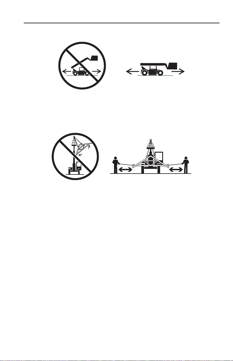
• DO NOT drive with boom raised.
Suspended Load
Section 1 - General Safety Practices
• Tether suspended loads to restrict movement.
• Weight of all rigging (slings, etc.) must be included as part of load.
• Beware of wind. Wind can cause a suspended load to swing and cause dangerous side
loads - even with tag lines.
• DO NOT attempt to use telehandler frame-leveling to compensate for load swing.
• Keep heavy part of load closest to attachment.
• Never drag the load; lift vertically.
When driving with a suspended load:
• Start, travel, turn and stop slowly to prevent load from swinging.
• DO NOT extend boom.
• DO NOT raise the load more than 300 mm (11.8 in) above ground surface or the
boom more than 45°.
• DO NOT exceed walking speed.
1-531200938
Page 16

Section 1 - General Safety Practices
OAL2030
2-Wheel Front Steer 4-Wheel Circle Steer 4-Wheel Crab Steer
Travel Hazard
• Steering characteristics differ between steer modes. Identify the steer mode settings
of the telehandler being operated.
• DO NOT change steer modes while traveling. Steer modes must be changed while
telehandler is stationary.
• Visually verify proper wheel alignment after each steer mode change.
• Ensure that adequate clearance is provided for both rear tail swing and front fork
swing.
• Look out for and avoid other personnel, machinery and vehicles in the area. Use a
spotter if you DO NOT have a clear view.
• Before moving be sure of a clear path and sound horn.
• When driving, retract boom and keep boom/attachment as low as possible while
maintaining visibility of mirrors and maximum visibility of path of travel.
• Always look in the direction of travel.
• Always check boom clearances carefully before driving underneath overhead
obstructions. Position attachment/load to clear obstacles.
• When driving in high speed, use only front wheel steer (if steering modes are
selectable).
• Telehandlers equipped with solid tires should not be used in applications requiring
excessive roading or driving extended distances. In the event an application requires
excessive roading or driving expanded distances, it is recommended to use
telehandlers not equipped with solid tires.
1-6 31200938
Page 17

Section 1 - General Safety Practices
OW0130
Load Falling Hazard
• Never suspend load from forks or other parts of carriage weldment. Use only JLG
approved lift points.
• DO NOT burn or drill holes in fork(s).
• Forks must be centered under load and spaced apart as far as possible.
1-731200938
Page 18

Section 1 - General Safety Practices
OW0170
O
W0190
Lifting Personnel
• When lifting personnel, USE ONLY an approved personnel work platform, with proper
capacity chart displayed in the cab.
• DO NOT drive machine from cab when personnel are in platform.
1-8 31200938
Page 19

Section 1 - General Safety Practices
OW0200
Driving Hazards on Slopes
To maintain sufficient traction and braking capabilities, travel on slopes as follows:
• When unloaded, drive with forks pointed downhill.
• When loaded, drive with the forks pointed uphill.
• For additional travel requirements, refer to the appropriate capacity chart.
• To avoid overspeeding the engine and drivetrain when driving down slopes,
downshift to a lower gear and use the service brake as necessary to maintain a slow
speed. DO NOT shift into neutral and coast downhill.
• Avoid excessively steep slopes or unstable surfaces. To avoid tip over DO NOT drive
across excessively steep slopes under any circumstances.
• Avoid turning on a slope. Never engage “inching” or shift to “Neutral” when going
downhill.
• DO NOT park on a slope.
1-931200938
Page 20

Section 1 - General Safety Practices
OW0210
OW0220
O
W0230
Pinch Points and Crush Hazards
Stay clear of pinch points and rotating parts on the telehandler.
• Stay clear of moving parts while engine is running.
• Keep clear of steering tires and frame or other objects.
• Keep clear from under boom.
1-10 31200938
Page 21

Section 1 - General Safety Practices
OW0240
OW0250
OW0260
OW0960
• Keep clear of boom holes.
• Keep arms and hands clear of attachment tilt cylinder.
• Keep hands and fingers clear of carriage and forks.
• Keep others away while operating.
1-1131200938
Page 22

Section 1 - General Safety Practices
OW0280
OW0290
Fall Hazard
• Enter using the proper hand holds and steps provided. Always maintain 3-point
contact when mounting or dismounting. Never grab control levers or steering wheel
when mounting or dismounting the machine.
• DO NOT get off the machine until the shutdown procedure on page 4-3 has been
performed.
• DO NOT carry riders. Riders could fall off machine causing death or serious injury.
1-12 31200938
Page 23

Section 1 - General Safety Practices
OW0300
OW0950
Chemical Hazards
Exhaust Fumes
• DO NOT operate machine in an enclosed area without proper ventilation.
• DO NOT operate the machine in hazardous environments unless approved for that
purpose by JLG and site owner. Sparks from the electrical system and the engine
exhaust can cause an explosion.
Flammable Fuel
• DO NOT fill the fuel tank or service the fuel system near an open flame, sparks or
smoking materials. Engine fuel is flammable and can cause a fire and/or explosion.
Hydraulic Fluid
• DO NOT attempt to repair or tighten any hydraulic hoses or fittings while the engine is
running or when the hydraulic system is under pressure.
• Stop engine and relieve trapped pressure. Fluid in the hydraulic system is under
enough pressure that it can penetrate the skin.
• DO NOT use your hand to check for leaks. Use a piece of cardboard or paper to search
for leaks. Wear gloves to protect hands from spraying fluid.
1-1331200938
Page 24

Section 1 - General Safety Practices
This Page Intentionally Left Blank
1-14 31200938
Page 25

Section 2 - Pre-Operation and Inspection
OAH1000
PARENT METAL CRACK WELD CRACK
SECTION 2 - PRE-OPERATION AND INSPECTION
2.1 PRE-OPERATION CHECK AND INSPECTION
Note: Complete all required maintenance before operating unit.
WARNING
FAL L HA ZARD. Use extreme caution when checking items beyond your normal reach.
Use an approved ladder.
The pre-operation check and inspection, performed at beginning of each work shift or at
each change of operator, should include the following:
1. Cleanliness - Check all surfaces for leakage (oil, fuel or battery fluid) or foreign
objects. Report any leakage to the proper maintenance personnel.
2. Structure - Inspect the machine structure for dents, damage, weld or parent metal
cracks or other discrepancies.
3. Safety Decals - Ensure all safety decals are legible and in place. Clean or replace as
required. See page 2-3 for details.
4. Operation and Safety Manuals - Operation & Maintenance Manual and AEM Safety
Manual (ANSI only) located in cab manual holder.
5. Walk-Around Inspection - See page 2-6 for details.
6. Fluid Levels - Check fluids, including fuel, hydraulic oil, engine oil and coolant. When
adding fluids, refer to Section 7 - Lubrication and Maintenance and Section
9 - Specifications to determine proper type and intervals. Before removing filler caps
or fill plugs, wipe all dirt and grease away from the ports. If dirt enters these ports, it
can severely reduce component life.
7. Attachments/Accessories - Ensure correct capacity charts are installed on the
telehandler. If provided, reference the Operation & Maintenance Manual of each
attachment or accessory installed for specific inspection, operation and maintenance
instructions.
2-131200938
Page 26

Section 2 - Pre-Operation and Inspection
8. Operational Check - Once the walk-around inspection is complete, perform a warmup and operational check (see page 2-8) of all systems in an area free of overhead
and ground level obstructions. See Section 3 - Controls and Indicators for more
specific operating instructions.
WARNING
If telehandler does not operate properly, immediately bring machine to a stop, lower
boom and attachment to ground and stop the engine. Determine cause and correct
before continued use.
2-2 31200938
Page 27

Section 2 - Pre-Operation and Inspection
OZ4360
1001100957
1001100957
8006038
8006038
1706285
1706098
1706098B
8005670
1001139164A
1001139164
AU2105
AU2105
1001138051
(IF EQUIPPED -
GERMANY)
JLG MANUFACTURING EUROPE BVBA
1001138051
HOMOLOGATION NUMBER:
NUMERO DI OMOLOGAZIONE:
GENEHMIGUNGS NUMMER:
NUMERO IDENTIFICAZIONE:
VEHICLE IDENTIFICATION NUMBER:
FAHRZEUG-IDENTIFIZIERUNGS-NUMMER:
ALLOWED TOTAL WEIGHT:
MASSA TOTALEAMMISSIBILE:
ZUL. GESAMTGEWICHT:
ALLOWED FRONTAXLE WEIGHT:
CARICOAMMISSIBILE SULLASSEANTERIORE:
ZUL.ACHSLAST VORN:
ALLOWED REARAXLE WEIGHT:
CARICOAMMISSIBILE SULLASSE POSTERIORE:
ZUL.ACHSLAST HINTEN:
Kg
Kg
Kg
PERMISSIBLE TOWABLE MASS:
MASSA RIMORCHIABILEAMMISSIBILE:
TECHNISCH ZULAESSIGEANHAENGELAST:
-:UNBRAKED TOWABLE MASS
MASSA RIMORCHIABILE NON FRENATA:
UNGEBREMSTEANHAENGELAST:
-:INDEPENDENTLY-BRAKED TOWABLE MASS
MASSA RIMORCHIABILE CON FRENATURA INDIPENDENTE:
ANHAENGELAST FUER UNABHAENGIGE BREMSUNG:
-:INERTIA-BRAKED TOWABLE MASS
MASSA RIMORCHIABILE CON FRENATURAAD INERZIA:
AUFLAUFGEBREMSTEANHAENGELAST:
-TOWABLE MASS FITTED WITHANASSISTED BRAKING
SYSTEM:
(HYDRAULIC OR PNEUMATIC)
MASSA RIMORCHIABILE CON FRENATURAASSISTITA:
(IDRAULICA O PNEUMATICA)
Kg
Kg
Kg
Kg
TYPE/MODEL:
TIPO/MODELLO:
TYP/MODELL:
TIPO/MODELO:
NÚMERO DE HOMOLOGACIÓN:
NÚMERO DE IDENTIFICACIÓN:
MASA TOTALAUTORIZADA:
CARGAAUTORIZADA SOBRE EL EJE DELANTERO:
CARGAAUTORIZADA SOBRE EL EJE TRASERO:
MASA REMOLCABLEADMISIBLE:
MASA REMOLCABLE NO FRENADA:
MASA REMOLCABLE CON FRENADO INDEPENDIENTE:
MASA REMOLCABLE FRENADA POR INERCIA:
HYDRAULSCH ODER PNEUMATISCH GEBREMSTE
ANHAENGELAST:
MASA REMOLCABLE CON FRENADOASISTID:
(HIDRÁULICO-NEUMÁTICO)
YEAR OF MANUFACTURE:
ANNO DI FABRICAZIONE:
BAUJAHR:
AÑO DE FABRICACIÓN:
8008657
8008657B
8005617
20 - 2603207
(GERMANY)
25 - 1001153442
(FRANCE)
20
3700016
8008657
8008657B
8005671
8005671
8005675
8005616
3700016
3700016
8006612
1001121555
(RUSSIA)
MP13
1001121555 A
1001168718A
1001168718
1001139647
ModelYear:
100100YYYA
Model:
Year of Manufacture:
Product Identification Number
Serial Number
Nominal engine power, kW:
Unladen mass:
Maximum capacity:
Maximum capacity at max. Height:
kg
kg
kg
JLG Manufacturing Europe BVBA
Industrieterrein Oude Bunders 1034
Breitwaterstraat 12
3630 Maasmechelen - Belgium
1001139647A
1001173703
(RUSSIA)
VIEW OF ENGINE
COMPART MENT
2.2 SAFETY DECALS
Ensure all DANGER, WAR NI NG, CAUTION and instructional decals and proper capacity
charts are legible and in place. Clean and replace as required.
2-331200938
Page 28

Section 2 - Pre-Operation and Inspection
OZ4370
20 - 2603207
(GERMANY)
25 - 1001153442
(FRANCE)
20
8006612
8006612
8005870
8005870
1001104319
1001158844
1001158844A
8005675
3700016
8008657
8008657B
8005617
8005616
37000163700016
8005671
8005671
8006612
8008657
8008657B
A
1001168718A
1001168718
20 - 2603207
(GERMANY)
25 - 1001153442
(FRANCE)
20
D
1001139654 A
S
15 mg/kg
1001139654
(IF EQUIPPED FOR ULS)
1001102782
L
WA
06
dB
1
1705980
A - 1706753
B - 1706754
C - 1706755
D - 1706756
ABCD
2-4 31200938
Page 29

OZ4381
1706209
ON OFF
P P
A
A
B
B
B
A
B
B
B
A
A
A
A
A
C
C
A
A
A
EVERY
C
5
00
5
0
A
5
0
B
3614RS - 1001161264
4017RS - 1001165433
XXX kg MAX
-
XXX mm
XXX mm
XXXX
EN 1459:1998-ANNEX B
8m
9m
10m
11m
12m
13m
14m
o
10
o
20
o
30
o
40
o
50
o
60
o
75
o
0
0m
-1m
1m
2m
3m
4m
5m
6m
7m
0m
1m
2m
3m4m5m
9m 8m
7m
6m
XXX mm
350kg
500kg
750kg
100
0kg
1500kg
2000kg
2500kg
3700kg
A
B
C
D
10
D
50
150
LB
F
T
(m
N
)
50
1001161263
XXXX
XXX
XX
XXXXXX
1001094708B
1001094708
1001158300
3m
1001101895
1001101895
8005670
8005670
Korrekter Bodenabstand von 290-300mm
(ab Unterkante Schaufel)
wird durch rote Linie angezeigt
1001119218
(GERMANY)
1001172172
(LIFT PATTERN)
1001158303
(LOADER PATTERN)
1001158309
1001092878
1001120989A
1001120989
(IF EQUIPPED
WITH CLEARSKY)
VIEW A-A
AA
CAPACITY
CHARTS
B
EN 15830
CHARTS
B
VIEW B-B
Section 2 - Pre-Operation and Inspection
2-531200938
Page 30

Section 2 - Pre-Operation and Inspection
OZ3892
16
2
3
1
4
5
6
8
9
11
10
12
13
14
15
17
18
7
19
19
20
20
2.3 WALK-AROUND INSPECTION
-
Begin your walk-around inspection at item 1, as noted below. Continue to your right
(counterclockwise when viewed from top) checking each item in sequence.
INSPECTION NOTE: On all components, make sure there are no loose or missing parts, that
they are securely fastened and no visible leaks or excessive wear exists in addition to any
other criteria mentioned. Inspect all structural members including attachment for cracks,
excessive corrosion and other damage.
1. Boom Sections and Lift, Tilt, Extend/Retract, Compensating (Slave) Cylinders
• Check front, top, side and rear wear pads for presence of grease.
• Pivot pins secure; hydraulic hoses undamaged, not leaking.
2-6 31200938
Page 31

Section 2 - Pre-Operation and Inspection
2. Front Axle - Steer cylinders undamaged, not leaking; pivot pins secure (if equipped);
hydraulic hoses undamaged, not leaking.
3. Left Outrigger
4. Wheel/Tire Assembly
Inspect for worn tread, cuts, tears or other discrepancies.
5. Mirror
6. Cab and Electrical
• General appearance; no visible damage.
• Frame level indicator(s) and window glass undamaged and clean.
• Gauges, switches, joystick, foot controls and horn operational.
• Check seat belt for damage, replace belt if frayed or cut webbing, damaged
buckles or loose mounting hardware.
7. Wheel Chock
8. Wheel/Tire Assembly
Inspect for worn tread, cuts, tears or other discrepancies.
9. LSI Sensor
10. Main Control Valve
11. Rear Axle
hoses undamaged, not leaking.
12. Wheel/Tire Assembly
Inspect for worn tread, cuts, tears or other discrepancies.
13. Engine Compartment
• Drive belts, check condition and replace as required.
• Engine mounts - See inspection note.
• Battery cables tight, no visible damage or corrosion.
• Engine cover properly secured.
14. Mirrors
- Pins secure; hydraulic hoses and cylinder undamaged, not leaking.
- Properly inflated and secured; no loose or missing lug nuts.
- Clean and undamaged.
-
(if equipped) - See inspection note.
- Properly inflated and secured; no loose or missing lug nuts.
- See inspection note.
- See inspection note.
- Steer cylinders undamaged, not leaking; pivot pins secure; hydraulic
- Properly inflated and secured; no loose or missing lug nuts.
-
- Clean and undamaged.
15. Wheel/Tire Assembly
Inspect for worn tread, cuts, tears or other discrepancies.
16. Frame Level Cylinder
17. Right Outrigger
18. Attachment
19. Front Lights
20. Rear Lights
horizontal position. For off-road use, orientate in the horizontal or down position.
See “Road Operation (CE)” on page 4-10.
- Properly installed, see “Attachment Installation” on page 5-10.
(if equipped) - Clean and undamaged.
(if equipped) - Clean and undamaged. For road use, orientate in the
- Properly inflated and secured; no loose or missing lug nuts.
- Pins secure; hydraulic hoses undamaged, not leaking.
- Pins secure; hydraulic hoses and cylinder undamaged, not leaking.
2-731200938
Page 32

Section 2 - Pre-Operation and Inspection
2.4 WARM-UP AND OPERATIONAL CHECKS
Warm-Up Check
During warm-up period, check:
1. Heater, air conditioning and wipers (if equipped).
2. Check all lighting systems (if equipped) for proper operation.
3. Adjust mirrors for maximum visibility.
WARNING
CUT/CRUSH/BURN HAZARD. Keep engine cover closed while engine is running.
Operational Check
When engine warms, perform an operational check:
1. Service brake and parking brake operation.
2. Forward and reverse travel.
3. Each gear.
4. Steering in both directions with engine at low idle (steering lock to lock will not be
reached). Check in each steering mode
5. Horn and back-up alarm. Must be audible from inside operators cab with engine
running.
6. All joystick functions - operate smoothly and correctly.
7. Perform any additional checks described in Section 8.
2-8 31200938
Page 33

Section 2 - Pre-Operation and Inspection
2.5 OPERATOR CAB
The telehandler is equipped with an open or enclosed ROPS/FOPS cab.
WARNING
Never operate telehandler unless the overhead guard, cab structure and right side
glass or screen are in good condition. Any modification to this machine must be
approved by JLG to assure compliance with ROPS/FOPS certification for this cab/
machine configuration. If the overhead guard or cab structure is damaged, the CAB
CANNOT BE REPAIRED. It must be REPLACED.
2-931200938
Page 34

Section 2 - Pre-Operation and Inspection
OAM3880
1
2
3
4
2.6 WINDOWS
Keep all windows clean and unobstructed.
Cab Door Window
• Cab door (1) must be closed during operation.
• During operation the cab door window (2) must either be latched open or closed.
• Open the cab door window using lever (3) and secure it in the latch (4).
• Press the release inside the cab to unlatch the window.
2-10 31200938
Page 35

Section 2 - Pre-Operation and Inspection
5
6
OAM2110
Rear Window
•Lift lever (5) and push to open the rear window (6).
• Lift lever and pull to close.
2-1131200938
Page 36

Section 2 - Pre-Operation and Inspection
This Page Intentionally Left Blank
2-12 31200938
Page 37

Section 3 - Controls and Indicators
SECTION 3 - CONTROLS AND INDICATORS
3.1 GENERAL
This section provides the necessary information needed to understand control functions.
3-131200938
Page 38

Section 3 - Controls and Indicators
OZ4010
9
3
1
4
2
6
7
8
5
11
10
12
13
14
5
3.2 CONTROLS
1. Park Brake: See page 3-7.
2. Accelerator Pedal
3. Ignition Switch
4. Service Brake Pedal
5. Console Switches
6. Climate Controls
7. Transmission Control Lever
8. Steering Wheel
the corresponding direction. Three steering modes are available. See “Steer Modes”
on page 3-24.
9. Steering Column Adjuster
10. Instrument Cluster
3-2 31200938
: Pressing down the pedal increases engine and hydraulic speed.
: Key activated. See page 3-6.
: The further the pedal is depressed, the slower the travel speed.
: See page 3-20.
: See page 3-21.
: See page 3-8.
: Turning the steering wheel to the left or right steers the machine in
: See page 3-12.
: See page 3-4.
Page 39

11. Accessory Control Lever: See page 3-22.
12. Joystick
: See page 3-14.
Section 3 - Controls and Indicators
13. LSI Indicator
14. Frame Level Indicator
of the telehandler.
: See page 3-10.
: Enables operator to determine the left to right level condition
3-331200938
Page 40

Section 3 - Controls and Indicators
OZ4081
1
2
3
4
5
6
7
8
11
1
1 KPH
1127 RPM
127°C
10
9
12
0000
DISPLAY SHOWN WITH ANTI THEFT
ACTIVE AT SYSTEM START
DISPLAY SCREEN
Instrument Cluster
NOTICE
EQUIPMENT DAMAGE. When a red indicator illuminates (except park brake),
immediately bring machine to a stop, lower boom and attachment to ground and stop
the engine. Determine cause and correct before continued use.
1. Low Fuel Indicator: Illuminates when fuel level is low.
2. Fuel Gauge:
3. Engine Warning Light
bring machine to a stop, retract and lower boom and stop the engine. Determine
cause and correct before continued use.
4. Engine Preheat Indicator
out when start temperature is reached.
5. Steer Mode Indicators
6. System Distress Indicator
system is present. Flashes when an issue with the machine charge system is present.
7. Park Brake Indicator
3-4 31200938
Indicates amount of fuel in fuel tank.
: Illuminates when the engine is in a critical state. Immediately
: Illuminates with ignition key in position 1. Indicator goes
: Illuminates active steering mode.
: Illuminates when an issue with the fuel level or machine
: Illuminates when park brake is applied.
Page 41

Section 3 - Controls and Indicators
8. Check Engine Indicator: Illuminates when maintenance is required. See Service
Manual for details.
Note: All indicators perform a bulb check at system start up.
Display Screen
9. Speed, Boom Angle and Operating Hours
a. Speed - Telehandler travel speed displayed in kilometers per hour (km/h) or miles
per hour (m/h).
b. Boom Angle - Displays boom angle in degrees.
c. Operating Hours - Displays total hours of telehandler operation. Displays when
ignition is in ON position and engine is not started.
10. Engine Coolant Temperature and Fault Codes
a. Engine Coolant Temperature - Displays engine coolant temperature.
b. Fault Codes - Replaces the engine coolant temperature. Displays fault codes of
engine and machine systems. See Service Manual for details.
11. Driving Direction and Gear, Engine Speed and Operating Hours
a. Driving Direction and Gear - Displays current driving condition.
Direction - Forward (F), Neutral (N) or Reverse (R).
Gear - First (1), Second (2) or Third (3).
b. Engine Speed - Displays engine speed in revolutions per minute (rpm).
c. Battery Voltage - Displays voltage supplied by battery. Displays when vehicle is
not in motion.
12. Anti Theft Code Entry
the engine. See “An ti Th eft” on page 3-23.
: If active, the four digit code must be entered prior to starting
:
:
:
3-531200938
Page 42

Section 3 - Controls and Indicators
OZ2300
0
I
II
III
P
Ignition
• Position 0 - Engine off.
• Position I - Voltage available for all electrical functions.
• Position II - Wait to start engine until preheat indicator on instrument panel goes out.
• Position III - Engine start. In the event the engine does not start, rotate key to position
0 then back to position III to re-engage the starter.
• Position P - Not active, reserved for future use.
Note: Key is removable in the 0 and P positions.
3-6 31200938
Page 43

Section 3 - Controls and Indicators
OZ4090
1
2
3
1
4017RS3614RS
Park Brake
The park brake lever (1) controls the application and release of the park brake.
• Pull lever back to apply park brake.
• 3614RS - Squeeze release (2) and push lever forward to release park brake.
4017RS - Lift detent ring (3) and push lever forward to release park brake.
WARNING
MACHINE ROLL-AWAY HAZARD. Always move park brake lever to "ON" position,
lower boom to ground and stop engine before leaving cab.
WARNING
CRUSH HAZARD. Applying park brake while traveling will cause unit to stop abruptly
and could cause load loss. To stop the machine in an emergency, apply the park brake.
Parking Procedure
1. Using service brake, stop telehandler in an appropriate parking area.
2. Follow “Shut-Down Procedure” on page 4-3.
3-731200938
Page 44

Section 3 - Controls and Indicators
OZ4131
F
N
R
1
Transmission Control Lever (if equipped)
Direction of Travel Selection
Transmission control lever (1) engages forward or reverse travel.
• Push lever forward for forward travel; pull lever rearward for reverse travel. Move lever
to centered position for neutral.
• Forward or reverse travel can be selected while in any gear.
• When traveling in reverse, the back-up alarm will automatically sound.
• Drive in reverse and turn only at slow rates of speed.
• If clutch lock is activated do not increase engine speed with the transmission in
forward or reverse and the service brake depressed in an attempt to get quicker
hydraulic performances. This could cause unexpected machine movement.
WARNING
TIP OVER/CRUSH HAZARD. Bring telehandler to a complete stop before shifting
transmission control lever. A sudden change in direction of travel could reduce
stability and/or cause load to shift or fall.
3-8 31200938
Page 45

Section 3 - Controls and Indicators
OZ4142
2
2
nd
3
rd
1
st
Gear Selection
Gear selection is located on the twist grip handle (2) of transmission control lever.
• Twist hand grip to select gear.
• The Transmission is equipped with three forward and three reverse gears.
• Select the appropriate gear for the task being performed. Use a lower gear when
transporting a load. Use a higher gear only when driving unloaded for longer
distances.
• Slow down prior to downshifting. Do not downshift more than one gear at a time.
Downshifting is not permitted if current gear is flashing on display. Intended
downshifting speeds are 9 kph (5.5 mph) for third to second gear and 4 kph (2.5 mph)
for second to first gear.
3-931200938
Page 46

Section 3 - Controls and Indicators
OZ4100
1
2
3
4
5
6
Load Stability Indicator - LSI
WARNING
TIP OVER HAZARD. The LSI considers only longitudinal stability limitations, observe
all operating parameters. Failure to follow operating parameters of the telehandler
could damage the equipment and/or cause tip over.
The LSI (1) provides visual and audible indication of forward stability limitations when
machine is static on firm, level surface.
• Green LED (2) will illuminate when LSI power is on.
• When approaching forward stability limitations LEDs progressively illuminate, green
(3), then orange (4) and finally red (5).
• If the red LED illuminates the warning buzzer also sounds.
• As the telehandler reaches forward stability limitations and the red LED (5) illuminates,
the automatic function cut-out is activated. All boom, frame level and outrigger
functions are disabled except for boom retract (CE & AUS) and boom lift (CE). Retract
boom to re-enable functions.
• In some instances the LSI system may slow down or stop boom functions if operated
close to forward stability limitations. When LEDs begin to flash, certain functions can
not be operated. Retract boom and/or return the joystick to neutral position for a
short period to allow system to reset and LEDs to stop flashing before proceeding
with operation.
3-10 31200938
Page 47

Section 3 - Controls and Indicators
• Travel in accordance with the requirements set forth in Section 1 - General Safety
Practices.
•Test LSI (6) at the beginning of each work shift. See Section 8 - Additional Checks.
• When placing a load, ensure axles are not fully steered in either direction.
WARNING
TIP OVER HAZARD. If the green, orange and red LEDs flash and warning buzzer
sounds, retract and lower boom immediately. Determine cause and correct before
continued use.
3-1131200938
Page 48

Section 3 - Controls and Indicators
OZ4120
1
Steering Column Adjuster
• Follow “Shut-Down Procedure” on page 4-3.
•Turn lever (1) counterclockwise to unlock.
• Place steering column in desired position.
• Turn lever clockwise to lock.
WARNING
TIP OVER/CRUSH HAZARD. Bring telehandler to a complete stop and shutdown
engine before adjusting steering column. A sudden change in direction of travel could
reduce stability and/or cause load to shift or fall.
3-12 31200938
Page 49

Section 3 - Controls and Indicators
This Page Intentionally Left Blank
3-1331200938
Page 50

Section 3 - Controls and Indicators
OZ3940
5
F
N
R
7
2
3
8
5
4
9
6
1
Joystick
Verify the joystick decal located inside the cab matches the machine controls.
Lift Joystick Pattern
The joystick (1) controls the boom, attachment, auxiliary hydraulics, outrigger and
transmission functions.
Boom Functions
• Move the joystick back to lift boom; move joystick forward to lower boom; move
joystick right to extend boom; move joystick left to retract boom.
• The speed of boom functions depends upon the amount of joystick travel in
corresponding direction. Increasing engine speed will also increase function speed.
• For two simultaneous boom functions, move the joystick between quadrants. For
example; moving the joystick forward and to the left will lower and retract boom
simultaneously.
3-14 31200938
Page 51

Section 3 - Controls and Indicators
WARNING
TIP OVER/CRUSH HAZARD. Rapid, jerky operation of controls will cause rapid, jerky
movement of the load. Such movements could cause the load to shift or fall or could
cause the machine to tip over.
Attachment Functions
Attachment tilt is controlled by the roller switch (2).
• Push the roller switch up to tilt attachment down; push the roller switch down to tilt
attachment up.
Auxiliary Hydraulic Functions (if equipped)
Auxiliary Hydraulics roller switch (3) controls function of attachments that require
hydraulic supply for operation. See Section 5 - Attachments for approved attachments
and control instructions.
Continuous Auxiliary Hydraulic Functions (if equipped)
• Depress and release joystick button (4) for continuous operation of hydraulic powered
attachments.
• Set continuous auxiliary hydraulic level (-100% to 100%) using the auxiliary hydraulic
roller switch (3). Push the roller switch up to increase or down to decrease hydraulic
flow.
• Depress and release joystick button (4) again to stop continuous operation.
Outrigger Functions
Joystick button (5) controls both outriggers.
• Press and hold the button; move the joystick forward to lower both outriggers; move
the joystick back to raise both outriggers.
• Press and hold the button; move the joystick left then forward to lower the left
outrigger; move the joystick left then back to raise the left outrigger.
• Press and hold the button; move the joystick right then forward to lower the right
outrigger; move the joystick right then back to raise the right outrigger.
• Outriggers operable with boom at any extension and below 20 degrees or with boom
fully retracted and below 55 degrees.
WARNING
TIP OVER HAZARD. Outriggers increase stability and load capacity only if they are
used properly. Using outriggers on soft surfaces could cause telehandler to tip over.
Always ensure surface can support telehandler and load.
3-1531200938
Page 52

Section 3 - Controls and Indicators
Transmission Control (if equipped)
Transmission roller switch (6) engages forward or reverse travel.
• Press switch up for forward travel; Press switch down for reverse travel. Move switch to
centered position for neutral.
• Forward or reverse travel can be selected while in any gear.
• When traveling in reverse, the back-up alarm will automatically sound.
• Travel at slow rates of speed when making turns and driving in reverse.
WARNING
TIP OVER/CRUSH HAZARD. Bring telehandler to a complete stop before shifting
transmission. A sudden change in direction of travel could reduce stability and/or
cause load to shift or fall.
Gear selection is controlled by buttons (7 & 8).
• Depress upshift button (7) to select a higher gear; Depress downshift button (8) to
select a lower gear.
• The Transmission is equipped with three forward and three reverse gears.
• Select the appropriate gear for the task being performed. Use a lower gear when
transporting a load. Use a higher gear only when driving unloaded for longer
distances.
• Slow down prior to downshifting. Do not downshift more than one gear at a time.
Downshifting is not permitted if current gear is flashing on display. Intended
downshifting speeds are 9 kph (5.5 mph) for third to second gear and 4 kph (2.5 mph)
for second to first gear.
Clutch Lock is controlled by button (9).
• Squeeze and hold trigger to deactivate system and have transmission disengage
while depressing service brake. Release trigger to activate system and keep
transmission engaged while depressing service brake.
3-16 31200938
Page 53

Loader Joystick Pattern
OZ4110
5
F
N
R
7
2
3
8
5
4
9
6
1
Section 3 - Controls and Indicators
The joystick (1) controls the boom, attachment, auxiliary hydraulics, outrigger and
transmission functions.
Boom Functions
• Move the joystick back to lift boom; move joystick forward to lower boom.
• Extend/retract is controlled by the roller switch (2). Push roller switch up to extend
boom; push roller switch down to retract boom.
• The speed of boom functions depends upon the amount of joystick travel in
corresponding direction. Increasing engine speed will also increase function speed.
• For two simultaneous boom functions, move the joystick between quadrants. For
example; moving the joystick forward and to the left will lower boom and tilt
attachment up simultaneously.
3-1731200938
Page 54

Section 3 - Controls and Indicators
WARNING
TIP OVER/CRUSH HAZARD. Rapid, jerky operation of controls will cause rapid, jerky
movement of the load. Such movements could cause the load to shift or fall or could
cause the machine to tip over.
Attachment Functions
Attachment tilt is controlled by the joystick.
• Move joystick right to tilt down; move joystick left to tilt up.
Auxiliary Hydraulic Functions (if equipped)
Auxiliary Hydraulics roller switch (3) controls function of attachments that require
hydraulic supply for operation. See Section 5 - Attachments for approved attachments
and control instructions.
Continuous Auxiliary Hydraulic Functions (if equipped)
• Depress and release joystick button (4) for continuous operation of hydraulic powered
attachments.
• Set continuous auxiliary hydraulic level (-100% to 100%) using the auxiliary hydraulic
roller switch (3). Push the roller switch up to increase or down to decrease hydraulic
flow.
• Depress and release joystick button (4) again to stop continuous operation.
Outrigger Functions
Joystick button (5) controls both outriggers.
• Press and hold the button; move the joystick forward to lower both outriggers; move
the joystick back to raise both outriggers.
• Press and hold the button; move the joystick left then forward to lower the left
outrigger; move the joystick left then back to raise the left outrigger.
• Press and hold the button; move the joystick right then forward to lower the right
outrigger; move the joystick right then back to raise the right outrigger.
• Outriggers operable with boom at any extension and below 20 degrees or with boom
fully retracted and below 55 degrees.
WARNING
TIP OVER HAZARD. Outriggers increase stability and load capacity only if they are
used properly. Using outriggers on soft surfaces could cause telehandler to tip over.
Always ensure surface can support telehandler and load.
3-18 31200938
Page 55

Section 3 - Controls and Indicators
Transmission Control (if equipped)
Transmission roller switch (6) engages forward or reverse travel.
• Press switch up for forward travel; Press switch down for reverse travel. Move switch to
centered position for neutral.
• Forward or reverse travel can be selected while in any gear.
• When traveling in reverse, the back-up alarm will automatically sound.
• Travel at slow rates of speed when making turns and driving in reverse.
WARNING
TIP OVER/CRUSH HAZARD. Bring telehandler to a complete stop before shifting
transmission. A sudden change in direction of travel could reduce stability and/or
cause load to shift or fall.
Gear selection is controlled by buttons (7 & 8).
• Depress upshift button (7) to select a higher gear; Depress downshift button (8) to
select a lower gear.
• The Transmission is equipped with three forward and three reverse gears.
• Select the appropriate gear for the task being performed. Use a lower gear when
transporting a load. Use a higher gear only when driving unloaded for longer
distances.
• Slow down prior to downshifting. Do not downshift more than one gear at a time.
Downshifting is not permitted if current gear is flashing on display. Intended
downshifting speeds are 9 kph (5.5 mph) for third to second gear and 4 kph (2.5 mph)
for second to first gear.
Clutch Lock is controlled by button (9).
• Squeeze and hold trigger to deactivate system and have transmission disengage
while depressing service brake. Release trigger to activate system and keep
transmission engaged while depressing service brake.
3-1931200938
Page 56

Section 3 - Controls and Indicators
OZ4150
1
2
3
4
5
6
7
8 9
10
11
12
13
15
16
14
Console Switches
1. Joystick Function Switch: On/Off switch. All joystick functions are enabled when on.
2. LSI Override Switch
and hold up to 30 seconds while operating joystick to momentarily disable the
automatic function cut-out.
3. Rear Wiper Switch
4. Roof Wiper Switch
: Momentarily disables the automatic function cut-out. Depress
: On/Off switch.
(if equipped): On/Off switch.
5. Hazards Lights Switch
6. Driving Lights Switch
7. Fog Lights Switch
8. Beacon Light Switch
cab roof. Power supplied by 12V receptacle at rear left of cab roof.
9. Front and Rear Cab Work Lights Switch
10. Steer Select Switch
wheel steer. See page 3-24.
11. High Beam and Turn Signal Indicators
are active.
12. Power Outlet
: 12V receptacle.
3-20 31200938
: On/Off switch.
(if equipped): On/Off switch.
(if equipped): On/Off switch.
(if equipped): On/Off switch. Place magnetic base of beacon on
: Three positions: 4-wheel circle steer, 4-wheel crab steer and 2-
(if equipped): On/Off switch.
: Illuminates when high beams or turn signals
Page 57

Section 3 - Controls and Indicators
13. Frame Level Switch: Controls the left to right frame level. Depress right side of switch
to rotate frame right; depress left side of switch to rotate frame left. Frame level
operable with boom below 20 degrees or with boom fully retracted and between 20
and 55 degrees.
Climate Controls
14. Air Conditioning Switch
15. Fan Speed Switch
: On/Off switch.
: Adjustable rotary switch.
16. Temperature Control
: Adjustable lever.
3-2131200938
Page 58

Section 3 - Controls and Indicators
OZ4340
1
2
3
4
OZ4350
1
O
I
II
5
6
Accessory Control Lever
Turn Signals and Low/High Beam Headlights
• Push accessory control lever (1) forward (2) to activate left turn signal.
• Pull lever backward (3) to activate right turn signal.
• The lever must be manually returned to the center position to deactivate either turn
signal. The lever will not cancel automatically after a turn.
• Pull lever up (4) to switch between low and high beam headlights.
Front Windshield Wiper
• Rotate hand grip (5) to activate front windshield wiper.
O - Off, I - Continuous or II - Fast
• Push hand grip (5) towards column to activate windshield wiper fluid.
Horn
• Depress button (6) at end of lever to sound horn.
3-22 31200938
Page 59

Section 3 - Controls and Indicators
OZ4460
1
0000
O 4470Z
2
3
3.3 ANTI THEFT
Machines with the anti theft feature active require entering a numeric code before
operation to prevent unauthorized use. Code entry is accomplished using the display and
joystick.
1. Turn ignition switch to position I. If anti theft is active, the display (1) will prompt the
operator for a numeric code.
2. Use the joystick roller switch (2) to select the first digit. Push roller switch up to
increase the number; push roller switch down to decrease the number.
3. Depress and release joystick button (3) to enter the current number.
4. Continue until the code is complete.
5. If an incorrect code is entered, the buzzer will sound briefly and the display will
prompt the operator again for the numeric code.
6. If the correct code is entered, normal start up can continue.
Note: If the anti theft feature is active and the current access code is not known, it may be
viewed in Diagnostics > Datalog Menu or changed in Operator Tools Menu (level 2 password
required for both). See Service Manual for information.
3-2331200938
Page 60

Section 3 - Controls and Indicators
OAL2030
2-Wheel Front Steer 4-Wheel Circle Steer 4-Wheel Crab Steer
OZ4160
3
2
1
OAM2400
4 5
3.4 STEER MODES
Three steer modes are available for operator use.
Note: 2-Wheel Front Steer mode is required for travel on public roads.
Manual Steering Alignment Mode Change
Note: Steer mode will change immediately after selection.
1. Bring machine to a stop using service brake. If front steer mode (2) is active and rear
wheels are aligned, go directly to step 4.
2. With circle steer (1) or crab steer (3) mode active, turn the steering wheel until the
left rear wheel (4) is aligned with the side of the machine.
3. Select front steer mode (2).
4. Turn the steering wheel until the left front wheel (5) is aligned with the side of the
machine.
5. Wheels are now aligned. Select desired steer mode.
3-24 31200938
Page 61

Section 3 - Controls and Indicators
OZ4181
3
1
3
2
(IF EQUIPPED)
(IF EQUIPPED)
3.5 OPERATOR SEAT
Operator Presence
The operator seat (1) is equipped with an operator presence system. Engine start and
hydraulic functions are prohibited if operator is not present. If the system detects a loss of
pressure during operation, after a two second delay one of the following will occur:
1. With the park brake (2) engaged and transmission in neutral (3):
• Hydraulic controls are disabled. (Continuous Auxiliary function permitted)
• Upon returning to seated position, hydraulic controls are enabled.
2. With the park brake (2) disengaged and transmission in neutral (3):
• Hydraulic controls are disabled and horn sounds continuously. (Continuous
Auxiliary function permitted)
• Upon returning to seated position, hydraulic controls are enabled and horn will
cease.
3. With the park brake (2) disengaged and transmission in forward or reverse (3):
• Hydraulic controls are disabled, horn sounds continuously and transmission shifts
to neutral.
• Upon returning to seated position, hydraulic controls are enabled and horn will
cease. Return transmission to neutral to allow system to reset prior to reengaging
forward or reverse travel.
3-2531200938
Page 62

Section 3 - Controls and Indicators
OZ4170
1
2
3
4
5
5
Adjustments
Prior to starting the engine adjust seat for position and comfort.
1. Fore/Aft: Use handle to move seat fore and aft.
2. Suspension
setting.
3. Weight
4. Backrest
5. Seat Belt
3-26 31200938
: Use the handle to adjust the suspension to the appropriate weight
: Displays current weight setting.
: Use lever to adjust backrest angle.
: Always fasten seat belt during operation.
Page 63

Section 3 - Controls and Indicators
OH20912
Seat Belt
Fasten seat belt as follows:
1. Grasp both free ends of the belt making certain that belt webbing is not twisted or
entangled.
2. With back straight in the seat, couple the retractable end (male end) of the belt into
the receptacle (buckle) end of the belt.
3. With belt buckle positioned as low on the body as possible, pull the retractable end
of the belt away from the buckle until it is tight across the lap.
4. To release belt latch, depress red button on the buckle and pull free end from buckle.
3-2731200938
Page 64

Section 3 - Controls and Indicators
OAM3750
1
A
B
3.6 BOOM INDICATORS
Boom Extension
• The boom extension indicators (1) are located on the left side of the boom. Use these
indicators to determine boom extension when using the capacity chart (see “Use of
the Capacity Chart” on page 5-5).
3-28 31200938
Page 65

Section 4 - Operation
SECTION 4 - OPERATION
4.1 ENGINE
Note: Refer to Engine Operation & Maintenance Manual for additional information.
Starting the Engine
This machine can be operated under normal conditions in temperatures of -20°C to 48°C
(0°F to 118°F). Consult JLG for operation outside this range or under abnormal conditions.
1. Make sure all controls are in “Neutral” and all electrical components (lights, heater,
etc.) are turned off. Apply park brake.
2. Turn ignition switch to position II and wait for engine preheat indicator on
instrument panel to go out. If active, enter anti theft code.
3. Turn ignition switch to position III to engage starting motor. Release key immediately
when engine starts. If engine fails to start within 20 seconds, release key and allow
starting motor to cool for a few minutes before trying again.
4. After engine starts, observe indicators. If indicators remain on for more than five
seconds, stop engine and determine cause before restarting engine.
5. Warm up engine at approximately 1/2 throttle.
Note: Engine will not start unless transmission is in neutral and park brake is applied.
WARNING
UNEXPECTED MOVEMENT HAZARD. Always ensure that transmission is in neutral
and the service brake is applied before releasing park brake. Releasing park brake in
either forward or reverse could cause the machine to move abruptly.
WARNING
ENGINE EXPLOSION. Do not spray ether into air intake for cold weather starting.
4-131200938
Page 66

Section 4 - Operation
OW0530
Battery Boosted Starting
If battery-boost starting (jump-start) is necessary, proceed as follows:
• Never allow vehicles to touch.
• Ensure boosting vehicle engine is running.
• Connect the positive (+) jumper cable to positive (+) post of discharged battery.
• Connect the opposite end of positive (+) jumper cable to positive (+) post of booster
battery.
• Connect the negative (-) jumper cable to negative (-) post on booster battery.
• Connect opposite end of negative (-) jumper cable to ground point on machine away
from discharged battery.
• Follow standard starting procedures.
• Remove cables in reverse order after machine has started.
WARNING
BATTERY EXPLOSION HAZARD. Never jump start or charge a frozen battery as it
could explode. Keep sparks, flames and lighted smoking materials away from the
battery. Lead acid batteries generate explosive gases when charging. Wear safety
glasses.
4-2 31200938
Page 67

Section 4 - Operation
Normal Engine Operation
• Observe instrument panel and display frequently to be sure all systems are
functioning properly.
• Be alert for unusual noises or vibration. When an unusual condition is noticed, park
machine in safe position and perform shut-down procedure. Report condition to your
supervisor or maintenance personnel.
• Avoid prolonged idling. If the engine is not being used, turn it off.
Shut-Down Procedure
When parking the telehandler, park in a safe location on flat level ground and away from
other equipment and/or traffic lanes.
1. Apply the park brake.
2. Shift the transmission to “Neutral.”
3. Lower forks or attachment to the ground.
4. Operate engine at low idle for 3 to 5 minutes. DO NOT over rev engine.
5. Shut off engine and remove ignition key.
6. Exit telehandler properly.
7. Turn off electrical master switch (if equipped).
8. Block wheels (if necessary).
4-331200938
Page 68

Section 4 - Operation
4.2 OPERATING WITH A NON-SUSPENDED LOAD
Lift Load Safely
• You must know the weight and load center of every load you lift. If you are not sure of
the weight and load center, check with your supervisor or with the supplier of the
material.
WARNING
TIP OVER HAZARD. Exceeding lift capacity of the telehandler could damage the
equipment and/or cause tip over.
• Know the rated load capacities (refer to Section 5) of the telehandler to determine the
operating range in which you can safely lift, transport and place a load.
Picking Up a Load
• Note the conditions of the terrain. Adjust travel speed and reduce amount of load if
conditions warrant.
• Avoid lifting double-tiered loads.
• Make sure load is clear of any adjacent obstacles.
• Adjust spacing of forks so they engage the pallet or load at maximum width. See
“Adjusting/Moving Forks” on page 5-17.
• Approach load slowly and squarely with fork tips straight and level. NEVER attempt to
lift a load with just one fork.
• NEVER operate telehandler without a proper and legible capacity chart in the
operator cab for the telehandler/attachment combination you are using.
4-4 31200938
Page 69

Section 4 - Operation
OW0540
Transporting a Load
• After engaging the load and resting it against the backrest, tilt the load back to
position it for travel. Travel in accordance with the requirements set forth in Section
1 - General Safety Practices and Section 5 - Attachments.
Leveling Procedure
1. Position machine in best location to lift or place load.
2. Apply parking brake and shift transmission to NEUTRAL.
3. Observe level indicator(s) to determine whether machine must be leveled prior to
lifting load. If equipped, level machine with frame level switch (see page 3-20) or
outrigger controls (see page 3-15 or 3-18).
4. Move boom/attachment to 1,2 m (4 ft) off ground.
(AUS - Move boom so forks are no more than 300 mm (11.8 in) above ground
surface.)
Important things to remember:
• Never raise the boom/attachment more than 1,2 m (4 ft) above ground unless
telehandler is level.
(AUS - Never raise the forks more than 300 mm (11.8 in) above ground surface unless
telehandler is level.)
• The combination of frame leveling and load could cause the telehandler to tip over.
4-531200938
Page 70

Section 4 - Operation
Placing a Load
Before placing any load be sure that:
• The landing point can safely support the weight of the load.
• The landing point is level; front to back and side to side.
• Use the capacity chart to determine safe boom extension range. See “Use of the
Capacity Chart” on page 5-5.
• Align forks at the level load is to be placed, then position boom slowly until load is just
above area where it is to be placed.
• Lower the boom until the load rests in position and the forks are free to retract.
Disengaging a Load
Once the load has been placed safely at the landing point, proceed as follows:
1. With the forks free from the weight of the load, the boom can be retracted
and/or the telehandler can be backed away from under the load if surface will not
change level condition of telehandler.
2. Lower the carriage.
3. The telehandler can now be driven from the landing location to continue work.
4-6 31200938
Page 71

Section 4 - Operation
4.3 OPERATING WITH A SUSPENDED LOAD
Lift Load Safely
• You must know the weight and load center of every load you lift. If you are not sure of
the weight and load center, check with your supervisor or with the supplier of the
material.
WARNING
TIP OVER HAZARD. Exceeding lift capacity of the telehandler could damage the
equipment and/or cause tip over.
• Know the rated load capacities (refer to Section 5) of the telehandler to determine the
operating range in which you can safely lift, transport and place a load.
Picking Up a Suspended Load
• Note the conditions of the terrain. Adjust travel speed and reduce amount of load if
conditions warrant.
• Avoid lifting double-tiered loads.
• Make sure load is clear of any adjacent obstacles.
• NEVER operate telehandler without a proper and legible capacity chart in the
operator cab for the telehandler/attachment combination you are using.
• Only use approved lifting devices rated for the lifting of the load.
• Identify the proper lifting points of the load, taking into consideration the center of
gravity and load stability.
• Ensure to always properly tether loads to restrict movement.
• Refer to “Use of the Capacity Chart” on page 5-5 for proper lifting guidelines in addition
to the appropriate capacity chart in the operator cab.
4-731200938
Page 72

Section 4 - Operation
OW0130
OZ3160
Transporting a Suspended Load
• Travel in accordance with the requirements set forth in Section 1 - General Safety
Practices and Section 5 - Attachments.
• For additional requirements, refer to the appropriate capacity chart in the operator
cab.
Important things to remember:
• Ensure the boom is fully retracted.
• Never raise the load more than 300 mm (11.8 in) above ground surface or the boom
more than 45°.
• The combination of frame leveling and load could cause the telehandler to tip over.
• The guide persons and operator must remain in constant communication (verbal or
hand) and be in visual contact with the operator at all times.
• Never place the guide persons between the suspended load and the telehandler.
• Only transport the load at walking speed, 0.4 m/s (0.9 mph), or less.
Leveling Procedure
1. Position machine in best location to lift or place load.
2. Apply parking brake and shift transmission to NEUTRAL.
3. Observe level indicator(s) to determine whether machine must be leveled prior to
lifting load. If equipped, level machine with frame level switch (see page 3-20) or
outrigger controls (see page 3-15 or 3-18).
4. Move boom so load is no more than 300 mm (11.8 in) above ground surface and
boom/or boom is raised no more than 45°.
4-8 31200938
Page 73

Section 4 - Operation
Placing a Suspended Load
Before placing any load be sure that:
• The landing point can safely support the weight of the load.
• The landing point is level; front to back and side to side.
• Use the capacity chart to determine safe boom extension range. See “Use of the
Capacity Chart” on page 5-5.
• Align load at the level load is to be placed, then position boom slowly until load is just
above area where it is to be placed.
• Ensure that the guide persons and operator remain in constant communication
(verbal or hand) when placing the load.
Disengaging a Suspended Load
• Never place the guide persons between the suspended load and the telehandler.
• Once at the destination of the load, ensure to bring the telehandler to a complete stop
and apply the park brake prior to disengagement of the lifting devices and tethers.
4-931200938
Page 74

Section 4 - Operation
OZ4190
2
1
4.4 ROAD OPERATION (CE)
1. Preparation
a. Remove load from attachment.
b. Remove any large amounts of dirt from machine.
c. Check lights and mirrors and adjust if necessary. Rear lights must be orientated in
the horizontal position.
Note: Be sure to follow all local and federal/provincial traffic regulations.
2. Lower boom. Lowest part of attachment should be approximately 30 cm (12 in)
above the ground.
3. Fully tilt attachment back.
4. Place protective shield over front bucket edge: remove or reposition carriage forks
toward the machine and secure to the carriage.
5. Depress button (1) to deactivate joystick function and disable all joystick controlled
functions.
6. Changes steer mode to front wheel steering (2). See “Steer Modes” on page 3-24 for
details.
7. Machine is now ready for road operation.
4-10 31200938
Page 75

Section 4 - Operation
OAM3860
1001100957
4.5 LOADING AND SECURING FOR TRANSPORT
Tiedown
1. If equipped, level the telehandler prior to loading.
2. Using a spotter, load the telehandler with boom as low as possible.
3. Once loaded, apply parking brake and lower boom until boom or attachment is
resting on deck. Move all controls to “Neutral,” stop engine and remove ignition key.
4. Secure machine to deck by passing chains through the designated tiedown points as
shown in the figure.
5. Do not tiedown front of boom.
Note: The user assumes all responsibility for choosing the proper method of transportation
and tie-down devices, making sure the equipment used is capable of supporting the weight of
the vehicle being transported and that all manufacturer’s instructions and warnings,
regulations and safety rules of their employer, the Department of Transportation and/or any
other local, state or federal/provincial laws are followed.
WARNING
TELEHANDLER SLIDE HAZARD. Before loading telehandler for transport, make sure
deck, ramps and telehandler wheels are free of mud, snow and ice. Failure to do so
could cause telehandler to slide.
4-1131200938
Page 76

Section 4 - Operation
Lifting
• When lifting machine, it is very important that the lifting device and equipment is
attached only to designated lifting points. If machine is not equipped with lifting lugs
contact JLG Product Safety for information.
• Make adjustments to the lifting device and equipment to ensure the machine will be
level when elevated. The machine must remain level at all times while being lifted.
• Ensure that the lifting device and equipment is adequately rated and suitable for the
intended purpose. See Section 9 - Specifications for machine weight or weigh
machine.
• Remove all loose items from machine prior to lifting.
• Lift machine with smooth, even motion. Set machine down gently. Avoid quick or
sudden motions that could cause shock loads to machine and/or lifting devices.
4-12 31200938
Page 77

Section 4 - Operation
4.6 CLEARSKY (IF EQUIPPED)
General
General machine information communicated between the Telematics Control Unit (TCU)
on the machine and the ClearSky web center application may include: engine running,
date, time, location, engine hours, fuel rate and total fuel used, etc. This information will
be reported by the TCU daily with an hourly interval when the machine is in use/engine
running. Only an exception/alarm or direct request will cause a report sooner.
Note: A list of applicable fault codes can be found in the machine Service Manual.
Quick Start Instructions
These instructions are intended for JLG ClearSky connected asset customers to be used
for machines with the ClearSky package. Please review all instructions before proceeding
to the JLG ClearSky Web Center.
Contact JLG ClearSky customer support at clearskysupport@jlg.com for additional
support.
Access
1. Connect to any internet service provider (high speed not needed, but preferred).
2. Go to http://www.JLG.com and access JLG's Online Express (OLE) login screen. Log
into OLE, or if an account is not setup, click the "New Access Sign-up" link at the
bottom of the screen.
3. Once logged into OLE, click the link to the ClearSky web center application.
4. For more information regarding the web center, please read "First Time Web Center
Users" below.
First Time Web Center Users
Please read the quick tips below when accessing the ClearSky web center application for
the first time. Four main menu options may be accessed on the ClearSky web application.
1. Alert Management - Provides information on critical alerts such as Alarms, Faults, and
Events. The Current Alert page only displays alerts that are configured as critical in
nature. Alarms, Faults and Events that are not configured to go to the Current Alert
page will be displayed in the Historical Alert Page.
2. GPS Mapping - Displays assets on a map in real-time. Add geo-fences, breadcrumb,
configure and zoom in on assets on this screen. The GPS screen will auto refresh
every five minutes.
4-1331200938
Page 78

Section 4 - Operation
3. Displays and Reports - Three options are available under displays and reports.
On-demand allows wireless requests for up-to-date information. Read and write
options are available. Report launcher includes both preconfigured and user defined
reports. Asset display is a list of the last periodic data sampled from the engine. It is
not configurable, but does give a quick snapshot of asset information without
creating a report. Clicking refresh in the asset display will give the latest data that has
already been transmitted from the machine.
4. Maintenance Manager - The maintenance screen will display all assets, plans and
current status.
Under each of these options are categories that may be selected. The categories point to
a specific set of information referencing that main menu option.
Power
The telematics system is powered by the machine battery and will not operate if the
battery is discharged or disconnected. The ClearSky application uses a small electrical
current while the ignition is off. It is important to properly maintain the machine batteries
during extended periods of no activity. Disconnecting the battery will prevent ClearSky
from sending any notifications until the batteries are connected again.
Damage to the machine may also result in component damage or to become
disconnected, potentially rendering the telematics System inoperative.
The telematics system is integrated into the electrical architecture of the vehicle. Added
electrical equipment may interfere with the operation of the telematics system.
4-14 31200938
Page 79

Section 4 - Operation
Communication
GPS signals that interpret machine position are relayed by satellites. This positioning
capability could be reduced or lost if the signals are obstructed or blocked. This situation
would be most common in urban areas where tall buildings are located. Tunnels,
underpasses, parking garages, trees, and similar obstructions may also affect positioning
performance. Under these conditions, the system will operate, but the telematics system
may have difficulty identifying the current location of the machine in addition to
transmission of the data collected by the TCU.
The telematics system uses wireless service technology for communication and can only
be operated in geographic areas where compatible wireless coverage is available. There
are various rural and mountainous areas where coverage is marginal or does not exist.
Service is also subject to transmission limitations caused by atmospheric conditions.
Local wireless service provider systems can only handle a limited number of wireless
service calls at a given time. Once volume has reached the maximum limit, additional
callers are denied access. If this situation occurs when there is an telematics request for
services, the telematics system application will automatically redial.
The telematics system operates as a radio communications system. The proximity to other
radio signals created by other electrical devices may adversely affect the performance of
the system.
Note: The system will not work unless your machine is in a location where an agreement with
a wireless service provider is established for that location.
4-1531200938
Page 80

Section 4 - Operation
This Page Intentionally Left Blank
4-16 31200938
Page 81

Section 5 - Attachments
SECTION 5 - ATTACHMENTS
5.1 APPROVED ATTACHMENTS
To determine if an attachment is approved for use on the specific telehandler you are
using, perform the following prior to installation.
• The attachment type, weight, dimensions and load center must be equal to or less
than the data shown on a capacity chart located in the operator cab.
• The model on the capacity chart must match the model telehandler being used.
• Hydraulically powered attachments must only be used on machines equipped with
auxiliary hydraulics.
If any of the above conditions are not met, do not use the attachment. The telehandler
may not be equipped with the proper capacity chart or the attachment may not be
approved for the model telehandler being used. Contact JLG or the local dealer for further
information.
5.2 UNAPPROVED ATTACHMENTS
Do not use unapproved attachments for the following reasons:
• Range and capacity limitations for “will fit,” homemade, altered, or other
non-approved attachments cannot be established.
• An overextended or overloaded telehandler can tip over with little or no warning and
cause serious injury or death to the operator and/or those working nearby.
• The ability of a non-approved attachment to perform its intended function safely
cannot be assured.
WARNING
Use only approved attachments. Attachments which have not been approved for use
with your telehandler could cause machine damage or an accident.
5-131200938
Page 82

Section 5 - Attachments
5.3 JLG SUPPLIED ATTACHMENTS
Note: All attachments listed are for use with the standard quick attach.
Standard Quick Attach
Attachment Part Number 3614RS 4017RS
Carriage, 1185 mm (47 in) 1001107333 X X
Fork Positioning Carriage, 1225 mm (48 in) 1001091313 X X
Fork, Pallet 50x100x1200 mm (2x4x47.2 in) 2340041 X X
3
Bucket, Multi-Purpose 1,0 m
Bucket, Light Material 1,8 m
Truss Boom, 3,4 m (11.2 ft) 0240063 X X
Fork Mounted Hook 2700118 X X
(1,3 yd3)
3
(2.4 yd3)
0930003 X X
0930016 X X
5-2 31200938
Page 83

Section 5 - Attachments
This Page Intentionally Left Blank
5-331200938
Page 84

Section 5 - Attachments
3
2
1
OZ0810
5.4 TELEHANDLER/ATTACHMENT/FORK CAPACITY
Prior to installing the attachment verify it is approved and the telehandler is equipped
with the proper capacity chart. See “Approved Attachments” on page 5-1.
To determine the maximum capacity of the telehandler and attachment, use the smallest
of the following capacities:
• Capacity stamped on the attachment identification plate (1).
• Fork capacities and load centers are stamped on the side of each fork (2) (if equipped).
This rating specifies the maximum load capacity that the individual fork can safely
carry at the maximum load center (3). Total attachment capacity is multiplied by the
number of forks on the attachment (if equipped), up to the maximum capacity of the
attachment.
• Maximum capacity as indicated on the proper capacity chart. See “A p pr ov e d
Attachments” on page 5-1.
• When the load rating of the telehandler differs from the capacity of the forks or
attachment, the lower value becomes the overall load capacity.
Use the proper capacity chart to determine maximum capacity at various machine
configurations. Lifting and placing a load may require use of more than one capacity chart
based on machine configuration.
Other than block forks, all forks should be used in matched pairs, block forks used in
matched sets.
WARNING
Never use an attachment without the appropriate JLG approved capacity chart
installed on the telehandler.
5-4 31200938
Page 85

Section 5 - Attachments
A
OAM3830
BOOM
EXTENSION
INDICATOR
FORK
WEIGHT
STAMP
AT TAC H M EN T
IDENTIFICATION
PLATE
BOOM ANGLE
INDICATOR
(INSIDE CAB)
5.5 USE OF THE CAPACITY CHART
To properly use the capacity chart (see page 5-6), the operator must first determine and/
or have the following:
1. An approved attachment. See “Approved Attachments” on page 5-1.
2. The proper Capacity Chart.
3. Weight of the load being lifted.
4. Load placement information:
a. HEIGHT where the load is to be placed.
b. DISTANCE from the front tires of the telehandler where the load is to be placed.
5. On the capacity chart, find the line for the height and follow it over to the distance.
6. The number in the load zone where the two cross is the maximum capacity for this
lift. If the two cross at a division between zones, the smaller number must be used.
The number in the load zone must be equal to or greater than the weight of the load to be
lifted. Determine the limits of the load zone on the capacity chart and keep within these
limits.
Capacity Indicator Locations
5-531200938
Page 86

Section 5 - Attachments
XXX xx MAX
-
XXX xx
XXX xx
XXXX
XXXX XXXX
XX
XX
XX
XX
XX
XX
XX
o
10
o
20
o
30
o
40
o
50
o
60
o
75
o
0XX
XX
XX
XX
XX
XX
XX
XX
XX
XX
XX
XX
XXXXXX
XX XXXXXX
XXX mm
XXXX
XXXX
XXXX
XXXX
XXXX
XXXX
XXXX
XXXX
A
B
C
D
OAM1801
This Capacity Chart may be used with this model ONLY.
The telehandler model is indicated on the boom or chassis. Model
XXXX is used for demonstration purposes only.
Boom Extension
Indicator (arc)
Boom Angle
Load zones indicate the
maximum weight that may
be safely lifted.
Load center must be
equal to or less than
value shown.
Attachment type,
weight and
dimensions must be
equal to or less than
the data shown.
Sample Capacity Chart
Note: This is a sample capacity chart only! DO NOT use this chart, use the one located in your
operator cab.
TIP OVER HAZARD. All loads shown on rated capacity chart are based on machine
being on firm ground with frame level (see page 4-5 or 4-8); the forks being positioned
evenly on carriage; the load being centered on forks; proper size tires being properly
inflated; and the telehandler being in good operating condition.
5-6 31200938
WARNING
Page 87

Section 5 - Attachments
OAL1090
OAL1100
To identify the proper capacity chart on telehandlers equipped with outriggers, refer to
the following icons which may be located on the capacity chart.
• Use when lifting a load with outriggers up.
• Use when lifting a load with outriggers down.
5-731200938
Page 88

Section 5 - Attachments
OAM1921
XXX kg MAX
-
XXX mm
XXX mm
XXXX
XXXX XXXX
8m
9m
10m
11m
12m
13m
14m
o
10
o
20
o
30
o
40
o
50
o
60
o
75
o
00m
-1m
1m
2m
3m
4m
5m
6m
7m
0m
1m
2m
3m4m5m
9m 8m7m6m
XXX mm
350kg
500kg
750kg
1000kg
1500kg
2000kg
2500kg
3700kg
A
B
C
D
Example 1
Example 3
Example 2
Example 4
Example
A contractor owns a model xxxx telehandler with a fork carriage. He knows this
attachment may be used with his model since:
• The attachment style, weight, dimensions and load center match the attachment data
on the capacity chart.
• The capacity chart is clearly marked for model xxxx and corresponds with machine
configuration being used.
Below are examples with various conditions the contractor may encounter and whether
or not the load may be lifted.
Load Weight Distance Height OK to Lift
1 1250 kg (2755 lb) 4,0 m (13.1 ft) 3,5 m (11.5 ft) Yes
2 750 kg (1653 lb) 6,0 m (19.7 ft) 9,0 m (29.5 ft) NO
3 2500 kg (5512 lb) 2,0 m (6.6 ft) 6,5 m (21.3 ft) Yes
4 3000 kg (6614 lb) 1,5 m (4.9 ft) 10,5 m (34.4 ft) NO
Note: This is a sample capacity chart only! DO NOT use this chart, use the one located in your
operator cab.
5-8 31200938
Page 89

Section 5 - Attachments
This Page Intentionally Left Blank
5-931200938
Page 90

Section 5 - Attachments
OZ4400
1
2
3
4
5
6
5.6 ATTACHMENT INSTALLATION
Standard Quick Attach
1. Attachment
2. Attachment Pin Recess
3. Attachment Pin
4. Lock Pin
5. Retainer Pin
6. Quick Attach
(attachment tilt control in cab, see page 3-15 or 3-18)
WARNING
CRUSH HAZARD. Always be certain that carriage or attachment is properly positioned
on boom and is secured by lock pin and retainer pin. Failure to ensure proper
installation could permit carriage/attachment/load to disengage.
5-10 31200938
Page 91

Section 5 - Attachments
OZ4420
OZ4430
OZ4440
OZ4450
Mechanical Quick Attach
This installation procedure is designed for one-person operation. Prior to exiting cab,
perform “Shut-Down Procedure” on page 4-3.
1. Tilt quick attach forward to provide clearance.
Check to be sure lock pin is out.
2. Align attachment pin with recess in attachment.
Raise boom slightly to engage attachment pin in
recess.
3. Tilt quick attach back to engage attachment.
4. Insert lock pin and secure with retainer pin.
5. If attachment is equipped, connect auxiliary hydraulic hoses. See “Hydraulic Operated
Attachment” on page 5-16.
5-1131200938
Page 92

Section 5 - Attachments
OZ3920
1
2
3
4
6
5
Manitou Quick Attach
1. Attachment
2. Attachment Pin
3. Attachment Pin Recess
4. Lock Pin
5. Retainer Pin
6. Manitou Quick Attach
(attachment tilt control in cab, see page 3-15 or 3-18)
WARNING
CRUSH HAZARD. Always be certain that carriage or attachment is properly positioned
on boom and is secured by lock pin. Failure to ensure proper installation could permit
carriage/attachment/load to disengage.
5-12 31200938
Page 93

Section 5 - Attachments
OAM2780
O
AM2790
OAM2800
OAM2810
This installation procedure is designed for one-person operation. Prior to exiting cab,
perform “Shut-Down Procedure” on page 4-3.
1. Tilt quick attach forward to provide clearance.
Check to be sure lock pin and retainer pin is out.
2. Align attachment pin recess with attachment pin.
Raise boom slightly to engage attachment pin in
recess.
3. Tilt quick attach back to engage attachment.
4. Insert lock pin and secure with retainer pin.
5. If attachment is equipped, connect auxiliary hydraulic hoses. See “Hydraulic Operated
Attachment” on page 5-16.
5-1331200938
Page 94

Section 5 - Attachments
OZ3930
1
2
6
7
3
4
5
JCB Quick Attach
1. Attachment
2. Attachment Pin Recess
3. Attachment Pin
4. Hook
5. Lock Pin Handle
6. Lock Pin
7. JCB Quick Attach
(attachment tilt control in cab, see page 3-15 or 3-18)
WARNING
CRUSH HAZARD. Always be certain that carriage or attachment is properly positioned
on boom and is secured by lock pin. Failure to ensure proper installation could permit
carriage/attachment/load to disengage.
5-14 31200938
Page 95

Section 5 - Attachments
OAM2850
OAM2860
OAM2870
OAM2870
This installation procedure is designed for one-person operation. Prior to exiting cab,
perform “Shut-Down Procedure” on page 4-3.
1. Tilt quick attach forward to provide clearance.
Unhook lock pin handle and pull to disengage lock
pin.
2. Align attachment pin with recess in attachment.
Raise boom slightly to engage attachment pin in
recess.
3. Tilt quick attach back to engage attachment.
4. Push lock pin handle to engage quick attach lock
pin and secure with hook.
5. If attachment is equipped, connect auxiliary hydraulic hoses. See “Hydraulic Operated
Attachment” on page 5-16.
5-1531200938
Page 96

Section 5 - Attachments
OZ4411
2
OZ4200
1
Hydraulic Operated Attachment
1. Install attachment (see page 5-10, 5-12 or 5-14).
2. Lower attachment to ground.
3. Quickly depress and release the continuous auxiliary hydraulics switch (1) twice.
Immediately depress again and hold at least one second to relieve pressure at both
auxiliary fittings (2).
Note: Depressing of the continuous auxiliary hydraulics switch three times must be
accomplished within two seconds.
4. Perform “Shut-Down Procedure” on page 4-3.
5. Connect attachment hoses to both auxiliary fittings.
5-16 31200938
Page 97

Section 5 - Attachments
5.7 ADJUSTING/MOVING FORKS
Carriages may have different locations where forks can be positioned. Two different
methods can be used for repositioning, depending upon the carriage structure.
Note: Apply a light coating of appropriate lubricant to ease sliding of forks or fork bar.
To slide forks:
1. Ensure attachment is properly installed. See “Attachment Installation” on page 5-10.
2. If equipped, loosen fork locking bolt.
3. Elevate attachment to approximately 1,5 m (5 ft) and tilt carriage forward until fork
heel is free from attachment.
4. Stand at the side of the carriage. To slide fork toward the center of the carriage, push
the fork near the fork eye. To slide fork toward the edge of the carriage, pull the fork
near the fork eye. To avoid pinching, do not place fingers or thumb between the fork
and carriage structure.
5. If equipped, tighten fork locking bolt.
If removing fork bar is necessary:
1. Rest forks on ground.
2. If equipped, loosen fork locking bolt.
3. Remove fork bar.
4. Reposition forks.
5. Reinstall the fork bar and fork bar retaining mechanism(s).
6. If equipped, tighten fork locking bolt.
5-1731200938
Page 98

Section 5 - Attachments
5.8 ATTACHMENT OPERATION
• Capacities and range limits for the telehandler change depending on the attachment
in use.
• Separate attachment instructions must be kept in manual holder in cab with this
Operation & Maintenance Manual. An additional copy must be kept with the
attachment if it is equipped with a manual holder.
Note: Operations described within this section reference the Lift joystick pattern. Refer to
page 3-17 if utilizing the Loader joystick pattern.
NOTICE
EQUIPMENT DAMAGE. Some attachments may contact the front tires or machine
structure when the boom is retracted and the attachment is rotated. Improper use of
attachment may result in attachment or machine structural damage.
NOTICE
EQUIPMENT DAMAGE. Avoid contact with any structure or object when lifting a load.
Maintain clearance around boom structure and load. Failure to maintain clearance
may result in attachment or machine structural damage.
5-18 31200938
Page 99

Carriage w/Forks
OZ0770
O 4210Z
1
2
Use Carriage Attachment Capacity Chart
To determine maximum capacity, refer to “Telehandler/Attachment/
Fork Capacity” on page 5-4.
The joystick (1) controls movement of the boom.
Section 5 - Attachments
The attachment tilt roller switch (2) controls carriage tilt.
• Push roller switch down to tilt up.
• Push roller switch up to tilt down.
Installation Procedure:
• Refer to “Attachment Installation” on page 5-10.
Equipment Damage Precautions:
• Do not use forks as a lever to pry material. Excessive prying forces could damage forks
or machine structure.
• Do not attempt to lift loads that are attached or connected to another object.
5-1931200938
Page 100

Section 5 - Attachments
OZ3670
O 4210Z
1
2
O 4480Z
3
Fork Positioning Carriage
Use Fork Positioning Carriage Capacity Chart
To determine maximum capacity, refer to “Telehandler/Attachment/
Fork Capacity” on page 5-4.
The joystick (1) controls movement of the boom.
The attachment tilt roller switch (2) controls carriage tilt.
• Push roller switch down to tilt up.
• Push roller switch up to tilt down.
To Fork Position:
The attachment auxiliary hydraulic roller switch (3) controls fork position.
• Push roller switch down to shift forks in.
• Push roller switch up to shift forks out.
5-20 31200938
 Loading...