

Page 1

Operator & Safety
Manual
Keep this manual with machine at all times.
Models
3513, 4013
& 4017
Equipped for
Platform
31200028
Revised
February 27, 2006
Page 2

Page 3

Revision Log
Revision Log
October 3, 2005 - A - Original Issue of Manual
February 27, 2006 - B - Added 4017 information.
REVISION LOG
31200028
a
Page 4

Read This First
Read This First
This manual is a very important tool! Keep it with the machine at all times.
The purpose of this manual is to provide owners, users, operators, lessors, and
lessees with the precautions and operating procedures essential for the safe and
proper machine operation for its intended purpose.
Due to continuous product improvements, JLG Industries, Inc. reserves the right to
make specification changes without prior notification. Contact JLG Industries, Inc.
for updated information.
Operator Qualifications
The operator of the machine must not operate the machine until this manual has
been read, training is accomplished and operation of the machine has been
completed under the supervision of an experienced and qualified operator.
Operation within the U.S.A. requires training per OSHA 1910.178.
Operators of this equipment must possess a valid, applicable driver’s license, be in
good physical and mental condition, have normal reflexes and reaction time, good
vision and depth perception and normal hearing. Operator must not be using
medication which could impair abilities nor be under the influence of alcohol or any
other intoxicant during the work shift.
In addition, the operator must read, understand and comply with instructions
contained in the following material furnished with the telehandler:
• This Operator & Safety Manual
• Telehandler Safety Manual
• All instructional decals and plates
• Any optional equipment instructions furnished
The operator must also read, understand and comply with all applicable Employer,
Industry and Governmental rules, standards and regulations.
Modifications
Any modification to this machine must be approved by JLG.
b
31200028
Page 5

Read This First
This product must comply with all safety related bulletins. Contact JLG Industries,
Inc. or the local authorized JLG representative for information regarding safetyrelated bulletins which may have been issued for this product.
JLG Industries, Inc. sends safety related bulletins to the owner of record of this
machine. Contact JLG Industries, Inc. to ensure that the current owner records are
updated and accurate.
JLG Industries, Inc. must be notified immediately in all instances where JLG
products have been involved in an accident involving bodily injury or death of
personnel or when damage has occurred to personal property or the JLG product.
FOR:
• Accident Reporting and Product Safety Publications
• Current Owner Updates
• Questions Regarding Product Applications and Safety
• Standards and Regulations Compliance Information
• Questions Regarding Product Modifications
CONTACT:
Product Safety and Reliability Department
JLG Industries, Inc.
1 JLG Drive
McConnellsburg, PA 17233
USA
or Your Local JLG Office
(Addresses on back cover)
In USA:
Toll Free: 877-JLG-SAFE (877-554-7233)
Outside USA:
Phone: 717-485-5161
E-mail: ProductSafety@JLG.com
Other Publications Available
Platform for 3513, 4013 & 4017 Operator & Safety Manual............. 31200029
3513 & 4013 Service Manual.............................................................3121852
3513 & 4013 Illustrated Parts Manual ................................................3121853
4017 Service Manual ......................................................................... 3121858
4017 Illustrated Parts Manual............................................................. 3121859
31200028
c
Page 6

Read This First
This Page Intentionally Left Blank
d
31200028
Page 7

Table of Contents
TABLE OF CONTENTS
Revision Log
Read This First
Operator Qualifications ...................................................... b
Modifications ......................................................................b
Other Publications Available .............................................. c
Table of Contents
Section 1 - General Safety Practices
1.1 General Precautions ............................................................1-1
1.2 Hazard Classification system...............................................1-1
Safety Alert System and Safety Signal Words ................1-1
1.3 Operation Safety ..................................................................1-2
Electrical Hazards ...........................................................1-2
Tip Over Hazard..............................................................1-3
Travel Hazard .................................................................1-6
Load Falling Hazard ........................................................1-7
Lifting Personnel .............................................................1-8
Driving Hazards On Slopes...........................................1-10
Pinch Points and Crush Hazards ..................................1-11
Fall Hazard....................................................................1-13
Chemical Hazards.........................................................1-14
Table of Contents
Section 2 - Pre-Operation and Controls
2.1 Pre-Operation Checks & Inspection.....................................2-1
3513 & 4013....................................................................2-2
4017 ................................................................................2-4
2.2 Safety Decals....................................................................... 2-6
3513 & 4013....................................................................2-6
4017 ................................................................................2-9
2.3 Operator Cab .....................................................................2-13
2.4 Controls .............................................................................2-14
Instrument Panel ...........................................................2-16
Display Screen ..............................................................2-18
Anti Theft Device...........................................................2-21
Ignition .......................................................................... 2-22
Park Brake ....................................................................2-23
Parking Procedure ........................................................2-23
Transmission Control ....................................................2-24
Wiper, Lights and Turn Signal Control Lever ................ 2-26
Steering Column Adjuster .............................................2-27
Joystick .........................................................................2-28
i31200028
Page 8

Table of Contents
Load Moment Indicator (LMI) ....................................... 2-32
Control & Indicator Console.......................................... 2-33
Heater and Air Conditioner (optional) Controls............. 2-34
2.5 Steer Modes ...................................................................... 2-35
2.6 Operator Seat.................................................................... 2-36
Adjustments.................................................................. 2-36
Seat Belt ....................................................................... 2-37
2.7 Mirrors & Windows ............................................................ 2-38
Cab Door Window ........................................................ 2-38
Rear Window ................................................................ 2-38
Mirrors .......................................................................... 2-39
2.8 Hood.................................................................................. 2-40
Section 3 - Operation
3.1 Warm-Up and Operational Checks ..................................... 3-1
3.2 Engine ................................................................................. 3-2
Starting the Engine ......................................................... 3-2
Battery Boosted Starting................................................. 3-3
Normal Engine Operation ............................................... 3-4
Shut-Down Procedure .................................................... 3-4
3.3 Operating With A Load ........................................................ 3-5
Lift Load Safely............................................................... 3-5
Before Picking Up A Load .............................................. 3-5
Transporting The Load ................................................... 3-6
Leveling Procedure......................................................... 3-6
Placing The Load............................................................ 3-7
Disengaging The Load ................................................... 3-7
3.4 Road Operation ................................................................... 3-8
3.5 Loading And Securing For Transport .................................. 3-9
Section 4 - Attachments & Hitch Options
4.1 Approved Attachments ........................................................ 4-1
4.2 Unapproved Attachments.................................................... 4-1
4.3 Telehandler/Attachment/Fork Capacity ............................... 4-2
4.4 Use of the Capacity Chart ................................................... 4-3
Capacity Indicator Locations .......................................... 4-3
Sample Capacity Chart................................................... 4-4
Example.......................................................................... 4-6
4.5 Attachment Installation ........................................................ 4-7
Mechanical Quick-Switch Device ................................... 4-8
Hydraulic Operated Attachment ..................................... 4-9
Platform Attachment ....................................................... 4-9
4.6 Adjusting/Moving Forks..................................................... 4-11
4.7 Attachment Operation ....................................................... 4-11
ii 31200028
Page 9

Carriage w/Forks...........................................................4-12
Truss Boom...................................................................4-13
Side Shift Carriage ........................................................4-14
Bucket ........................................................................... 4-16
Fork Extension .............................................................. 4-18
Platform.........................................................................4-20
Fork Hook ..................................................................... 4-22
Adjustable Truss Boom .................................................4-23
4.8 Hitch Options .....................................................................4-24
Mechanical Hitch...........................................................4-24
Section 5 - Emergency Procedures
5.1 Towing A Disabled Product..................................................5-1
Moving Short Distances ..................................................5-1
Moving Longer Distances ...............................................5-1
5.2 Emergency Lowering of Boom.............................................5-2
ERS with Standard Attachment ......................................5-2
ERS with Platform ...........................................................5-3
5.3 Cab Emergency Exit ............................................................5-4
Section 6 - Lubrication & Maintenance
6.1 Introduction ..........................................................................6-1
Clothing and Safety Gear................................................6-1
6.2 General Maintenance Instructions .......................................6-2
6.3 Service & Maintenance Schedules ......................................6-3
8 & 1st 50 Hour Maintenance Schedule .........................6-3
50, 250 & 500 Hour Maintenance Schedule ...................6-4
1000 & 1500 Hour Maintenance Schedule .....................6-5
6.4 Lubrication Schedules .........................................................6-6
8 Hour Lubrication Schedule - 3513 & 4013 ...................6-6
50 Hour Lubrication Schedule - 3513 & 4013 .................6-7
8 Hour Lubrication Schedule - 4017 ...............................6-8
50 Hour Lubrication Schedule - 4017 .............................6-9
6.5 Operator Maintenance Instructions.................................... 6-10
Fuel System .................................................................. 6-10
Air Intake System ..........................................................6-12
Engine Oil ..................................................................... 6-14
Battery...........................................................................6-15
Brake System................................................................6-16
Hydraulic Oil..................................................................6-17
Tires .............................................................................. 6-18
Transmission Oil ...........................................................6-19
Engine Cooling System.................................................6-20
Table of Contents
iii31200028
Page 10

Table of Contents
Section 7 - Additional Checks
7.1 Load Moment Indicator Test................................................ 7-1
7.2 Emergency Recovery System Test ..................................... 7-2
Section 8 - Specifications
8.1 Product Specifications ......................................................... 8-1
Fluid & Lubrication Capacities ........................................ 8-1
Tires................................................................................ 8-2
Performance ................................................................... 8-2
Dimensions..................................................................... 8-4
Noise Emission Level ..................................................... 8-5
Telehandler Vibration ..................................................... 8-5
Index
Inspection, Maintenance & Repair Log
iv 31200028
Page 11

Section 1 - General Safety Practices
SECTION 1 - GENERAL SAFETY PRACTICES
1.1 GENERAL PRECAUTIONS
WARNING
Before operation, read & understand this manual. Failure to comply with the
safety precautions listed in this manual could result in machine damage, property
damage, personal injury or death.
1.2 HAZARD CLASSIFICATION SYSTEM
Safety Alert System and Safety Signal Words
DANGER
DANGER indicates an imminently hazardous situation which, if not avoided, will
result in death or serious injury.
WARNING
WARNING indicates a potentially hazardous situation which, if not avoided, could
result in death or serious injury.
CAUTION
CAUTION indicates a potentiality hazardous situation which, if not avoided, may
result in minor or moderate injury.
OW0010
OW0020
OW0030
31200028
1-1
Page 12

Section 1 - General Safety Practices
1.3 OPERATION SAFETY
Electrical Hazards
10 FT
(3 M)
OW0040
• This machine is not insulated and does not provide protection from contact or
being near electrical current.
• NEVER operate the telehandler in an area where overhead power lines,
overhead or underground cables, or other power sources may exist without
ensuring the appropriate power or utility company de-energizes the lines.
• Always check for power lines before raising the boom.
1-2
31200028
Page 13
Section 1 - General Safety Practices
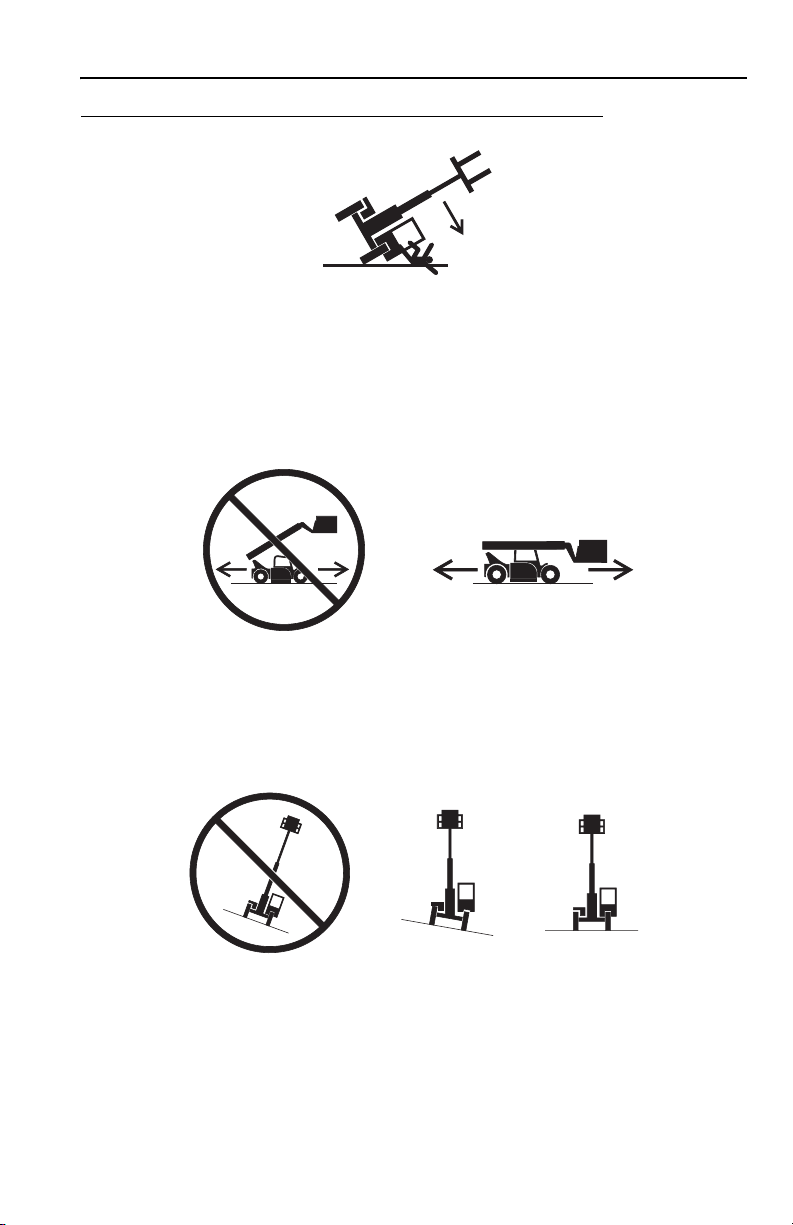
Tip Over Hazard
OW0050
• Never use an attachment without the appropriate JLG supplied capacity chart
installed on the telehandler.
• DO NOT exceed rated lift capacity.
• Be sure that the ground conditions are able to support the machine.
OW0060
• DO NOT drive with boom raised.
• When driving in high speed, use only front wheel steer (if steering modes are
selectable).
OW0080
• DO NOT raise boom unless frame is level (0 degrees).
31200028
1-3
Page 14
Section 1 - General Safety Practices
4 FT
(1,2 M)
OW0100
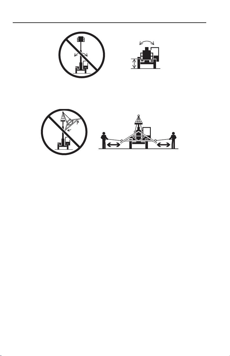
• DO NOT level machine with boom/attachment above 1,2 m (4 ft).
OW0150
• Carry load as low as possible. Tether suspended loads to restrict movement.
• Understand how to properly use the capacity charts located in cab (see
page 4-3).
• Weight of all rigging (slings, etc.) must be included as part of load.
• Start, travel, turn and stop slowly to prevent load from swinging.
• Beware of wind. Wind can cause a suspended load to swing and cause
dangerous side loads - even with tag lines.
• DO NOT attempt to use telehandler frame-leveling to compensate for load swing.
• Keep heavy part of load closest to attachment.
• Never drag the load; lift vertically.
1-4
31200028
Page 15

Section 1 - General Safety Practices
OH2291
• MAINTAIN proper tire pressure at all times. If proper tire pressures are not
maintained, this machine could tip over.
• Refer to manufacturer’s specifications for proper fill ratio and pressure
requirements for tires equipped with ballast.
OH20911
• Always wear the seat belt.
• Keep head, arms, hands, legs and all other body parts inside operator’s cab at all
times.
OH2221
If the telehandler starts to tip over:
• DO NOT JUMP
• BRACE YOURSELF and STAY WITH THE MACHINE
• KEEP YOUR SEAT BELT FASTENED
•HOLD ON FIRMLY
• LEAN AWAY FROM THE POINT OF IMPACT
Trying to escape from a tipping machine could result in death or serious injury.
31200028
1-5
Page 16

Section 1 - General Safety Practices
Travel Hazard
4-Wheel Steer Pivot Steer
• Steering characteristics differ between 4-Wheel Steer & Pivot Steer telehandlers
as shown above. Identify the telehandler you are operating & others on the
jobsite.
• Ensure that adequate clearance is provided between both rear tail swing and
front fork swing.
• Unlike a conventional 4-wheel steer telehandler the rear wheels of a pivot steer
telehandler turn a wider circle than the front wheels.
• Look out for and avoid other personnel, machinery and vehicles in the
area. Use a spotter if you DO NOT have a clear view.
• Before moving be sure of a clear path and sound horn.
• When driving, retract boom and keep boom/attachment as low as possible
while maintaining visibility of mirrors and maximum visibility of path of
travel.
• Always look in the direction of travel.
• Always check boom clearances carefully before driving underneath
overhead obstructions. Position attachment/load to clear obstacles.
OW0120
1-6
31200028
Page 17

Section 1 - General Safety Practices
Load Falling Hazard
OW0130
• Never suspend load from forks or other parts of carriage.
• DO NOT burn or drill holes in fork(s).
• Forks must be centered under load and spaced apart as far as possible.
31200028
1-7
Page 18

Section 1 - General Safety Practices
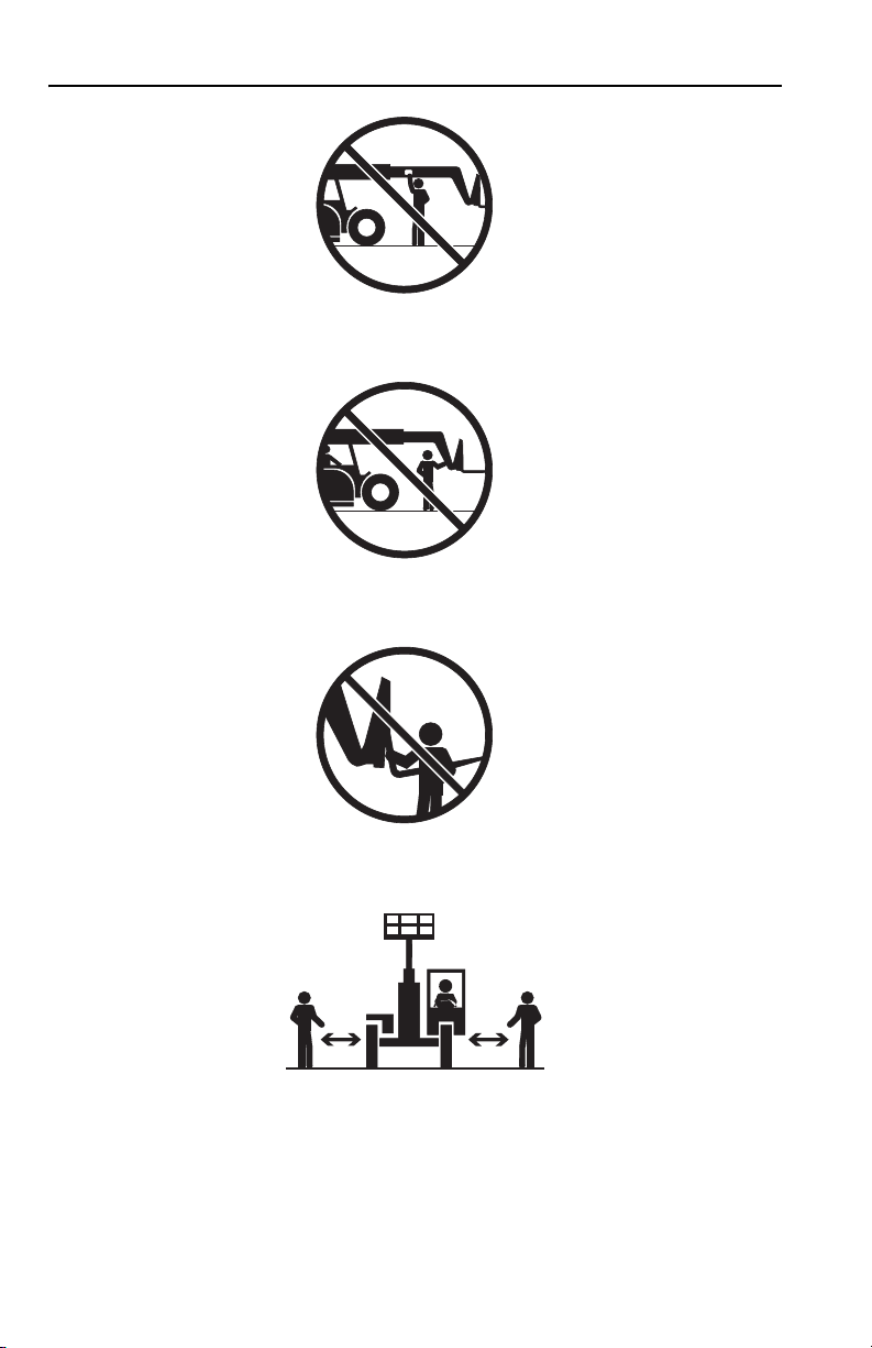
Lifting Personnel
OW0170
• When lifting personnel, USE ONLY a JLG manufactured personnel work
platform, with proper capacity chart displayed in the cab.
OW0190
• DO NOT drive machine from cab when personnel are in platform.
• DO NOT use the personnel work platform until you study & understand the
“capacity chart.” If your telehandler does not have the correct “personnel work
platform capacity chart,” ask your supervisor to get one before using the
attachment.
1-8
31200028
Page 19

Section 1 - General Safety Practices
Preparation and Setup
1. Check to ensure the personnel platform is securely attached at the Quick
Switch™. Follow installation procedure on page 4-7.
2. Ensure the telehandler is on a firm surface and is level.
3. Engage the park brake. Blocking the wheels is also recommended.
4. Level the platform, both side to side (frame sway) and front to back
(attachment tilt).
5. Keep area under the platform free from personnel.
6. DO NOT lift or carry persons in the bucket or on forks.
Never tilt the platform forward, rearward, or sway the machine when the platform is
occupied. Serious injury or death could result.
31200028
1-9
Page 20

Section 1 - General Safety Practices
Driving Hazards On Slopes
OW0200
To maintain sufficient traction and braking capabilities, travel on slopes as follows:
1. When unloaded, the rear of the machine is the “heavy end.” Drive with forks
pointed downhill.
2. When loaded, the front of the machine is the “heavy end.” Drive with the forks
pointed uphill.
• To avoid overspeeding the engine and drivetrain when driving down slopes,
downshift to a lower gear and use the service brake as necessary to maintain a
slow speed. DO NOT shift into neutral and coast downhill.
• Avoid excessively steep slopes or unstable surfaces. To avoid tip over DO NOT
drive across excessively steep slopes under
• Avoid turning on a slope. Never engage “inching” or shift to “Neutral” when going
downhill.
• DO NOT park on a slope.
any
circumstances.
1-10
31200028
Page 21

Section 1 - General Safety Practices
Pinch Points and Crush Hazards
Stay clear of pinch points and rotating parts on the telehandler.
• Stay clear of moving parts while engine is running.
OW0220
• Keep clear of steering tires and frame or other objects.
OW0210
31200028
OW0230
• Keep clear from under boom.
1-11
Page 22
Section 1 - General Safety Practices
• Keep clear of boom holes.
• Keep arms and hands clear of attachment tilt cylinder.
OW0240
OW0250
1-12
OW0260
• Keep hands and fingers clear of carriage and forks.
OW0960
• Keep others away while operating.
31200028
Page 23

Section 1 - General Safety Practices
Fall Hazard
OW0280
• Enter using the proper hand holds and steps provided. Always maintain 3-point
contact when mounting or dismounting. Never grab control levers or steering
wheel when mounting or dismounting the machine.
• DO NOT get off the machine until the shutdown procedure on page 3-4 has been
performed.
OW0290
• DO NOT carry riders. Riders could fall off machine causing death or serious
injury.
31200028
1-13
Page 24

Section 1 - General Safety Practices
Chemical Hazards
Exhaust Fumes
• DO NOT operate machine in an enclosed area without proper ventilation.
• DO NOT operate the machine in hazardous environments unless approved for
that purpose by JLG and site owner. Sparks from the electrical system and the
engine exhaust can cause an explosion.
Flammable Fuel
OW0300
• DO NOT fill the fuel tank or service the fuel system near an open flame, sparks
or smoking materials. Engine fuel is flammable and can cause a fire and/or
explosion.
Hydraulic Fluid
OW0950
• DO NOT attempt to repair or tighten any hydraulic hoses or fittings while the
engine is running or when the hydraulic system is under pressure.
• Stop engine and relieve trapped pressure. Fluid in the hydraulic system is under
enough pressure that it can penetrate the skin.
• DO NOT use your hand to check for leaks. Use a piece of cardboard or paper to
search for leaks. Wear gloves to protect hands from spraying fluid.
1-14
31200028
Page 25

Section 2 - Pre-Operation and Controls
SECTION 2 - PRE-OPERATION AND CONTROLS
2.1 PRE-OPERATION CHECKS & INSPECTION
Note: Complete all required maintenance before operating unit.
WARNING
FALL HAZARD. Use extreme caution when checking items beyond your normal
reach. Use an approved ladder. Failure to comply could result in death or serious
injury.
Walk around inspection must be performed at beginning of each work shift or at
each change of operator.
Ensure all Safety decals are legible and in place. Clean or replace as required. See
“Safety Decals”
Before removing filler caps or fill plugs, wipe all dirt and grease away from the ports.
If dirt enters these ports, it can severely reduce component life.
If spark arrestors are required, be sure they are in place and in good working order.
When adding fluids, refer to lubrication section of this manual to determine proper
type and intervals.
on page 2-6.
31200028
2-1
Page 26
Section 2 - Pre-Operation and Controls
3513 & 4013
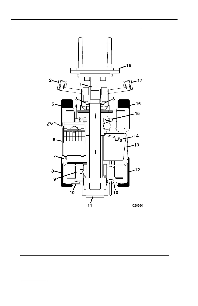
Begin your walk-around inspection at item 1. Continue to your right
(counterclockwise when viewed from top) checking each item in sequence.
INSPECTION NOTE: On all components, make sure there are no loose or missing
parts, that they are securely fastened and no visible leaks or excessive wear exists
in addition to any other criteria mentioned. Inspect all structural members including
attachment for cracks, excessive corrosion and other damage.
1. Boom Sections & Lift, Tilt, Extend/Retract, Compensating (Slave) Cylinders
• Check front, top, side & rear slider pads for adequate grease.
• Pivot pins secure; hydraulic hoses undamaged, not leaking.
2. Left Outrigger
leaking. Pressure switch and proximity switch undamaged and clean.
- Pins secure; hydraulic hoses & cylinder undamaged, not
2-2
-
31200028
Page 27

Section 2 - Pre-Operation and Controls
3. Front Work Lights - Clean, undamaged and work properly.
4. Front Axle
hydraulic hoses undamaged, not leaking.
5. Wheel/Tire Assembly
6. Cab & Electrical
• General appearance; no visible damage; proper load charts and applicable
Operator & Safety manual located in manual holder.
• Window glass undamaged and clean.
• Gauges, switches, joystick, foot controls, park brake & horn operational.
• Check seat belt for damage, replace belt if frayed or cut webbing, damaged
buckles or loose mounting hardware.
• Check brake fluid level, refill as required.
7. Hydraulic Reservoir
be cool); filler/breather cap secure and working.
8. Wheel/Tire Assembly - No loose or missing lug nuts; proper inflation.
9. Rear Axle - Steer cylinders undamaged, not leaking; pivot pins secure;
hydraulic hoses undamaged, not leaking.
10. Rear Work Lights - Clean, undamaged and work properly.
11. Fuel Tank - Check fluid level, refill as required; filler cap is securely fastened.
12. Wheel/Tire Assembly
13. Engine Compartment
• Engine Crankcase and Radiator, check levels & refill as required.
• Drive belts, check condition & replace as required.
• Air cleaner element condition indicator, check for clogged condition. Replace
element as required.
• Main control valve, see inspection note.
• Battery charged, indicator must be green. Cables tight, no visible damage or
corrosion.
• Engine cover properly secured and latched.
14. Mirrors - Clean, undamaged and work properly.
15. Wheel/Tire Assembly
- Steer cylinders undamaged, not leaking; pivot pins secure;
- No loose or missing lug nuts; proper inflation.
-
- Recommended fluid level on sight gauge (lubricant must
- No loose or missing lug nuts; proper inflation.
-
- No loose or missing lug nuts; proper inflation.
16. Sway Cylinder
17. Right Outrigger
leaking. Pressure switch and proximity switch undamaged and clean.
18. Attachment
- Pins secure; hydraulic hoses undamaged, not leaking.
- Pins secure; hydraulic hoses & cylinder undamaged, not
- Properly installed, see
“Attachment Installation”
31200028
on page 4-7.
2-3
Page 28
Section 2 - Pre-Operation and Controls
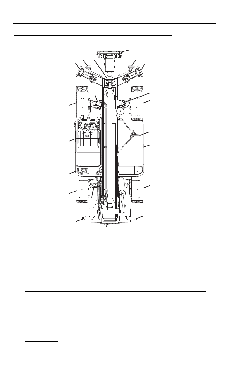
4017
18
2
3
1
2
17
4
5
6
7
8
9
10
11
Begin your walk-around inspection at item 1. Continue to your right
(counterclockwise when viewed from top) checking each item in sequence.
INSPECTION NOTE: On all components, make sure there are no loose or missing
parts, that they are securely fastened and no visible leaks or excessive wear exists
in addition to any other criteria mentioned. Inspect all structural members including
attachment for cracks, excessive corrosion and other damage.
16
15
14
13
12
10
OZ0400
1. Boom Sections & Lift, Tilt, Extend/Retract, Compensating (Slave) Cylinders
• Check front, top, side & rear slider pads for adequate grease.
• Pivot pins secure; hydraulic hoses undamaged, not leaking.
• Check extend/retract chains and adjustment blocks for adequate tension.
2. Front Work Lights
3. Left Outrigger - Pins secure; hydraulic hoses & cylinder undamaged, not
leaking. Pressure switch and proximity switch undamaged and clean.
2-4
- Clean, undamaged and work properly.
31200028
-
Page 29

Section 2 - Pre-Operation and Controls
4. Front Axle - Steer cylinders undamaged, not leaking; pivot pins secure;
hydraulic hoses undamaged, not leaking.
5. Wheel/Tire Assembly
- No loose or missing lug nuts; proper inflation.
6. Cab & Electrical
• General appearance; no visible damage; proper load charts and applicable
Operator & Safety manual located in manual holder.
• Window glass undamaged and clean.
• Gauges, switches, joystick, foot controls, park brake & horn operational.
• Check seat belt for damage, replace belt if frayed or cut webbing, damaged
buckles or loose mounting hardware.
• Check brake fluid level, refill as required.
7. Hydraulic Reservoir
be cool); filler/breather cap secure and working.
8. Wheel/Tire Assembly
9. Rear Axle
hydraulic hoses undamaged, not leaking.
10. Rear Worklights
11. Fuel Tank
12. Wheel/Tire Assembly - No loose or missing lug nuts; proper inflation.
13. Engine Compartment
• Engine Crankcase and Radiator, check levels & refill as required.
• Drive belts, check condition & replace as required.
• Air cleaner element condition indicator, check for clogged condition. Replace
element as required.
• Main control valve, see inspection note.
• Battery charged, light must be green. Cables tight, no visible damage or
corrosion.
• Engine cover properly secured and latched.
14. Mirrors
- Clean, undamaged and work properly.
-
- Recommended fluid level on sight gauge (lubricant must
- No loose or missing lug nuts; proper inflation.
- Steer cylinders undamaged, not leaking; pivot pins secure;
- Clean, undamaged and work properly.
- Check fluid level, refill as required; filler cap is securely fastened.
-
15. Wheel/Tire Assembly
16. Sway Cylinder
17. Right Outrigger
leaking. Pressure switch and proximity switch undamaged and clean.
18. Attachment
- Properly installed, see
- No loose or missing lug nuts; proper inflation.
- Pins secure; hydraulic hoses undamaged, not leaking.
- Pins secure; hydraulic hoses & cylinder undamaged, not
“Attachment Installation”
31200028
on page 4-7.
2-5
Page 30
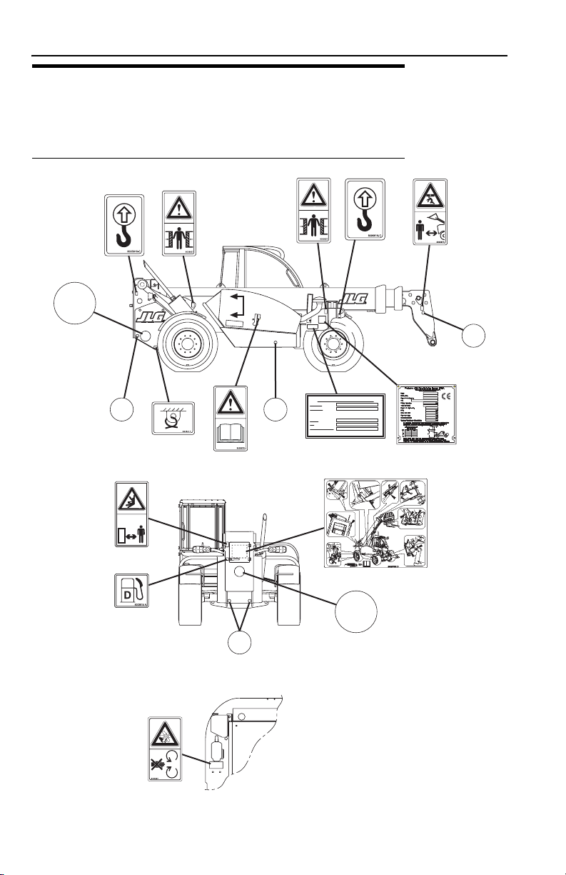
Section 2 - Pre-Operation and Controls
2.2 SAFETY DECALS
Ensure all DANGER, WARNING, CAUTION and instructional decals and proper
capacity charts are legible and in place. Clean and replace as required.
3513 & 4013
35
Optional
8009377 (35)
2603207 (20)
8009890 (22)
8009885 (12)
8005616
8006612
8008657
8005617
8005670
8008657
A
A
80031988003198
8005616
AERIAL PLATFORM APPLICATION
PLATE S/N
TRUCK S/N
This truck can be combined with the aerial platform:
MODEL
P/N
HOMOLOGATION No.
1706628
8005675
8003198
1706227
8008793
2-6
8009815
8005869
3931579
VIEW A-A
35
Optional
8009377 (35)
2603207 (20)
8009890 (22)
8009885 (12)
OZ0960
31200028
Page 31

Section 2 - Pre-Operation and Controls
8005675
B
B
8003198
8008195
8005616
C
C
8005671
8008657
8005671
8003198
8008657
8009816
8005616
8005617
8003198
35
Optional
8009377 (35)
2603207 (20)
8009890 (22)
8009885 (12)
31200028
8006038
VIEW B-B
80056178005617
VIEW C-C
OZ1000
2-7
Page 32

Section 2 - Pre-Operation and Controls
P/N 1170001
P/N 2340029
P/N 4802111
P/N 8008014
OIL
ATF
Dexron
D
2447967
LOAD
CHARTS
4017
14
13
12
11
50°
10
9
40°
EN 1459 B (1998)
8
7
30°
6
5
20°
1.000kg
4
500kg
3
750kg
10°
2
400kg
1
0°
0
8008746 B
m
9
876543210
4017
14
13
12
11
50°
10
9
40°
8
7
30°
6
g
k
0
5
0
20°
g
.0
k
3
g
0
k
4
0
0
0
.0
g
2
g
.5
k
k
3
0
3
0
0
0
.5
10°
.3
g
2
1
k
2
0
0
.5
1
1
0°
0
m
876543210
9
2447 967
8005670
8005671
8005608
8008613
(Optional)
8005609
8005673
P/N 1170001
P/N 2340029
P/N 4802111
P/N 8008014
70°
G
200
0k
60°
g
F
E
D
C
g
k
B
0
g
0
k
0
.
0
4
0
A
0
.
3
g
k
0
0
2.000kg
5
.
3
2.500kg
1.500kg
70°
G
60°
F
E
D
C
EN 1459 B (1998)
B
A
g
k
0
0
.0
4
8008651
8005674
8005671
8005672
8005608
15
1
A
25 26
A
15
2
10 15
AA
3
7.5
A
A
4
7.5
E
R
A
7.5
5
S
A
6
7.5
A
7
7.5
A
7.5
8
A
9
12V
15
A
10
15
ESX
A
25
11
A
12
30
A
15
13
A
10
14
A
15
15
A
20
16
A
17
20
A
18
15
A
19
15
A
20
10
A/C
A
21
25
A
22
25
A
23
10
A
24
7.5
8008196
8008613
Fusecard
8008196_C
L
WA
dB
05
1
1705979
8005609
1705979
1705980
06
1
L
WA
dB
1705980
8005870
8008805
8005870
8h
2-8
VIEW OF
REAR WINDOW
100
%
Load Moment
Indicator
TEST
8h
VIEW OF LOAD
MOMENT INDICATOR
OZ1022
31200028
Page 33

4017
Section 2 - Pre-Operation and Controls
35
8009377
(optional)
8005616
8008657
8005617
8005671
8005671
A
A
8005670
8008657
80031988003198
8005616
8005617
1706227
1706277
31200028
8009815
8005869
3931579
VIEW A-A
35
8009377
(optional)
OZ0860
2-9
Page 34

Section 2 - Pre-Operation and Controls
8005675
8003198
8005616
8008657
8005671
8005671
8006038
8008657
8005616
35
8009377
(optional)
80098168005617
8005617
80031988003198
2-10
8008195 8008195
OZ0870
31200028
Page 35

Section 2 - Pre-Operation and Controls
OIL
ATF
Dexron
D
2447967
LOAD
CHARTS
4017
14
13
12
11
50°
10
9
40°
EN 1459 B (1998)
8
7
30°
6
5
20°
1.000kg
4
500kg
3
750kg
10°
2
400kg
1
0°
0
8008746 B
m
9
876543210
4017
P/N 1170001
P/N 2340029
P/N 4802111
P/N 8008014
14
13
12
11
50°
10
9
40°
8
7
30°
6
g
k
0
5
0
20°
g
.0
k
3
g
0
k
4
0
0
0
.0
g
2
g
.5
k
k
3
0
3
0
0
0
.5
10°
.3
g
2
1
k
2
0
0
.5
1
1
0°
0
m
876543210
9
2447 967
8005670
60°
2.000kg
2.500kg
1.500kg
60°
g
k
0
0
.0
4
P/N 1170001
P/N 2340029
P/N 4802111
P/N 8008014
70°
G
2
00
0k
g
F
E
D
C
g
k
B
0
g
0
k
0
.
0
4
0
A
0
.
3
g
k
0
0
5
.
3
70°
G
F
E
D
C
EN 1459 B (1998)
B
A
8005870
8005673
8008651
8005870
8005671
8005674
8005608 8005609
8005671
8005672
(Optional)
8005608
1
15
A
25 26
A
2
15
10 15
AA
3
7.5
A
A
4
7.5
E
R
A
5
7.5
S
A
6
7.5
A
7
7.5
A
8
7.5
A
9
15
12V
A
10
15
ESX
A
11
25
A
12
30
A
13
15
A
14
10
A
15
15
A
16
20
A
17
20
A
18
15
A
19
15
A
20
10
A/C
A
21
25
A
22
25
A
23
10
A
24
7.5
8008196
8008613
Fusecard
8008196C
8008805
8h
8008613
L
06
1
1705980
WA
dB
8005609
1705980
31200028
VIEW OF
REAR WINDOW
VIEW OF PARK
BRAKE LEVER
100
%
Load Moment
Indicator
TEST
8h
VIEW OF LOAD
MOMENT INDICATOR
1706209
OZ0883
2-11
Page 36

Section 2 - Pre-Operation and Controls
This Page Intentionally Left Blank
2-12
31200028
Page 37

Section 2 - Pre-Operation and Controls
2.3 OPERATOR CAB
The telehandler is equipped with an enclosed FOPS/ROPS cab.
WARNING
Never operate telehandler unless the overhead guard and cab structure are in
good condition. Any modification to this machine must be approved by JLG to
assure compliance with FOPS/ROPS certification for this cab/machine
configuration. If damaged, the CAB CANNOT BE REPAIRED. It must be
REPLACED.
31200028
2-13
Page 38

Section 2 - Pre-Operation and Controls
2.4 CONTROLS
1. Parking Brake: See page 2-23 for details.
2. Accelerator Pedal: Pressing down the pedal increases engine and hydraulic
speed.
3. Service Brake Pedal: The further the pedal is depressed, the slower the travel
speed.
4. Steering Column Adjuster
5. Wipers, Lights, Turn Signal Lever
6. Transmission Control Lever: See page 2-24 for details.
2-14
: See page 2-27 for details.
: See page 2-26 for details.
31200028
Page 39

Section 2 - Pre-Operation and Controls
7. Round Air Vents: Three individually adjustable round vents.
8. Brake Fluid Reservoir
MAX marks. The sight gauge is on the left side of the reservoir.
9. Air Louvers
10. Instrument Panel
the output of the machine. See page 2-16 for details.
11. Level Indicator
of the telehandler.
12. Fuel Gauge
13. Load Moment Indicator
14. Engine Temperature Gauge
coolant temperature of 102°C (221°F). Stop immediately and allow the engine
to run at idle in order to cool. (See engine manual.)
15. Control & Indicator Console
16. Hazard Flashers: Press button to activate, press button to deactivate.
17. Ignition
18. Joystick
19. Continuous Hydraulic Powered Attachment Operation Button: Press button for
continuous operation of hydraulic powered attachment. See Section
4 - Attachments & Hitch Options for approved attachments and control
instructions.
: Four individually adjustable air louvers.
: Gauge for the diesel fuel tank.
: Key activated. See page 2-22 for details.
: See page 2-28 for details.
: The brake fluid level should be between the MIN and
: Controls and indicates some machine functions and displays
: Enables the operator to determine the left to right level condition
: See page 2-32 for details.
: At high working load do not exceed the critical
: See page 2-33 for details.
20. Auxiliary Hydraulic Circuit/Hydraulic Quick-Switch Button: Press button to select
the desired auxiliary hydraulic circuit. See Section 4 - Attachments & Hitch
Options for approved attachments and control instructions.
21. 12 V Receptacle
22. Heater and Air Conditioner Controls
23. Emergency Stop Switch
ERS.
31200028
: Supplies power for service laptop, light, etc.
: See page 2-34 for details.
: Push to stop engine operation. Shuts off power to the
2-15
Page 40

Section 2 - Pre-Operation and Controls
Instrument Panel
10
3
4
OK
!
9
8
OZ0020
2
C
1
12
1. Steer Mode Selection
LED lit while activated. Blinks during change to another steer mode.
See page 2-35 for details.
2. C Key
Returns user interface one level during navigation and deletes user inputs.
3. Up/Down Arrows
Scroll up and down in the user interface.
11
5
6
7
4. OK Key
Confirms user interface inputs.
5. Overload Protection Override
When the button is activated the LED lights and the buzzer sounds. The
automatic overload protection function (see page 2-32) is disabled. Push button
or cycle ignition switch to re-enable function.
WARNING
TIP OVER HAZARD. Exceeding lift capacity of the telehandler could damage the
equipment and/or cause tip over resulting in death or serious injury.
6. Declutch Shutoff
With the LED not lit, the transmission is in neutral and all power is routed to the
hydraulic system when the service brake is depressed. Function is deactivated
when LED is lit.
2-16
31200028
Page 41

Section 2 - Pre-Operation and Controls
7. Road Use Operation
LED lit while activated: The outrigger, boom, sway and auxiliary hydraulic
systems are disengaged. No functions can be operated with the joystick.
The Declutch Shutoff is not lit and Front-Wheel Steer Mode must be active to
proceed to Road Use Operation.
Note: Activate this function before traveling on public roads. See “Road Operation”
on page 3-8.
8. Warning Indicator
The RED LED illuminates for high priority problems.
• Engine Oil Pressure
• Engine Temperature
• Transmission Temperature
•Air Filter
• Hydraulic Oil Filter
• CAN Bus
• Engine Speed Sensor
• Hydraulic Pump Pressure
• Short Circuit Main Control Valve
• Boom Angle Sensor
• Platform Mode Fault
• Platform CAN Fault
CAUTION
EQUIPMENT DAMAGE. When the red LED illuminates and a warning tone is
heard, immediately bring machine to a stop, lower boom and attachment to
ground and stop the engine. Determine cause before continued use.
9. Auxiliary Hydraulic Indicator
Attachment hydraulic system in continuous operating mode when LED is lit.
(e.g. street sweeper)
10. Display Screen
Displays Operating Status, Fault Codes and Service Codes. See page 2-18 for
details.
11. Anti Theft Device Indicator
LED lit while actived: Enter the anti theft code. Refer to page 2-21 for details.
12. Service Indicator
Indicates a maintenance interval when LED is lit. Service is required.
31200028
2-17
Page 42

Section 2 - Pre-Operation and Controls
Display Screen
1
0
km/h
718
0
1
min
3
4
2
P
The display screen consists of five sections:
1. Speed Indicator (km/h)
2. Symbol Display
3. Engine Speed Indicator (rpm)
4. Operating Hours Indicator (Bh)
5. Boom Angle, Aux Hydraulic and Common Message Display
Symbol Display (Section 2)
a. Parking Brake
Displayed permanently when parking brake is applied (see
page 2-23). Parking brake must be applied to start engine.
Symbol will flash when parking brake is not applied and
attempting to start engine.
b. Glow Indicator
Displayed when ignition key is in position-1; engine
preheat. Symbol is shown until start temperature is
reached. After the symbol disappears, the engine can be
started, do not start before.
c. Diagnostic Startup
Displayed after system start, while startup diagnostic is in
progress. Symbol is shown until startup diagnostics has
been successfully completed. If the symbol does not
disappear, a failure has been detected within the
diagnosis. Stop engine immediately.
d. Engine Oil Pressure
Symbol displayed and buzzer sounds when low oil
pressure exists. Stop engine immediately.
12
°
5
OZ0030
P
OH2480
OU0040
OZ1150
OT1010
2-18
31200028
Page 43

Section 2 - Pre-Operation and Controls
e. Engine Temperature
Symbol displayed and buzzer sounds when engine oil
temperature is too high. Stop engine immediately.
f. Transmission Temperature
Symbol displayed and buzzer sounds when transmission
temperature is too high. Stop engine immediately.
g. Air Filter
Symbol displayed and buzzer sounds when air filter is
clogged. Stop engine immediately.
h. Hydraulic Oil Filter
Symbol displayed when the hydraulic oil filter requires
cleaning. Stop engine immediately.
i. CAN Bus
Symbol displayed when there is a component failure. Stop
engine immediately.
j. Engine Speed Sensor
Symbol displays when engine speed is too low (faulty
engine speed signal). Stop engine immediately.
k. Main Hydraulic Pump Pressure
Symbol displayed when there is low hydraulic oil pressure.
Only emergency steering is available. Stop engine
immediately.
l. Short Circuit Main Control Valve
Symbol displayed and buzzer sounds when voltage to the
main control valve is out of range. Stop engine
immediately.
m. Boom Angle Sensor
Symbol displayed and buzzer sounds when the boom
angle is lower or higher than the allowed value. Retract
and lower boom immediately.
n. Mode Fault
Symbol displayed and buzzer sounds when platform
voltage is out of range. Retract and lower boom
immediately. If joystick functions do not respond, shut off
engine and restart to clear fault.
o. Platform CAN Fault
Symbol displayed and buzzer sounds when the platform
joystick has not communicated for three seconds. Retract
and lower boom immediately.
OZ0250
OT0990
OZ0260
OT1030
OZ0270
OZ0250
OZ0290
OZ0310
OZ0340
OZ1160
OZ1170
31200028
2-19
Page 44

Section 2 - Pre-Operation and Controls
Boom Angle, Auxiliary Hydraulic & Message Window (Section 5)
a. Boom Angle Indicator
Displays the boom angle in degrees.
(0 degrees indicates horizontal)
b. Auxiliary Hydraulics
When the permanent auxiliary hydraulic function is active, the display
shows the percentage value (-100% to +100%) of the auxiliary hydraulic for
30 seconds. Also displays for 30 seconds at each change. See Section
4 - Attachments & Hitch Options for details.
c. Message Window
Code Entry - Anti Theft Device: Driver must enter four-digit code after
system start. See page 2-21 for details.
Hardware-exchange: After a hardware exchange has occurred, the
hardware-display will appear for 30 seconds. Pressing the OK button within
those 30 seconds will access the hardware exchange menu.
Service: Service messages will be displayed after start-up for 30 seconds
when a given service time interval elapses. Pressing the OK button within
those 30 seconds will allow the driver to verify if the service has been
completed.
User Interface - Level 1
To access the menu hold the OK key down for 2 seconds.
OZ0330
• Language
• Anti Theft Device
• Operating Modes
• Diagnostics
• Fault Memory
• Service Display
• Vehicle Data
Note: Access authorization (a numeric code) is required to view Levels 2 and 3.
2-20
31200028
Page 45

Section 2 - Pre-Operation and Controls
Anti Theft Device
The anti theft device requires entering a numeric code for operation to prevent
unauthorized use.
Button Values
6
5
4
7
C
3
2
1
OK
8
9
0
!
OZ0350
Changing the Anti Theft Code
The anti theft device is set to a numeric code of 0000 when delivered from the
factory. To prevent unauthorized access change the code upon first use.
1. Turn on the ignition key and wait for the LEDs to go out.
2. Press the OK button for 2 seconds to access the user interface.
3. Using the arrow buttons, move to and select the Anti Theft Device menu item.
Select modify code.
4. Enter the old code. (e.g. 0000) and within 30 seconds enter the new code (e.g.
7777). Confirm with the OK button.
Note: Memorize the new code. Without the access code, the assistance of JLG
Customer Service will be required to start the telehandler.
Activating/Deactivating the Anti Theft Device
1. Turn on the ignition key and wait for the LEDs to go out.
2. Press the OK button for 2 seconds to access the user interface.
3. Using the arrow buttons, move to and select Vehicle Data.
4. Select Display
5. Select Configuration.
6. Use the arrow keys to select Anti Theft Device. Activate or deactivate the anti
theft device as desired. Confirm selection with the OK button.
7. Exit menu by holding the OK key.
31200028
2-21
Page 46

Section 2 - Pre-Operation and Controls
Ignition
0
P
•Position 0 - Engine off
•Position I - Voltage is available for all electrical functions.
•Position II - Engine preheat at temperature below 0°C. Wait until icon on display
screen goes out.
•Position III - Engine start.
•Position P - Accessory position, power is transferred to the platform.
I
II
III
OZ1100
2-22
31200028
Page 47

Section 2 - Pre-Operation and Controls
Park Brake
3513 & 4013 4017
• The Park Brake Lever (1) controls the application and release of the park brake.
• Pull back to activate.
• Push forward to deactivate.
WARNING
MACHINE ROLL-AWAY HAZARD. Always move park brake lever to "ON"
position, lower boom to ground and stop engine before leaving cab. Machine
roll-away could cause death or serious injury.
WARNING
CRUSH HAZARD. Turning engine off applies the park brake. Applying park brake
or turning engine off while traveling will cause unit to stop abruptly and could
cause load loss, resulting in death or serious injury. Either may be used in an
emergency situation.
Parking Procedure
1. Using service brake, stop telehandler in an appropriate parking area.
2. Follow
31200028
“Shut-Down Procedure”
on page 3-4.
2-23
Page 48

Section 2 - Pre-Operation and Controls
Transmission Control
Direction of Travel Selection
2
1
3
OZ0060
•This lever (1) engages forward or reverse travel. Push lever forward (2) for
forward travel; pull lever rearward (3) for reverse travel. Move lever to centered
position for ‘Neutral’.
• Forward or reverse travel can be selected while in any gear.
• When traveling in reverse, the back-up alarm will automatically sound.
• Drive in reverse and turn only at slow rates of speed.
• Do not increase engine speed with the transmission in forward or reverse and the
service brake depressed in an attempt to get quicker hydraulic performances.
This could cause unexpected machine movement.
WARNING
TIP OVER/CRUSH HAZARD. Bring telehandler to a complete stop before
shifting transmission control lever. A sudden change in direction of travel could
reduce stability and/or cause load to shift or fall. Failure to comply could result in
death or serious injury.
2-24
31200028
Page 49

Section 2 - Pre-Operation and Controls
Gear Selection
4
OZ0070
• Gear selection is located on the twist grip handle (4) of transmission control lever.
Twist hand grip to select gear.
• Select the appropriate gear for the task being performed. Use a lower gear
when transporting a load. Use a higher gear only when driving unloaded for
longer distances.
• Slow down prior to downshifting. Do not downshift more than one gear at a
time.
Neutral Lock Lever
5
6
7
OZ0080
• To lock the transmission control lever in the neutral position, place the
transmission control lever in the neutral position and move the neutral lock lever
(5) the “N” position (6).
• To unlock, move the neutral lock lever to the “D” position (7).
31200028
2-25
Page 50

Section 2 - Pre-Operation and Controls
Wiper, Lights and Turn Signal Control Lever
1. Flash-to-Pass: Pull the lever back completely. The high beam indicator will light.
2. High/Low Beam
The high beam indicator will light when the high beam lights are on.
3. Left Turn Signal
4. Right Turn Signal
5. Horn: Push the button.
: With the lights on, pull the lever to switch to high or low beam.
: Push the lever forward.
: Pull the lever backward.
6. Windshield Washer
7. Windshield Wiper
or “I”-Continuous.
2-26
: Slide the sleeve toward the steering column.
: Rotate the sleeve to the desired setting, “O”-Off, “J”-Interval
31200028
Page 51

Steering Column Adjuster
Section 2 - Pre-Operation and Controls
•Follow
• Loosen the knob (8).
• Place the steering column in the desired position.
• Retighten the knob.
“Shut-Down Procedure”
on page 3-4.
WARNING
TIP OVER/CRUSH HAZARD. Bring telehandler to a complete stop and shutdown
engine before adjusting steering column. A sudden change in direction of travel
could reduce stability and/or cause load to shift or fall. Failure to comply could
result in death or serious injury.
31200028
2-27
Page 52

Section 2 - Pre-Operation and Controls
Joystick
Standard Controls
The joystick (1) controls the boom, attachment and outrigger functions.
Boom Functions
• Move the joystick back to lift boom; move joystick forward to lower boom; move
joystick right to extend boom; move joystick left to retract boom.
• The speed of boom functions depends upon the amount of joystick travel in
corresponding direction. Increasing engine speed will also increase function
speed.
• For two simultaneous boom functions, move the joystick between quadrants. For
example; moving the joystick forward and to the left will lower and retract boom
simultaneously.
WARNING
TIP OVER/CRUSH HAZARD. Rapid, jerky operation of controls will cause rapid,
jerky movement of the load. Such movements could cause the load to shift or fall
or could cause the machine to tip over. Failure to comply could result in death or
serious injury.
2-28
31200028
Page 53

Section 2 - Pre-Operation and Controls
Attachment Functions
• Attachment tilt is control by the rocker switch (2). Push the rocker switch up to tilt
attachment forward (down); push the rocker switch down to tilt attachment back
(up).
• Auxiliary Hydraulics (optional) button (6) controls function of attachments that
require hydraulic supply for operation. See Section 4 - Attachments & Hitch
Options for approved attachments and control instructions.
Outrigger Functions
• Button (3) controls the left outrigger. Press and hold the button; move the joystick
forward to lower the outrigger; move the joystick back to raise the outrigger.
• Button (5) controls the right outrigger. Press and hold the button; move the
joystick forward to lower the outrigger; move the joystick back to raise the
outrigger.
• Button (4) controls both outriggers simultaneously. Press and hold the button;
move the joystick forward to lower the outriggers; move the joystick back to raise
the outriggers.
WARNING
TIP OVER HAZARD. Outriggers increase stability and load capacity only if they
are used properly. Using outriggers on soft surfaces could cause telehandler to
tip over and result in death or serious injury. Always ensure surface can support
telehandler and load.
31200028
2-29
Page 54

Section 2 - Pre-Operation and Controls
Optional Controls
4
3
1
2
The joystick (1) controls the boom, attachment and outrigger functions.
Boom Functions
• Move the joystick back to lift boom; move joystick forward to lower boom.
• Boom extend/retract is controlled by the rocker switch (2). Push the rocker switch
up to extend boom; push the rocker switch down to retract boom.
• The speed of boom functions depends upon the amount of joystick travel in
corresponding direction. Increasing engine speed will also increase function
speed.
• For two simultaneous boom functions, move the joystick between quadrants. For
example; moving the joystick forward and to the left will lower boom and tilt
attachment back (up) simultaneously.
5
6
OZ1900
WARNING
TIP OVER/CRUSH HAZARD. Rapid, jerky operation of controls will cause rapid,
jerky movement of the load. Such movements could cause the load to shift or fall
or could cause the machine to tip over. Failure to comply could result in death or
serious injury.
2-30
31200028
Page 55

Section 2 - Pre-Operation and Controls
Attachment Functions
• Move the joystick right to tilt attachment forward (down); move joystick left to tilt
attachment back (up).
• Auxiliary Hydraulics (optional) button (6) controls function of attachments that
require hydraulic supply for operation. See Section 4 - Attachments & Hitch
Options for approved attachments and control instructions.
Outrigger Functions
• Button (3) controls the left outrigger. Press and hold the button; move the joystick
forward to lower the outrigger; move the joystick back to raise the outrigger.
• Button (5) controls the right outrigger. Press and hold the button; move the
joystick forward to lower the outrigger; move the joystick back to raise the
outrigger.
• Button (4) controls both outriggers simultaneously. Press and hold the button;
move the joystick forward to lower the outriggers; move the joystick back to raise
the outriggers.
WARNING
TIP OVER HAZARD. Outriggers increase stability and load capacity only if they
are used properly. Using outriggers on soft surfaces could cause telehandler to
tip over and result in death or serious injury. Always ensure surface can support
telehandler and load.
31200028
2-31
Page 56

Section 2 - Pre-Operation and Controls
Load Moment Indicator (LMI)
The Load Moment Indicator (1) provides a visual indication for forward stability
limitations.
• All five LEDs (2) will light (three green, yellow & red) and the warning buzzer
sounds as the telehandler reaches its forward stability limitations.
• When the red LED is illuminated the automatic overload protection function is
activated. Boom extension, boom lower and outrigger functions are disabled.
• Test the Load Moment Indicator (3) at the beginning of each work shift. See
Section 7 - Additional Checks.
2-32
31200028
Page 57

Section 2 - Pre-Operation and Controls
Control & Indicator Console
Controls and indicates the electrical accessories of the telehandler.
4. High Beam Indicator
5. Battery Charge Indicator
6. Telehandler Turn Signal Indicator
7. Trailer Turn Signal Indicator
8. Rear Work Light Switch
9. Boom Work Light Switch
10. Rear Wiper Switch
on until the key is released.
11. Rotating Beacon Switch
beacon on the cab roof. Power is supplied by a 12V receptacle at the left rear
part of the cab roof.
12. Frame Sway
sway frame left; press right side of switch to sway frame right.
Note: Frame Sway is inoperable with boom angle greater than 20 degrees.
13. Front Work Light Switch (optional)
14. Driving Lights Switch
15. Platform Ready Indicator
: Controls the left to right frame sway. Press left side of switch to
: Illuminates when high beam lights are on.
: Illuminates when battery is at low charge.
(optional)
: Press and hold for 2 seconds or more to turn on. Remains
(optional): Place the magnetic base of the rotating
31200028
2-33
Page 58

Section 2 - Pre-Operation and Controls
Heater and Air Conditioner (optional) Controls
1. Fan Speed: 3-position rotary switch for heater and air conditioner.
2. Temperature Control
3. Air Conditioner (optional): On/Off switch.
4. Recirculate
performance. In this mode no outside air is drawn into the cab.
5. Round Vent
6. Air Louver
Heater
Turn the temperature control to the desired temperature and set the fan speed.
Adjust the air flow through the air louvers and round vents.
Air Conditioner (optional)
Turn on the air conditioner and set the fan speed. Activate the recirculation control to
cool the cab more quickly. Adjust the air flow through the air louvers and round
vents.
Note: When the windows are misted over, run the air conditioner and heater at the
same time.
Defrosting
Direct the flow of air through the louvers and the left front round vent toward the
windshield. Close the other two round vents.
(optional): On/Off switch used for optimum air conditioner
: Adjustable rotary switch.
2-34
31200028
Page 59

Section 2 - Pre-Operation and Controls
2.5 STEER MODES
Stop the telehandler before changing steering modes. An LED will indicate the
steering mode selected.
All-Wheel Steer
C
OZ0180
Front-Wheel Steer
Note: This mode is required for travel on public roads.
C
Crab Steer
31200028
OZ0190
C
OZ0200
2-35
Page 60

Section 2 - Pre-Operation and Controls
2.6 OPERATOR SEAT
Adjustments
1
2
5
6
34
Prior to starting the engine adjust seat for position and comfort as follows:
Fore/Aft
Use the handle (1) to move seat fore and aft.
Height
Use the knob (2) to adjust the height of the seat.
Suspension
Use the knob (3) to adjust the suspension to the appropriate weight setting (4).
Backrest
Use knob (5) to adjust backrest angle.
Seat Belt
Always fasten seat belt (6) during operation.
OZ0830
2-36
31200028
Page 61

Section 2 - Pre-Operation and Controls
Seat Belt
OH20912
Fasten seat belt as follows:
1. Grasp both free ends of the belt making certain that belt webbing is not twisted
or entangled.
2. With back straight in the seat, couple the retractable end (male end) of the belt
into the receptacle (buckle) end of the belt.
3. With belt buckle positioned as low on the body as possible, pull the retractable
end of the belt away from the buckle until it is tight across the lap.
4. To release belt latch, depress red button on the buckle and pull free end from
buckle.
31200028
2-37
Page 62

Section 2 - Pre-Operation and Controls
2.7 MIRRORS & WINDOWS
Keep all windows and mirrors clean and unobstructed.
Cab Door Window
1
2
OZ0210
• During operation the window must either be latched open or closed.
• Open the cab door window (1) and secure it in the latch.
• Press the release button (2) inside the cab to unlatch the window.
Rear Window
4
• Lift lever (3) and push to open the rear window (4).
• Lift lever and pull to close.
2-38
3
OZ0220
31200028
Page 63

Section 2 - Pre-Operation and Controls
Mirrors
5
OZ1680
• Adjust mirrors (5) as required for maximum visibility, before and during operation.
31200028
2-39
Page 64

Section 2 - Pre-Operation and Controls
2.8 HOOD
• To close the hood, slide the gas cylinder lock (1) to one side.
• Close and secure the hood.
2-40
31200028
Page 65

Section 3 - Operation
SECTION 3 - OPERATION
3.1 WARM-UP AND OPERATIONAL CHECKS
This section outlines the checks to be performed at the beginning of each work shift
or at each change of operator.
During warm-up period, check:
1. Heater, defroster and windshield wiper (if equipped).
2. Check all lighting systems (if equipped) for proper operation.
WARNING
CUT/CRUSH/BURN HAZARD. Keep engine cover closed while engine is running
except when checking transmission oil level and hydraulic filter condition
indicator (if equipped). Failure to comply could result in death or serious injury.
When engine warms, check:
1. Transmission fluid level.
2. Service brake and parking brake operation.
3. Forward and reverse travel.
4. Each gear.
5. Steering in both directions with engine at low idle (steering lock to lock will not
be reached). Check in each steering mode.
6. Horn and back-up alarm. Must be audible from inside operators cab with engine
running.
7. All boom and attachment functions - operate smoothly and correctly.
8. Perform any additional checks described in Section 7.
31200028
3-1
Page 66

Section 3 - Operation
3.2 ENGINE
Starting the Engine
This machine can be operated in temperatures of -20°C to 40°C (0°F to 104°F).
Consult JLG for operation outside this range.
1. If equipped, turn on the battery disconnect switch located in engine
compartment.
2. Make sure all controls are in “Neutral” and all electrical components (lights,
heater, defroster, etc.) are turned off. Set parking brake and ensure emergency
stop button is pulled out.
3. Turn ignition switch to position I. Wait approximately four seconds as the control
system performs diagnostics as indicated by “DIAG” and hourglass symbols on
the display. Enter anti theft code if anti theft device is activated.
4. Turn ignition switch to the position II. If temperature is below 0°C, wait for
preheat symbol on display to disappear.
5. Turn ignition switch to position III to engage starting motor. Release key
immediately when engine starts. If engine fails to start within 20 seconds,
release key and allow starting motor to cool a few minutes before trying again.
Note: After engine starts, all controls are inoperable for four seconds while
diagnostics are run.
6. After engine starts, if engine oil pressure does not rise for more than ten
seconds, the engine oil pressure symbol will show on display screen and buzzer
will sound. Stop engine and determine cause before restarting engine.
Reference engine manual for minimum pressure at operating temperature.
7. Warm up engine at approximately 1/2 throttle.
Note: Engine will not start unless transmission control lever is in “Neutral” and park
brake is applied.
WARNING
UNEXPECTED MOVEMENT HAZARD. Always ensure that transmission control
lever is in neutral and the service brake is applied before releasing park brake.
Releasing park brake in either forward or reverse could cause the machine to
move abruptly, causing an accident resulting in death or serious injury.
CAUTION
ENGINE EXPLOSION. Do not spray ether into air intake for cold weather
starting. Failure to comply could result in death or serious injury.
3-2
31200028
Page 67

Section 3 - Operation
Battery Boosted Starting
OW0530
If battery-boost starting (jump-start) is necessary, proceed as follows:
• Never allow vehicles to touch.
• Connect the positive (+) jumper cable to positive (+) post of discharged battery.
• Connect the opposite end of positive (+) jumper cable to positive (+) post of
booster battery.
• Connect the negative (-) jumper cable to negative (-) post on booster battery.
• Connect opposite end of negative (-) jumper cable to ground point on machine
away from discharged battery.
• Follow standard starting procedures.
• Remove cables in reverse order after machine has started.
WARNING
BATTERY EXPLOSION HAZARD. Never jump start or charge a frozen battery
as it could explode. Keep sparks, flames and lighted smoking materials away
from the battery. Lead acid batteries generate explosive gases when charging.
Wear safety glasses. Failure to comply could result in death or serious injury.
31200028
3-3
Page 68

Section 3 - Operation
Normal Engine Operation
• Observe gauges and display screen frequently to be sure all engine systems are
functioning properly.
• Be alert for unusual noises or vibration. When an unusual condition is
noticed, park machine in safe position and perform shut-down procedure. See
“Shut-Down Procedure”
personnel.
• Avoid prolonged idling. If the engine is not being used, turn it off.
. Report condition to your supervisor or maintenance
Shut-Down Procedure
When parking the telehandler, park in a safe location on flat level ground and away
from other equipment and/or traffic lanes.
1. Apply the park brake.
2. Shift the transmission to “Neutral.”
3. Lower forks or attachment to the ground.
4. Operate engine at low idle for 3 to 5 minutes. DO NOT over rev engine.
5. Shut off engine and remove ignition key.
6. Depress emergency stop button.
7. Exit telehandler properly.
8. Turn off electrical master switch in engine compartment (if equipped).
9. Block wheels (if necessary).
3-4
31200028
Page 69

Section 3 - Operation
3.3 OPERATING WITH A LOAD
Lift Load Safely
• You must know the weight and load center of every load you lift. If you are not
sure of the weight and load center, check with your supervisor or with the
supplier of the material.
WARNING
TIP OVER HAZARD. Exceeding lift capacity of the telehandler could damage the
equipment and/or cause tip over resulting in death or serious injury.
• Know the rated load capacities (refer to Section 4) of the telehandler to
determine the operating range in which you can safely lift, transport and place a
load.
Before Picking Up A Load
• Note the conditions of the terrain. Adjust travel speed and reduce amount of load
if conditions warrant.
• Avoid lifting double-tiered loads.
• Make sure load is clear of any adjacent obstacles.
• Adjust spacing of forks so they engage the pallet or load at maximum width. See
“Adjusting/Moving Forks”
• Approach load slowly and squarely with fork tips straight and level. NEVER
attempt to lift a load with just one fork.
• NEVER operate telehandler without a proper and legible Capacity Chart in the
operator’s cab for the telehandler/attachment combination you are using.
on page 4-11.
31200028
3-5
Page 70

Section 3 - Operation
Transporting The Load
OW0540
After engaging the load and resting it against the backrest, tilt the load back to
position it for travel. Travel in accordance with the requirements set forth in Section
1 - General Safety Practices and Section 4 - Attachments & Hitch Options.
Leveling Procedure
1. Position machine in best location to lift or place load.
2. Apply parking brake and move transmission control lever to NEUTRAL.
3. Move boom/attachment to 1,2 m (4 ft) off ground.
4. Observe level indicator to determine whether machine must be leveled and level
machine with switch, see page 2-33 for details.
Important things to remember:
• Never raise the boom/attachment more than 1,2 m (4 ft) above ground unless
telehandler is level.
• The combination of side sway and load could cause the telehandler to tip over.
The telehandler is designed to permit swaying the main frame 9° to left or right to
compensate for uneven ground conditions.
3-6
31200028
Page 71

Section 3 - Operation
Placing The Load
Before placing any load be sure that:
• The landing point can safely support the weight of the load.
• The landing point is level; front to back and side to side.
• Use the capacity chart (see page 4-3) to determine safe boom extension range.
• Align forks at the level load is to be placed, then extend boom slowly until load is
just above area where it is to be placed.
• Lower the boom until the load rests in position and the forks are free to retract.
Disengaging The Load
Once the load has been placed safely at the landing point, proceed as follows:
1. With the forks free from the weight of the load, the boom can be retracted
and/or the telehandler can be backed away from under the load if surface will
not change level condition of telehandler.
2. Lower the carriage.
3. The telehandler can now be driven from the landing location to continue work.
31200028
3-7
Page 72

Section 3 - Operation
3.4 ROAD OPERATION
1. Preparation
a. Empty bucket.
b. Remove any large amounts of dirt from machine
c. Check lights and mirrors and adjust if necessary.
d. Safety equipment to be carried: Warning Triangle, First Aid Kit and Chock.
2. Lower boom. Front edge of attachment should be approximately 30-40 cm
(12-16 in) above the ground.
3. Fully tilt attachment back
4. Place protective shield over front bucket edge; remove or reposition carriage
forks toward the machine and secure to the carriage.
C
1
OK
2
!
OZ0380
5. Select front wheel steering by pressing button (1) on the display panel. This
mode is required for road travel.
6. Select road use button (2) to disable all joystick controlled functions.
7. Machine is now ready for road operation.
Note: Be sure to follow all local and federal/provincial traffic regulations.
3-8
31200028
Page 73

Section 3 - Operation
3.5 LOADING AND SECURING FOR TRANSPORT
WITH PLATFORM
ATTACHED
1. Level the telehandler prior to loading.
2. Using a spotter, load the telehandler with boom as low as possible.
3. Once loaded, apply parking brake and lower boom until boom or attachment is
resting on deck. Move all controls to “Neutral,” stop engine and remove ignition
key.
4. Secure machine to deck by passing chains through the designated tie down
points as shown in the figure.
5. Secure platform with strap as shown in the figure.
6. Do not tie down front of boom.
Note: The user assumes all responsibility for choosing the proper method of
transportation and tie-down devices, making sure the equipment used is capable of
supporting the weight of the vehicle being transported and that all manufacturer’s
instructions and warnings, regulations and safety rules of their employer, and all
local and federal/provincial laws are followed.
8005617 8005617
OZ1691
WARNING
TELEHANDLER SLIDE HAZARD. Before loading telehandler for transport,
make sure deck, ramps and telehandler wheels are free of mud, snow and ice.
Failure to do so could cause telehandler to slide, resulting in an accident causing
serious injury or death.
31200028
3-9
Page 74

Section 3 - Operation
This Page Intentionally Left Blank
3-10
31200028
Page 75

Section 4 - Attachments & Hitch Options
SECTION 4 - ATTACHMENTS & HITCH OPTIONS
4.1 APPROVED ATTACHMENTS
To determine if an attachment is approved for use on the specific telehandler you are
using, perform the following prior to installation.
• The attachment model/option number on the attachment identification plate must
match the attachment number on a capacity chart located in the operator cab.
• The model on the capacity chart must match the model telehandler being used.
• The load center of the fork (if equipped) must match the load center as indicated
on the capacity chart.
• Hydraulically powered attachments must only be used on machines equipped
with auxiliary hydraulics.
If any of the above conditions are not met, do not use the attachment. The
telehandler may not be equipped with the proper capacity chart or the attachment
may not be approved for the model telehandler being used. Contact JLG or your
local distributor for further information.
4.2 UNAPPROVED ATTACHMENTS
Do not use unapproved attachments for the following reasons:
• JLG cannot establish range and capacity limitations for “will fit,” homemade,
altered, or other non-approved attachments.
• An overextended or overloaded telehandler can tip over with little or no warning
and cause serious injury or death to the operator and/or those working nearby.
• JLG cannot assure the ability of a non-approved attachment to perform its
intended function safely.
WARNING
Use only approved attachments. Attachments which have not been approved for
use with your telehandler could cause machine damage or an accident resulting
in death or serious injury.
31200028
4-1
Page 76

Section 4 - Attachments & Hitch Options
4.3 TELEHANDLER/ATTACHMENT/FORK CAPACITY
3
1
2
OZ0810
Prior to installing the attachment verify it is approved and the telehandler is equipped
with the proper capacity chart. See
To determine the maximum capacity of the telehandler and attachment, use the
smallest of the following capacities:
• Capacity stamped on the attachment identification plate (1).
• Fork capacities and load centers are stamped on the side of each fork (2)
(if equipped). This rating specifies the maximum load capacity that the individual
fork can safely carry at the maximum load center (3). Total attachment capacity is
multiplied by the number of forks on the attachment (if equipped), up to the
maximum capacity of the attachment.
• Maximum capacity as indicated on the proper capacity chart. See
Attachments”
• When the load rating of the telehandler differs from the capacity of the forks or
attachment, the lower value becomes the overall load capacity.
Use the proper capacity chart to determine maximum capacity at various machine
configurations. Lifting and placing a load may require use of more than one capacity
chart based on machine configuration.
on page 4-1.
“Approved Attachments”
on page 4-1.
“Approved
Other than block forks, all forks should be used in matched pairs, block forks used in
matched sets.
WARNING
Never use an attachment without the appropriate JLG supplied capacity chart
installed on the telehandler. Failure to install the proper JLG supplied capacity
chart could cause an accident resulting in death or serious injury.
4-2
31200028
Page 77

Section 4 - Attachments & Hitch Options
B
4.4 USE OF THE CAPACITY CHART
To properly use the capacity chart (see page 4-4), the operator must first determine
and/or have the following:
1. A JLG approved attachment. See
“Approved Attachments”
on page 4-1.
2. The proper Capacity Chart.
3. Weight of the load being lifted.
4. Load placement information:
a. HEIGHT where the load is to be placed.
b. DISTANCE from the front tires of the telehandler where the load is to be
placed.
5. On the Capacity Chart, find the line for the height and follow it over to the
distance.
6. The number in the load zone where the two cross is the maximum capacity for
this lift. If the two cross at a division between zones, the smaller number must
be used.
The number in the load zone must be equal to or greater than the weight of the load
to be lifted. Determine the limits of the load zone on the Capacity Chart and keep
within these limits.
Capacity Indicator Locations
oom Angle
Indicator
Attachment
Identification
Plate
Fork
Weigh t
Stamp
Boom Extension
Indicator
AB
(inside cab)
31200028
OZ1700
4-3
Page 78

Section 4 - Attachments & Hitch Options
Sample Capacity Chart
This Capacity Chart may be
used with this model ONLY.
The model of your
telehandler is indicated on
the boom or chassis.
Model XXXX is used for
demonstration purposes only.
14
13
12
11
10
9
EN 1459 B (1998)
8
XXXXXXX
7
6
5
20°
4
3
10°
2
1
0°
0
m
Boom Angle
XXXX
70°
2000kg
60°
50°
40°
30°
1.000kg
500kg
750kg
400kg
876543210
9
1.500kg
2.000kg
2.500kg
3.000kg
3.500kg
These numbers must match the
model/option number stamped
on the attachment ID Plate.
P/N 1234567
P/N 9876543
P/N 1122334
P/N 9988776
G
F
E
D
4.000kg
Boom Extension
Indicator (arc)
C
B
A
OZ0640
Load zones indicate
the maximum weight
that may be safely lifted.
Note: This is a sample capacity chart only! DO NOT use this chart, use the one
located in your operator cab.
WARNING
TIP OVER HAZARD. All loads shown on rated capacity chart are based on
machine being on firm ground with frame level (see page 3-6); the forks being
positioned evenly on carriage; the load being centered on forks; proper size tires
being properly inflated; and the telehandler being in good operating condition.
Failure to comply could result in death or serious injury.
4-4
31200028
Page 79

Section 4 - Attachments & Hitch Options
To identify the proper capacity chart, refer to the following icons which may be
located on the capacity chart.
• Use when lifting a load with outriggers up.
OW0930
• Use when lifting a load with outriggers down.
OW0940
80"
1"
• Use for any forward movement (1 to 80 in) of the transfer
carriage.
OW0910
0"
• Use for no forward movement (0 in) of the transfer carriage.
Fully retracted position only.
OW0920
31200028
4-5
Page 80

Section 4 - Attachments & Hitch Options
Example
A contractor owns a model xxxx telehandler with a fork carriage. He knows this
attachment may be used with his model since:
• The attachment model/option number, matches the attachment number on the
capacity chart.
• The capacity chart is clearly marked for model xxxx and corresponds with
machine configuration being used.
Below are examples with various conditions the contractor may encounter and
whether or not the load may be lifted.
Load Weight Distance Height OK to Lift
1 3.000 kg (6,614 lbs) 3 m (9.8 ft) 3 m (9.8 ft) Yes
2 900 kg (1,984 lbs) 7 m (23 ft) 7,5 m (24.6 ft) NO
3 3.750 kg (8,267 lbs) 1,5 m (4.9 ft) 6,75 m (22.1 ft) Yes
4 2.500 kg (5,512 lbs) 4 m (13.1 ft) 10 m (32.8 ft) NO
Example 2
Example 1
14
13
12
11
10
9
EN 1459 B (1998)
8
7
6
5
4
3
2
1
0
XXXXXXX
m
XXXX
60°
50°
40°
30°
2.000kg
20°
10°
400kg
0°
9
1.000kg
500kg
750kg
876543210
2.500kg
1.500kg
70°
2000kg
3.000kg
3.500kg
G
F
E
4.000kg
P/N 1234567
P/N 9876543
P/N 1122334
P/N 9988776
D
C
B
A
Example 4
Example 3
OZ0650
Note: This is a sample capacity chart only! DO NOT use this chart, use the one
located in your operator cab.
4-6
31200028
Page 81

Section 4 - Attachments & Hitch Options
4.5 ATTACHMENT INSTALLATION
1. Attachment
2. Attachment Pin Recess
3. Attachment Pin
4. Lock Pin
5. Retainer Pin
6. Quick-Switch device
(attachment tilt control in cab, see page 2-28 for details)
WARNING
CRUSH HAZARD. Always be certain that carriage or attachment is properly
positioned on boom and is secured by lock pin and retainer pin. Failure to ensure
proper installation could permit carriage/attachment/load to disengage causing
death or serious injury.
31200028
4-7
Page 82

Section 4 - Attachments & Hitch Options
Mechanical Quick-Switch Device
This installation procedure is designed for one-person operation.
1. Retract quick-switch device to provide clearance.
Check to be sure lock pin and retainer pin is out.
2. Align attachment pin with recess in attachment.
Raise boom slightly to engage attachment pin in
recess.
3. Engage quick-switch device.
4. Shut off engine. Exit cab and insert lock pin and
secure with retainer pin.
5. If attachment is equipped, connect auxiliary hydraulic hoses. See
Operated Attachment”
on page 4-9.
4-8
“Hydraulic
31200028
Page 83

Section 4 - Attachments & Hitch Options
Hydraulic Operated Attachment
1
2
1. Install attachment (see page 4-8).
2. Lower attachment to ground. Set parking brake, shut off engine and turn key
back to the "ON" position.
3. Relieve pressure in the hydraulic system by actuating the joystick (1), (2).
4. Connect the quick-disconnect fittings (3).
5. Start the engine.
OZ0620
Platform Attachment
5
4
OZ1190
1. Install platform and connect hydraulic lines (see pages 4-8 thru 4-9).
2. With the engine off and parking brake set, remove the connector cover (4) and
connect the electric cable from the platform to the electrical box (5).
31200028
4-9
Page 84

Section 4 - Attachments & Hitch Options
This Page Intentionally Left Blank
4-10
31200028
Page 85

Section 4 - Attachments & Hitch Options
4.6 ADJUSTING/MOVING FORKS
Carriages may have different locations where forks can be positioned. Two different
methods can be used for repositioning, depending upon the carriage structure.
Note: Apply a light coating of appropriate lubricant to ease sliding of forks or fork
bar.
To slide forks:
1. Ensure attachment is properly installed. See
page 4-7.
2. Elevate attachment to approximately 1,5 m (5 ft) and tilt carriage forward until
fork heel is free from attachment.
3. Stand at the side of the carriage. To slide fork toward the center of the carriage,
push the fork near the fork eye. To slide fork toward the edge of the carriage,
pull the fork near the fork eye. To avoid pinching, do not place fingers or thumb
between the fork and carriage structure.
If removing fork bar is necessary:
1. Rest forks on ground.
2. Remove fork bar.
3. Reposition forks.
4. Reinstall the fork bar and fork bar retaining mechanism(s).
“Attachment Installation”
on
4.7 ATTACHMENT OPERATION
• Capacities and range limits for the telehandler change depending on the
attachment in use.
• Separate attachment instructions must be kept in Manual Holder in cab with this
Operator & Safety Manual. An additional copy must be kept with the attachment if
it is equipped with a manual holder.
31200028
4-11
Page 86

Section 4 - Attachments & Hitch Options
Carriage w/Forks
P/N Description Weight
1170001 Carriage...............................................218 kg (481 lb)
2340029 Forks 45x125 mm..................................72 kg (159 lb)
OZ0770
Use Carriage Attachment Capacity Chart
2340030 Forks 50x100 mm...............................64,1 kg (141 lb)
1170028 Carriage...............................................169 kg (373 lb)
2340040 Forks 50x120 mm..................................82 kg (181 lb)
2340041 Forks 50x100 mm..................................68 kg (150 lb)
To determine maximum capacity, refer to
page 4-2.
The joystick (1) controls movement of the boom.
The attachment tilt rocker switch (2) located on the boom joystick controls carriage
tilt.
• Push rocker switch down to tilt up.
• Push rocker switch up to tilt down.
“Telehandler/Attachment/Fork Capacity”
on
Installation Procedure:
• Refer to
“Attachment Installation”
4-12
on page 4-7.
31200028
Page 87

Section 4 - Attachments & Hitch Options
Truss Boom
P/N Description Weight
0240110 Truss Boom 3,6 m - 650 kg..................205 kg (452 lb)
0240063 Truss Boom 3,4 m - 1000 kg................250 kg (551 lb)
OZ0780
Use Truss Boom Attachment Capacity Chart
To determine maximum capacity, refer to
page 4-2.
Suspend loads in accordance with requirements set forth in Section
1 - General Safety Practices.
The joystick (1) controls movement of the boom.
The attachment tilt rocker switch (2) located on the boom joystick controls truss
boom tilt.
• Push rocker switch down to tilt up.
• Push rocker switch up to tilt down.
“Telehandler/Attachment/Fork Capacity”
on
Installation Procedure:
• Refer to
“Attachment Installation”
31200028
on page 4-7.
4-13
Page 88

Section 4 - Attachments & Hitch Options
Side Shift Carriage
P/N Description Weight
1170002 Side Shift Carriage............................410,6 kg (905 lb)
2340029 Forks 45x125 mm - 4 ton....................... 72 kg (159 lb)
OZ0800
Use Side Shift Carriage Attachment Capacity Chart
2340030 Forks 50x100 mm - 4 ton.................... 64,1 kg (141 lb)
To determine maximum capacity, refer to
page 4-2.
The joystick (1) controls movement of the boom.
The attachment tilt rocker switch (2) located on the boom joystick controls carriage
tilt.
• Push rocker switch down to tilt up.
• Push rocker switch up to tilt down.
“Telehandler/Attachment/Fork Capacity”
on
4-14
31200028
Page 89

Section 4 - Attachments & Hitch Options
To Side Shift:
Use the button (3) to select the auxiliary hydraulic circuit. While pressing and holding
the joystick button (4), move the joystick to the left (5) to shift forks left or move the
joystick to the right (6) to shift forks right.
Installation Procedure:
• Refer to
“Attachment Installation”
on page 4-7.
WARNING
CRUSH HAZARD. Do not use side shift to push or pull objects or load. Failure to
comply could cause object or load to fall resulting in death or serious injury.
31200028
4-15
Page 90

Section 4 - Attachments & Hitch Options
Bucket
P/N Description Weight
4805670 Bucket w/Teeth 0.8 m3......................... 370 kg (816 lb)
4802100 Bucket w/Teeth 1.0 m
0930001 Bucket 1.0 m
OZ0730
0930003 Bucket, 4 in 1 - 1 m
0930002 Bucket 2.0 m
0930015 Bucket 0.9 m
0930016 Bucket 1.8 m3................................... 472 kg (1,041 lb)
Use Appropriate Bucket Capacity Chart
To determine maximum capacity, refer to
page 4-2.
3
3
3
“Telehandler/Attachment/Fork Capacity”
3
...................................... 370 kg (816 lb)
3
......................... 819 kg (1,806 lb)
................................... 650 kg (1,433 lb)
...................................... 323 kg (712 lb)
...................... 520 kg (1,146 lb)
on
The joystick (1) controls movement of the boom.
The attachment tilt rocker switch (2) located on the boom joystick controls bucket tilt.
• Push rocker switch down to tilt up.
• Push rocker switch up to tilt down.
Installation Procedure:
• Refer to
4-16
“Attachment Installation”
on page 4-7.
31200028
Page 91

Section 4 - Attachments & Hitch Options
Equipment Damage Precautions
• Drive into stockpile smoothly with boom fully retracted to load bucket. Loading
bucket with boom extended could damage boom or extension chains/cables. Do
not corner-load bucket.
• Distribute material evenly within the bucket. Bucket capacity charts are for evenly
distributed loads only.
• Do not use bucket as a lever to pry material. Excessive prying forces could
damage bucket.
• Do not use bucket for "back dragging". This could cause severe damage to quick
switch and retraction cables/chains.
Operation:
• Raise or lower boom to appropriate height for loading material from stockpile.
• Align telehandler with face of stockpile and drive slowly and smoothly into pile to
load bucket.
• Tilt bucket up far enough to retain load and back away from pile.
• Travel in accordance with requirements set forth in Section 1 - General Safety
Practices.
• Tilt bucket down to dump load.
31200028
4-17
Page 92

Section 4 - Attachments & Hitch Options
Fork Extension
P/N Description Weight
2340034 Fork Extension 2 m...................... 44,1 kg (97 lb) each
OZ0750
Use Carriage Attachment Capacity Chart
To determine maximum capacity of the carriage, refer to
Fork Capacity”
with fork extensions may be reduced to the capacity indicated on the fork
extensions. If the load exceeds the capacity of the fork extension contact JLG to
obtain forks and/or fork extensions of the proper load rating and length.
The joystick (1) controls movement of the boom.
The attachment tilt rocker switch (2) located on the boom joystick controls fork tilt.
• Push rocker switch down to tilt up.
• Push rocker switch up to tilt down.
on page 4-2. The maximum capacity of the carriage when equipped
“Telehandler/Attachment/
Installation Procedure:
• Refer to
• Ensure length and cross section of the parent fork arm is equal to or exceeds the
parent fork arm blade length stamped into the fork extension.
• Secure the fork extensions to the forks by sliding the fork extension onto the
parent fork and install the retaining pin behind the vertical shank of the fork.
4-18
“Attachment Installation”
on page 4-7.
31200028
Page 93

Section 4 - Attachments & Hitch Options
Equipment Damage Precautions
• Inspect the fork extension at the beginning of each work shift for wear or
damage.
• The heavy part of the load must be against the carriage backrest.
• Do not place the center of gravity of the load in front of the tip of the supporting
fork.
• Do not pick up a load or pry materials with the tip of a fork extension.
31200028
4-19
Page 94

Section 4 - Attachments & Hitch Options
Platform
P/N Description Weight
3510871 Platform .............................................560 kg (1235 lb)
OZ1210
Use Platform Capacity Chart
To determine maximum capacity, refer to capacity decal on platform.
The joystick (1) controls movement of the boom.
The attachment tilt rocker switch (2) located on the boom joystick controls platform
tilt.
• Push rocker switch down to tilt up.
• Push rocker switch up to tilt down.
Operation from cab:
• Limit machine travel speed to under 10 km/h.
• Function speeds are reduced.
• Boom can only be raised up to 10 degrees.
4-20
31200028
Page 95

Section 4 - Attachments & Hitch Options
Transfer to Platform Control:
• Apply parking brake.
• Shift the transmission control lever to neutral and lock in place with the lock lever.
• Lower outriggers, lift front tires and ensure machine is level.
• Shut off engine and rotate key to position P.
• Verify the platform ON indicator is lit.
• Remove ignition key.
Installation Procedure:
• Refer to
Operation from Platform:
• This attachment is to be only used on machines specifically designed to accept
the platform.
• Refer to the Platform for 3513, 4013 & 4017 Operator & Safety Manual.
“Attachment Installation”
on page 4-7.
31200028
4-21
Page 96

Section 4 - Attachments & Hitch Options
Fork Hook
P/N Description Weight
2700097 Fork Hook 4 ton.................................... 33,6 kg (74 lb)
OZ0740
Use Fork Hook Attachment Capacity Chart
To determine maximum capacity, refer to
page 4-2.
Suspend loads in accordance with requirements set forth in Section
1 - General Safety Practices.
The joystick (1) controls movement of the boom.
The attachment tilt rocker switch (2) located on the boom joystick controls fork hook
tilt.
• Push rocker switch down to tilt up.
• Push rocker switch up to tilt down.
“Telehandler/Attachment/Fork Capacity”
on
Installation Procedure:
• Refer to
• Secure the fork hook to the forks by sliding the fork hook onto the parent forks
and install the retaining pin behind the vertical shank of the fork.
“Attachment Installation”
4-22
on page 4-7.
31200028
Page 97

Section 4 - Attachments & Hitch Options
Adjustable Truss Boom
P/N Description Weight
0240145 Adjustable Truss Boom........................180 kg (397 lb)
OAH0550
Use Adjustable Truss Boom Attachment Capacity Chart
To determine maximum capacity, refer to
page 4-2.
Suspend loads in accordance with requirements set forth in Section
1 - General Safety Practices.
The joystick (1) controls movement of the boom.
The attachment tilt rocker switch (2) located on the boom joystick controls truss
boom tilt.
“Telehandler/Attachment/Fork Capacity”
on
• Push rocker switch down to tilt up.
• Push rocker switch up to tilt down.
Installation Procedure:
Refer to
“Attachment Installation”
on page 4-7.
31200028
4-23
Page 98

Section 4 - Attachments & Hitch Options
4.8 HITCH OPTIONS
Mechanical Hitch
P/N Description Weight
8010199 Hitch.........................................................25 kg (55 lb)
8010198 Automatic Hitch......................................58 kg (128 lb)
4805932 Draw Bar Coupling...............................6,6 kg (14.6 lb)
OZ1890
Installation Procedure:
If not previously installed, secure hitch to machine with hardware supplied with
installation.
4-24
31200028
Page 99

Section 5 - Emergency Procedures
SECTION 5 - EMERGENCY PROCEDURES
5.1 TOWING A DISABLED PRODUCT
The following information assumes the telehandler cannot be moved under its
own power.
• Before moving the telehandler, read all of the following information to understand
options available. Then select the appropriate method.
• The steering system permits manual steering if engine or power assist feature
fails; however, steering will be slow and will require much greater force.
• DO NOT attempt to tow a telehandler that is loaded or the boom/attachment is
raised above 1,2 m (4 ft).
Moving Short Distances
• If it is only necessary to move telehandler a short distance, less than 30 m
(100 ft), it is permissible to use a vehicle of sufficient capacity to tow the unit with
no previous preparation. Drive wheels will not roll.
Moving Longer Distances
• If the telehandler must be moved longer distances, it must be loaded onto a
trailer of sufficient capacity.
Contact your local Authorized Distributor for specific instructions if neither of
these methods are applicable.
31200028
5-1
Page 100

Section 5 - Emergency Procedures
5.2 EMERGENCY LOWERING OF BOOM
In case of an emergency, engine or hydraulic failure an emergency recovery system
(ERS) is available at ground level.
1
6
3
2
5
4
OZ1720
ERS with Standard Attachment
1. Verify the emergency stop switch in the cab is not depressed.
2. Open the engine cover.
3. Locate the ERS control panel (1). Push the enable button (2) and verify the
green light (3) illuminates.
4. While depressing the enable button rotate either the lift/lower (4) or the extend/
retract (5) switches. Hold in place until the boom is retracted and/or lowered.
WARNING
TIP OVER HAZARD. To be used for retracting then lowering load only.
Extending/lifting load could damage the equipment and/or cause tip over
resulting in death or serious injury.
5-2
31200028
 Loading...