


May 1998 Edition
HP Color LaserJet and
HP Color Laser Jet 5/5M Printer
Quick Reference Service Guide

HP Color LaserJet and
HP Color LaserJet 5/5M
Printer Quick Reference
Service Guide
© Copyright Hewlett-Packard
Company 1998
All Rights Reserved. Reproduction, adaptation, or translation without prior written permission is prohibited, except as allowed under the copyright laws.
Publication number 5041-9258
First edition, May 1998
Warranty
The information contained in this document is subject to change without notice.
Hewlett-Packard makes no warranty of any kind with respect to this information. HEWLETT-PACKARD SPECIFICALLY DISCLAIMS THE IMPLIED WARRANTY OF MERCHANTABILITY AND FITNESS FOR A PARTICULAR PURPOSE.
Hewlett-Packard shall not be liable for any direct, indirect, incidental, consequential, or other damage alleged in connection with the furnishing or use of this information.
Trademark credits
Adobe and PostScript are registered trademarks of Adobe Systems, Inc., which may be registered in certain jurisdictions.
Microsoft®is a U.S. registered trademark of Microsoft Corporation.
MS-DOS®is a U.S. registered trademark of Microsoft Corporation.
UNIX is a registered trademark in the United States and other countries, licensed exclusively through X/Open Company Limited.
Hewlett-Packard Company
11311 Chinden Boulevard
Boise, Idaho 83714 U.S.A.
Ordering other manuals
This HP Color LaserJet and HP Color LaserJet 5/5M Printer Quick Reference Service Guide has been created to help the HP LaserJet service engineer quickly troubleshoot common printer problems. While this reference is intended to provide information the service engineer will need for on-site repair of HP LaserJet color products, it is not intended to replace the service manual for any HP LaserJet color product. For detailed information about the HP LaserJet color products described in this guide, see the user guide or service manual for that product.
Service manuals for HP LaserJet products are available from Hewlett-Packard. The phone number for the Service Parts Order Desk is:
(800) 227-8164 (U.S. only)
If you are located outside of the U.S., contact your local HP Sales and Service Office. See “Training and support resources” in chapter 9.
Supported products
Name used in |
Model |
Maximum |
Service |
this guide |
number |
pages per |
manual part |
|
|
month |
number |
HP Color LaserJet/ |
C3100A |
30K |
C3100-90916/ |
HP Color LaserJet |
C3961A/C3962A/ |
|
C3961-90955 |
5/5M |
|
|
|
|
|
|
|
Note
This guide will be updated as the service needs change, as new products are introduced, or as information becomes available.
EN |
iii |
Contents
1 Troubleshooting control panel messages . . . . . . . . . . . . . 1 2 Cleaning and maintenance . . . . . . . . . . . . . . . . . . . . . . . 73 3 Service Mode and diagnostics . . . . . . . . . . . . . . . . . . . . 85 4 Media specifications . . . . . . . . . . . . . . . . . . . . . . . . . . . 115 5 Printer options and replaceable parts. . . . . . . . . . . . . . 121 6 Parts and part locations . . . . . . . . . . . . . . . . . . . . . . . . 125 7 Image quality . . . . . . . . . . . . . . . . . . . . . . . . . . . . . . . . 145 8 Wiring diagrams . . . . . . . . . . . . . . . . . . . . . . . . . . . . . . 197 9 Training and support resources . . . . . . . . . . . . . . . . . . 205 A Acronyms and abbreviations. . . . . . . . . . . . . . . . . . . . . 213
iv |
EN |
1 Troubleshooting control panel messages
Overview
This chapter contains the following sections:
Pretroubleshooting checklist . . . . . . . . . . . . . . . . . . . . . . . . . . . . . . 2
Contains a list of questions to address before troubleshooting printer problems
Basic troubleshooting process . . . . . . . . . . . . . . . . . . . . . . . . . . . . |
4 |
Includes a flowchart that provides help in solving printer hardware problems
Control panel messages . . . . . . . . . . . . . . . . . . . . . . . . . . . . . . . . . . 5
Provides a list of control panel messages along with solutions. Alphabetical messages are listed first, followed by numerical messages. Self-explanatory messages are not included.
Aids to troubleshooting. . . . . . . . . . . . . . . . . . . . . . . . . . . . . . . . . . 61
Provides tools to help isolate the cause of many printer failures, including troubleshooting by part swapping and a self-test printout
Troubleshooting paper feed problems. . . . . . . . . . . . . . . . . . . . . . 68
Provides preventive and troubleshooting techniques for paper and paper path jams
Note
If you need more detailed information, see the printer service manual.
EN |
Overview 1 |
Pretroubleshooting checklist
WARNING!
Always unplug the printer before servicing. Current is present in the main body cooling fan (M4), the noise filter board (Color LaserJet only), the AC driver board (Color LaserJet only), and the DC power supply whenever the printer is plugged in.
Before troubleshooting any specific printer problem, check the following:
•Has the printer been maintained on a regular basis (as described in Chapter 2, “Cleaning and maintenance”)?
–Note the location of spilled or accumulated toner before troubleshooting. Toner contamination may be an indication of another problem.
Note
The customer is responsible for ensuring that the maintenance units are in good condition.
•Are all of the maintenance units within their rated life?
•Is the customer using media as specified in Chapter 4, “Media specifications” and the HP LaserJet Family Paper Specification Guide?
•Is the media stored correctly and within environmental limits?
•Is the printer installed on a solid, level surface?
•Has the line voltage been checked to make sure that it does not vary more than 20% from the nominal rated value specified on the power rating label?
–Large motors used near the printer can cause temporary voltage changes.
•Is the operating environment within the parameters listed in the printer service manual?
•Is the printer protected from substances such as office cleaning materials and the ammonia gas that is produced by diazo copiers?
2 Chapter 1 – Troubleshooting control panel messages |
EN |

•Is the printer protected from direct sunlight?
•Have all non-HP components (toner, typeface cartridges, memory boards, and MIO cards) been removed from the printer?
1
CAUTION
Using non-HP components, such as toner, may cause permanent damage to the printer.
•Has the printer hardware or software configuration changed? Or could the problem be associated with any specific software?
–Contact the Customer Care Center for software-related problems (see Chapter 9, “Training and support resources”).
•Could the problem be related to network configuration changes?
–Remove the printer from the network and make sure that the failure is associated with the printer before beginning troubleshooting.
EN |
Pretroubleshooting checklist 3 |

Basic troubleshooting process
The troubleshooting flowchart shown below highlights the process that most quickly solves printer hardware problems. During its power-on sequence, the printer verifies that its components are operating correctly. If the printer fails to turn on correctly, use the steps shown in the flowchart to troubleshoot the failure.
Note
User-accessible parts are blue-coded in the Color LaserJet and purple-coded in the Color LaserJet 5/5M.
Troubleshooting flowchart
4 Chapter 1 – Troubleshooting control panel messages |
EN |
Control panel messages
Alphabetical messages |
1 |
Blank display
•Remove the cover over the display and look in the upper right-hand corner of the vacuum florescent display (VFD). The dot should be dark. If it is white, the vacuum in the display has been lost. Replace the front panel.
•Turn off the printer. Then unplug and plug in the printer before turning the printer on again.
•Check the 5 VDC on Fuse 1 on the control PCA, as shown in “Voltage checks” in the printer service manual. The 5 VDC may be missing.
•Reseat the display connections.
•Reseat the formatter.
•Check the fuses and connectors and listen for running fans and motors when turning the printer on.
–If no fans or motors are running, there is no AC voltage to the unit.
•Check the voltage at the test connector.
•Replace the formatter.
Config language
•Do not interrupt this installation sequence.
•This message is displayed when pressing and holding [Enter] while turning the printer on. When the power-on self-test is completed, the display language menu is available for configuration. This message is not localized.
EN |
Control panel messages 5 |

Drum inst./drum number = xxx
•This message indicates that the printer has detected a new drum and is waiting for the user to enter the number that is printed on the bar-code label on the front of the drum. Press the [+] and [-] keys to enter this information. The number xxx is a whole number between 1 and 127.
Note
The drum number (or drum ID) should match the number shown on the self-test printout. (See “Understanding the self-test printout” on page 64.)
Note
If the incorrect number was entered when the Drum inst./drum number = xxx message appeared, it can be corrected now.
Error log
•To display this message, press and hold [Form Feed] while power-cycling the printer.
•When the power-on self-test is completed, the error log is available to use. See Chapter 7 in the printer service manual for instructions on entering the Error Log Mode. This message is not localized.
Extended diagnostics
•Use extended diagnostics to test the printer when formatter, memory (DRAM only), and MIO-related errors persist. The extended diagnostics test exercises the ability of the formatter to communicate across the MIO and with the memory. To perform the extended diagnostics tests, see “Extended diagnostics” on page 110.
6 Chapter 1 – Troubleshooting control panel messages |
EN |

FE font cart err/cycle power
Color LaserJet only |
1 |
• The font cartridge was removed while the printer was online. |
–This error occurs whether or not the cartridge was being accessed.
–Power cycle the printer to clear this error.
Initializing NVRAM
•This message occurs when NVRAM must be initialized because one or more values are incorrect.
•After the initialization is complete, the printer self-test message appears.
Note
This message should only appear when the printer is turned on. It should never appear during normal printer operation.
Installing new developer
Note
Do not interrupt this installation sequence.
•The new developer sequence has started.
–The installation sequence lasts about 3 minutes for the black developer and 9 minutes for the color developer.
No fonts top/bottom/both font cartridge
Color LaserJet only
•The printer is not reading some (or all) of the indicated cartridges.
–To clear this error, reinsert the specified font cartridge and press
[Online].
•If the message persists, the indicated cartridge is bad and should be replaced.
EN |
Control panel messages 7 |

Please verify drum number = xxx
•Re-enter the drum number for verification.
–Press the [+] and [-] keys to change the displayed number. If the incorrect number was entered when the Drum inst. drum number + xxx message appeared, it can be corrected now.
–This verifies that the correct number was entered.
Reinsert top/bottom/both font cartridge
Color LaserJet only
•Any or all of the font cartridges were removed while the printer was offline and contained buffered data.
•Clear this error by reinserting the specified cartridge(s) and pressing
[Online].
Service Mode
•Service Mode is used to test printer functions by issuing commands to the control PCA through the control panel. For more information on this display panel message, see “Accessing Service Mode” on page 87.
8 Chapter 1 – Troubleshooting control panel messages |
EN |

Numerical messages
11.x Front tray empty |
1 |
|
•The paper tray is not installed, or the tray is empty.
–Load paper.
–Check the paper-size detect board.
–Check that the switch actuators (on the tray) are not damaged.
11.4Front tray empty
•The paper-out photosensor (PS8) senses an empty tray.
•If paper is in the tray, the sensor arm could be stuck or broken. Troubleshoot PS8 as follows:
1 Remove the paper tray and open the top cover.
2 Check that the paper-size switch actuators on the tray are not damaged.
3 Check that PS8 is free throughout its entire range of travel and is properly located in its mount.
4 Check that connector CN802 (on the controller) is fully seated.
5 If the error persists, perform the PS8 Service Mode Test as described below.
PS8 Service Mode test
•PS8, the paper-out photosensor, can be tested in Service Mode as follows:
1Enter Service Mode (see “Accessing Service Mode” on page 87) and select the Status Test Mode.
2Enter the PS8 test address (10) and press [Enter].
3With no tray installed, the display will read 0 for paper tray empty.
4Open the printer, lift the paper guide, and move the sensor shaft through its range of motion.
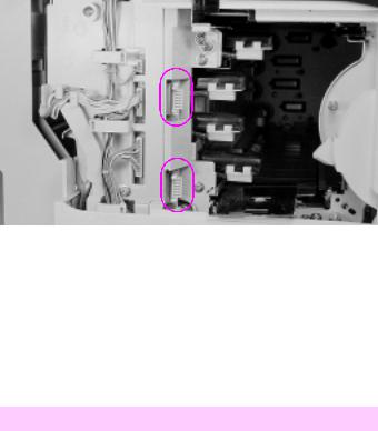
5The display should change from low to high (0 to 1) as the photosensor is activated. If it does not change, check that the PS8 connector on the highvoltage power supply (HVPS) is fully seated, as shown in the figure below. (The connectors are on the back of the HVPS.)
6Replace the photosensor.
EN |
Control panel messages 9 |

Photosensor PS8 connections on HVPS (HVPS inverted)
11.X Rear tray empty
•Check that the rear feed unit (RFU) is installed and that it has paper in it.
•Remove the RFU and check that the connector is not damaged.
•Remove and reseat the RFU if paper is present.
Note
Do not remove or install the RFU when the power is on. The printer only checks for the presence of the RFU when the printer is turned on.
10 Chapter 1 – Troubleshooting control panel messages |
EN |

12 Close top or side door
•The printer’s top or side door is open or the door sensor has failed.
– Close the top or side door or replace the door sensor. |
1 |
•One of the two interlock switches (MS2 or MS3) may be defective. If the following test proves that the switches are defective, replace the interlock switch assembly as shown in Chapter 6 of the printer service manual.
Note
Power cycle the printer and re-close both doors to confirm the message before troubleshooting.
Test the interlock switch
WARNING!
Do not inhibit the free movement of the interlock switch. If this mechanism is blocked, voltage may be present when the top cover is open.
1Open and close the top cover. If the message remains, open and close the side door.
2Open the side door and push the interlock mechanism with a flatblade screwdriver (see “Testing the interlock switches” on page 7-21 of the service manual), while running test 41 from Service Mode (see Chapter 3).
3If the message persists, remove the top cover and check that the switch linkage is not bent.
4Check that the switch connectors are in good repair. Toggle the switches by pressing down on the metal tab over the switches.
5If the linkage is not damaged, remove the switch assembly and test it with an ohmmeter.
6Replace the assembly if it is defective.
EN |
Control panel messages 11 |

13.1 Clear drum winding jam
Note
The locations of all sensors are identified on page 139.
•Paper is detected in the out of limit area of the print drum. The drum-winding jam sensor indicates that paper is beginning to wrap around the print drum.
–Turn the paper stack over end-to-end.
–Check that the paper meets HP paper specifications for the printer.
–Check that media is not being re-fed into the printer.
–Check that the drum-wrap sensor is not blocked by opening the side door and checking for paper wrapped around the drum.
•If no paper is seen, calibrate the drum-winding jam sensor by entering into Service Mode (see “Accessing Service Mode” on page 87“) and running test 47.
•See “Troubleshooting paper feed problems” on page 68.
13.2 Clear output jam
Note
The locations of all sensors are identified on page 139.
•Print media is jammed in the exit assembly because it failed to clear the exit sensor (PS1) in the allotted time.
–Check that the sensor flag moves freely and that the sensor is free of paper dust.
–Check that media is not in the sensor when the printer is turned on.
–Test the operation of the sensors by entering Service Mode (see “Accessing Service Mode” on page 87“) and running test 22.
•See “Troubleshooting paper feed problems” on page 68.
12 Chapter 1 – Troubleshooting control panel messages |
EN |

13.4 Clear front tray input jam
Note |
1 |
The locations of all sensors are identified on page 139. |
•The printer detects a paper jam in the front tray area.
–Clear the front tray area.
•The paper failed to arrive at PS7 within the allotted time after SL1 (the paper feed solenoid) was engaged.
–Inspect the input and registration area for media. Transparencies can be especially difficult to see.
–Test the operation of the sensors by entering Service Mode (see “Accessing Service Mode” on page 87“) and running test 20.
•See “Troubleshooting paper feed problems” on page 68.
13.5 Clear fuser jam (CLJ)
13.5Clear paper jam (CLJ5)
•Paper did not arrive at PS1 (exit sensor) in the allotted time. (See the diagram on page 141 for the location of PS1.)
– Check that PS1 is free throughout its entire range of travel and that media is not at the sensor when the printer is turned on.
– Check for paper dust in the sensor.
– Check to see if media has cleared the registration plate. If media is present, check the operation of the registration plate solenoid by running test 25 from the status and test section of the printer service manual.
•Check to see if the transfer assembly is installed correctly.
•Test the interlock switch. (For instructions, see the section called “To test the interlock switch” under error message 12 on page 11.)
•See “Troubleshooting paper feed problems” on page 68.
EN |
Control panel messages 13 |

13.6Clear rear tray input jam
•The printer detects paper in the rear input area.
– Clear the RFU.
•The sensor (PS4) did not activate within the allotted time after M7 started. (See the diagram on page 142 for the location of PS4.)
– Repair the sensor.
– Check that PS4 is not blocked.
•Sensor PS4, the RFU paper sensor, failed to detect paper media within the allotted time.
– Check that the sensor is not stuck.
– Check if media has been picked from the tray.
•Verify that the RFU is properly adjusted for the loaded media.
•See “Troubleshooting paper feed problems” on page 68.
13.7Clear rear tray paper jam
Note
The locations of all sensors are identified on page 140.
•The printer detects a paper jam at the rear input area. This message indicates that the paper was picked, but did not arrive at the registration area (PS7), in the allotted time.
–Clear the jam and check the paper feed rollers.
–Check that sensor PS4 is not defective and that it is free throughout its travel.
•See “Troubleshooting paper feed problems” on page 68.
13.8Clear paper jam
•Paper is jammed in the paper registration area.
– Open the printer and remove the jammed paper.
•Paper may be on PS7 when the printer is turned on. (See the diagram on page 141 for the location of PS7.)
– Check that PS7 is free.
•See “Troubleshooting paper feed problems” on page 68.
14 Chapter 1 – Troubleshooting control panel messages |
EN |
13.8Internal paper jam during warm-up
•Media was detected in the printer during warm up.
– Open the top cover and clear any media found inside the printer. 1
–If no media is found in the printer, check all sensors by running the tests described under error messages 13.1, 13.2, 13.4, and 13.5.
•Verify that all paper path sensors are not blocked and that the detection flags are free throughout their travel.
•See “Troubleshooting paper feed problems” on page 68.
14.5 Replace collection box
16.5Replace collection box
•Remove the toner collection box from the OPC drum assembly and inspect the flexible diaphragm (in the top surface of the collection box).
– If the diaphragm has been pushed above the collection box surface by accumulated toner, the box is full. In this case, the collection box must be replaced. Do not attempt to push the diaphragm down to correct this condition.
•The excess toner collection box is monitored by PS3. (See the diagram on page 141 for the location of PS3.) Perform the sensor checks below to isolate the problem.
Toner collection box full sensor tests
1Power cycle the printer.
2Open the top cover and lower the print drum.
3Pull the toner collection box out of the drum assembly.
4Verify that the toner-full flag is moving freely (it should raise up as you are pulling the toner collection box out of the assembly and drop down once the collection box is removed).
5Check to see if the toner collection box is full. If the toner collection box is full, the diaphragm will be pushed out. If it is pushed out, then the collection box is full and needs to be replaced.
EN |
Control panel messages 15 |
CAUTION
Do not try to continue using the toner collection box by pushing the diaphragm down.
6Check that the PS3 sensor is fully seated, clean, and connected properly. (See the diagram on page 141 for the location of PS3.)
If these tests are not effective, perform the PS3 Service Mode test described below.
Note
If the collection box is overfilled, the printer may need a thorough cleaning. In addition, the excess toner auger (inside the print drum) may be compacted or broken. The print drum may have to be replaced.
PS3 Service Mode test
Note
The PS3 sensor flag is not accessible to toggle by hand. You must have an empty collection box to perform this test.
1Power cycle the printer and enter the Service Mode (see “Accessing Service Mode” in Chapter 3.)
2Select the status and test Mode of the Service menu.
3Enter the PS3 test address (55), and press [Enter].
4Install the empty collection box. If the display is high (1), the sensor is stuck or defective.
5If the display is low (0), pull out the collection box about an inch to make the sensor flag rise. If the display does not change from 0 to 1, the sensor flag is stuck or broken or the sensor (PS3) is dislodged or defective.
6Check connector CN904 on the toner sensor PCA (Color LaserJet only).
16 Chapter 1 – Troubleshooting control panel messages |
EN |

14.6Replace coating kit
•If this message does not clear when the coating pad kit is replaced,
the fusible link in the coating pad may not be contacting the leaf |
1 |
spring in the fusing assembly or a coating kit with a blown fuse has been installed.
– Reseat the coating pad.
Color LaserJet only
•If a new style fusing assembly with a purple handle has been installed, then the fusible-link contacts are not making proper electrical contact with the contact fusing spring assembly.
– Reseat the cleaning roller.
CAUTION
The printer should continue to print when returned online. The fuser and main drive may be damaged if the oil pad and cleaning roller are not replaced as soon as possible.
16.5Replace collection box
•See “14.5 Replace collection box.”
17.1Install developer
17.2Install developer
•The printer failed to detect either the black developer (for the 17.1 message) or the color developer (for the 17.2 message).
– If the developer is not installed, install it.
1Power cycle the printer.
2If the message persists, remove the suspected developer and inspect the blade connectors that insert into the toner sensor PCA. Check that they are clean and straight. Also check the toner sensor PCA connectors.
3Re-install the developer.
EN |
Control panel messages 17 |
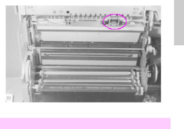
Toner sensor PCA connections (circled)
4Check all the connectors on the toner sensor PCA. Ensure that they are all fully seated.
5Check the wiring behind the power supply drawer for nicks or cuts that may cause the signal line to short to ground. Reseat the connectors if any are suspect.
6Replace the toner sensor PCA if necessary.
7If steps 1 through 6 do not resolve the problem, replace the developer.
17.4Install fuser
•The fuser is not installed, or the printer failed to detect the fuser.
1Power cycle the printer.
2If the message persists, remove and reseat the fuser.
3Check that the fuser connectors are not damaged (no bent or broken pins).
4Check that nothing prevents the fuser from fully seating into its plug.
5Check the connector (CN105) at the control PCA.
18 Chapter 1 – Troubleshooting control panel messages |
EN |

6Replace the fuser.
7Replace the control PCA if necessary.
|
1 |
|
17.6 Install collection box |
||
|
||
|
|
•The toner collection box or the print drum is not installed or is not detected. The switches that post this message are inside the print drum cartridge and cannot be tested directly.
1 Power cycle the printer to clear the message.
With the printer turned off and unplugged, inspect the print drum connector (see the figure under “17.8 Reinstall drum”). Ensure that the connections are not bent and that both the male and female ends are in good repair and clean.
2Ensure that nothing inhibits the print drum from fully seating into the connection.
3Check that CN101 on the control PCA and CN 254 on top of the developer bias supply are fully seated.
4Reseat the collection box and listen for an audible click.
5If the collection box does not click into place, the leaf spring inside the housing may be defective. Replace the print drum.
6Remove the drum and very carefully clean the inside of the sensor, using a cotton swab and isopropyl alcohol.
7Re-install the drum.
EN |
Control panel messages 19 |

17.7Remove drum cover
•The protective shipping cover for the print drum has not been removed.
– Remove the drum cover (see the printer service manual for instructions) or clear the drum wrap sensor.
•If the error persists, perform the status and test checks (see the printer service manual) to test the drum wrap sensor.
•If the error still persists, perform the drum reflectance calibration (Service Mode status and test address 47). Also see the procedures for the 66.1 Jam sensor service message.
17.8Reinstall drum
•This message indicates that the drum-winding sensor output is abnormal during printing (see 66.1 Jam sensor error message).
•A jam sensor could be broken or defective, or a connection could be loose.
1Remove the print drum and inspect both sides of the connector as shown in the “Print drum connector” figure below.
2Re-install the print drum. Check that nothing prevents the print drum from being fully seated into the printer.
Note
If the drum assembly is for a Color LaserJet 5/5M (the assembly will be purple-coded), you will need to make sure the corona cleaning lever on the drum is fully seated to the right.
3Power cycle the printer.
4Run test 47 in Service Mode (see Chapter 3 for information on accessing Service Mode).
5Replace the drum cartridge assembly.
20 Chapter 1 – Troubleshooting control panel messages |
EN |
1
Print drum connector (circled).
17.9Reinstall fuser
•The fuser did not warm up correctly.
– Reseat the fuser.
•The fuser connection is not stable.
WARNING!
The fuser is HOT. Turn off the printer to allow the fuser to cool for at least 30 minutes before beginning this procedure.
–Power cycle the printer to clear the message.
•If the message persists:
–Remove the fuser. Check that all the connectors are straight and clean.
–Reseat the fuser, being certain that all the connectors make contact.
•If the message persists, replace the fuser.
EN |
Control panel messages 21 |

18.1Clean transfer corona wire
•The paper-charging brush or the bias roller in the transfer assembly is arcing.
– Power cycle the printer.
– Clean the transfer corona wire (see Chapter 2, “Cleaning and maintenance”).
– Check connector CN701 on the control PCA and connector CN702 on the HVPS.
– Replace the transfer assembly and try another test print.
– Replace the HVPS.
18.2Reinstall drum
•The printer sensed a high-voltage leak in the print drum neutralizing corona.
– Power cycle the printer to clear this error.
– Remove and reinstall the print drum. Try a test print.
– Check connector CN731 on the control PCA and connector CN730 on the HVPS.
– Check the neutralizing corona contact for damage or contamination. (see the “Neutralizing corona contacts” figure below.)
– Replace the print drum.
– Replace the HVPS.
•The neutralizing corona may have arced.
– Clean the printer.
22 Chapter 1 – Troubleshooting control panel messages |
EN |

1
Neutralizing corona contacts (circled)
18.3Reinsert developers
•The printer detected a high-voltage leak in the developer bias power supply. (Although this is a developer bias fault, the print drum is often the root cause of this failure.)
•The developer is not turning.
1Remove each developer and check their pin contacts.
2Check that each of the high voltage contacts on the developer bias assembly is clean and located correctly.
3Print several self-tests and look for repetitive defects. Replace the print drum if repetitive defects appear.
4Remove the print drum and check its surface for any bright metallic spots, dents, or defects that may indicate an arcing point (anywhere in the green area). Replace the print drum if any defects are found.
5Check CN601 on the developer bias supply and CN600 on the control PCA.
6Try a test print.
EN |
Control panel messages 23 |

•If the message persists, replace the print drum followed by the color developer and the black developer if necessary.
7 Replace the developer bias power supply.
18.4Clean transfer corona
•There is a high-voltage leak in the transfer belt, print drum, or HVPS.
– Power cycle the printer.
Note
If the problem will not repeat dependably, print transparencies in color. Transparencies print at a slower speed with a higher transfer current.
•Clean the transfer corona (see Chapter 2, “Cleaning and maintenance”).
•Check that the print drum contacts are clean.
•Remove the transfer belt assembly and print a test page.
•If a 13.x Paper jam message appears when printing without the transfer assembly installed, the high-voltage leak is associated with the transfer assembly.
–Check the transfer assembly contacts for proper alignment, corrosion, etc. before replacing them.
•If the error persists, reseat the print drum. Then replace the print drum followed by the HVPS if necessary.
24 Chapter 1 – Troubleshooting control panel messages |
EN |
 Loading...