


 Loading...
Designjet T920, T1500 ePrinter Series and
T2500, T3500 eMultifunction Series
Service Manual
1 |
Legal notices |
© 2014 Hewlett-Packard Development |
This document contains proprietary |
Company, L.P. |
information that is protected by copyright. All |
|
rights are reserved. No part of this document |
|
may be photocopied, reproduced, or translated |
|
to another language without the prior written |
|
consent of Hewlett-Packard Company. |
Warranty
The information contained in this document is subject to change without notice.
Hewlett-Packard makes no warranty of any kind with regard to this material, including, but not limited to, the implied warranties of merchantability and fitness for a particular purpose.
Hewlett-Packard shall not be liable for errors contained herein or for incidental or consequential damages in connection with the furnishing, performance, or use of this material.
Safety
The Warning symbol calls attention to a procedure, practice, or the like, which, if not correctly performed or adhered to, could result in personal injury. Do not proceed beyond a Warning symbol until the indicated conditions are fully understood and met.
The Caution symbol calls attention to an operating procedure, practice, or the like, which, if not correctly performed or adhered to, could result in damage to or destruction of part or all of the printer. Do not proceed beyond a Caution symbol until the indicated conditions are fully understood and met.

Table of contents
1 Printer fundamentals .................................................................................................................................... |
1 |
Introduction ........................................................................................................................................................... |
2 |
Theory of operation ............................................................................................................................................... |
5 |
2 Troubleshooting .......................................................................................................................................... |
32 |
The front panel .................................................................................................................................................... |
32 |
Service keys combination .................................................................................................................................... |
35 |
Troubleshooting tree (T920 and T1500 only) .................................................................................................... |
36 |
Product Troubleshooting trees (T2500 and T3500 only) ................................................................................... |
38 |
Scanner Troubleshooting Tree ............................................................................................................................ |
39 |
Scanner CIS Troubleshooting .............................................................................................................................. |
40 |
Paper handling problems .................................................................................................................................... |
41 |
Ink supply problems ............................................................................................................................................ |
52 |
Print-quality problems ........................................................................................................................................ |
61 |
Connectivity problems ......................................................................................................................................... |
76 |
Scanning Problems .............................................................................................................................................. |
81 |
Firmware upgrades .............................................................................................................................................. |
83 |
3 System error codes ...................................................................................................................................... |
84 |
Introduction ......................................................................................................................................................... |
85 |
What to do if the front panel fails to initialize .................................................................................................... |
87 |
System error codes in brief ................................................................................................................................. |
89 |
System error codes in full ................................................................................................................................... |
92 |
Appendix A: How to troubleshoot system error 79:04 and 79.2:04 ................................................................ |
118 |
Appendix B: Updating firmware in boot mode .................................................................................................. |
129 |
Appendix C: Obtaining the diagnostics package ............................................................................................... |
130 |
4 Diagnostics, Service Utilities and Calibrations ............................................................................................. |
132 |
Introduction ....................................................................................................................................................... |
133 |
Diagnostic Tests and Utilities ............................................................................................................................ |
134 |
Service Utilities .................................................................................................................................................. |
151 |
Service Calibrations ........................................................................................................................................... |
176 |
ENWW |
v |
5 Parts and diagrams .................................................................................................................................... |
184 |
Introduction ....................................................................................................................................................... |
184 |
Printer support .................................................................................................................................................. |
185 |
Center and Roll covers ....................................................................................................................................... |
186 |
Rear covers ........................................................................................................................................................ |
187 |
Cover Front Panel Side ...................................................................................................................................... |
188 |
Cover SVS Side ................................................................................................................................................... |
189 |
Center Assemblies ............................................................................................................................................. |
190 |
Front Panel Side Assemblies ............................................................................................................................. |
191 |
SVS Side Assemblies .......................................................................................................................................... |
192 |
Scan Axis Assemblies ........................................................................................................................................ |
193 |
Paper Path Assemblies (Front) ......................................................................................................................... |
194 |
Paper Path Assemblies (Center) ........................................................................................................................ |
195 |
Stacker Parts (Rear) .......................................................................................................................................... |
197 |
Stacker Parts (Front) ......................................................................................................................................... |
198 |
Carriage Assembly ............................................................................................................................................. |
199 |
Electrical Parts ................................................................................................................................................... |
200 |
Miscellaneous Parts .......................................................................................................................................... |
202 |
CIS Unit Construction ......................................................................................................................................... |
203 |
Scanner Control Unit ......................................................................................................................................... |
204 |
6 Removal and installation ........................................................................................................................... |
207 |
Parts list; all models .......................................................................................................................................... |
208 |
Parts list; HP Designjet T2500 and T3500 eMultifunction Series only ............................................................ |
210 |
Parts list; HP Designjet T3500 eMultifunction Series only ............................................................................... |
211 |
Introduction ....................................................................................................................................................... |
212 |
Customer Self Repair parts ............................................................................................................................... |
214 |
Service Calibration Guide to Removal and Installation .................................................................................... |
215 |
Main cover (front panel side) ............................................................................................................................ |
218 |
Main cover (service station side) ....................................................................................................................... |
220 |
Center cover (T920 only) ................................................................................................................................... |
222 |
Converger Assembly .......................................................................................................................................... |
224 |
Cleanout ............................................................................................................................................................. |
225 |
Output platen .................................................................................................................................................... |
227 |
Fixed tray cover (Front Panel side) ................................................................................................................... |
228 |
Fixed tray cover (service station side) .............................................................................................................. |
229 |
Arch sidewall cover (front panel side) .............................................................................................................. |
230 |
Arch sidewall cover (service station side) ......................................................................................................... |
231 |
Rear cover .......................................................................................................................................................... |
232 |
Window Sensor .................................................................................................................................................. |
233 |
Open the E-Box .................................................................................................................................................. |
235 |
E-Box fan ........................................................................................................................................................... |
238 |
Jester PCA .......................................................................................................................................................... |
240 |
Power supply unit .............................................................................................................................................. |
241 |
vi |
ENWW |
Hard disk drive ................................................................................................................................................... |
243 |
Engine PCA ......................................................................................................................................................... |
244 |
Formatter PCA ................................................................................................................................................... |
245 |
Front panel ........................................................................................................................................................ |
248 |
Carriage .............................................................................................................................................................. |
251 |
Line Sensor ........................................................................................................................................................ |
255 |
Carriage PCA ...................................................................................................................................................... |
256 |
Rail Oiler Kit ....................................................................................................................................................... |
258 |
PRS Actuator ...................................................................................................................................................... |
259 |
Belt ..................................................................................................................................................................... |
261 |
Encoder Strip ..................................................................................................................................................... |
262 |
Scan Axis Motor ................................................................................................................................................. |
264 |
Drop Detector .................................................................................................................................................... |
267 |
Service Station with Drop Detector ................................................................................................................... |
268 |
Primer Assembly ............................................................................................................................................... |
272 |
ISS (Ink Supply Statino) Front Panel Side ......................................................................................................... |
275 |
ISS SVS Side ....................................................................................................................................................... |
278 |
Ink Tubes and Trailing Cable ............................................................................................................................. |
282 |
Media Sensor ..................................................................................................................................................... |
285 |
Bottom Rewinder Support ................................................................................................................................ |
287 |
Top Rewinder Support ....................................................................................................................................... |
289 |
Top Tip Support ................................................................................................................................................. |
291 |
Bottom Tip Support ........................................................................................................................................... |
292 |
Vertical Media Guide .......................................................................................................................................... |
294 |
Center Support .................................................................................................................................................. |
296 |
Full Bleed ........................................................................................................................................................... |
297 |
Auto Pinch Lifter ................................................................................................................................................ |
298 |
Pinch Wheel Assembly ...................................................................................................................................... |
303 |
Motor Media Advance Transmission with Encoder ........................................................................................... |
305 |
Starwheel Motor ................................................................................................................................................ |
313 |
Starwheel Support ............................................................................................................................................. |
318 |
Second Starwheel Rail ....................................................................................................................................... |
320 |
Overdrive ........................................................................................................................................................... |
322 |
Cutter Platten .................................................................................................................................................... |
324 |
Sensor Valves .................................................................................................................................................... |
326 |
Valves Motor ...................................................................................................................................................... |
329 |
Stacker ............................................................................................................................................................... |
330 |
Stacker adaptor for MFP ................................................................................................................................... |
332 |
Stacker Pinches ................................................................................................................................................. |
336 |
Stacker Hand Off ............................................................................................................................................... |
337 |
Stacker Hand Off Assy Service Kit (CR357-67041) ........................................................................................... |
338 |
OPTO Sensor ...................................................................................................................................................... |
341 |
REDI sensor ........................................................................................................................................................ |
343 |
OVD Transmission with Motor ........................................................................................................................... |
344 |
ENWW |
vii |
Ramps Motor ..................................................................................................................................................... |
346 |
Stacker Arm Sensor ........................................................................................................................................... |
348 |
Bump Cutter Actuator ........................................................................................................................................ |
350 |
How to release Service Station Caps ................................................................................................................. |
351 |
How to manually move Valves .......................................................................................................................... |
352 |
How to manually move Stacker Ramps ............................................................................................................ |
353 |
Scanner Controller Unit (SUP) ........................................................................................................................... |
354 |
CIS Tiles .............................................................................................................................................................. |
355 |
CIS Modules ........................................................................................................................................................ |
356 |
CIS FFC Cables .................................................................................................................................................... |
357 |
CIS Glass ............................................................................................................................................................. |
358 |
Stepper Motor Assembly (taco sensor, and belt) ............................................................................................. |
359 |
Stepper Motor Assembly (cable) ....................................................................................................................... |
361 |
Paper and Lid Sensors ....................................................................................................................................... |
362 |
Paper and Lid Sensor Cable ............................................................................................................................... |
364 |
USB & Awake / Power Cable .............................................................................................................................. |
365 |
CIS Bridge Damper ............................................................................................................................................. |
367 |
CIS Scanner Latch .............................................................................................................................................. |
369 |
Pressure Rollers ................................................................................................................................................ |
370 |
Front panel side scanner cover ......................................................................................................................... |
371 |
Service station side scanner cover .................................................................................................................... |
372 |
Rear scanner cover ............................................................................................................................................ |
373 |
Bumper bracket ................................................................................................................................................. |
374 |
Deflector hinge .................................................................................................................................................. |
375 |
Lift assembly ..................................................................................................................................................... |
376 |
Scanner front beam bumper assembly ............................................................................................................ |
377 |
Scanner latch hook assembly ........................................................................................................................... |
378 |
Top scanner cover ............................................................................................................................................. |
379 |
Batch scanning piece ......................................................................................................................................... |
380 |
7 Maintenance ............................................................................................................................................. |
381 |
Preventive Maintenance .................................................................................................................................... |
382 |
Preventive Maintenance Kits ............................................................................................................................. |
388 |
8 Customer Self Repair Flyers ........................................................................................................................ |
389 |
viii |
ENWW |

1Printer fundamentals
●Introduction
●Theory of operation
ENWW |
1 |

Introduction
This service manual contains information necessary to test, maintain, and service the following:
●HP Designjet T920 ePrinter
●HP Designjet T920 PostScript ePrinter
●HP Designjet T1500 ePrinter
●HP Designjet T1500 PostScript ePrinter
●HP Designjet T2500 eMultifunction
●HP Designjet T2500 PostScript eMultifunction
●HP Designjet T3500 Production eMultifunction
●HP Designjet T3500 Production PostScript eMultifunction For information about using these printers, see the user's guide.
Features overview
There are 6 versions of the HP Designjet T920-T1500–T2500–T3500 series:
●CR354A HP Designjet T920 36-in ePrinter
●CR355A/B HP Designjet T920 36-in PostScript ePrinter
●CR356A HP Designjet T1500 36-in ePrinter
●CR357A/B HP Designjet T1500 36-in PostScript
●CR358A HP Designjet T2500 eMultifunction
●CR358A/B HP Designjet T2500 PostScript eMultifunction
●B9E24A/B HP Designjet T3500 Production eMFP
 NOTE: As of August 2013 there are no plans for an upgrade to enable PostScript features from nonPostScript capabilities.
The different sku features are:
Feature |
CR354A HP |
CR355A/B HP |
CR356A HP |
CR357A/B HP |
CR358A HP |
B9E24A/B HP |
|
Designjet T920 |
Designjet T920 |
Designjet T1500 |
Designjet T1500 |
Designjet T2500 |
Designjet T3500 |
|
36-in ePrinter |
36-in PostScript |
36-in ePrinter |
36-in PostScript |
eMultifunction |
Production |
|
|
ePrinter |
|
|
and CR358A/B |
eMFP |
|
|
|
|
|
HP Designjet |
|
|
|
|
|
|
T2500 |
|
|
|
|
|
|
PostScript |
|
|
|
|
|
|
eMultifunction |
|
|
|
|
|
|
|
|
Paper source |
One 36-in roll, and single sheets |
Two 36-in rolls, and single sheets |
|
|
||
|
|
|
|
|
|
|
Paper output |
Stacker, accepting up to 50 A1 plain-paper sheets, and basket |
|
|
|||
|
|
|
|
|
|
|
Connectivity |
Gigabit Ethernet LAN (1000 base T) |
|
|
|
|
|
|
One USB HS host connector in the front panel, for USB flash drives |
|
|
|||
|
IPv4, IPv6, IPSec, TCP9100, LPR, DHCP, AutoIP/Zeroconf, Bonjour, SNMP/v3, Airprint |
|
||||
|
|
|
|
|||
Web services |
Automatic firmware upgrade, HP Designjet ePrint & Share, printing by email |
|
|
|||
|
|
|
|
|
|
|
2 Chapter 1 Printer fundamentals |
ENWW |
Feature |
CR354A HP |
|
CR355A/B HP |
|
CR356A HP |
CR357A/B HP |
CR358A HP |
B9E24A/B HP |
|
|
Designjet T920 |
|
Designjet T920 |
|
Designjet T1500 |
Designjet T1500 |
Designjet T2500 |
Designjet T3500 |
|
|
36-in ePrinter |
|
36-in PostScript |
|
36-in ePrinter |
36-in PostScript |
eMultifunction |
Production |
|
|
|
|
|
ePrinter |
|
|
|
and CR358A/B |
eMFP |
|
|
|
|
|
|
|
|
HP Designjet |
|
|
|
|
|
|
|
|
|
T2500 |
|
|
|
|
|
|
|
|
|
PostScript |
|
|
|
|
|
|
|
|
|
eMultifunction |
|
|
|
|
|
|
|
|
|||
Speed |
Line-drawing, fast, plain paper: 21.6 s mono or color on A1&D |
|
|
||||||
|
Color image, normal, plain paper: 69 s on A1&D |
|
|
|
|||||
|
Color image, best, glossy paper: 246 s on A1&D |
|
|
|
|||||
|
|
|
|
||||||
Resolution |
Up to 2400×1200 optimized dpi from 1200×1200 input ppi |
|
|
||||||
|
|
||||||||
Memory |
1.5GB RAM (2.5GB RAM T3500);1GB in Formatter and 512MB in Engine PCA), 320 GB hard disk, 32 GB Dedicated |
||||||||
|
file-processing memory, 32GB (T920 series), 64 GB (T1500 series), and 128 GB (T2500 and T3500 series), Virtual |
||||||||
|
Memory |
|
|
|
|
|
|
||
|
|
|
|
|
|
||||
Supplies |
Off-axis ink cartridges: |
|
|
|
|
||||
|
● |
Introductory supplies: 69 ml (40 ml T3500) matte black, photo black, gray, cyan, magenta, yellow |
|||||||
|
● |
Replacement supplies: 69 ml / 300 ml (130 ml T3500) matte black, for other colors 40 ml / 130 ml; photo |
|||||||
|
|
black, gray, cyan, magenta, yellow |
|
|
|
||||
|
● |
Can be replaced by the customer |
|
|
|
|
|||
|
One printhead for all colors: |
|
|
|
|
||||
|
● |
9/8-in length |
|
|
|
|
|
|
|
|
● |
Drop size: 9 pl matte black / 6 pl other inks |
|
|
|
||||
|
● |
Can be replaced by the customer |
|
|
|
|
|||
|
|
|
|
|
|
|
|
|
|
Hardware |
|
|
|
|
|
X |
X |
X |
X |
differentiation: |
|
|
|
|
|
|
|
|
|
|
|
|
|
|
|
|
|
|
|
Second roll |
|
|
|
|
|
X |
X |
X |
X |
|
|
|
|
|
|
|
|
|
|
Borderless |
|
|
|
|
|
X |
X |
X |
X |
printing on roll |
|
|
|
|
|
|
|
|
|
photo media |
|
|
|
|
|
|
|
|
|
|
|
|
|
|
|
|
|
|
|
Other |
|
|
|
|
|
X |
X |
X |
X |
differentiations |
|
|
|
|
|
|
|
|
|
: |
|
|
|
|
|
|
|
|
|
|
|
|
|
|
|
|
|
|
|
Languages |
HP-GL/2, HP- |
|
Adobe |
|
HP-GL/2, HP- |
Adobe PostScript 3, Adobe PDF 1.7ext3 HP-GL/2, HP- |
|||
supported |
RTL, TIFF, JPEG, |
|
PostScript 3, |
|
RTL, TIFF, JPEG, |
RTL, TIFF, JPEG, CALS G4, HP PCL 3 GUI, URF |
|||
|
CALS G4, HP PCL |
|
Adobe PDF |
|
CALS G4, HP PCL |
|
|
|
|
|
3 GUI, URF |
|
1.7ext3 HP- |
|
3 GUI, URF |
|
|
|
|
|
|
|
|
GL/2, HP-RTL, |
|
|
|
|
|
|
|
|
|
TIFF, JPEG, CALS |
|
|
|
|
|
|
|
|
|
G4, HP PCL 3 |
|
|
|
|
|
|
|
|
|
GUI, URF |
|
|
|
|
|
|
|
|
|
|
|
|
|
|
|
Virtual Memory |
32 |
|
|
32 |
|
64 |
64 |
128 |
128 |
[GB] |
|
|
|
|
|
|
|
|
|
|
|
|
|
|
|
|
|
|
|
1 job in queue |
X |
|
|
|
|
|
|
|
|
(last job reprint) |
|
|
|
|
|
|
|
|
|
|
|
|
|
|
|
|
|
|
|
Job queues |
|
|
|
X |
|
X |
X |
X |
X |
|
|
|
|
|
|
|
|
|
|
Job preview |
|
|
|
X |
|
X |
X |
X |
X |
from queue |
|
|
|
|
|
|
|
|
|
|
|
|
|
|
|
|
|
|
|
ENWW |
Introduction 3 |
Feature |
CR354A HP |
CR355A/B HP |
CR356A HP |
CR357A/B HP |
CR358A HP |
B9E24A/B HP |
|
Designjet T920 |
Designjet T920 |
Designjet T1500 |
Designjet T1500 |
Designjet T2500 |
Designjet T3500 |
|
36-in ePrinter |
36-in PostScript |
36-in ePrinter |
36-in PostScript |
eMultifunction |
Production |
|
|
ePrinter |
|
|
and CR358A/B |
eMFP |
|
|
|
|
|
HP Designjet |
|
|
|
|
|
|
T2500 |
|
|
|
|
|
|
PostScript |
|
|
|
|
|
|
eMultifunction |
|
|
|
|
|
|
|
|
Crop marks and |
|
|
X |
X |
X |
X |
nesting |
|
|
|
|
|
|
|
|
|
|
|
|
|
EWS job |
|
|
X |
X |
X |
X |
submmital |
|
|
|
|
|
|
|
|
|
|
|
|
|
Job on-hold for |
|
X |
X |
X |
X |
X |
media |
|
|
|
|
|
|
(mummify) |
|
|
|
|
|
|
|
|
|
|
|
|
|
Auto rotate, |
X |
X |
X |
X |
X |
X |
automatic blank |
|
|
|
|
|
|
area removal |
|
|
|
|
|
|
|
|
|
|
|
|
|
Accounting in |
|
|
X |
X |
X |
X |
EWS |
|
|
|
|
|
|
|
|
|
|
|
|
|
Readership
The procedures described in this service manual are to be performed by HP Certified service personnel only.
Part numbers
Part numbers for printer service parts are located in Parts and diagrams on page 184.
Warning labels
Electric shock hazard
Hazardous voltage inside the printer (built-in power supply) could result in death or serious personal injury. See the installation instructions before connecting power. Ensure that the input voltage is within the printer's rated voltage range. Use only earthed mains outlets and the power cords supplied by HP with the printer. There are no operator-serviceable parts inside the printer. Refer servicing to qualified service personnel. Disconnect the power cord before servicing. Voltage is still present in the built-in power supply after the main switch is turned off.
Double pole/neutral fusing
Electric shock hazard. The built-in power supply incorporates a fuse on each conductor, therefore the printer could be energized even when one fuse has blown. There are no operator-replaceable fuses inside. Refer servicing to qualified service personnel. Disconnect the power cord before servicing.
4 Chapter 1 Printer fundamentals |
ENWW |
Theory of operation
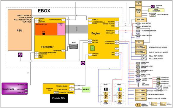
Schematics
Electronics are based on 3 main components:
●E-box - contains the power supply and all the PCAs (driving the printer), plus the Ethernet port.
●Carriage PCA - drives the printhead.
●Front Panel - user interface and USB port.
The following diagram describes the connections between components and electronic boards and the data line type for T920, T1500 and T2500.
Block Diagram
(HP Designjet T3500 eMultifunction Series only)
ENWW |
Theory of operation 5 |
6 Chapter 1 Printer fundamentals |
ENWW |
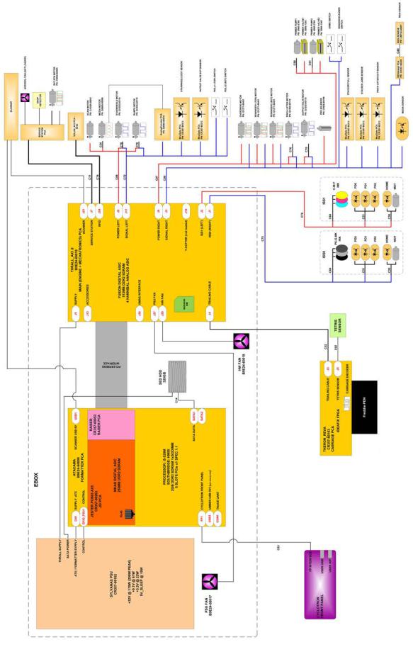
Block Diagram
(HP Designjet T2500 and T3500 eMultifunction Series only)
Wiring Diagram
(HP Designjet T2500 and T3500 eMultifunction Series only)
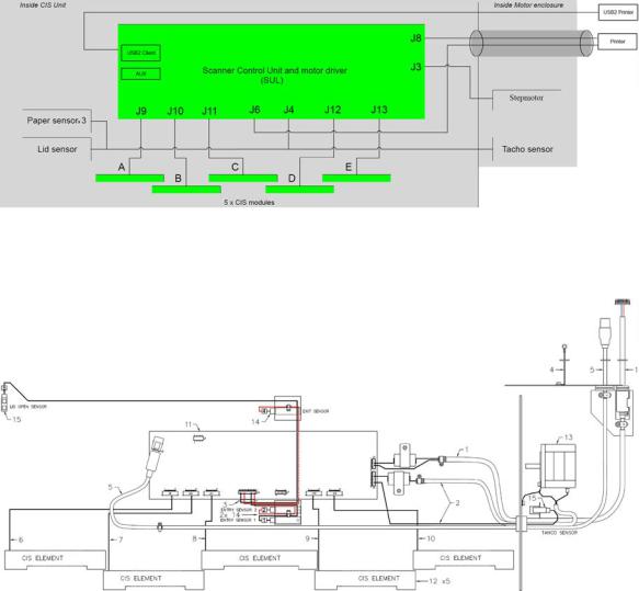
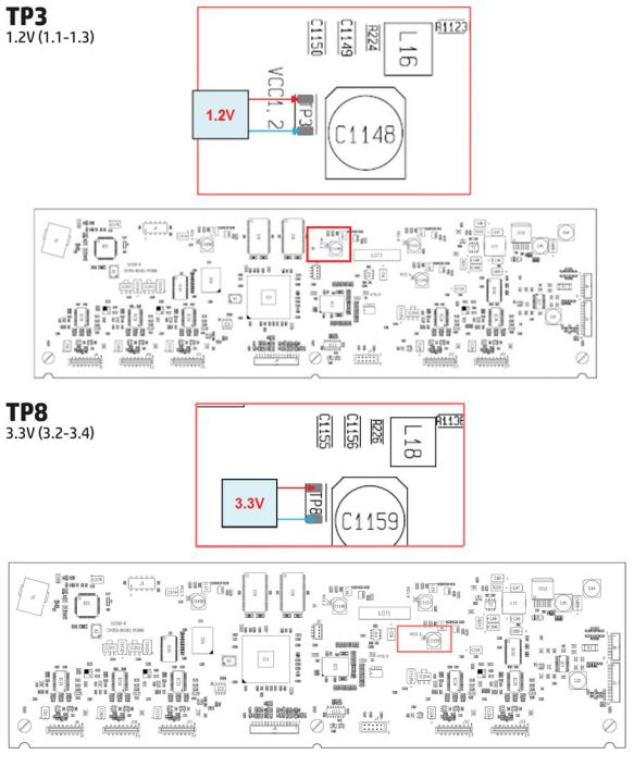
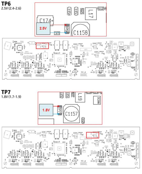
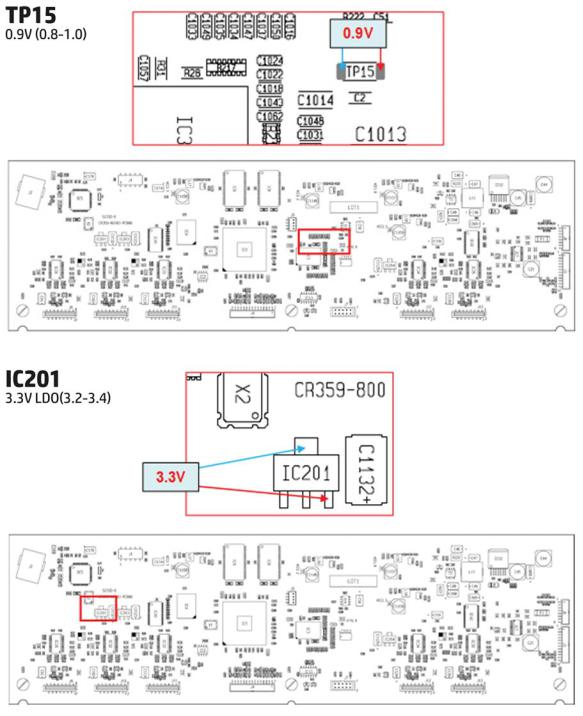
Scanner Controller Board Layout (SULG)
(HP Designjet T2500 and T3500 eMultifunction Series only)
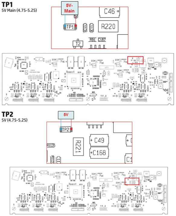
|
Voltage |
Min limit |
Max limit |
|
|
|
|
TP1 |
5V-Main (Always on when there |
4.75 |
5.25 |
|
is power to the board) |
|
|
|
|
|
|
TP2 |
5V |
4.75 |
5.25 |
|
|
|
|
TP3 |
1.2V |
1.1 |
1.3 |
|
|
|
|
TP8 |
3.3V |
3.2 |
3.4 |
|
|
|
|
TP6 |
2.5V |
2.4 |
2.6 |
|
|
|
|
TP7 |
1.8V |
1.7 |
1.9 |
|
|
|
|
TP15 |
0.9V |
0.8 |
1.0 |
|
|
|
|
IC201 |
3.3VLDO |
3.1 |
3.5 |
|
|
|
|
ENWW |
Theory of operation 7 |
|
Voltage |
Min limit |
Max limit |
|
|
|
|
IC203 |
3.3VLDO |
3.1 |
3.5 |
|
|
|
|
IC204 |
3.3VLDO |
3.1 |
3.5 |
|
|
|
|
8 Chapter 1 Printer fundamentals |
ENWW |
ENWW |
Theory of operation 9 |
10 Chapter 1 Printer fundamentals |
ENWW |
ENWW |
Theory of operation 11 |
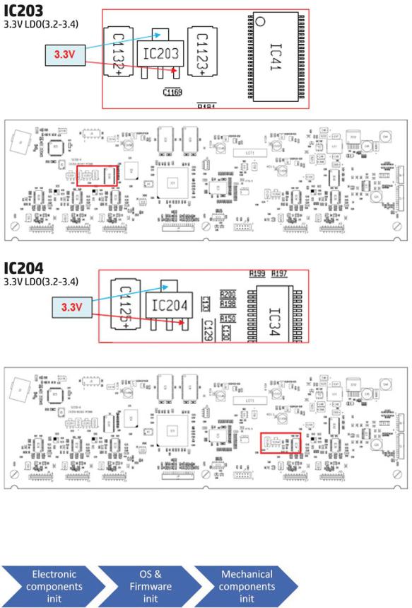
Printer Initialization
There are 3 main blocks to be initialized before the printer can be operated:
Electronic components init
1.The front panel shows a white background and blue HP logo.
12 Chapter 1 Printer fundamentals |
ENWW |

2.The upper LED in the formatter is ON, indicating that the formatter has been initialized.
3.The middle LED in the formatter blinks, indicating that the HDD has been initialized.
 NOTE: Steps 2&3 are the same when waking from Sleep Mode except the 3 LEDs are not on but; ON- Blinking-OFF
OS & Firmware init
1.The OS is loaded into RAM. The Front Panel blinks for a second.
2.If boot up is after a bad power-off, the boot sequence automatically runs a file system check. a. The Front Panel shows the FSCK, text.
b.First, FSCK runs on the root partition.
c.If FSCK is successful, the OS boots up from the root partition and runs FSCK on the data partition.
3.After FSCK, the OS finishes booting from the HDD.
4.The home button lights up to allow stopping the boot sequence, and entry to the diagnostics menu, see Diagnostics, Service Utilities and Calibrations on page 132.
Mechanical components init
1.The Front Panel shows a black background with a blue circle in the middle. The “Initializing” message appears. A progress bar shows the percentage of subsystems that have been initialized.
2.The printer moves the carriage from side to side to validate its position within the scan axis. The printer initializes the service station, moving the caps from bumper to bumper.
3.The pinches move down into position.
4.T2500 and T3500 only: The printer will initialize the Scanner and start checking it.
5.The carriage and service station move to the home position
6.The printer checks the status of supplies and the printhead, and then initializes the Ink Supply Stations.
ENWW |
Theory of operation 13 |
7.Servicing routines are launched. The routines refresh the printhead depending on the time that the printer has been off. The Front Panel shows “Preparing Print System”.
8.The paper path subsystems are initialized by exercising the ramps and rewinder, checking if there is media present over the Media Sensor.
9.At the end of the process, the home screen appears in the Front Panel.
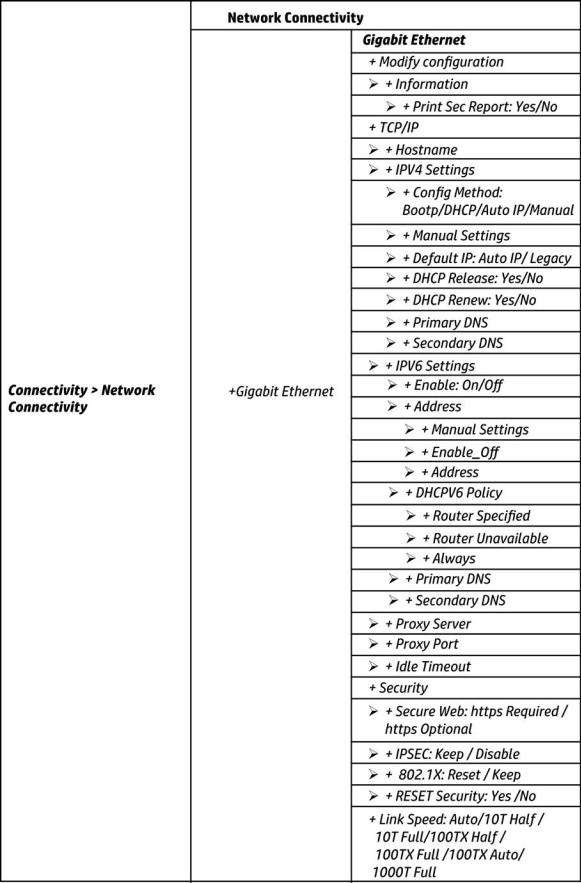
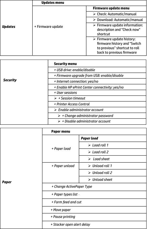
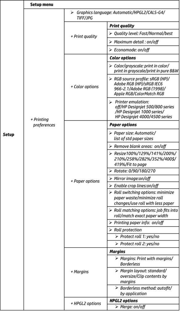
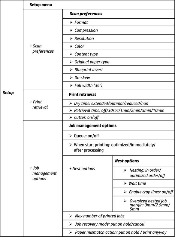
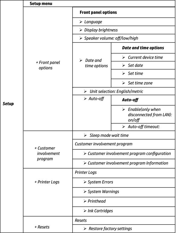
Front Panel Menu Map
The following tables show the front panel menu layout.
14 Chapter 1 Printer fundamentals |
ENWW |

ENWW |
Theory of operation 15 |
16 Chapter 1 Printer fundamentals |
ENWW |

ENWW |
Theory of operation 17 |
18 Chapter 1 Printer fundamentals |
ENWW |

ENWW |
Theory of operation 19 |

20 Chapter 1 Printer fundamentals |
ENWW |
ENWW |
Theory of operation 21 |
22 Chapter 1 Printer fundamentals |
ENWW |
ENWW |
Theory of operation 23 |
Loading...