


 Loading...
HP DesignJets 500, 510 and 800 Series Large-Format Printers
Service Manual

For HP Internal Use Only
©Copyright Hewlett-Packard Company 2000
This document contains proprietary information that is protected by copyright. All rights are reserved. No part of this document may be photocopied, reproduced, or translated to another language without the prior written consent of HewlettPackard Company.
First Edition, August 2000 Second Edition, November 2001 Third Edition, August 2008
Fourth Edition, January 2013
Warranty
The information contained in this document is subject to change without notice.
Hewlett-Packard makes no warranty of any kind with regard to this material, including, but not limited to, the implied warranties of merchantability and fitness for a particular purpose.
Hewlett-Packard shall not be liable for errors contained herein or for incidental or consequential damages in connection with the furnishing, performance, or use of this material.
WARNING
The procedures described in this manual are to be performed by HP-qualified service personnel only.
Electrical Shock Hazard
Serious shock hazard leading to death or injury may result if you do not take the following precautions:
-Ensure that the ac power outlet (mains) has a protective earth (ground) terminal.
-Disconnect the Printer from the power source prior to performing any maintenance.
-Prevent water or any other liquids from running onto electrical components or circuits, or through openings in the enclosure.
Electrostatic Discharge
Refer to the beginning of Chapter 8 of this manual, for precautions you should take to prevent damage to the Printer circuits from electrostatic discharge.
Safety Symbols
General definitions of safety symbols are given immediately after the table of contents.
WARNING
The Warning symbol calls attention to a procedure, practice, or the like, which, if not correctly performed or adhered to, could result in personal injury. Do not proceed beyond a Warning symbol until the indicated conditions are fully understood and met.
CAUTION
The Caution symbol calls attention to an operating procedure, practice, or the like, which, if not correctly performed or adhered to, could result in damage to or destruction of part or all of the product. Do not proceed beyond a Caution symbol until the indicated conditions are fully understood and met.
Technical Marketing,
Barcelona Division, Hewlett-Packard Espanola, S.A. Avda. Graells, 501
08190 Sant Cugat del Valles Spain
HP DesignJets 500, 510 and 800 Series Large-Format Printers
Service Manual

Using this Manual
Purpose
This Service Manual contains information necessary to test, calibrate and service:
HP DesignJet 500 Printer - 24” Model (P/N C7769B)
HP DesignJet 500 Printer - 42” Model (P/N C7770B)
HP DesignJet 500PS Printer - 24” Model (P/N C7769C)
HP DesignJet 500PS Printer - 42” Model (P/N C7770C)
HP DesignJet 500Plus – 24” Model (P/N C7769F)
HP DesignJet 500Plus – 42” Model (P/N C7770F)
HP DesignJet 500Mono – 24” Model (P/N C7769E)
HP DesignJet 500Mono – 42” Model (P/N C7770E)
HP Designjet 510 – 24” Model (P/N CH336A)
HP Designjet 510 – 42” Model (P/N CH337A)
HP Designjet 510ps – 24” Model (P/N CJ996A)
HP Designjet 510ps – 42” Model (P/N CJ997A)
HP DesignJet 800 Printer - 24” Model (P/N C7779B)
HP DesignJet 800 Printer - 42” Model (P/N C7780B)
HP DesignJet 800PS Printer - 24” Model (P/N C7779C)
HP DesignJet 800PS Printer - 42” Model (P/N C7780C)
For information about using these printers, refer to the corresponding User and Quick Reference Guides.
Readership
The procedures described in this Service Manual are to be performed by HP Certified Service Personnel only.
Part Numbers
Part Numbers for Printer options, accessories and service parts are
2 |
HP DesignJets 500, 510 and 800 Series Printers Service Manual |

located in Chapter 7.
Conventions
A small arrow is used to indicate other parts of the Service Manual where you can find information related to the topic you are consulting.
HP DesignJets 500, 510 and 800 Series Printers Service Manual |
3 |

Table of Contents
Table of Contents
Troubleshooting 1-1
Introduction 1-2
Troubleshooting System Error Codes 1-2 Solving Print Quality Problems 1-3 Cover Sensors are not Working 1-3
The Line Sensor has Problems Detecting Media 1-3 Troubleshooting Paper-Axis Shutdowns 1-4 Problems with the Vacuum Fan 1-5
Vacuum suction much lower at high altitudes 1-5
HP-GL/2 color differences in different HP DesignJet Printers 1-6 Banding at variable extreme environmental conditions 1-6
The Priming Procedure Fails 1-7
Using the Power Switch LED to Troubleshoot 1-10 Using the Boot-Up Sequence to Troubleshoot 1-12
Using the Formatter/Accessory Card LEDs to Troubleshoot 1-14
System Error Codes 2-1
Introduction 2-2
Continuable and Non-Continuable Error Codes 2-2
System Error Codes - Explanation 2-2
Error Log Utility 2-5
Accessing the Error Log Utility 2-5
Ink Supplies Troubleshooting 3-1
What are the Ink Supplies? 3-2 Ink Cartridges 3-2
Printheads 3-3
Identifying the Components 3-3
General Information About the Ink Supplies 3-4
Some General Precautions When Handling the Ink Supplies 3-5 When Should You Replace the Ink Cartridges? 3-6
When Should You Replace the Printheads? 3-7 Obtaining Ink Cartridge Information 3-9
4 |
HP DesignJets 500, 510 and 800 Series Printers Service Manual |

Table of Contents
Obtaining Printhead Information 3-10
Ink Cartridge Status Messages 3-12
Ink Cartridge Status While Replacing 3-12 Printhead Status Messages 3-13
Printhead History Utility 3-14
Accessing the Printhead History Utility 3-14
Is the Printer Causing Repetitive Printhead Problems? 3-16 Is the User Replacing the Printheads too Early? 3-18 Troubleshooting Repetitive Ink Cartridge Messages 3-20 Troubleshooting Repetitive Printhead Error Messages 3-21 Printhead Error Codes 3-22
Summary of Solving Ink Supplies Problems 3-23
Service Tests and Utilities 4-1
Introduction 4-2
Phone Support 4-2
Diagnostics - Self Test 4-2
Service Tests (Diagnostics) 4-3
Entering the Service Tests Menu 4-4
Ink Supply Station 4-6
Carriage Movement 4-8
Paper Advance Test 4-10
Service Utilities 4-13
Entering the Service Utilities Menu 4-14
EEROM Setup 4-16
Turn Drive Roller 4-21
Unlock Carriage 4-22
Prime Tubes 4-23
Change Cutter 4-24
Change Ink Tubes 4-25
Printer Information 4-26
Service Calibrations 5-1
Entering the Service Calibrations Menu 5-3
Printhead Alignment (includes PPS Calibration) 5-5
Color Calibration 5-7
Advance Calibration 5-9
Factory Advance Calibration 5-11
HP DesignJets 500, 510 and 800 Series Printers Service Manual |
5 |

Table of Contents
Print Quality 6-1
Print Quality 6-2
Print Quality Troubleshooting Checklist 6-2 How to Use the Troubleshooting Procedure 6-4 What is the Troubleshooting Procedure? 6-4
Considerations for Using the Troubleshooting Procedure. 6-4 Performing the Troubleshooting Procedure 6-4 Troubleshooting Procedure Flowchart 6-7
No Printing Defects Found Using the Troubleshooting Procedure 6-8 Solving Color Accuracy problems 6-9
Color Consistency problems 6-9
Long Term Color Bleeding (Glossy Papers) 6-9 Media 6-10
There are Smears or Scratching on the Printed Media 6-10
Parts and Diagrams 7-1
Printer Support 7-2
Right Hand Cover 7-4
Left Hand Cover 7-6
Top Cover and Deflectors 7-8
Rollfeed Module 7-10
Back Platen Assembly 7-12
Electronics Module 7-14
Power Supply 7-16
Cutter Assemblies 7-18
Ink Delivery System 7-20
Service Station and Spittoon 7-22
Service Station Holder 7-24
Pinch-Wheel Assemblies 7-26
Scan-Axis Motor 7-28
Drive Roller Encoder Sensor 7-30
Print Platen Assembly 7-32
Carriage Assembly 7-34
Vacuum Fan 7-36
Interconnect Cable 7-38
Paper-Axis Motor 7-40
Drive Roller 7-42
Miscellaneous Items 7-44
6 |
HP DesignJets 500, 510 and 800 Series Printers Service Manual |

Table of Contents
Removal and Installation 8-1
Introduction 8-2
Safety Precautions 8-2
Electrostatic Discharge (ESD) Precautions 8-3
Required Tools 8-3
Screw Types 8-4
Left Hand Cover 8-5
Right Hand Cover 8-7
Front Panel 8-9
Window and Top Cover 8-10
Media Deflectors 8-11
Left End Roll-Feed 8-13
Right End Roll-Feed 8-15
Back Platen 8-17
Media Sensor 8-19
Formatter 8-20
LAN Card 8-21
Spittoon 8-23
Electronics Module 8-24
Power Supply 8-27
Scan-Axis Motor Assembly 8-29
Cutter Assembly 8-32
Left Encoder Holder 8-33
Cutter Bushing 8-35
Cutter Guide Bracket 8-36
Drive Roller Encoder Sensor 8-38
Trailing Cable 8-40
Ink Supply Station 8-48
Interconnect PCA 8-50
Service Station and Aerosol Fan 8-52
Cutter Guide 8-55
Print Platen 8-56
Service Station Holder 8-57
Interconnect Cable 8-59
Ink Supply Tubes 8-60
Vacuum Fan 8-64
Pinch-Arm 8-66
Pinch-Arm Mechanism 8-67
Pinch-Arm Lever 8-69
HP DesignJets 500, 510 and 800 Series Printers Service Manual |
7 |

Table of Contents
Pinch-Arm Sensor 8-71
Fork Idler, Tensioner and Idler Pulley 8-74
Encoder Strip 8-76
Carriage Assembly (Including Belt) 8-78
Paper-Axis Motor 8-84
Drive Roller 8-86
Gear Assemblies 8-92
Preventive Maintenance 9-1
Moisture on the Printer 9-2
Noisy Carriage Bushing 9-2
Belt Swelling 9-2
Cleaning the Printer 9-2
General Cleaning 9-2
Cleaning the Drive Roller/Print Platen 9-3
Scheduled Maintenance 9-3
Level of Printer Usage 9-3
Scan-Axis Maintenance 9-4
Functional Overview 10-1
Introduction 10-2
SKU Overview 10-2
Electrical System 10-3
Introduction 10-3
Hardware Description 10-3
Power Supply Unit (PSU) 10-5
Front Panel 10-6
Ink Delivery System (IDS) 10-7
Ink Supply Station (ISS) 10-7
Tubes Assembly 10-9
Service Station 10-10
Glossary
Index
8 |
HP DesignJets 500, 510 and 800 Series Printers Service Manual |
Troubleshooting 1
Introduction 1-2
Troubleshooting System Error Codes 1-3
Performing a Service Test on a Failed Assembly 1-3
Performing the Necessary Service Calibrations 1-3
Solving Print Quality Problems 1-4
The Printer does not Power ON 1-4
Cover Sensors are not Working 1-4
The Line Sensor has Problems Detecting Media 1-4
Troubleshooting Paper-Axis Shutdowns 1-5
Problems with the Vacuum Fan 1-6
Vacuum suction much lower at high altitudes 1-6
HP-GL/2 color differences in different HP DesignJet Printers 1-7
Banding at variable extreme environmental conditions 1-7
The Priming Procedure Fails 1-8
Using the Power Switch LED to Troubleshoot 1-11
Using the Boot-Up Sequence to Troubleshoot 1-13
How to Detect Problems Related to the Encoder Disk 1-17
HP DesignJets 500, 510 and 800 Series Printers Service Manual |
1-1 |

Troubleshooting
Guide to Troubleshooting the Printer
Introduction
This chapter will guide you through the relevant steps to take when troubleshooting the printer.
Front Panel Difference for the HP DesignJet 500, 510 and 800 Series Printers
Front Panel for the HP DesignJet 500 and 800 Series
Front Panel for the HP DesignJet 510 Series
|
|
|
|
Cancel |
|
|
|
|
|
|
|
|
|
|
|
|
|
|
Menu |
|
|
|
|
|
|
|
|
Form Feed |
|
|
|
|
|||
|
Back |
|
|
and cut |
|
|
|
|
|
|
|
Enter
1-2 |
HP DesignJets 500, 510 and 800 Series Printers Service Manual |

|
|
Troubleshooting |
|
|
|
|
|
The layout shown below will be used to refer to both types of |
NOTE |
||
|
|
front panels |
NOTE
NOTE
Troubleshooting System Error Codes
Chapter 2 - System Error Codes contains a list of system error codes and their respective descriptions and recommended corrective actions. Only try one recommended action at a time and check if the error code has disappeared.
Performing a Service Test on a Failed Assembly
If possible, always perform a Service Test on the component/ assembly that you are about to replace, just to make sure that is the component/assembly that has failed.
If the test on that component/assembly passes, you should NOT replace it.
For information on the Service Tests and how to use them see Chapter 4 - Service Tests and Utilities.
Performing the Necessary Service Calibrations
Is the printer calibrated correctly after replacing a component?
Remember that certain Calibrations are required even if an Assembly has been disassembled to gain access to another Assembly or Component.
For information on the Service Calibrations and how to use them see Chapter 5 - Service Calibrations.
HP DesignJets 500, 510 and 800 Series Printers Service Manual |
1-3 |

Troubleshooting
Solving Print Quality Problems
The Printer contains an internal Troubleshooting procedure which helps you to diagnose and resolve the possible source of any Image Quality or Line Quality defects. If Print Quality is poor before the minimum life expectancy of the Printhead has been reached, the Troubleshooting procedure should be performed which will determine whether the Printhead needs replacing or not after performing various levels of recovery actions.
For information on solving Print Quality problems see Chapter 6 -
Print Quality.
The Printer does not Power ON
1Check that the power cord is connected correctly to the Printer and to the Power Socket.
2Check that the Front-Panel Cable is correctly connected to the Interconnect PCA. Also make sure that the Front-Panel cable is not damaged.
3Check that the Interconnect Cable is properly connected at the both ends of the Printer.
Cover Sensors are not Working
1Check if the faulty sensor is installed correctly.
2Check if the cable for the faulty sensor is connected correctly.
3Replace the faulty Sensor (or the assembly that contains the Sensor).
The Line Sensor has Problems Detecting Media
1Check the type of media that is being used since the Line Sensor may have problems detecting transparent media or some types of Non-HP media. Try loading white HP media in to the Printer and check if the Line Sensor detects it.
2Excessive ink deposits on the Print Platen surface can fool the sensor by reflecting the light. Clean the Print Platen.
3The Line Sensor is damaged or faulty. Replace the Carriage Assembly Page 8-78.
1-4 |
HP DesignJets 500, 510 and 800 Series Printers Service Manual |

Troubleshooting
Troubleshooting Paper-Axis Shutdowns
A Paper-Axis shutdown can happen when the Printer detects that the Drive Roller is not moving but at the same time power is being supplied to the Paper-Axis Motor (which should be turning the Drive Roller).
The reasons for the Paper-Axis shutdown, and their solutions, are explained as follows:
1The Paper-Axis Motor does not respond to the electrical simulation.
It is possible to determine whether the Paper-Axis is faulty by performing the Paper Advance Test (Refer to Page 4-11). The Printer will move the Motor backwards and forwards and measure directly from the Motor Encoder whether the Paper-Axis Motor responded to the force. If the Paper-Axis Motor did not respond, the solution would be to replace the Paper-Axis Motor
Page 8-84.
2The Transmission Gears, which transmit the movement to the Drive Roller, are not turning. This problem could be caused either by blockage of the gears (caused by an obstacle) or by one of the gears being damaged. To solve the problem, try the following:
Remove the Back Platen Page 8-67 and check if there are any obstacles blocking the Gears. Remove the obstacles if necessary.
Remove the Back Platen Page 8-67 and check if the Transmission Gears are damaged. If the Gears are damaged, replace the Gear Assemblies Page 8-92.
3The Drive Roller cannot move because of an obstacle or because it is damaged. To solve the problem, try the following:
Remove the Back Platen Page 8-67 and check if there are any obstacles blocking the Drive Roller. Remove the obstacles if necessary.
Remove the Back Platen Page 8-67 and check if the Drive Roller is damaged. If the Drive Roller is damaged, replace the Drive Roller Page 8-86.
4The Drive Roller Encoder Sensor is faulty
It is possible to determine whether the Encoder Sensor is faulty by loading a sheet of paper from the front of the Printer. If the Drive Roller is working, the sheet will be loaded correctly, and the Printer will detect that media has been loaded (using the Media Sensor). Therefore the problem must be the Encoder Sensor and the solution would be to replace the Encoder Sensor
Page 8-38.
HP DesignJets 500, 510 and 800 Series Printers Service Manual |
1-5 |

Troubleshooting
Problems with the Vacuum Fan
If you have problems loading either Roll or Sheet Media, then there could be a problem with the Vacuum Fan. To verify if there really is a problem with the Vacuum Fan, try the following:
1With the Printer ON, open the Window of the Printer and place a sheet of HP High Gloss Photo Paper (must be D-Size), aligned with the blue lines on the Center Platen. If the Vacuum Fan holds the sheet in place, and then loads it correctly, then the Vacuum Fan functions correctly. If the Vacuum Fan does not hold the sheet in place (no suction), then try the following:
Check that the holes in the Center Platen are NOT blocked.
Check that the Vacuum Fan is installed correctly.
Replace the Vacuum Fan Page 8-64.
2If the Vacuum Fan held the sheet in place, but couldn’t correctly load it, then there could be a problem with the Drive Roller. In this case, replace the Drive Roller Page 8-86.
Vacuum suction much lower at high altitudes
Sometimes, at high altitudes, the vacuum force holding down the media will be lower, therefore the media will not be held in place properly causing:
Ink Smearing on the Media.
Printhead crashes against the Media.
Cut Sheet loading problems (high probability).
Roll Media loading problems (low probability).
The solution to this would be to change the Vacuum force by changing the Altitude setting. This can be done via the front panelSet-up Menu / Altitude.
1-6 |
HP DesignJets 500, 510 and 800 Series Printers Service Manual |

Troubleshooting
HP-GL/2 color differences in different HP DesignJet Printers
Color differences between one image printed on the HP DesignJet 500/510/800 Series and the rest of the DesignJet platforms are due to the different chemistry of the 500/510/800 series inks compared with the rest of the inks for other printers. This color variability among different HP DesignJet Series Printers has always been present. To solve the problem, try the following:
Perform the color calibration from the driver at the time of printing. However, that calibration is not very accurate but it may help in the most severe cases.
Some applications have color controls for the user to modify the image in order to obtain the desired colors.
Printing with PostScript reduces the problem significantly.
Avoid very long exposures to extreme environmental conditions after printing with glossy media (more than 12 hours at 80% humidity may result in severe changes in color).
Banding at variable extreme environmental conditions
Since the Accuracy Calibration has been done at normal environmental conditions, printing in extreme environmental conditions will cause banding because the advance of the Drive Roller does not correspond to the same conditions that the calibration was done in. To solve the problem, try the following:
Perform the Accuracy Calibration in the new environmental conditions (Refer to the User’s Guide).
HP DesignJets 500, 510 and 800 Series Printers Service Manual |
1-7 |

Troubleshooting
The Priming Procedure Fails
When the customer first receives the Printer, it is supplied with a set of four Start-up Printheads pre-installed in the Printhead Carriage. These Start-up Printheads are used for the priming of the tubes in the Ink Delivery System.
When the Printer is powered ON for the first time, the Printer will automatically perform the priming process. Without the priming process, the customer will NOT be able to use the Printer.
The initial startup assumes that the Start-up Printheads are installed, but the Printer cannot detect them because the Printer can only detect normal Printheads. If normal Printheads are installed during the initial startup, the Printer will request the User to remove them and check if they really have been removed. It will then request the User to install the Start-up Printheads.
Also the Printer will request the User to install the Ink Cartridges if they have not been installed already. If the Ink Cartridges contain less than 20cc of ink (the Ink Cartridges are encoded with the quantity of ink remaining) they will be rejected. Normally with a new Printer this should not be a problem since the Printer comes with Ink Cartridges that are full, but there maybe cases when the Ink Supply Tubes need to be replaced, in which case half empty Ink Cartridges may be used.
Once the Printer assumes that the Start-up Printheads and Ink Cartridges with enough ink are installed, the priming process will begin.
If the priming process is completed successfully, the Printer will directly proceed to the Printhead replacement procedure in order to replace the used Start-up Printheads with normal Printheads.
Once the priming process has started, it can fail due to 2 different problems:
The Ink Supply Tubes were not completely empty - This is the most common cause especially if the Printer has been powered ON and OFF several times with the Ink Cartridges installed since the initialization process performs at least one pumping cycle.
The Printer detects that one or more of the tubes cannot be detected as filled with ink - The most likely cause for this problem is Ink Cartridges with a faulty valve.
Even if the priming process fails, the Printer will try to verify whether the priming process has been completed by moving the Carriage to the access position and you will see the following
1-8 |
HP DesignJets 500, 510 and 800 Series Printers Service Manual |
Troubleshooting
message on the Front Panel:
Unable to prepare ink system.
Open window to check SETUP printheads
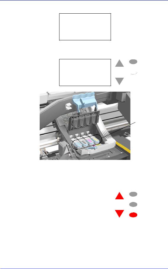
Open the Window and you will see the following message on the Front Panel:
1.Lift printhead cover
2.Check if there is ink inside printhead windows
3.Press ENTER to continue
Menu
 Back
Back
 Enter
Enter
Check for ink
Open the Carriage Cover and check if there is ink inside the Start-up Printheads. On the Front Panel you will see the following question and you will need to select the answer depending on whether the Start-up Printheads were filled with ink or not:
|
Are all printhead windows |
Menu |
|
|
|
||
|
filled with ink? |
Back |
|
|
|
|
|
|
|
|
|
|
ALL with some ink |
|
Enter |
|
NOT all with ink |
|
|
|
|
|
|
If there is ink in all of the Start-up printheads, the Printer considers that the priming procedure has been completed successfully and will proceed to the Printhead replacement process.
If you select NOT all with ink the Printer will react differently depending on the source of the problem:
HP DesignJets 500, 510 and 800 Series Printers Service Manual |
1-9 |

Troubleshooting
NOTE
NOTE
If you need to reseat the Start-up Printheads, make sure you reinsert them in the same color slot in the Carriage.
The Printer will request you to reseat the Start-up Printheads (or in the case of missing Start-up Printheads you should install them or order new ones) and then retry the priming process (if the priming process fails 3 times because of the same problem, it will display a System Error). In this situation, the problem could be the following:
1The Start-up Printheads were not installed correctly or they are missing (one or all of them).
2The Start-up Printheads do not work properly and do not allow air to flow (one or all of them).
3The Ink Supply Station fails to pressurize the Ink Cartridges. To check this, perform the Ink Supply Station test Page 4-6.
4The Ink Supply Tubes are blocked, preventing the ink from flowing correctly.
If a System Error is displayed, try the following:
1The Ink Cartridge valve is broken so the Ink Cartridge should be replaced.
2The Start-up Printhead is not working properly and allows ink to flow outside.
3The Ink Supply Tube is leaking.
The last 2 cases will be more obvious because there will be a lot of ink in the Printer (around 20 cc of ink). Remove the Ink Cartridges and release the Tubes Bracket from the Ink Supply Station and check if there is ink in this area.
For more information on this problem, refer to System Error 93:10 on Page 2-19.
1-10 |
HP DesignJets 500, 510 and 800 Series Printers Service Manual |
Troubleshooting
|
|
Using the Power Switch LED to Troubleshoot |
|
|
In certain circumstances the LED located in the power switch |
|
|
(located on the left hand side of the Printer) can help to troubleshoot |
|
|
the Printer. The LED can be OFF, ON or flashing and using different |
|
|
combinations can indicate different problems. |
|
|
You should only use the LED to troubleshoot when the Printer |
NOTE |
||
|
|
does not Power up completely. The LED may flash in other |
|
|
circumstances which are completely normal and this does not |
|
|
mean that there is a problem with the Printer. |
LED OFF |
LED ON |
LED is OFF - This indicates that the Power Supply Unit is completely dead. Try the following:
1Check that power cord is connected correctly to the Printer and to the Power Socket. Also make sure that you firmly press the Power Switch to the ON position.
2Replace the Power Supply Unit Page 8-27.
LED is ON (all the time) - This indicates that the Main PCA is completely dead. Replace the Electronics Module Page 8-24.
LED is Flashing continuously - A problem has been detected with the previous firmware upgrade. Try resending the firmware upgrade file.
LED Flashes twice every few seconds - The Printer cannot detect
HP DesignJets 500, 510 and 800 Series Printers Service Manual |
1-11 |

Troubleshooting
the Interconnect Cable. Try the following:
1Check that the Interconnect Cable is connected correctly to the Electronics Module and to the Interconnect PCA.
2If the Interconnect cable is connected correctly and the LED continues to flash twice then replace the Interconnect Cable Page 8-59.
LED Flashes 3 times every few seconds - The Printer cannot detect the Front Panel. Try the following:
1Check that the Front Panel is connected correctly to the Interconnect PCA.
2Check that the Interconnect Cable is properly connected at the both ends of the Printer.
3If the Front Panel is connected correctly and the LED continues to flash 3 times then replace the Front Panel Page 8-9.
4Replace the Interconnect Cable Page 8-59.
5Replace the Electronics Module Page 8-24.
LED Flashes 4 times every few seconds - This indicates that the Main PCA has failed. Replace the Electronics Module Page 8-24.
LED Flashes 5 times every few seconds - This indicates that the Main PCA has failed. Replace the Electronics Module Page 8-24.
1-12 |
HP DesignJets 500, 510 and 800 Series Printers Service Manual |

Troubleshooting
Using the Boot-Up Sequence to Troubleshoot
When you Power On the Printer, the Printer performs the Boot-Up sequence which initializes the major components of the Printer. If for some reason the Boot-Up sequence fails because a component has failed to initialize, the following explanations will help you to locate the failing component:
During the first phase of the Boot-up sequence (all the squares turn grey) the Printer is initializing the Operating System. If for some reason this sequence fails, try the following:
1Switch the Printer Off and wait a few minutes. Switch the Printer On again and check if the initialization sequence is successful.
2If the initialization sequence fails again, replace the Electronics Module Page 8-24.
During the second phase of the Boot-up sequence (all the squares turn black) the Printer is initializing various components (too numerous to mention). In normal circumstances, if a component fails during this sequence a System Error will appear and you should refer to Chapter 2 - System Error Codes. The following information explains what is being initialized as each square turns black:


 Initializing various components of the Main PCA.


 Initializing various components of the Main PCA.
 Initializing a portion of the Firmware.


 Initializing various components of the Main PCA.
HP DesignJets 500, 510 and 800 Series Printers Service Manual |
1-13 |

Troubleshooting


 Initializing various components of the Main PCA.


 Initializing a portion of the Firmware.
 Initializing the I/O.


 Initializing the User Interface (Front Panel menus).


 Initializing a portion of the Firmware.


 Initializing the Formatter.
 Initializing the communication between Main PCA and Formatter.


 End of initialization sequence.
Entering Service Menu at Power Up - Only for Onsite Repair
If the Printer fails to initialize completely because of a System Error and you need to use the Service Menu (Service Tests and Utilities), the Printer can be powered up in Service Mode by pressing the Up and Enter keys while switching the Printer ON. This will give you access to some of the Service Tests and Utilities without having to complete the System Initialization (if you perform some of the tests, they will need to initialize the relevant part of the System).
1-14 |
HP DesignJets 500, 510 and 800 Series Printers Service Manual |

Troubleshooting
Using the Formatter/Accessory Card LEDs to Troubleshoot
In certain circumstances the LEDs located in the Formatter or HPGL/2 Accessory Card can help to highlight certain failures. There are 3 LEDs, Red, Yellow and Green and using different combinations can indicate different problems.
LED’s on the HP-GL/2
Accessory Card
The LED’s on the Formatter can be seen without having to remove the Left Hand Cover.
LED’s on the Formatter
The yellow LED (normally flashing) indicates that the Formatter/ Accessory Card is alive. If it stops flashing, it means that the Formatter/Accessory Card has failed and should be replaced.
The green LED indicates that there is power being supplied to the
HP DesignJets 500, 510 and 800 Series Printers Service Manual |
1-15 |

Troubleshooting
Formatter/Accessory Card. If the green LED is NOT lit and the LED in the Power Switch is ON, then it could mean that the Formatter/Accessory Card is badly connected or that the Printer if switched OFF. If after reseating the Formatter/Accessory Card, the problem persists, try the following:
1Switch the Printer OFF and remove the Formatter/Accessory Card BUT leaving the LAN Card installed (if available). Switch the Printer ON. If the Printer powers up correctly and the LAN Card works properly, then try step 2. If the LAN Card doesn’t work, then try step 3.
2Switch the Printer OFF and remove the LAN Card from the current slot and install the Formatter/Accessory Card in the same slot (that was previously used by the LAN Card). Switch the Printer ON and check if the green LED in the Formatter/Accessory Card is lit. If the green LED is NOT lit, it means that the Formatter/Accessory Card is faulty and should be replaced.
If the green LED is lit, then switch the Printer OFF and install the LAN Card in the vacant slot. Switch ON the Printer and check if the LAN Card works properly. If the LAN Card does NOT work, then there is a problem with the Electronics Module and should be replaced Page 8-24.
3Switch the Printer OFF and remove the LAN Card. Switch ON the Printer and check if it initializes completely. If it initializes correctly without any problems, then the problem could be with the Electronics Module and should be replaced Page 8-24.
4If the Printer does not even start to power up (i.e. nothing seen on the Front Panel and the LED in the Power Switch is NOT flashing) without the LAN Card nor the Formatter/Accessory Card, but the power switch LED is ON (all the time) the problem could be with the Electronics Module or the Power Supply Unit.
The red LED will flash a few times when the Printer is started up but if it stays lit (all the time) or flashes continuously, then this indicates that the Formatter/Accessory Card is faulty and should be replaced.
HP Designjet 510 Series printers will only include “HPGL/2 Accessory Card (Processor Card)” installed in the Left Slot of the Electronics Module.
1-16 |
HP DesignJets 500, 510 and 800 Series Printers Service Manual |

Troubleshooting
How to Detect Problems Related to the Encoder Disk
Encoder Disk
The following information will help you detect any problems related to the Encoder Disk:
Horizontal and periodic white lines, all of them with the same width depending on the failure mode. This is a clear indication that the Encoder Disk is damaged.
System Error 56:10 - This means that you have to replace the Drive Roller Encoder Sensor Page 8-38. But, if the problem persists, replace the Encoder Disk Assembly.
System Error 81:01 - This means a Paper-Axis shutdown. If this error code appeared but was NOT caused by a paper jam, then perform the Paper Advance Test Page 4-11. If the Paper Advance Test fails during the third test, the Front Panel will display the following message:
Paper Advance test
System error 56:10
Roller encoder sensor failed
|
|
In this case, you should replace the Drive Roller Encoder Sensor |
|
|
Page 8-38. But, if the problem persists, replace the Encoder Disk |
|
|
Assembly. |
|
|
In order to remove the Encoder Disk, you must first remove the Drive |
NOTE |
||
|
|
Roller Page 8-86. |
|
|
Be very careful when assembling the Axle Spring because you could |
|
|
damage the Encoder Disk. |
|
|
Check that no air bubbles are trapped between the Encoder Disk and the |
|
|
hub once it is installed. |
HP DesignJets 500, 510 and 800 Series Printers Service Manual |
1-17 |

Troubleshooting
1-18 |
HP DesignJets 500, 510 and 800 Series Printers Service Manual |

|
|
System Error Codes |
2 |
|
Introduction 2-2
Continuable and Non-Continuable Error Codes 2-2 System Error Codes - Explanation 2-2
Accessing the Error Log Utility 2-5 01:10 2-7 01:11 2-7 01:12 2-7 01:13 2-8 02:10 2-8 02:13 2-8 03:10 2-9 04:11 2-9
05:10 Warning (Only applicable to HP DesignJet 800 Series) 2-9 05:11 2-10 08:11 2-10 11:11 2-10 11:13 2-10 12:11 2-11 21:10 2-11 21:11 2-11 22:10 2-11 41:10 2-12 41:13 2-12 42:10 2-12 43:10 2-12 43:11 2-12 56:10 2-13 56:13 2-13 61:04 2-13 61:05 2-14 64:04 2-14 71:04 2-15 71:06 2-15 72:04 2-16 73:04 2-16 79:04 2-17 81:01 2-17 81:11 2-17 85:10 2-18 86:01 2-18 86:11 2-18 86:13 2-19 87:13 2-19 93:10 2-19
HP DesignJets 500, 510 and 800 Series Printers Service Manual |
2-1 |

System Error Codes
Introduction
System error codes are hexa-decimal based numbers generally caused by internal system errors. The following pages contain a list of system error codes and their respective descriptions and recommended corrective actions. Only try one recommended action at a time and check if the error code has disappeared.
Continuable and Non-Continuable Error Codes
Some of the Error Codes are continuable, which means you can press Enter on the front-panel and continue working with the Printer. Non-Continuable Error Codes do not allow you to continue working with the Printer, in this case power the Printer OFF and ON again and see if the System Error disappears. If the Error Code reappears, then the Printer requires an on-site visit in order to resolve the problem.
|
Even though the customer can continue working with a |
NOTE |
|
|
Continuable Error Code, an on-site visit should still be planned |
|
to troubleshoot the problem. |
System Error Codes - Explanation
System Error Codes consist of 4 digits which explain which component/system is failing and what action should be taken to resolve the problem.
The following table explains the first 2 digits of the System Error Code:
Code |
Component/System |
|
|
01 |
Main PCA/Electronics Module |
02 |
Carriage/Carriage PCA |
03 |
Power Supply Unit |
04 |
Network Card |
05 |
Formatter |
06 |
Hard Disk Drive |
07 |
Interconnect PCA |
08 |
Front Panel |
11 |
Trailing Cable |
12 |
Carriage Flex Circuit |
2-2 |
HP DesignJets 500, 510 and 800 Series Printers Service Manual |
Loading...