


([FHO
: % ' ) + 9$9,, &RQWUROOHUV
Introduction ............................................................................................................................... |
4 |
Description of Devices ........................................................................................... |
4 |
Control Application................................................................................................. |
4 |
Control Provided .................................................................................................... |
7 |
Products Covered .................................................................................................. |
9 |
Organization of Manual.......................................................................................... |
9 |
Applicable Literature .............................................................................................. |
10 |
Product Names ...................................................................................................... |
10 |
Agency Listings...................................................................................................... |
11 |
Abbreviations and Definitions ................................................................................ |
12 |
Zone Control Definitions ........................................................................................ |
13 |
Variable Air Volume ATUs ................................................................................ |
13 |
Air Terminal Unit Control................................................................................... |
13 |
Pressure - Dependent And Pressure - Independent Control ............................ |
13 |
Variable Air Volume ATUs (VAV) ...................................................................... |
13 |
Single Duct Variable Air Volume (VAV) Systems.............................................. |
14 |
Pressure Dependent Throttling VAV Boxes ...................................................... |
14 |
Pressure Independent VAV Boxes.................................................................... |
14 |
Series Fan Powered VAV Boxes....................................................................... |
14 |
Parallel Fan Powered VAV boxes ..................................................................... |
14 |
Induction VAV Boxes ........................................................................................ |
14 |
Single-Duct Constant Volume Zone Reheat Air Terminal Units........................ |
15 |
Dual Duct Air Handling Systems ....................................................................... |
15 |
Variable Constant Volume (Zero Energy Band) Dual-Duct VAV Boxes ............ |
15 |
Dual Duct Constant Volume Systems ............................................................... |
15 |
Dual-duct mixing box terminal units.............................................................. |
15 |
Dual-duct constant volume mixing box terminal units .................................. |
15 |
Variable Volume/Variable Temperature (VVT).................................................. |
15 |
Single Zone Rooftop Air Handling Unit Control (CVAHU) ................................. |
16 |
Temperature and Ventilation Control ........................................................... |
16 |
Unitary Equipment Control ................................................................................ |
16 |
Construction........................................................................................................... |
16 |
Controllers......................................................................................................... |
16 |
Performance Specifications.......................................................................... |
19 |
Communications:.......................................................................................... |
19 |
Environmental .............................................................................................. |
20 |
Inputs/Outputs .............................................................................................. |
21 |
Digital Inputs................................................................................................. |
21 |
Digital Outputs:............................................................................................. |
21 |
Wall Modules .................................................................................................... |
21 |
Sensor (Duct Mount) ......................................................................................... |
21 |
Configurations........................................................................................................ |
21 |
General ............................................................................................................. |
21 |
Type of Box Fan ................................................................................................ |
21 |
Dual Duct Flow Mixing: (For setup and Calibration refer to the |
|
Dual Duct Calibration procedure in Appendix B.).................................... |
21 |
Dual Duct No Flow Mixing: (For setup and Calibration refer to the |
|
Dual Duct Calibration procedure in Appendix B.).................................... |
21 |
Dual Duct Flow Mix: (Pressure independent cooling, pressure |
|
dependent heating using one Excel 10.)................................................. |
21 |
Dual Duct Flow Mix: (Alternate Configuration).............................................. |
21 |
®U.S. Registered Trademark
Copyright © 1998 Honeywell Inc. • All rights Reserved
742949- 1

EXCEL 10 W7751B,D,F,H VAVII CONTROLLERS |
|
Dual Duct Constant Volume: (For setup and Calibration refer to the |
|
Dual Duct Calibration procedure in Appendix B.).................................... |
21 |
Dual Duct Press Flow Mix: (Pressure dependent cooling and |
|
heating using one Excel 10.)................................................................... |
21 |
Dual Duct Press Flow Mix: (Alternate Configuration) .................................. |
21 |
Dual Duct Discharge Sensor Constant Volume (pressure |
|
independent discharge using one Excel 10). .......................................... |
21 |
Dual Duct Press Flow Mix (pressure dependent cooling and |
|
heating using one Excel 10).................................................................... |
21 |
Dual Duct Pressure Independent (pressure independent heating |
|
and cooling using one Excel 10). ............................................................ |
21 |
PWM fan. ..................................................................................................... |
21 |
T7780 DDWM Binding for VAVII Controllers................................................ |
21 |
Type of Reheat Coil .......................................................................................... |
21 |
Pneumatic Valve Actuator Control ............................................................... |
21 |
Exhaust Tracking Option................................................................................... |
21 |
Occupancy Sensor............................................................................................ |
21 |
Window Open/Closed Digital Input ................................................................... |
21 |
Heat/Cool change over ..................................................................................... |
21 |
Wall Module Options......................................................................................... |
21 |
Common Temperature Control (Share Wall Module)................................... |
21 |
Sensor Options ................................................................................................. |
21 |
Pneumatic Retrofit Applications ........................................................................ |
21 |
Application Steps ............................................................................................................................... |
21 |
Overview ................................................................................................................ |
21 |
Step 1. Plan The System ....................................................................................... |
21 |
Step 2. Determine Other Bus Devices Required ................................................... |
21 |
Step 3. Lay Out Communications and Power Wiring............................................. |
21 |
E-Bus Layout..................................................................................................... |
21 |
Power Wiring..................................................................................................... |
21 |
Power Budget Calculation Example ............................................................. |
21 |
Line Loss...................................................................................................... |
21 |
Step 4. Prepare Wiring Diagrams .......................................................................... |
21 |
General Considerations .................................................................................... |
21 |
W7751B OEM Version...................................................................................... |
21 |
W7751D,F Field-Mount Versions...................................................................... |
21 |
W7751H Version............................................................................................... |
21 |
E-Bus Termination Module................................................................................ |
21 |
Step 5. Order Equipment ....................................................................................... |
21 |
Step 6. Configure Controllers ................................................................................ |
21 |
General ............................................................................................................. |
21 |
Hardware I/O Assignment ................................................................................. |
21 |
Fan Type ...................................................................................................... |
21 |
Reheat Definitions ........................................................................................ |
21 |
Reheat Type................................................................................................. |
21 |
Flow Type..................................................................................................... |
21 |
Miscellaneous............................................................................................... |
21 |
Personality Information ..................................................................................... |
21 |
Commissioning ................................................................................................. |
21 |
Job Commissioning...................................................................................... |
21 |
ID Number......................................................................................................... |
21 |
Bench Top Configuring................................................................................. |
21 |
Configuring in the Field ................................................................................ |
21 |
Configuring the Zone Manager..................................................................... |
21 |
Excel 10 VAV Controller Point Mapping............................................................ |
21 |
Step 7. Troubleshooting......................................................................................... |
21 |
Troubleshooting Excel 10 Controllers and Wall Modules ................................. |
21 |
Temperature Sensor and Setpoint Potentiometer Resistance Ranges ............ |
21 |
Alarms............................................................................................................... |
21 |
Broadcasting the Service Message................................................................... |
21 |
W7751 Controller Status LEDs ......................................................................... |
21 |
T7770C or D Wall Module Override LED .......................................................... |
21 |
T7770C,D or T7780 DDWM Bypass Pushbutton Operation ............................. |
21 |
T7780 DDWM Bypass Pushbutton ................................................................... |
21 |
74-2949–1 |
2 |

EXCEL 10 W7751B,D,F,H VAVII CONTROLLERS |
|
Appendices ............................................................................................................................... |
21 |
Appendix A. Creating a Work Bench for Configuring Excel 10 W7751D,F |
|
VAV Controllers................................................................................................. |
21 |
Appendix B. Using E-Vision to Commission a W7751 Controller. ......................... |
21 |
Job Commissioning ............................................................................................... |
21 |
ID Number.............................................................................................................. |
21 |
Bench Top Configuring ..................................................................................... |
21 |
Configuring in the Field ..................................................................................... |
21 |
Configuring the Zone Manager ......................................................................... |
21 |
Sensor Calibration............................................................................................. |
21 |
Air Flow Balancing (For Pressure Independent applications only)................... |
21 |
Procedure.......................................................................................................... |
21 |
Resetting Air Flow Calibration to Factory Defaults............................................ |
21 |
VAVII Calibration Sequence.............................................................................. |
21 |
Appendix C. Sequences of Operation................................................................... |
21 |
Common Operations. ........................................................................................ |
21 |
Room Temperature Sensor (RmTemp)........................................................ |
21 |
Remote Setpoint (RmtStptPot or DischargeAir_Sensor).............................. |
21 |
Setpoint Limits (StptLoLim and StptHiLim)................................................... |
21 |
Bypass Mode (StatusOvrride and StatusLed) .............................................. |
21 |
BypassTime.................................................................................................. |
21 |
OverrideType................................................................................................ |
21 |
OverridePriority............................................................................................. |
21 |
Standby Mode .............................................................................................. |
21 |
Window Sensor ............................................................................................ |
21 |
CAV Control ................................................................................................. |
21 |
Continuous Unoccupied Mode ..................................................................... |
21 |
Share Wall Module ....................................................................................... |
21 |
Night Purge .................................................................................................. |
21 |
Morning Warm-Up ........................................................................................ |
21 |
Smoke Control.............................................................................................. |
21 |
Demand Limit Control................................................................................... |
21 |
Start-Up ........................................................................................................ |
21 |
Air Flow Control Sequences of Operation .................................................... |
21 |
Dual Duct, Pressure Independent, with flow mixing, with cold and |
|
hot duct flow pickups (uses a satellite Excel 10 for hot duct)........................ |
21 |
Dual Duct Flow Mixing: (For setup and Calibration refer to the |
|
Dual Duct Calibration procedure in Appendix B)..................................... |
21 |
Dual Duct, Pressure Independent, without flow mixing, with cold and |
|
hot duct flow pickups (uses a satellite Excel 10 for hot duct)........................ |
21 |
Dual Duct No Flow Mixing: (For setup and Calibration refer to the |
|
Dual Duct Calibration procedure in Appendix B)..................................... |
21 |
Dual Duct, Pressure Independent cooling, Pressure Dependent heating |
|
with flow mixing, with cold duct flow pickup................................................... |
21 |
Dual Duct Press Flow Mix (pressure dependent cooling and heating |
|
using one Excel 10)................................................................................. |
21 |
Dual Duct, Pressure Independent cooling and heating, constant volume |
|
with hot and cold duct flow pickups............................................................... |
21 |
Dual Duct Constant Volume: ........................................................................ |
21 |
Dual Duct, Pressure Dependent cooling and heating, with Flow mixing |
|
and no flow pickups....................................................................................... |
21 |
Dual Duct Press Flow Mix (pressure dependent cooling and heating |
|
using one Excel 10)................................................................................. |
21 |
Dual Duct, Pressure Independent cooling and Pressure Dependent |
|
heating, with Constant Volume and Discharge Air Flow pickup.................... |
21 |
Dual Duct Discharge Sensor Constant Volume (pressure dependent |
|
cooling and heating using one Excel 10). ............................................... |
21 |
Appendix D. Complete List of Excel 10 VAVII Controller User Addresses. ........... |
21 |
Appendix E. Q7750A Excel 10 Zone Manager Point Estimating Guide................. |
21 |
Approximate Memory Size Estimating Procedure............................................. |
21 |
Appendix F. Custom Flow Pickup Tables (not Applicable for |
|
Pressure Dependent Applications).................................................................... |
21 |
Method 1. Pressure Velocity Formula ............................................................... |
21 |
Method 2. Pressure Versus Flow Graph ........................................................... |
21 |
3 |
74-2949–1 |

EXCEL 10 W7751B,D,F,H VAVII CONTROLLERS
,1752'8&7,21
'HVFULSWLRQ RI 'HYLFHV
The W7751B,D,F,H Excel 10 VAV II Box Controllers provide enhanced control solutions for single duct, dual duct and constant volume air terminal units. They feature preprogrammed heating/cooling or reheat control algorithms for standard VAV Box control applications that are selected through the E-Vision software configuration tool. They use Echelon® LonWorks® communication technology and the new Free Topology Transceiver (FTT) for greater installation flexibility. In addition, they are the first VAV Box Controllers in the marketplace from any manufacturer that use the LonMark® VAV Controller compliance profile for true openness and interoperability with third party LonMark® devices. They can be used in stand-alone applications or be used in combination with Excel 10 Zone Manager (FTT), other Excel Controllers, and the Excel Building Supervisor, to provided a complete and low cost control solution for small to large commercial buildings.
The W7751B,D,F,H Excel 10 VAV Box Controllers are configurable direct digital controllers designed for pressure independent or pressure dependent single duct VAV, dual duct VAV and constant volume air terminal unit control solutions. Four models are available including a low cost circuit board version (W7751B) for internal panel mounting, two plenum mounted controllers complete with a wiring subbase for easy field installation (W7751D and F) and the low cost W7751H Smart VAV Actuator consisting of the Excel 10 Controller that is factory mounted and wired to a 90 second ML6161B Actuator. All four of the Excel 10 VAV Box Controllers contain an integral microbridge air flow sensor that provides flow measurement for pressure independent applications. The controller configuration is selected using a personal computer and the E-Vision and CARE software configuration tools. The Excel 10 VAV Box Controllers offer many features required in todays commercial buildings including energy saving setpoint reset for electrical demand limit control, standby setpoints for setpoint reset in the occupied mode and unoccupied setpoints for both heating and cooling. The control solutions are scaleable from stand-alone installations, to a networked system using a Zone Manager as the network master or they can be fully integrated into the complete Excel 5000 system with Excel 80, 100, 500 and 600 controllers and Excel Building Supervisor. In addition, they
provide true open communication with the use of the LonMark® Controller compliance profile and the FTT for greater flexibility in network wiring and integration with third party LonMark® devices.
The T7770 are direct-wired wall modules used in conjunction with W7751B,D,F,H Controllers. The zone controlled by the W7751 Controllers will typically use a T7770 Wall Module with a temperature sensor for space temperature measurement in a minimum system configuration. Additional features available in the T7770 model include analog setpoint input, override digital input pushbutton, override status LED and E-Bus network access jack.
The T7780 Digital Display Wall Module (DDWM) has all of the features of the T7770 Wall Modules but communicates via the E-Bus.
The C7770A Air Temperature Sensor is a direct wired temperature sensor that is used to sense discharge or return air in a duct controlled by a W7751 Controller.
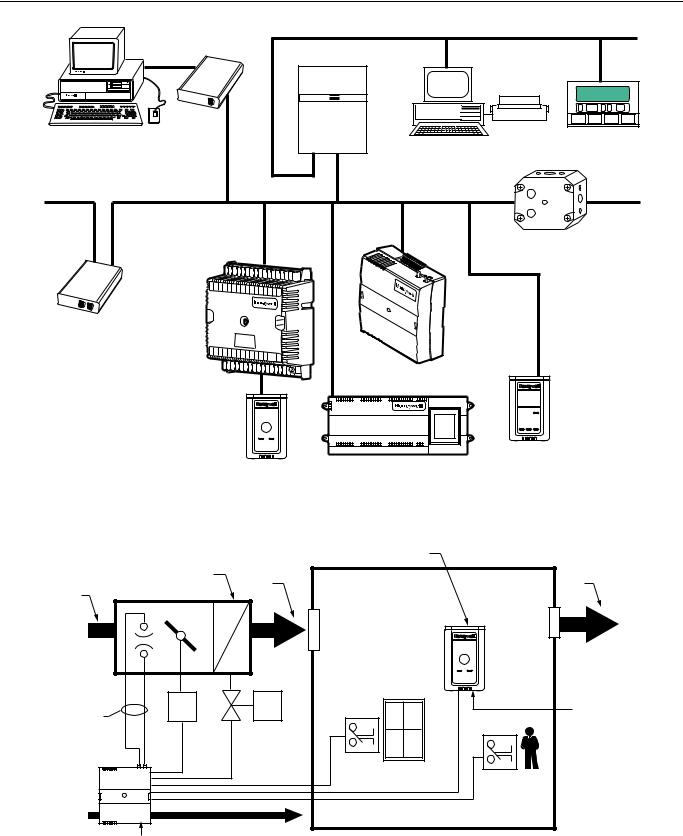
The Q7750A Excel 10 Zone Manager is a communications interface that allows devices on the E-Bus network to communicate with devices on the EXCEL 5000® System C-Bus. Fig. 1 shows an overview of a typical system layout. The Q7750A also provides some control and monitoring functions.
&RQWURO $SSOLFDWLRQ
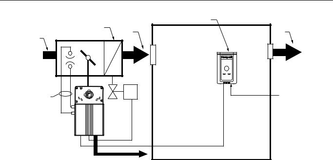
VAV systems in commercial buildings typically incorporate a central air handler that delivers a modulated volume of air at a preconditioned temperature to multiple zones. Each zone is serviced by a VAV terminal box unit. Each box incorporates an air flow pickup assembly and motorized damper with optional fan and/or reheat coil. The controller determines and regulates the air flow of conditioned air to the space. The zone being fed by the terminal box will use a T7770 Wall Module or a T7780 DDWM for space temperature determination and access to the E-Bus network for operators. Fig. 2 shows a typical VAV box control application for the W7751B,D,F Controllers. Fig. 3 shows a typical VAV box control application for the W7751H Smart VAV Actuator. Table 1 shows the capabilities of the Excel 10 VAV Box Controllers.
74-2949–1 |
4 |
|
|
EXCEL 10 W7751B,D,F,H VAVII CONTROLLERS |
||
Q7752A |
|
C-BUS COMMUNICATION NETWORK |
|
|
FTT E-BUS |
|
|
||
SERIAL |
|
|
|
|
ADAPTER |
|
|
|
|
|
EXCEL 10 |
|
|
|
|
Q7750A |
|
|
|
PERSONAL COMPUTER TOOLS |
FTT ZONE |
|
EXCEL 500 |
|
E-VISION |
MANAGER |
EXCEL BUILDING SUPERVISOR |
||
|
||||
CARE |
|
|
|
|
|
C-BUS TO E-BUS |
|
||
|
INTERFACE DEVICE |
Q7740A |
||
FTT E-BUS COMMUNICATIONS NETWORK |
FTT E-BUS COMMUNICATIONS NETWORK |
2-WAY |
||
REPEATER |
||||
31 |
30 |
29 |
28 |
27 |
26 |
25 |
24 |
23 |
22 |
|
|
|
|
|
|
|
|
|
|
21 |
20 |
19 |
|
|
|
||||||
|
|
|
|
|
|
|
|
18 |
17 |
16 |
|
EXCEL 10 |
|
Q7751A |
W7750B |
|
CVAHU |
||
FTT |
||
CONTROLLER |
||
E-BUS |
||
|
||
ROUTER |
|
1 |
2 |
3 |
4 |
5 |
6 |
|
|
|
|
|
|
|
|
|
|
|
7 |
8 |
9 |
10 |
|
|
|
|
|
|
|||||
|
|
|
|
|
|
|
|
|
11 |
12 |
13 |
14 |
15 |
J3 |
EXCEL 10 T7770
WALL MODULE
FTT E-BUS
COMMUNICATIONS
NETWORK
EXCEL 10 W7751F
PANEL PLENUM
MOUNT VERSION
VARIABLE AIR
VOLUME
CONTROLLER
EXCEL 10
W7752 FTT
FAN COIL UNIT CONTROLLER
EXCEL 10 T7780
DIGITAL DISPLAY WALL MODULE
M11817
|
|
Fig. 1. Typical system overview. |
|
|
|
TEMPERATURE SENSOR WITH |
|
|
|
REMOTE SETPOINT ADJUSTMENT |
|
|
|
AND UNOCCUPIED BYPASS |
|
|
|
OVERRIDE BUTTON |
|
|
TERMINAL HEAT |
DISCHARGE |
RETURN |
PRIMARY |
|
AIR |
AIR |
AIR TERMINAL UNIT |
|
|
|
AIR |
|
|
|
P |
M1 |
M2 |
E-BUS |
PICKUP |
|
|
|
|
|
NETWORK |
|
|
|
|
|
|
|
|
ACCESS |
|
|
WINDOW CONTACT |
|
|
|
|
OCCUPANCY |
|
|
|
CONTACT |
|
ECHELON BUS |
|
|
|
|
E-BUS NETWORK ACCESS |
M1 |
= DAMPER ACTUATOR |
|
|
|
|
|||
EXCEL 10 VAV |
M2 |
= VALVE ACTUATOR |
M11818 |
||
CONTROL MODULE W7751 |
|
|
|
||
Fig. 2. Typical W7751B,D,F VAV box control application.
5 |
74-2949–1 |
EXCEL 10 W7751B,D,F,H VAVII CONTROLLERS |
|
||
|
|
|
TEMPERATURE SENSOR |
|
|
|
WITH REMOTE SETPOINT |
|
|
|
ADJUSTMENT |
|
TERMINAL HEAT |
DISCHARGE |
RETURN |
PRIMARY |
AIR |
AIR |
|
AIR |
AIR TERMINAL UNIT |
|
|
P |
|
M1 |
E-BUS |
PICKUP |
|
||
|
NETWORK |
||
|
|
|
|
|
|
M1-REHEAT |
ACCESS |
|
|
VALVE |
|
|
|
ACTUATOR |
|
|
EXCEL 10 |
|
|
|
W7751G |
|
|
|
SMART VAV |
|
|
|
ACTUATOR |
|
|
|
E-BUS |
M11819 |
|
|
|
||
Fig. 3. Typical W7751H Smart VAV Actuator box control application (Smart VAV Actuator mounts directly on the damper shaft as represented by the dotted line). (The W7751H does not include a window contact or occupancy sensor contact terminals, which are available via the network only.)
Table 1. Excel 10 VAV Box Controller Capability.
Excel 10 VAV Box Controller |
|
|
Capability |
W7751B,D,F |
W7751H |
|
|
|
Fan |
|
|
|
|
|
None |
X |
X |
|
|
|
Series |
X |
X |
|
|
|
Parallel - Temp |
X |
X |
|
|
|
Parallel - Flow |
X |
X |
|
|
|
Parallel - PWM |
X |
X |
|
|
|
Reheat |
|
|
|
|
|
None |
X |
X |
|
|
|
One Stage Reheat |
X |
X** |
|
|
|
Two Stages Reheat |
X |
X** |
|
|
|
Three Stages Reheat |
X |
— |
|
|
|
One Stage Periph |
X |
X** |
|
|
|
Floating Reheat (Two outputs) |
X |
X** |
|
|
|
Floating Periph (Two outputs) |
X |
X** |
|
|
|
Floating Reheat then Periph |
X |
— |
(Four outputs) |
|
|
|
|
|
Floating Periph then Reheat |
X |
— |
(Four outputs) |
|
|
|
|
|
PWM Reheat (One output) |
X |
X** |
|
|
|
PWM Periph (One output) |
X |
X** |
|
|
|
PWM Reheat then Periph |
X |
X** |
(Two outputs) |
|
|
|
|
|
PWM Periph then Reheat |
X |
X** |
(Two outputs) |
|
|
|
|
|
Excel 10 VAV Box |
|
|
Controller Capability |
W7751B,D,F |
W7751H |
|
|
|
Exhaust Tracking |
|
|
|
|
|
Disabled |
X |
X |
Enabled |
X |
X |
|
|
|
Occupancy Sensor |
|
|
|
|
|
None |
X |
X |
Connected |
X |
—* |
|
|
|
Window Contact |
|
|
|
|
|
None |
X |
X |
Connected |
X |
—* |
|
|
|
Wall Module Configuration |
|
|
|
|
|
Local |
X |
X |
Shared |
X |
X |
|
|
|
Wall Module Type |
|
|
|
|
|
Sensor Only |
X |
X |
Sensor and Setpoint |
X |
X |
Sensor, Setpoint and Bypass |
X |
X |
Sensor and Bypass |
X |
X |
|
|
|
(continued)
74-2949–1 |
6 |

EXCEL 10 W7751B,D,F,H VAVII CONTROLLERS
Table 1. Excel 10 VAV Box Controller Capability
(Continued).
Excel 10 VAV Box |
|
|
Controller Capability |
W7751B,D,F |
W7751H |
|
|
|
Air Temperature Sensor |
|
|
|
|
|
20 K ohm air temperature |
X |
X |
sensors can be used in |
|
|
conjunction with wall modules |
|
|
(Either a wall module or an air |
|
|
temperature sensor can be |
|
|
used with the W7751H, but |
|
|
not both.) |
|
|
|
|
|
Dual Duct Pressure |
|
|
Independent |
|
|
|
|
|
Flow mixing |
X*** |
X*** |
Cold and hot duct flow |
|
|
pickups |
|
|
|
|
|
Without flow mixing |
X*** |
X*** |
Cold and hot duct flow |
|
|
pickups |
|
|
|
|
|
Constant volume |
X*** |
X*** |
Cold and hot duct flow |
|
|
pickups |
|
|
|
|
|
With cold duct pickup only |
X |
X |
|
|
|
Constant volume with |
X**** |
X**** |
discharge pickup only |
|
|
|
|
|
Dual Duct Pressure |
|
|
Dependent |
|
|
|
|
|
With flow mixing |
X |
X |
|
|
|
Without flow mixing |
X |
X |
|
|
|
*Available only via the network for the W7751H.
**The W7751H Smart VAV Actuator provides damper control and two configurable outputs available for two stages of reheat, floating reheat (requires two outputs), PWM Reheat or Periph (one output required), PWM Reheat and Periph (two outputs required) or one stage of reheat or Periph (can be PWM also) and a serial or parallel fan.
***These applications require two W7751 Excel 10 controllers per zone.
****Flow sensor in discharge air. The temperature control loop controls the cool damper position and the flow controls adjust the heating damper position.
&RQWURO 3URYLGHG
The W7751B,D,F,H Controllers are primarily intended for pressure independent, single or dual-duct VAV box control. Pressure independent control specifies that the individual zone terminal unit has a means for maintaining a consistent volume of air into the zone regardless of the input static pressure. The controller modulates the air flow into the zone to satisfy the Zone Temperature Setpoint. Minimum Air Flows are maintained except during emergency strategy periods or during building Unoccupied periods if using physical position stops, a MIN/MAX air flow is always maintained (see Table 2).
Pressure dependent control specifies that the damper position is controlled by space temperature only and not by a measurement of air flow volume. The amount of air delivered to the zone at any given damper position is dependent on the static pressure in the supply air duct (physical position stops, range stop pins, are used to keep the damper at a fixed position).
VAV systems generally only provide cool air to the zones; therefore, the W7751 Controller provides additional outputs for control of heating systems such as reheat coils for Heat mode or Morning warm-up mode operation. The heating equipment can be staged-resistive heating, staged 2-position (solenoid) valve, or modulated steam or hot water valve.
The possible modes of operation are listed in Table 2.
7 |
74-2949–1 |

EXCEL 10 W7751B,D,F,H VAVII CONTROLLERS
Table 2. Modes Of Operation For Excel 10 VAV Controller.
Mode |
Description |
Events Causing a Controller to Switch to This Mode |
|
|
|
Effective Occupancy (User Address: StatusOcc) |
|
|
|
|
|
OCCUPIED* |
Controller is in Occupied mode. |
Any of the following: Network input (DestSchedOcc) containing |
|
|
time-of-day schedule flag from either the Excel 10 Zone |
|
|
Manager, a C-Bus controller, an Occupancy Sensor Digital Input, |
|
|
or from Network input (DestManMode) for manual override to |
|
|
OCCUPIED mode. |
|
|
|
STANDBY* |
Controller is in Standby mode. |
Network input (DestSchedOcc) containing time-of-day schedule |
|
|
flag from the Excel 10 Zone Manager must be OCCUPIED and |
|
|
the Occupancy Sensor Digital Input must be UNOCCUPIED. |
|
|
|
UNOCCUPIED |
Controller is in Unoccupied mode. |
Network input (DestSchedOcc) containing time-of-day schedule |
|
|
flag from the Excel 10 Zone Manager, the C-Bus, or the network |
|
|
input CmdManOcc has a value of UNOCCUPIED. |
|
|
|
Override Modes (User Address: StatusOvrride) |
|
|
|
|
|
OCCUPIED* |
Controller is in Occupied mode. |
Network input (DestSchedOcc) containing time-of-day schedule |
|
|
flag from the Excel 10 Zone Manager, the C-Bus, the Occupancy |
|
|
Sensor Digital Input or from the Network input (DestManMode) |
|
|
for manual override to OCCUPIED mode. |
|
|
|
UNOCCUPIED |
Controller is in Unoccupied mode. |
Network input (DestSchedOcc) containing time-of-day schedule |
|
|
flag from the Excel 10 Zone Manager, the C-Bus, or the network |
|
|
input DestManualOcc has a value of UNOCCUPIED. |
|
|
|
BYPASS |
User-initiated Bypass of the |
Digital input (Bypass pushbutton) has been pressed, and the |
|
Unoccupied mode. |
Bypass duration timer has not yet expired, or the network input |
|
|
DestManualOcc has a value of BypassTime. |
|
|
|
NOT ASSIGNED |
No Bypass action. |
No Override input received. |
|
|
|
Operational Modes (User Address: StatusMode) |
|
|
|
|
|
START-UP AND |
Flow Diversity on power-up provides |
These modes occur on controller power-up, and after |
WAIT (followed by) |
a staggered start sequence to evenly |
downloading to the controller from E-Vision or going to auto |
FLOAT_OUT_SYNC |
apply the load to the supply fan and |
mode to manual mode (DestManMode). Temperature and flow |
|
electrical system. |
control loops are disabled. |
|
|
|
COOLING |
The Excel 10 VAV Controller is |
Network input (DestHvacMode) containing AHU operational |
|
controlling the Cooling mode. |
mode information from other E-Bus controllers that have the |
|
|
value of COOL/AUTO. |
|
|
|
HEATING |
The Excel 10 VAV Controller is |
Network input (DestHvacMode) containing AHU operational |
|
controlling the Heating mode. |
mode information from other E-Bus controllers that have the |
|
|
value of HEAT/AUTO. |
|
|
|
REHEAT |
The Excel 10 VAV Controller is |
Network input (DestHvacMode) has the value of AUTO, so that |
|
controlling the Reheating mode. |
when cool air is supplied to the box and the space temperature is |
|
|
below the Heating Setpoint, causes the Excel 10 VAV Controller |
|
|
control algorithm to energize the Reheat coil(s). |
|
|
|
MORNING |
The main AHU is supplying warm air, |
Network input (DestHvacMode) containing AHU operational |
WARM-UP |
and the box damper is set at |
mode information from E-Bus controllers that have the value of |
|
(WarmupDmprPos). |
MORNING WARM-UP. |
|
|
|
NIGHT PURGE |
The main AHU is supplying fresh |
Network input (DestHvacMode) containing AHU operational |
|
(100 percent outdoor) air, and the |
mode information from E-Bus controllers that have the value of |
|
box damper is set at |
NIGHT PURGE. |
|
(PurgeDmprPos). |
|
|
|
|
PRESSURIZE |
The box damper is set at |
Network input (DestHvacMode) containing smoke control signal |
|
(PressDmprPos). |
from E-Bus controllers that have the value of PRESSURIZE. |
|
|
|
DEPRESSURIZE |
The box damper is set at |
Network input (DestHvacMode) containing smoke control signal |
|
(DepressDmprPos). |
from E-Bus controllers that have the value of DEPRESSURIZE. |
|
|
|
FLOW TRACKING |
Temperature control is turned off. |
Configuration parameter is box type (Flow_Tracking). |
|
The box maintains a Flow Setpoint |
NOTE: See Fig. 45. |
|
based on the sum of all of the |
FlowTrackOfst (Flow Offset) determines the differential between |
|
controllers supplying the zone (the |
the boxes that are the supply air flow and the exhaust air flow. |
|
SrcBoxFlow controller provides other |
|
|
controllers with DestFlowTrack input). |
|
|
|
|
*Available only via the network for the W7751H. |
(continued) |
|
74-2949–1 |
8 |

EXCEL 10 W7751B,D,F,H VAVII CONTROLLERS
Table 2. Modes Of Operation For Excel 10 VAV Controller (Continued).
Mode |
Description |
Events Causing a Controller to Switch to This Mode |
|
|
|
MANUAL POSITION |
Box damper is set to (ManDamp). |
Typically this is done through E-Vision or XBS by setting the |
|
|
point DamperPos to Manual mode. |
|
|
|
Operational Modes (User Address: StatusMode) |
|
|
|
|
|
MANUAL FLOW |
Air Flow Setpoint is set to |
Typically this is done through E-Vision or XBS by setting the |
|
(DestManFlowSpt). |
point SupplyFlow to Manual mode. |
|
|
|
MANUAL |
See comments for FlowManState in |
¾ |
|
Appendix D, Table D7. LonMark®. |
|
|
|
|
CLOSED* |
Indicates a window is open; box |
The (Window) Digital Input contacts are open and the controller |
|
damper is set to (WinOpnDmprPos). |
is configured for a window sensor. |
|
|
|
SELF TEST |
Control algorithm is disabled; various |
The variable (TestMode) was set to TESTING. NOTE: This mode |
|
hardware tests can be performed. |
is available in Excel 10 VAV Controller versions and also include |
|
|
the W7751H Smart VAV Actuator. |
|
|
|
I/O TEST |
Control algorithm is disabled, various |
The I/O test pin/pad is shorted (see the I/O Test Mode, |
|
hardware tests can be performed |
Application Step 7. Troubleshooting). |
|
(see I/O Test Mode, Application Step |
NOTE: The I/O Test Mode is not available on the W7751H |
|
7. Troubleshooting). |
Smart VAV Actuator. |
|
|
|
FLOAT_OUT_SYNC |
Controller is synchronizing actuators. |
Control loops are temporarily suspended. NOTE: For controllers |
|
|
that enter the Unoccupied mode, its actuators are controlled and |
|
|
resynchronize during a time frame of 125 percent of the |
|
|
actuators motor speed; for example, if an actuators motor speed |
|
|
is 90 seconds, the actuator would resynchronize after 112 |
|
|
seconds once its controller entered the Unoccupied mode. |
|
|
If a controller remains in continuous Occupied mode, the |
|
|
actuators that it controls resynchronize approximately once every |
|
|
24 hours based on the CPU clock of the controller. If a controller |
|
|
remains in continuous Occupied mode it resynchronizes |
|
|
randomly during this time period of one hour. |
|
|
|
DISABLED |
Shutoff control algorithm |
Network input (DestManMode) containing AHU operational mode |
|
|
information from other E-Bus controllers that have the value of |
|
|
DISABLED. |
|
|
|
*Available only via the network for the W7751H.
3URGXFWV &RYHUHG
This System Engineering Guide describes how to apply the Excel 10 family of W7751 VAV Controllers and related accessories to typical applications. The specific devices covered include:
•W7751B,D,F,H Controllers.
•T7770A through D Wall Modules.
•T7780 Digital Display Wall Module.
•Q7750A Excel 10 Zone Manager.
•Q7751A,B Bus Router.
•Q7752A Serial Adapter.
•Q7740A,B FTT Repeaters.
•209541B FTT Termination Module.
2UJDQL]DWLRQ RI 0DQXDO
This manual is divided into three basic parts: the Introduction, the Application Steps, and the Appendices that provide supporting information. The Introduction and Application Steps 1 through 5 provide the information needed to make accurate material ordering decisions. Application Step 6 and the Appendices include configuration engineering that can be started using Excel E-Vision PC Software after the devices and accessories are ordered. Application Step 7 is troubleshooting.
The organization of the manual assumes a project is being engineered from start to finish. If an operator is adding to, or is changing an existing system, the Table of Contents can provide the relevant information.
9 |
74-2949–1 |

EXCEL 10 W7751B,D,F,H VAVII CONTROLLERS
$SSOLFDEOH /LWHUDWXUH
The following list of documents contains information related to the Excel 10 family of VAV Box Controllers and the EXCEL 5000® System in general.
Form No. |
Title |
74-2076C |
Excel 10 Technical Literature Collation |
74-2942 |
Excel 10 W7751B,D,F Controller |
|
Specification Data |
74-2953 |
Excel 10 W7751H Smart VAV Actuator |
|
Specification Data |
74-2697 |
T7770A through G Wall Module |
|
Specification Data |
74-2955 |
T7780 Digital Display Wall Module |
|
Specification Data |
74-2868 |
Excel 10 C7770A Air Temperature Sensor |
|
Specification Data |
74-2950 |
Excel 10 Q7750A, Zone Manager |
|
Specification Data |
74-2952-1 |
Excel 10 Q7751A,B Router Specification |
|
Data |
74-2954-1 |
Excel 10 Q7752A Serial Interface |
|
Specification Data |
74-2858 |
Excel 10 Q7740A,B FTT Repeaters |
|
Specification Data |
74-2951 |
Excel 10 Q7750A Zone Manager Checkout |
|
and Test Manual |
95-7504 |
Excel 10 W7751B,D,F Controller |
|
Installation Instructions |
95-7538 |
T7770A,B,C,D,E,F,G Wall Module |
|
Installation Instructions |
95-7558 |
T7780 Digital Display Wall Module |
|
Installation Instructions |
95-7509 |
Excel 10 Q7750A Zone Manager |
|
Installation Instructions. |
95-7510 |
Excel 10 Q7751A,B Router Installation |
|
Instructions |
95-7511 |
Excel 10 Q7752A Serial Interface |
|
Installation Instructions |
95-7516 |
Excel 10 SLTA Connector Cable Installation |
|
Instructions |
95-7555 |
Excel 10 Q7740A,B FTT Repeaters |
|
Installation Instructions |
95-7554 |
Excel 10 209541B Termination Module |
|
Installation Instructions |
74-2588 |
Excel E-Vision User’s Guide |
74-5587 |
CARE User’s Manual |
74-1392 |
CARE Excel 10 Zone Manager User’s |
|
Guide |
74-5577 |
CARE Icon Guide |
74-2039 |
XBS User’s Manual |
74-5018 |
XBS Application Guide |
3URGXFW 1DPHV
The W7751 Controller is available in four models:
•W7751B VAV Box Controller for OEM mounting on a VAV box.
•W7751D VAV Box Controller mounts on either a standard 4 in. by 4 in. electrical junction box or a standard 5 in. by 5 in. electrical junction box (wire passes through junction box to wiring subbase). It can also be snapped onto standard EN 50 022 DIN rail 35
mmby 7.5 mm (1-3/8 in. by 5/16 in.).
•W7751F VAV Box Controller mounts into either a panel with screws or snaps onto standard EN 50 022 DIN rail 35 mm by 7.5 mm (1-3/8 in. by 5/16 in.). Wires are terminated externally to wiring subbase.
•W7751H Smart VAV Actuator is a VAV controller that is factory mounted to an ML6161B1000 Actuator. The actuator/controller assembly is field mounted to the VAV box damper shaft similar to the mounting of a standard actuator, and the controller wiring is terminated to the screw terminals that are located under
asnap-on cover.
The T7770 Wall Module is available in five models:
•T7770A1006 Wall Module with temperature sensor. Use with Excel 5000 or Excel 10 Controllers.
•T7770A2004 Wall Module with temperature sensor and E-Bus network connection. Use with Excel 5000 or Excel 10 Controllers.
•T7770B Wall Module with temperature sensor, setpoint, and E-Bus network connection. Use with Excel 5000 or Excel 10 Controllers.
•T7770C Wall Module with temperature sensor, setpoint, Bypass button and LED, and E-Bus network connection. Use with Excel 5000 or Excel 10 Controllers.
•T7770D Wall Module with temperature sensor, Bypass button and LED, and E-Bus network connection. Use with Excel 5000 or Excel 10 Controllers.
NOTE: The T7770B,C Models are available with a relative scale plate adjustable in E-Vision °F (± 5°C).
The T7780 DDWM is available in four models:
•T7780 DDWM displays and provides space
temperature, setpoint, Occ/Unocc override, Application Mode, and Fan mode/speed selection for all Excel 10 controllers (except W7751A,C,E,G).
Other products:
•Q7750A Excel 10 Zone Manager.
•Q7751A,B Bus Router.
•Q7752A Serial Adapter.
•Q7740A,B FTT Repeaters
•209541B FTT Termination Module
•ML6161 Series 60 Damper Actuator.
•M6410A Series 60 Valve Actuator (use with V5812 or V5813 Valves).
•ML684A Series 60 Versadrive Valve Actuator (use with V5011 and V5013 Valves).
•MMC325-010 Transducer, Series 60 to pneumatic 0 to 10 psi.
•MMC325-020 Transducer, Series 60 to pneumatic 0 to 20 psi.
•ML6464A Direct Coupled Damper Actuator, 66 lb.-in. torque, Series 60.
•ML6474 Direct Coupled Damper Actuator, 132 lb.-in. torque, Series 60.
•ML6185A Direct Coupled Damper Actuator, Spring Return, Series 60.
74-2949–1 |
10 |
EXCEL 10 W7751B,D,F,H VAVII CONTROLLERS
•ML7984B Direct Coupled Valve Actuator, PWM (use with V5011 or V5013F,G Valves).
•EL7680A1008 Wall Module Infrared Occupancy Sensor.
•EL7628A1007 Ceiling Mounted Infrared Occupancy Sensor.
•EL7611A1003 Ultrasonic Occupancy Sensor.
•EL7612A1001 Ultrasonic Occupancy Sensor.
•AK3781 E-Bus (non-plenum): 22 AWG (0.325 mm2) twisted pair solid conductor, non-shielded wire (one twisted pair).
•AK3782 E-Bus (non-plenum): 22 AWG (0.325 mm2) twisted pair solid conductor, non-shielded wire (two twisted pairs).
•AK3791 E-Bus (plenum): 22 AWG (0.325 mm2) twisted pair solid conductor, non-shielded wire (one twisted pair).
•AK3792 E-Bus (plenum): 22 AWG (0.325 mm2) twisted pair solid conductor, non-shielded wire (two twisted pairs).
Refer to Table 10 in Application Step 5. Order Equipment for a complete listing of all available part numbers.
NOTE: The Q7750A Zone Manager is referred to as (E-Link) in internal software and CARE.
$JHQF\ /LVWLQJV
Table 3 provides information on agency listings for Excel 10 products.
|
|
Table 3. Agency Listings. |
|
|
|
|
|
Device |
Agency |
|
Comments |
|
|
|
|
W7751B,D,F |
UL |
Tested and listed under UL916 (file number E87741). |
|
Controllers |
|
|
|
|
|
|
|
|
CSA |
Listed (LR95329-3). |
|
|
|
|
|
|
FCC |
Complies with requirements in FCC Part 15 rules for a Class A Computing Device. |
|
|
|
Operation in a residential area may cause interference to radio or TV reception and require |
|
|
|
the operator to take steps necessary to correct the interference. |
|
|
|
|
|
|
FCC |
Complies with requirements in FCC Part 15 rules for a Class B Computing Device. |
|
|
|
Operation in a residential area can cause interference to radio or TV reception and require |
|
|
|
the operator to take steps necessary to correct the interference. |
|
|
|
|
|
W7751H Smart VAV |
UL |
Tested and listed under UL916 (file number E87741). |
|
Actuator |
|
|
|
|
|
|
|
|
cUL |
Tested and listed under UL916 (file number E87741). |
|
|
|
|
|
|
CE |
General Immunity per European Consortium standards EN50081-1 (CISPR 22 Class B) |
|
|
|
and EN 50082-1:1992 (based on Residential, Commercial, and Light Industrial). |
|
|
|
EN 61000-4-2 |
IEC 1000-4-2 (IEC 801-2) Electromagnetic Discharge. |
|
|
EN 50140, EN 50204 |
IEC 1000-4-3 (IEC 801-3) Radiated Electromagnetic Field. |
|
|
EN 61000-4-4 |
IEC 1000-4-4 (IEC 801-4) Electrical Fast Transient (Burst). |
|
|
Radiated Emissions and Conducted Emissions. |
|
|
|
EN 55022:1987 Class B. |
|
|
|
CISPR-22: 1985. |
|
|
|
|
|
|
FCC |
Complies with requirements in FCC Part 15 rules for a Class B Computing Device. |
|
|
|
Operation in a residential area may cause interference to radio or TV reception and require |
|
|
|
the operator to take steps necessary to correct the interference. |
|
|
|
|
|
T7770A through D |
UL |
(Not applicable.) |
|
Wall Modules |
|
|
|
|
|
|
|
|
CSA |
(Not applicable.) |
|
|
|
|
|
|
FCC |
(Not applicable.) |
|
|
|
|
|
T7780 DDWM |
CE |
Emissions; EN50081-1, EN55022 (CISPR 22 Class B), Immunity 50082-1 |
|
|
|
|
|
|
UL &cUL |
Tested and listed under UL916, S8L9 Energy Management Equipment. |
|
|
|
|
|
|
FCC |
Complies with requirements in FCC Part 15 rules for a Class B Computing Device. |
|
|
|
|
|
|
|
|
(contifnued) |
11 |
74-2949–1 |

EXCEL 10 W7751B,D,F,H VAVII CONTROLLERS
|
|
Table 3. Agency Listings (Continued). |
|
|
|
Device |
Agency |
Comments |
|
|
|
Q7750A Excel 10 |
UL |
Tested and listed under UL916, file number S4804 (QVAX, PAZY). |
Zone Manager |
|
|
|
|
|
|
CSA |
Listing pending. |
|
|
|
|
FCC |
Complies with requirements in FCC Part 15 rules for a Class A Computing Device. |
|
|
Operation in a residential area can cause interference to radio or TV reception and require |
|
|
the operator to take steps necessary to correct the interference. |
|
|
|
Q7751A,B Router, |
UL |
UL1784. |
Q7752A Serial |
|
|
Adapter |
|
|
|
|
|
|
CSA |
Listed. |
|
|
|
|
FCC |
Complies with requirements in FCC Part 15 rules for a Class B Computing Device. |
|
|
|
$EEUHYLDWLRQV DQG 'HILQLWLRQV
AHU - Air Handling Unit; the central fan system that includes the blower, heating equipment, cooling equipment, ventilation air equipment, and other related equipment.
Box - A VAV terminal unit box.
CAV - Constant Air Volume; a TUC that maintains a fixed air flow through the box.
CO - Carbon Monoxide. Occasionally used as a measure of indoor air quality.
CO2 - Carbon Dioxide. Often used as a measure of indoor air quality.
CARE - Computer Aided Regulation Engineering; the PC based tool used to configure C-Bus and E-Bus devices.
C-Bus -Honeywell proprietary Control Bus for communications between EXCEL 5000® System controllers and components.
CPU - Central Processing Unit; an EXCEL 5000® System controller module.
cUL - Underwriters Laboratories Canada.
CVAHU -Constant Volume AHU; refers to a type of air handler with a single-speed fan that provides a constant amount of supply air to the space it serves.
DDF - Delta Degrees Fahrenheit.
DDWM - Digital Display Wall Module.
D/X - Direct Expansion; refers to a type of mechanical cooling where refrigerant is (expanded) to its cold state, within a heat-exchanging coil that is mounted in the air stream supplied to the conditioned space.
E-Bus - Honeywell implementation of Echelon® LonWorks® network for communication among Excel 10 Controllers.
E-Bus Segment - An E-Bus section containing no more than 60 Excel 10s. Two segments can be joined together using a router.
Echelon® - The company that developed the LON® bus and the Neuron® chips used to communicate on the E-Bus.
Economizer - Refers to the mixed-air dampers that regulate the quantity of outdoor air that enters the building. In cool outdoor conditions, fresh air can be used to supplement the mechanical cooling equipment. Because this action saves energy, the dampers are often referred to as economizer dampers.
EMI - Electromagnetic Interference; electrical noise that can cause problems with communications signals.
E-Link - Refers to the Q7750A Zone Manager. This name is used in internal software and in CARE software.
EMS - Energy Management System; refers to the controllers and algorithms responsible for calculating optimum operational parameters for maximum energy savings in the building.
EEPROM - Electrically Erasable Programmable Read Only Memory; the variable storage area for saving user setpoint values and factory calibration information.
EPROM - Erasable Programmable Read Only Memory; the firmware that contains the control algorithms for the Excel 10 Controller.
Excel 10 Zone Manager - A controller that is used to interface between the C-Bus and the E-Bus. The Excel 10 Zone Manager also has the functionality of an Excel 100 Controller, but has no physical I/O points.
NOTE: The Q7750A Zone Manager can be referred to as E-Link in the internal software, CARE.
Firmware - Software stored in a nonvolatile memory medium such as an EPROM.
Floating Control - Refers to Series 60 Modulating Control of a valve or damper. Floating Control utilizes one digital output to pulse the actuator open, and another digital output to pulse it closed.
IAQ - Indoor Air Quality. Refers to the quality of the air in the conditioned space, as it relates to occupant health and comfort.
I/O - Input/Output; the physical sensors and actuators connected to a controller.
I x R - I times R or current times resistance; refers to Ohm’s Law: V = I x R.
K - Degrees Kelvin.
Level IV - Refers to a classification of digital communication wire. Formerly known as UL Level IV, but not equivalent to Category IV cable. If there is any question about wire compatibility, use Honeywell-approved cables (see Step 5 Order Equipment section).
OEM -Original Equipment Manufacturer; the company that builds the VAV boxes.
74-2949–1 |
12 |

EXCEL 10 W7751B,D,F,H VAVII CONTROLLERS
NEC - National Electrical Code; the body of standards for safe field-wiring practices.
NEMA - National Electrical Manufacturers Association; the standards developed by an organization of companies for safe field wiring practices.
Node - A Communications Connection on a network; an Excel 10 Controller is one node on the E-Bus network.
NV - Network Variable; an Excel 10 parameter that can be viewed or modified over the E-Bus network.
PC - An IBM compatible Personal Computer with 386 or higher processor and capable of running Microsoft® Windows™ Version 3.1.
Pot - Potentiometer. A variable resistance electronic component located on the T7770B,C Wall Module; used to allow user-adjusted setpoints to be input into the Excel 10 Controller.
PWM - Pulse Width Modulated output; allows analog modulating control of equipment using a digital output on the controller.
RTD - Resistance Temperature Detector; refers to a type of temperature sensor whose resistance output changes according to the temperature change of the sensing element.
Subnet - An E-Bus segment that is separated by a router from its Q7750A Zone Manager.
TOD - Time-Of-Day; the scheduling of Occupied and Unoccupied times of operation.
TCU - Terminal Control Unit; industry can refer to VAV box controllers such as the Excel 10 VAV Controller as TCUs.
TUC - Terminal Unit Controller; industry can refer to VAV box controllers such as the Excel 10 VAV Controller as TUCs.
VA - Volt Amperes; a measure of electrical power output or consumption as applies to an ac device.
Vac - Voltage alternating current; ac voltage rather than dc voltage.
VAV - Variable Air Volume; refers to either a type of air distribution system, or to the W7751 Excel 10 VAV Box Controller that controls a single zone in a variable air volume delivery system.
VOC - Volatile Organic Compound; refers to a class of common pollutants sometimes found in buildings. Sources include out-gassing of construction materials, production-line by-products, and general cleaning solvents. A VOC is occasionally used as a measure of indoor air quality.
W7751 - The model number of the Excel 10 VAV Box Controllers (also see VAV).
Wall Module - The Space Temperature Sensor and other optional controller inputs are contained in the T7770 or T7780 Wall Modules. See Application Step 5. Order Equipment for details on the various models of Wall Modules.
XBS - Excel Building Supervisor; a PC based tool for monitoring and changing parameters in C-Bus devices.
=RQH &RQWURO 'HILQLWLRQV
9DULDEOH $LU 9ROXPH $78V
Variable air volume (VAV) ATUs are commonly called VAV boxes. Each VAV box has a controller that controls the temperature of a room or zone by modulating a damper in the VAV box to vary the amount of conditioned air supplied to the zone rather than changing the temperature of the conditioned air. They are used in larger buildings that have many zones along with a central air handling fan that supplies conditioned air via a pressurized main air duct system. The central air handling fan has a separate equipment controller that controls discharge air temperature, humidity, and supply duct static pressure.
$LU 7HUPLQDO 8QLW &RQWURO
Air terminal units (ATUs) regulate the amount of conditioned air delivered to satisfy the temperature requirements of a room or space. ATUs are classified by air handling system design and are available in several configurations. ATUs may be of variable air volume or constant volume design, and may be used in single-duct or dual-duct air handling systems. ATU controls can be as basic as a room thermostat controlling a damper or a more complex direct digital controller operating a damper, a terminal fan and enabling a reheat coil. In all cases, each ATU has a controller that is used to control the environment of the room or space.
3UHVVXUH 'HSHQGHQW $QG 3UHVVXUH ,QGHSHQGHQW &RQWURO
Static pressure variations in an air handling system can affect terminal unit operation. Pressure-dependent terminal units are affected by changing duct static pressures because their damper position is determined by space temperature only. They may have mechanical or electric minimum and maximum air flow limits. Pressureindependent terminal units can automatically adjust to duct pressure changes because they contain air flow sensors and the controllers compensate for pressure changes in the main air distribution system. The damper position in pressure independent terminal units is determined by both space temperature and air flow volume.
9DULDEOH $LU 9ROXPH $78V 9$9
Variable air volume (VAV) ATUs are commonly called VAV boxes. Each VAV box has a controller that controls the temperature of a room or zone by modulating a damper in the VAV box to vary the amount of conditioned air supplied to the zone rather than changing the temperature of the conditioned air. They are used in larger buildings that have many zones along with a central air handling Unit (AHU) that supplies conditioned air via a pressurized main air duct system.
13 |
74-2949–1 |

EXCEL 10 W7751B,D,F,H VAVII CONTROLLERS
6LQJOH 'XFW 9DULDEOH $LU 9ROXPH 9$9 6\VWHPV
Single duct VAV systems are used in over 80 percent of the VAV applications and employ one main supply air duct from the central air handling system. The air handling unit supplies cool air virtually one hundred percent of the time, with the only exception being a morning warm-up cycle that is used in buildings that are not continuously occupied, that temporarily raises the discharge air temperature of the central air handling system to quickly warm the building from its unoccupied zone temperatures to the occupied zone temperatures. Since the central air handling system is usually supplying cool air, single or multiple electric reheat coils or a modulating hot water (hydronic) reheat coil are often added in the VAV box discharge air duct to reheat the cool air when the zone becomes too cold. VAV boxes with reheat coils typically have a series or parallel fan in the VAV box to ensure air flow across the coil in the heating mode.
3UHVVXUH 'HSHQGHQW 7KURWWOLQJ 9$9 %R[HV
Pressure dependent throttling VAV boxes are the simplest and least expensive ATU. A controller modulates a damper actuator according to the temperature in the zone. The pressure dependent VAV box usually has minimum and/or maximum damper position setpoint stops in the controller for limiting air volume. Because the unit is pressure dependent, the volume of air distributed to the zone at any given space temperature varies with the supply duct static pressure at the inlet of the VAV box. Maintaining a stable duct static pressure is important for proper operation and proper setting of the minimum damper position setpoint stop is essential for adequate circulation. When reheat coils and/or finned tube radiation are used the controller will set the damper position at a minimum position during the heating mode to ensure some air flow into the space and optimize heat transfer from the reheat coil. Pressure dependent VAV boxes are used in smaller buildings or in areas of larger buildings where the supply duct static pressure is low and stable.
3UHVVXUH ,QGHSHQGHQW 9$9 %R[HV
Pressure-independent or variable constant-volume VAV boxes are essentially air flow control devices that deliver a constant volume of air to a conditioned space at a given temperature despite a varying supply duct static pressure. An air flow sensor in the inlet of the VAV box is used to measure the volume of air and the VAV box controller resets the air flow volume setpoint as the thermal load changes in the space. Therefore, a pressure independent VAV box controller provides two control sequences; zone temperature control and terminal unit air flow control. The controller usually has a minimum air flow setpoint to maintain air flow at light load conditions and a maximum air flow setpoint to limit the air flow to meet the design conditions for the zone. A single zone sensor can be used to control multiple VAV boxes with differing volume ratings. When reheat coils and/or finned tube radiation are used with this unit the controller will lower the air flow setpoint during the heating mode to ensure air flow into the room and optimize heat transfer from the reheat coil. Pressure independent VAV boxes are used in buildings with larger air handling systems that have constant duct static pressure fluctuations due to the large number of zones.
6HULHV )DQ 3RZHUHG 9$9 %R[HV
Series Fan-powered VAV boxes are similar to pressure dependent and/or pressure independent VAV boxes, except they include an integral fan in series with the VAV box discharge duct that recirculates space air at constant volume and enhances the air distribution in the zone. Primary air is modulated by the VAV box damper to meet space demand for cooling and as primary air modulates down, more plenum air is drawn in by the fan to maintain a constant discharge volume to the zone. Typically the series fan is on continuously during occupied hours, or it can be programmed to be activated as primary air decreases to ensure adequate air circulation. In addition to enhancing air distribution, the units serving the perimeter area of a building usually include a reheat coil that is sequenced with the primary air damper to supply heat when required. When the primary air system is not operating (nighttime or unoccupied control mode), the night operating mode of the controller enables the fan and the reheat coil to maintain the lower unoccupied temperature setpoint in the space. Series Fan Powered VAV boxes can be pressure independent or pressure dependent.
3DUDOOHO )DQ 3RZHUHG 9$9 ER[HV
Parallel Fan Powered VAV boxes or Bypass Fan Induction Terminal Units are similar to Series Fan-powered VAV terminal units, except the fan is located in the return plenum and does not run continuously during occupied hours. When the zone temperature is low and the need for primary air decreases, the controller modulates the primary air damper to a minimum and enables the fan, which recirculates warm air from the return plenum into the zone acting as the first stage of reheat. If a reheat coil is used the fan is cycled on when the reheat coil is enabled. As the space warms, the reheat valve closes and the fan cycles off as the primary air damper opens to allow delivery of conditioned air from the air handling system. When heating is required in the unoccupied mode, the fan at the central air handling system remains off , the VAV box fan and the reheat coil are enabled and the zone is heated to a reduced night setback temperature using air from the return air plenum. Parallel Fan Powered VAV boxes can be pressure independent or pressure dependent.
,QGXFWLRQ 9$9 %R[HV
Induction VAV boxes use induced return air as the reheat medium which means no parallel fan is present in the VAV box. Induction VAV boxes are usually installed above the ceiling and draw return air from the plenum created by a false ceiling. The VAV box controller uses an air flow sensor for controlling air flow and a room sensor for controlling room temperature similar to pressure independent VAV boxes. The volume of air coming through the primary damper is controlled by positioning both dampers simultaneously so that as the primary air damper closes, the return air damper opens. Return air is thus drawn into the unit and recirculated into the space. Like pressure independent VAV boxes the controller resets the air flow setpoint of the controller as the thermal load changes in the conditioned space. For extremely cold design conditions, a reheat coil can be added.
74-2949–1 |
14 |

EXCEL 10 W7751B,D,F,H VAVII CONTROLLERS
The induction VAV ATU maintains satisfactory air motion at lower loads than a throttling VAV box can, however, the wide use of Parallel Fan Powered VAV boxes has now limited the use of Induction VAV boxes.
6LQJOH 'XFW &RQVWDQW 9ROXPH =RQH 5HKHDW $LU 7HUPLQDO 8QLWV
Single-Duct Constant Volume Zone Reheat Systems are used in low static pressure systems and have a heating coil (hot water, steam, or electric) in the branch supply duct to each zone. The central air-handling unit supplies constant temperature air and a manual balancing damper in each zone is set in a fixed position to determine the amount of air delivered to that zone. The volume of air delivered to each zone will change as the static pressure of the supply duct changes, however, in low static pressure systems the changes in the supply duct static pressure are small and do not have a dramatic effect on the amount air delivered to the zone. The control strategy used in single zone reheat systems is simple and involves activating electric heat or positioning a valve in conjunction to the zone temperature. In most cases this is accomplished using a simple space thermostat. However, direct digital controllers can be used in these cases to control multiple zone valve positions the reheat coil valve (or electric heating elements) as required to maintain space condition.
'XDO 'XFW $LU +DQGOLQJ 6\VWHPV
In a dual-duct air handling system, supply air is divided at the central fan and hot air and cold air flow through separate ducts to the perimeter zones in the building. Dual-duct terminal units are essentially mixing boxes with two supply inlets and one discharge outlet. The air is allowed to mix in the mixing box section and is discharged out of a single duct into the zone. Since a source of heating is available reheat coils are not used in the zone. Basic dual-duct mixing systems were not economical because supply air was cooled and heated year round and modern energy codes prohibited their use in many cities in the U.S. except in critical applications like hospitals, nursing homes, etc. However, with direct digital controllers and networked systems the individual zone data can be used to reset hot and cold duct temperatures as needed, allowing dual duct systems to be used more often in todays applications. Dual duct systems are often used in conjunction with single duct systems in the same building.
9DULDEOH &RQVWDQW 9ROXPH =HUR (QHUJ\ %DQG 'XDO 'XFW 9$9 %R[HV
Variable Constant Volume (Zero Energy Band) Dual-Duct VAV Boxes have inlet dampers (with individual damper actuators and air flow sensors) on the cooling and heating supply ducts. The air flow is pressure independent and the Dual Duct VAV Box controller uses the zone temperature to determine the required flow of hot and cold air from the respective ducts into the mixing box and resets the hot duct and cold duct air flow setpoints in sequence as space load changes. The Zero Energy Band (ZEB) is an energy conservation technique that allows temperatures to float between programmable settings to prevent the consumption of heating or cooling energy while the temperature is in this range. As space temperature rises to approach the controller setpoint, the hot air flow volume drops to zero. If space temperature continues to rise
through the ZEB, the output signal from the controller modulates the cold-air damper open. The controller maintains adjustable minimum flows for ventilation, with no overlap of damper operations, during the ZEB when neither heating nor cooling is required. For example, if a zone had a setpoint of 74 degrees and a zero energy band of 2 degrees then the zone temperature would be allowed to float between 73 degrees and 75 degrees before the controller would use hot air to heat the zone or cool air to cool the zone. When the ZEB technique is properly used the comfort of the occupants is not sacrificed in the process of saving energy.
'XDO 'XFW &RQVWDQW 9ROXPH 6\VWHPV
Dual-duct mixing box terminal units
Dual-duct mixing box terminal units generally apply to lowstatic pressure systems that require large amounts of ventilation. The warm duct damper and the cool duct damper are linked to operate in reverse of each other from a single damper actuator. The controller positions the mixing dampers through a damper actuator to mix warm and cool supply air to maintain space condition. Discharge air quantity depends on the static pressure in each supply duct at that location.
Dual-duct constant volume mixing box terminal units
Dual-duct constant volume mixing box terminal units are typically used on high-static-pressure systems where the air flow quantity to each space is critical. The units are the same as those described in the previous paragraph, except that they include either an integral mechanical constant volume regulator or an air flow constant volume control furnished by the unit manufacturer to change the damper position to maintain a constant air flow volume with changes in duct static pressure.
9DULDEOH 9ROXPH 9DULDEOH 7HPSHUDWXUH 997
VVT systems are also called commercial zoning systems and use a constant volume air supply (roof top unit, heat pump, small air handler) with heating, cooling and economizer functions and vary the flow rates and supplyair temperature into smaller, damper-controlled zones through a single duct distribution system. Each zone damper is modulated based on space temperature. However, damper control is based only on zone temperature and there is no flow control at the zone level as there is in a pressure independent variable air volume (VAV) system. Typically, the zone damper is modulated using an analog signal, providing excellent zone temperature control. A method of providing feedback of zone demand is provided which allows a controller at the rooftop to provide the minimum required amounts of heating and cooling (using economizer when acceptable) based on zone demand.
Because a number of zone dampers can possibly be closed, there needs to be a way to relieve pressure in the supply duct. A bypass damper is normally added in a duct between the supply and return ducts to relieve pressure. The pressure relief damper is normally controlled by sensing supply duct pressure and opening to vent supply air directly to return. This is one difference between a commercial zoning system and true VAV. A true VAV air handler actually varies air volume through the blower.
15 |
74-2949–1 |

EXCEL 10 W7751B,D,F,H VAVII CONTROLLERS
VVT makes it possible to operate a single-zone heating/cooling unit with multiple-zones and is often used in smaller buildings. Small buildings are not appropriate for VAV systems because the heating and cooling loads are not large enough for a VAV system to operate properly. VVT systems also cost less than VAV systems due to the use of constant volume packaged units, lower pressure ductwork, and they often do not require expensive perimeter heat. The main difference between VAV and VVT is the fact that VAV systems vary the amount of air entering a zone and not the temperature, where a VVT system varies both the amount of air and the temperature of the air entering the zone.
6LQJOH =RQH 5RRIWRS $LU +DQGOLQJ 8QLW &RQWURO&9$+8
Single-zone systems use a Constant Volume Air-Handling Unit (CVAHU) which are usually factory-packaged units mounted on the rooftop of the building, however, single zone air handling units can also be located in a mechanical room of buildings. Single zone units are used in smaller buildings, buildings that have a uniform heating/cooling load in large open zones, or in zones that have special comfort requirements that are different from other areas of the building. The building must also have the space available for the associated air handling equipment. Typical installations include; office/warehouse buildings, large open buildings such as supermarkets, restaurants, and ballrooms and lobbies of large buildings and hotels. Since single zone units are associated with only one zone, many single zone air handling units can be installed in a building. Fan volume control, as found in Variable Air Volume systems is not required, because fan volume and duct static pressure are set by the manufacturer to meet the design needs of the zone.
Temperature and Ventilation Control
A single space controller or thermostat controls the heating coil, ventilation dampers, and cooling coil in sequence as thermal load varies in the conditioned space. On rooftop mounted units the heating coils are typically electric and the cooling is by a self contained air-conditioning system using direct expansion cooling coils. However, single zone air handling systems that are located in a mechanical room of a building often employ hot water (hydronic) heating coils and use chilled water coils for cooling. The ventilation dampers (Outdoor air, Return air, and Exhaust air) are controlled to use outdoor air for the first-stage cooling when the conditions are appropriate. When outdoor air temperature or heat content (enthalpy) rises to the point that it can no longer be used for cooling, an outdoor air limit control overrides the signal to the ventilation dampers and moves them to the minimum ventilation position, as determined by the minimum positioning switch or the minimum position setpoint in the controller. Indoor air quality control is also accomplished with the Single Zone controller using sensors and control strategies that increase the minimum position of the outdoor air damper to allow more fresh air into the building when the indoor air quality is poor. A zero energy band often separates the heating and cooling control ranges, thus saving energy.
8QLWDU\ (TXLSPHQW &RQWURO
Unitary equipment includes natural convection units, radiant panels, unit heaters, unit ventilators, fan coil units, and heat pumps. Unitary equipment does not require a central fan. Depending on design, unitary equipment may perform one or all of the functions of HVAC - ventilation, filtration, heating, cooling, humidification and distribution. Unitary equipment frequently requires a distribution system for steam or hot and/or chilled water.
Control of unitary equipment varies with system design. Typically, a room thermostat provides a signal to a controlled device to regulate the unit. The unit may use a day/night thermostat for operation at lower setpoints during unoccupied hours. If the unit has a fan, a time clock may be used to turn the fan off at night, and a night thermostat may be used to control the temperature within night limits. When DDC control is used all of the thermostat and time clock functionality is contained in the controller.
&RQVWUXFWLRQ
&RQWUROOHUV
The Excel 10 VAV Controller is available in four different models. The W7751B circuit board is ready to be snapped into a section of standard 3.25 in. (82 mm) by 9 in. (228 mm) snaptrack, part number 207912. The W7751B model is intended for OEM installation on VAV boxes at the factory. Connections to the wall module terminals
(19 through 23) and the E-Bus communications terminals (29 and 30) are made at screw terminal blocks. Connection for access to the E-Bus is provided by plugging the connector into the communications jack. All other connections are made with quarter inch (6.35 mm) quick connects. See Fig. 4.
The W7751D and W7751F models both use the identical 5 in. by 5 in. circuit board contained in the housing cover. This cover can plug into either the W7751D or F Subbase. The W7751D Subbase allows screw terminations to be made on the inside. This subbase either mounts on a standard 4 in. by 4 in. or a standard 5 in. by 5 in. electrical junction box. It can also be snapped onto standard
EN 50 022 DIN rail 35 mm by 7.5 mm (1-3/8 in. by
5/16 in.). For W7751D, see Fig. 5. The W7751F Subbase provides screw terminations to be made on the outside. This subbase either mounts on a panel with screws or snaps onto standard EN 50 022 DIN rail 35 mm by 7.5 mm (1-3/8 in. by 5/16 in.). DIN rail is available through local suppliers. Wires are attached to screw terminal blocks on the top and bottom of the subbase. For W7751F,
see Fig. 6.
The W7751H Smart VAV Actuator is a physically smaller Excel 10 VAV Controller. The controller enclosure, which contains the controller circuit board, is constructed of a sheet metal housing and a plastic snap-on cover. The sheet metal housing is attached at the factory to the ML6161B Actuator and has two 1/2 in. (13 mm) knockouts that are compatible with 1/2 in. (13 mm) or 3/4 in. (19 mm) conduit, see Fig. 7. The actuator on the Smart VAV Actuator is field mounted to the VAV box damper shaft and its controller wiring is terminated to screw terminals located at the bottom under a snap-on cover.
74-2949–1 |
16 |
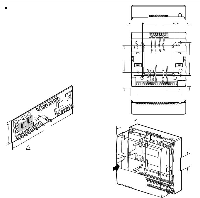
 CAUTION
W7751B,D,F Controllers must be mounted vertically as shown in Fig. 4 through 6. Vertical mounting assures adequate air flow for proper heat dissipation in the controller.
The W7751H Smart VAV Actuator is intended for horizontal shaft mounting only for heat dissipation needs.
IMPORTANT
If controller flow sensors are connected to unusually dusty or dirty environments, a 5-micron disposable air filter is recommended for use in the high pressure line (marked as +) connected to the air flow pickup. This applies to all controller models. See Table 10 for filter ordering information.
P1
P2
|
+ |
– |
P |
1
9 (228)
3
(76)
W7751B
1KEEP WIRING ROUTED AWAY FROM THIS HIGH RADIATION AREA TO AVOID INTERFERENCE PROBLEMS WITH OTHER EQUIPMENT.
M11820
Fig. 4. W7751B construction in in. (mm).
EXCEL 10 W7751B,D,F,H VAVII CONTROLLERS
1-3/32 |
4 X 4 |
3/4 |
(28) |
MOUNTING |
(19) |
|
HOLES |
|
5 X 5
MOUNTING
HOLES
3-7/16
(87)
1-1/2 |
1-3/32 |
|
(38) |
||
(28) |
||
|
 1/2
1/2  4-21/32 (118) (13)
(60)
2 |
-11/32 |
|
1 |
-3/8 |
(35) |
|
RAIL |
|||
|
|||
MOUNTING |
|||
DIN |
|
||
|
SLOT |
||
M11821
Fig. 5. W7751D construction in in. (mm).
17 |
74-2949–1 |

EXCEL 10 W7751B,D,F,H VAVII CONTROLLERS
1-3/32 |
4 X 4 |
3/4 |
(28) |
MOUNTING |
(19) |
|
HOLES |
|
5 X 5
MOUNTING
HOLES
3-7/16
(87)
1-1/2 |
1-3/32 |
|
(38) |
||
(28) |
||
|
 1/2
1/2  4-21/32 (118) (13)
(60)
2 |
-11/32 |
|
|
|
-3/8 |
(35) |
|
1 |
RAIL |
|
|
|||
|
|
||
|
MOUNTING |
||
|
DIN |
|
|
|
|
SLOT |
|
|
|
|
|
|
|
|
|
M11822
Fig. 6. W7751F construction in in. (mm).
74-2949–1 |
18 |
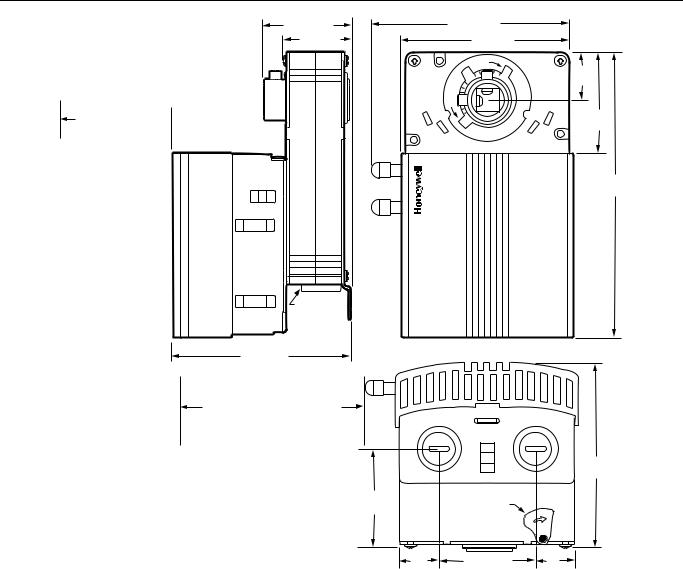
EXCEL 10 W7751B,D,F,H VAVII CONTROLLERS
MAINTAIN A MINIMUM DISTANCE OF 3 IN. (76 MM) FROM OTHER  DEVICES OR PANELS FOR REMOVING CONTROLLER COVER
1-13/16 (46) |
|
4-1/16 |
(103) |
|
1-5/16 (33) |
|
|
3-5/8 (92) |
|
|
|
|
CW |
|
|
|
|
|
1 |
|
|
|
|
(25) |
|
60° |
CCW |
|
60° |
|
|
|
||
|
|
CW |
CCW |
1-13/16 |
|
|
|
|
(46) |
|
|
45° |
45° |
|
5-7/8
(149)
DE-CLUTCH
LEVER
3-3/4 (95)
MAINTAIN A MINIMUM DISTANCE
OF 4 IN (100 MM) FROM OTHER
DEVICES OR PANELS FOR
ATTACHING PNEUMATIC AIR
FLOW TUBING
|
|
|
3-3/4 |
|
|
|
(95) |
2-1/8 |
DE-CLUTCH |
|
|
LEVER |
|
|
|
(54) |
|
|
|
|
|
|
|
3/4 |
1-15/16 (49) |
3/4 |
M10523 |
(19) |
|
(19) |
Fig. 7. W7751H construction in in. (mm).
Performance Specifications
Power:
24 Vac with a minimum of 20 Vac and a maximum of 30 Vac at either 50 or 60 Hz.
CPU:
Motorola or Toshiba 3150 Neuron® processor, containing three eight-bit CPU’s. Each Neuron has a unique 48-bit network identification number.
Memory Capacity:
64K ROM/PROM in W7751B,D,F,H
512 EEPROM
2K RAM
Specified Space Temperature Sensing Range:
45° to 99°F (7° to 37°C) with an allowable control setpoint range from 50° to 90°F (10° to 32°C) when initiated from the network and 55° to 85°F (13° to 29°C) when configured and connected to a T7770 Wall Module or T7780 DDWM.
Communications
The W7751B,D,F,H Controller uses a transformer-coupled communications port with differential Manchester-encoded data at 78 kilobits per second (kbs). The transformercoupled communications interface offers a much higher degree of common-mode noise rejection while ensuring dc isolation.
Approved cable types for E-Bus communications wiring is Level IV 22 AWG (0.34 mm2) plenum or non-plenum rated unshielded, twisted pair, solid conductor wire. For nonplenum areas, U.S. part AK3781 (one pair) or U.S. part AK3782 (two pair) can be used. In plenum areas, U.S. part AK3791 (one pair) or U.S. part AK3792 (two pair) can be used (see Tables 9 and 10 for part numbers). Contact Echelon® Corp. Technical Support for the recommended vendors of Echelon® approved cables.
19 |
74-2949–1 |
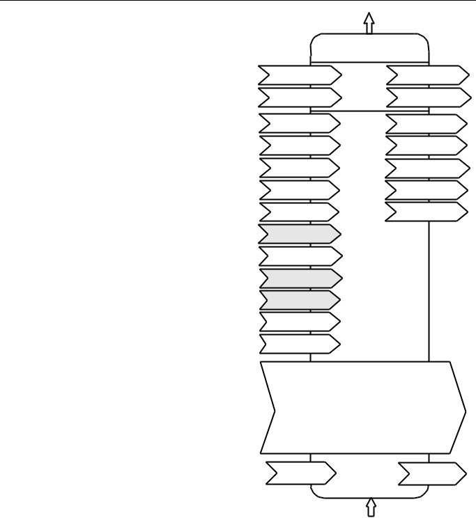
EXCEL 10 W7751B,D,F,H VAVII CONTROLLERS
The FTT supports a polarity insensitive, free topology wiring scheme that supports star, loop, and/or bus wiring. The maximum bus length when using a combination of star, loop, and bus wiring (singly terminated) is 1640 ft (500m) with the maximum node to node length of 1312 ft (400m). In the event that the limits on the number of nodes or total wire length is exceeded, then a 2-way repeater (Q7740A) can be used to double the node count and the network length or a 4-way repeater (Q7740B) can quadruple the node count and the network length. The maximum number of repeaters per segment is one. A Q7751A E-Bus Router can also be used to effectively double the maximum bus length. The advantage of using the router is that it will segregate traffic to a segment whereas with the repeater all traffic is repeated on each segment. On a doubly terminated E-Bus utilizing bus wiring (continuous daisy-chain with no stubs or taps from the main backbone) the maximum bus length is 4593 ft (1400m) with the maximum node to node length of 3773 ft (1150m).
FTT networks are very flexible and convenient to install and maintain, but it is imperative, to carefully plan the network layout, and create and maintain accurate documentation. Unknown or inaccurate wire run lengths, node to node distances, node counts, total wire length, and misplaced or missing terminators can cause poor network performance. Refer to E-Bus Wiring Guidelines form, 74-2865 for complete description of network topology rules.
LonMark® Functional Profile
W7751 Controllers support the LonMark® Functional
Profile number 8010 VAV Controller, version 1.0
(see Fig. 8).
Environmental
Operating Temperature:
-40° to 150°F (-40° to 65.5°C).
Shipping Temperature:
-40° to 150°F (-40° to 65.5°C).
Relative Humidity:
5 percent to 95 percent noncondensing.
Vibration:
Rated V2 level compliant.
Hardware:
The Excel 10 VAV Box Controllers are available in four models, the W7751B circuit board only, W7751D Plenum version with internal screw connections an the subbase for conduit installations, W7751F Plenum version with external screw connections on the subbase for nonconduit installations, and the W7751H Smart VAV Actuator which in an Excel 10 VAV Box Controller mounted and wired to a ML6161B (90 second) actuator.
Hardware
Outputs
VAV Device
Object Type # 8010
nv1 |
|
nviSpaceTemp |
|
|
|
|
nv3 |
|
nvoSpaceTemp |
|||
|
SNVT_temp_p |
Mandatory |
|
SNVT_ temp_p |
||||||||
|
|
|
|
|||||||||
|
|
|
|
|
|
|
|
|
||||
|
|
nviSetPoint |
Network |
nv4 |
|
nvoUnitStatus |
||||||
|
|
|
||||||||||
nv2 |
|
Variables |
|
|||||||||
|
SNVT_temp_p |
|
SNVT_hvac_status |
|||||||||
nv5 |
|
nviApplicMode |
|
|
|
|
nv16 |
|
nvoEffectSetPt |
|||
|
|
|
|
|
|
|||||||
|
|
|
|
|
|
|||||||
|
|
SNVT_hvac_mode |
|
|
|
|
|
|
SNVT_ temp_p |
|||
nv6 |
|
nviManOverride |
|
|
|
|
nv17 |
|
nvoFlowControlPt |
|||
|
|
|
|
|
|
|||||||
|
SNVT_hvac_overid |
|
|
|
|
|
SNVT_ flow |
|||||
nv7 |
|
nviSetpointOffset |
Optional |
nv18 |
|
nvoBoxFlow |
||||||
|
|
|||||||||||
|
SNVT_ temp_p |
|
SNVT_ flow |
|||||||||
|
|
nviOccCmd |
Network |
|
|
nvoTerminalLoad |
||||||
|
|
|
|
|||||||||
nv8 |
|
Variables |
nv19 |
|
||||||||
|
SNVT_occupancy |
|
SNVT_lev_percent |
|||||||||
nv9 |
|
nviEnergCmd |
|
|
|
|
nv20 |
|
nviEnergyHoldOff |
|||
|
|
|
|
|
|
|||||||
|
|
|
|
|
|
|||||||
|
SNVT_hvac_energ |
|
|
|
|
|
SNVT_switch |
|||||
nv10 |
|
nviBoxFlow |
|
|
|
|
|
|
|
|
||
|
|
|
|
|
|
|
|
|
||||
|
SNVT_ flow |
|
|
|
|
|
|
|
|
|||
nv11 |
|
nviEnergyHoldOff |
|
|
|
|
|
|
|
|
||
|
|
|
|
|
|
|
|
|
||||
|
|
|
|
|
|
|
|
|
||||
|
|
SNVT_switch |
|
|
|
|
|
|
|
|
||
nv12 |
|
nviFanSpeed |
|
|
|
|
|
|
|
|
||
|
|
|
|
|
|
|
|
|
||||
|
SNVT_switch |
|
|
|
|
|
|
|
|
|||
|
|
|
|
|
|
|
|
|
|
|||
nv13 |
|
nviCO2 |
|
|
|
|
|
|
|
|
||
|
|
|
|
|
|
|
|
|
||||
|
|
|
|
|
|
|
|
|
||||
|
SNVT_ppm |
|
|
|
|
|
|
|
|
|||
|
|
|
|
|
|
|
|
|
|
|||
nv14 |
|
nviHeaterOverid |
|
|
|
|
|
|
|
|
||
|
|
|
|
|
|
|
|
|
||||
|
|
|
|
|
|
|
|
|
||||
|
SNVT_switch |
|
|
|
|
|
|
|
|
|||
|
|
|
|
|
|
|
|
|
|
|||
nv15 |
|
nviDuctIn Temp |
|
|
|
|
|
|
|
|
||
|
|
|
|
|
|
|
|
|
||||
|
|
|
|
|
|
|
|
|
||||
|
SNVT_temp_p |
|
|
|
|
|
|
|
|
|||
|
|
|
|
|
|
|
|
|
|
|||
|
|
|
|
|
|
|
|
|
||||
|
|
|
|
|
|
|
|
|
|
|
|
|
|
|
|
|
Configuration Properties |
||||||||
|
|
|
nc49 - Send Heartbeat |
(mandatory) |
||||||||
|
|
|
nc60 - Occupancy Temperature Setpoints (mandatory) |
|||||||||
|
|
|
nc48 - Maximum Receive Time |
(optional) |
||||||||
|
|
|
nc52 - Minimum Send Time |
|
|
(optional) |
||||||
|
|
|
nc17 - Location |
|
|
|
|
(optional) |
||||
|
|
|
nc46 - Duct Area |
|
|
|
|
(optional) |
||||
|
|
|
nc54 - Minimum Flow |
(mandatory) |
||||||||
|
|
|
nc51 - Maximum Flow |
(mandatory) |
||||||||
|
|
|
nc55 - Minimum Flow for Heat |
|
(optional) |
|||||||
|
|
|
nc56 - Minimum Flow Standby |
|
(optional) |
|||||||
|
|
|
nc57 - Nominal Flow |
|
|
|
(optional) |
|||||
|
|
|
nc66 - VAV gain |
|
|
|
|
(optional) |
||||
|
|
|
|
|
|
|
|
|
|
|
|
|
Manufacturer
Defined
Section
Hardware
Input |
M11823 |
|
Fig. 8. Functional profile of LonMark® compliant VAV object details (variables not implemented in Excel 10 VAVII are greyed).
74-2949–1 |
20 |
EXCEL 10 W7751B,D,F,H VAVII CONTROLLERS
Inputs/Outputs
The W7751B,D,F and H controllers have the following inputs and outputs:
Analog inputs - 4 total on W7751B,D,F, 3 total on
W7751H.
Space temperature sensor (fixed location) - T7770 A through D or T7780 DDWM
Duct velocity pressure sensor (fixed location)- Microbridge 0-2 inch velocity pressure sensor
Configurable analog input options, 2 from the 3 listed below on W7751B,D,F, 1 from the 3 listed below for W7751H.
·Setpoint Potentiometer:
55° to 85°F (13° to 29.5°C) )—(9846 to 1290 ohms).
·Discharge Air Temperature Type: RTD (NTC).
Supported Sensors: C7770A1006, C7031C1031, C7031B1033, C7031J1050.
·Supply Air Temperature Type: RTD (NTC).
Supported Sensors: C7770A1006, C7031C1031, C7031B1033.
NOTE: The C7770 or C7031 Air Temperature Sensors or the setpoint potentiometer options are selectable in CARE/E-Vision. (Either one or the other, but not both are allowed on the W7751H.)
Digital Inputs
5 total on W7751B,D,F, 1 on the W7751H (reserved for the wall module Bypass pushbutton). Dry-contact inputs are sensed using a 9 milliamp at 4.8 volts detection circuit. It is very important that the device used contains high quality, non-corroding contacts with resistivity that does not degrade; that is, increase over time. Use noble metal (such as gold or silver), pimpled or sealed contacts to assure consistent, long-term operation.
·Wall Module Bypass Pushbutton—Momentary DI (Fixed location - See Appendix B—Sequences of Operation for bypass details.)
·Hardware test (Fixed location - not available on the W7751H).
·Three of the following Digital Inputs (DIs) can be configured when using the W7751B,D,F, (not available on the W7751H):
Window Monitor—Contact Closed = Window is Closed Occupancy Switch—Contact Closed = Room is Occupied; Contact Open = Room is Unoccupied Heat/Cool change over—Contact Closed = Heat Monitoring input—Contact Closed = input off or closed (input reportable on network).
Digital Outputs:
8 total on W7751B,D,F (configurable locations), 4 total on W7751H (2 fixed position damper outputs and 2 configurable outputs). Configurable digital output options.
¾Floating damper open (fixed location on W7751H)
¾Floating damper closed (fixed location on W7751H)
¾Reheat types
Reheat (floating) valve open Reheat (floating) valve closed PWM
Stage 1
Stage 2 or Three stage binary control Stage 3 (not available on W7751H)
¾Peripheral Heating types
Peripheral heat (floating) valve open Peripheral heat (floating) valve closed PWM
Stage 1
¾Fan (Series or Parallel) On/Off
PWM
¾Auxiliary (On when occupied, Off when unoccupied or Standby)
Normal (On/Off)
Pulsed (requires two pairs open and closed)
¾Network (up to 2 outputs commanded from the network)
Normal (On/Off)
Pulsed (requires two pairs open and closed)
Triac Outputs on the W7751B,D,F Model:
Power ratings: 20 Vac to 30 Vac at 25 mA MIN to 1.0A MAX current for any voltage.
(For W7751H, a minimum of 25 mA at 20 Vac and a maximum of 400 mA at 30 Vac.)
 CAUTION
When any device is energized by a Triac, the device must be able to sink a minimum of 25 mA.
NOTE: Triacs sink current to the 24 Vac common (terminals 10 on the W7751B model, see Fig. 60, or terminals 2 and 4 on the W7751D,F models, see Fig. 66, or terminal 2 on the W7751H model, see Fig. 72). The controller and all Triac loads must be wired to the same 24 Vac source.
LED:
(For Wall Module LED only) 2.5V at 3 mA.
IMPORTANT:
If non-Honeywell motors, actuators, or transducers are to be used with Excel 10 Controllers, Triac compatibility must be verified (see previous NOTE).
:DOO 0RGXOHV
The T7770 Wall Module for the Excel 10 Controller is available in a variety of configurations (see Product Names section). The models are shown in Fig. 9.
21 |
74-2949–1 |

EXCEL 10 W7751B,D,F,H VAVII CONTROLLERS
|
|
KNOCKOUTS FOR EUROPEAN |
|
|
|
|
KNOCKOUTS FOR EUROPEAN |
|||||||||
|
|
APPLIC ATIONS |
|
|
|
|
APPLIC ATIONS |
|||||||||
|
|
|
|
|
|
|
|
|
|
|
|
|
|
|
|
|
|
|
|
|
|
|
|
|
|
|
|
|
|
|
|
|
|
 3-5/32 (80)
 2-3/8 (60)
T7770A1006
5-1/16
(128)
 29/32
29/32  (23)
(23)
2-3/8
(60)
STANDARD
UTILITY
CONDUIT
BOX (2 X 4)
M OUNTING
HOLES
70
65 75
60 |
80 |
55 |
85 |
 3-5/32 (80)
 2-3/8 (60)
|
|
1,2,3,4=on; 5=0ff |
9 |
8 |
7 |
6 |
5 |
4 |
3 |
2 |
1 |
S4 Settings: |
W7752 |
|
|
LED |
BYPASS/FAN |
SETPT |
SENSOR |
GND |
E-BUS |
E-BUS |
|
DIP Switch |
W7753 XL600-XL20 |
1,3,5=on; 2,4=off 2,4=on; 1,3,5=off |
LED RETURN |
BYPASS |
LED LED |
FAN BYPASS/FAN |
SETPT SETPT |
SENSOR SENSOR |
GND AL COM |
|
T7770C |
5-1/16
(128)
 1-1/4
1-1/4  (32)
(32)
2-3/8
(60)
STANDARD
UTILITY
CONDUIT
BOX (2 X 4)
MOUNTING
HOLES
M15119
Fig. 9. T7770A,B,C,D construction in in. (mm) sensor only.
74-2949–1 |
22 |
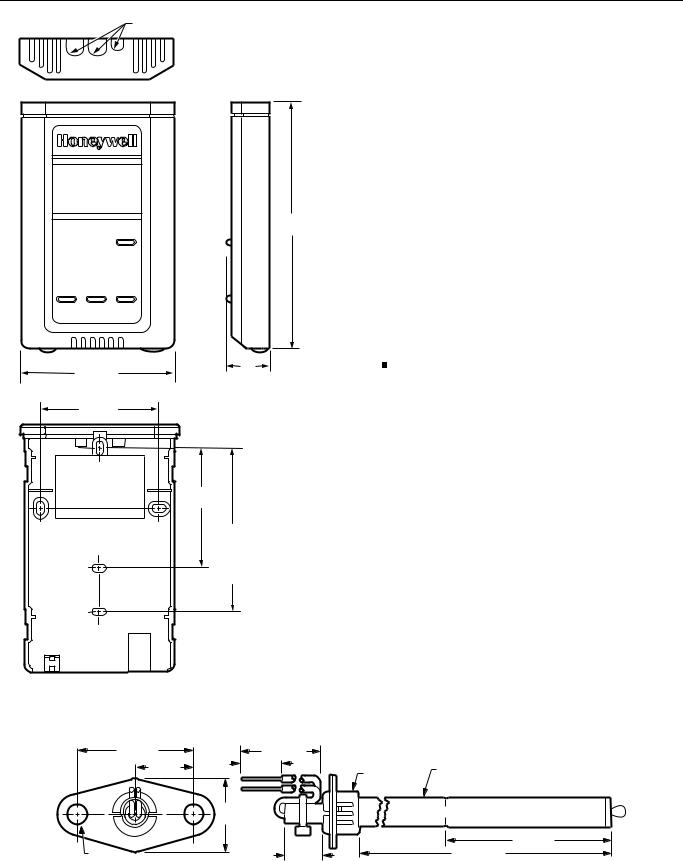
EXCEL 10 W7751B,D,F,H VAVII CONTROLLERS
KNOCKOUTS FOR EUROPEAN APPLICATIONS
6HQVRU 'XFW 0RXQW
The C7770A Air Temperature Sensor is used for duct temperature sensing with Excel 10 Controllers (see Product Names section). The C7770A Air Temperature Sensor is shown in Fig. 11.
5-1/16
(128)
3-5/32 (80) |
1 |
|
(25) |
||
|
||
2-3/8 (60) |
|
2-3/8
(60)
STANDARD
UTILITY
CONDUIT
BOX (2 BY 4)
MOUNTING
HOLES
M11751
Fig. 10. T7780 construction in in. (mm) sensor.
&RQILJXUDWLRQV
*HQHUDO
Table 4 provides an overview of the Excel 10 VAV Controller configuration options. All VAV boxes are assumed to have an air flow pickup for connecting to the Microbridge flow through pressure sensor on the Excel 10 VAV Controller. Also, each box must have a flowregulating damper that is controlled by a Series 60 (floating) type actuator such as the Honeywell ML6161 or a PWM type actuator. Table 5 lists the general mechanical equipment options available with the W7751 VAV Box Controller. See Table 1 for Excel 10 VAV Box Controller capabilities. See Application Step 6. Configure Controllers for further information on configurations.
 CAUTION
The Excel 10 VAV Controller is designed to work with Series 60 (floating) Damper Actuators that have a full stroke damper actuator time between 20 and 600 seconds (0.333 to 10 minutes) or PWM Damper Actuators that have a minimum time (zero percent) of 0.1 second and a maximum overall time of 600 seconds (0.1 second to 10 minutes).
The W7751H Excel 10 VAV Controller is designed to work only with the Series 60 (floating) Damper Actuator (ML6161B) that has a full stroke damper actuator time of 90 seconds.
1-1/2 (38) |
8-1/2 (216) |
|
|
3/4 (19) |
1/2 (13) |
3/8 IN. (10) |
|
1/2 IN. (13) |
|||
|
|||
|
DIAMETER |
DIAMETER |
|
|
7/8 |
|
|
|
(22) |
|
|
|
|
3-1/2 (89) |
|
1/4 (6) |
1/2 (13) |
6-5/32 (156) |
|
DIAMETER (2 HOLES) |
M7724 |
||
|
Fig. 11. C7770A construction - in. (mm).
23 |
74-2949–1 |

EXCEL 10 W7751B,D,F,H VAVII CONTROLLERS
Table 4. Excel 10 VAV Box Controller Capability.
Excel 10 VAV Box |
|
|
Controller Capability |
W7751B,D,F |
W7751H |
|
|
|
Fan |
|
|
|
|
|
None |
X |
X |
|
|
|
Series |
X |
X |
|
|
|
Parallel Temp |
X |
X |
|
|
|
Parallel Flow |
X |
X |
|
|
|
Parallel PWM |
X |
X |
|
|
|
Reheat |
|
|
|
|
|
None |
X |
X |
|
|
|
One Stage Reheat |
X |
X** |
|
|
|
Two Stages or Three Stage |
X |
X** |
Binary Control Reheat |
|
|
|
|
|
Three Stages Reheat |
X |
— |
|
|
|
One Stage Periph |
X |
X** |
|
|
|
Floating Reheat (Two outputs) |
X |
X** |
|
|
|
Floating Periph (Two outputs) |
X |
X** |
|
|
|
Floating Reheat then Periph |
X |
— |
(Four outputs) |
|
|
|
|
|
Floating Periph then Reheat |
X |
— |
(Four outputs) |
|
|
|
|
|
PWM Reheat (One output) |
X |
X** |
|
|
|
PWM Periph (One output) |
X |
X** |
|
|
|
PWM Reheat then Periph |
X |
X** |
(Two outputs) |
|
|
|
|
|
PWM Periph then Reheat |
X |
X** |
(Two outputs) |
|
|
|
|
|
Exhaust Tracking |
|
|
|
|
|
Disabled |
X |
X |
|
|
|
Enabled |
X |
X |
|
|
|
Occupancy Sensor |
|
|
|
|
|
None |
X |
X |
|
|
|
Connected |
X |
—* |
|
|
|
Excel 10 VAV Box |
|
|
Controller Capability |
W7751B,D,F |
W7751H |
|
|
|
Window Contact |
|
|
|
|
|
None |
X |
X |
|
|
|
Connected |
X |
—* |
|
|
|
Wall Module Configuration |
|
|
|
|
|
Local |
X |
X |
|
|
|
Shared |
X |
X |
|
|
|
Wall Module Type |
|
|
|
|
|
Sensor Only |
X |
X |
|
|
|
Sensor and Setpoint |
X |
X |
|
|
|
Sensor, Setpoint and Bypass |
X |
X |
|
|
|
Sensor and Bypass |
X |
X |
|
|
|
Air Temperature Sensor |
|
|
|
|
|
20 K ohm air temperature |
X |
X |
sensors can be used in |
|
|
conjunction with wall modules |
|
|
|
|
|
Dual Duct Pressure |
|
|
Independent |
|
|
|
|
|
Flow mixing |
X*** |
X*** |
Cold and hot duct flow |
|
|
pickups |
|
|
|
|
|
Without flow mixing |
X*** |
X*** |
Cold and hot duct flow |
|
|
pickups |
|
|
|
|
|
Constant volume |
X*** |
X*** |
Cold and hot duct flow |
|
|
pickups |
|
|
|
|
|
With cold duct pickup only |
X |
X |
|
|
|
Constant volume with |
X**** |
X**** |
discharge pickup only |
|
|
|
|
|
Dual Duct Pressure |
|
|
Dependent |
|
|
|
|
|
With flow mixing |
X |
X |
|
|
|
Without flow mixing |
X |
X |
|
|
|
*Available only via the network for the W7751H.
**The W7751H Smart VAV Actuator provides damper control and two configurable outputs available for 2 stages of reheat, floating reheat (requires two outputs), PWM Reheat or Periph (requires one output), PWM Reheat and Periph (requires two outputs) or 1 stage of reheat or Periph (an be PWM) and a serial or parallel fan.
***These applications require two W7751 Excel 10 controllers per zone.
****Flow sensor in discharge air. The temperature control loop controls the cool damper position and the flow controls adjust the heating damper position.
74-2949–1 |
24 |

EXCEL 10 W7751B,D,F,H VAVII CONTROLLERS
Table 5. Configuration Options Summary For W7751 Controllers.
|
|
Possible Configurations for the W7751B,D,F |
|
|
Option |
|
Models |
Possible Configurations for the W7751H Model |
|
|
|
|
|
|
Fan |
1. |
None |
1. |
None |
|
|
|
|
|
|
2. |
Parallel Temperature |
2. |
Parallel Temperature |
|
|
|
|
|
|
3. |
Parallel Flow |
3. |
Parallel Flow |
|
|
|
|
|
|
4. |
Parallel PWM |
4. |
Parallel PWM |
|
|
|
|
|
|
5. |
Series |
5. |
Series |
|
|
|
|
|
Type of |
1. |
One stage |
1. |
One stage |
Reheat Coil |
2. |
Two stages or Three Stage Binary |
2. Two stages or Three Stage Binary |
|
|
|
|
|
|
|
3. |
Three stages |
3. |
Series 60 Modulating electric valve, or pneumatic |
|
|
|
|
via transducer. |
|
|
|
|
|
|
4. |
Series 60 Modulating electric valve, or pneumatic |
4. |
Pulse Width Modulating electric valve, or |
|
|
via transducer. |
|
pneumatic via transducer. |
|
|
|
|
|
|
5. |
Pulse Width Modulating electric valve, or |
5. |
None |
|
|
pneumatic via transducer. |
|
|
|
|
|
|
|
|
6. |
None |
|
|
|
|
|
|
|
Type of |
1. |
One stage |
1. |
One stage |
Peripheral |
2. |
Series 60 Modulating electric valve, or pneumatic |
2. |
Series 60 Modulating electric valve, or pneumatic |
Heat* |
|
via transducer. |
|
via transducer. |
|
|
|
|
|
|
3. |
Pulse Width Modulating electric valve, or |
3. |
Pulse Width Modulating electric valve, or |
|
|
pneumatic via transducer. |
|
pneumatic via transducer. |
|
|
|
|
|
|
4. |
None |
4. |
None |
|
|
|
|
|
Window Open |
1. |
None |
1. |
None |
Option |
2. |
Local Window Open Digital Input - directly wired |
2. |
Network (DestWndw signal received via the |
|
|
to the controller. (Contacts closed means |
|
E-Bus). |
|
|
Window Closed.) |
|
|
|
|
|
|
|
|
3. |
Network (DestWndw signal received via the |
|
|
|
|
E-Bus). |
|
|
|
|
|
|
|
Monitor switch |
1. |
None |
1. |
None |
Option |
2. |
Local Monitor switch (general purpose) Digital |
|
|
|
|
Input -directly wired to the controller. (Contacts |
|
|
|
|
closed means that the switch is closed.) |
|
|
|
|
|
|
|
Occupancy |
1. |
None |
1. |
None |
Sensor Option |
2. |
Local Occupancy sensor Digital Input - directly |
2. |
Network (DestOccSensor signal received via the |
|
|
wired to the controller. (Contacts closed means |
|
E-Bus). |
|
|
occupancy sensed.) |
|
|
|
|
|
|
|
|
3. |
Network (DestOccSensor signal received via the |
|
|
|
|
E-Bus). |
|
|
|
|
|
|
|
Heat/Cool |
1. |
None |
1. |
None |
change over |
2. |
Local Heat/Cool change over switch Digital Input |
|
|
switch Option |
|
directly wired to the controller. (Contacts closed |
|
|
|
|
means select Heat Mode.) |
|
|
|
|
|
|
|
Wall Module |
1. |
Local (direct wired to the box) |
1. |
Local (direct wired to the box) |
Option |
2. |
Shared (wired to another box) |
2. |
Shared (wired to another box) |
|
|
|
|
|
Wall Module |
1. |
Sensor only |
1. |
Sensor only |
Type |
2. |
Sensor and Setpoint adjust |
2. |
Sensor and Setpoint adjust |
|
|
|
|
|
|
3. |
Sensor, Setpoint adjust and Bypass |
3. |
Sensor, Setpoint adjust and Bypass |
|
|
|
|
|
|
4. |
Sensor and Bypass |
4. |
Sensor and Bypass |
|
|
|
|
|
|
5. |
None |
5. |
None |
|
|
|
|
|
(continued)
25 |
74-2949–1 |
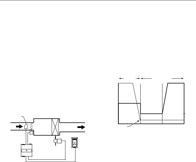
EXCEL 10 W7751B,D,F,H VAVII CONTROLLERS
Table 5. Configuration Options Summary For W7751 Controllers (Continued).
|
|
Possible Configurations for the W7751B,D,F |
|
|
Option |
|
Models |
|
Possible Configurations for the W7751H Model |
|
|
|
|
|
Air |
1. |
Discharge Air Temperature |
1. |
Discharge Air Temperature** |
Temperature |
|
|
|
|
Sensor |
|
|
|
|
|
|
|
|
|
|
2. |
Supply Air Temperature |
2. |
Supply Air Temperature** |
|
|
|
|
|
|
3. |
None |
3. |
None |
|
|
|
|
|
*If both Reheat and peripheral heat are used in the same application:
¾Both must be same output type such that both are: staged, floating or PWM
¾The first and second stage ordering is selectable between stage 1 - reheat, stage 2 peripheral or stage 1- peripheral, stage 2 reheat.
**Only 1 Analog input is configurable on the W7751H and only if the T7770A or D (no Space temperature setpoint) Wall modules are used.
7\SH RI %R[ )DQ
Each VAV box that is controlled by a W7751B,D,F,H can have a series fan (see Fig. 22), a parallel fan (see Fig. 23), or no fan (see Fig. 12).
The air temperature sensor cannot be used on the W7751H Smart VAV Actuator with wall modules that have a setpoint.
AIR FLOW |
REHEAT |
|
COIL (OPTIONAL) |
||
SENSOR |
||
|
PRIMARY
AIR
DISCHARGE
AIR
T7770
DAMPER
ACTUATOR
VALVE
W7751
CONTROLLER
M11824
Fig. 12. VAV box (without fan).
Figs. 13 through 21 illustrate the W7751B,D,F,H VAV Controllers that have a box type of (single duct) with DestHvacMode in (the default of Auto).
Refer to Fig. 13 to see VAV box modes for Pressure_Independent or (Pressure_Dependent), Reheat type Float_Reheat/Float_Periph, Non-Proportional.
Pressure Type:
Pressure Independent or (Pressure_Dependent)
Reheat Type:
Float_Reheat or Float_Periph
Proportional Reheat Flow:
Disable
Periph Min Pos:
Greater than 0%
|
REHEAT |
COOLING MODE |
|
100 |
MODE |
|
MAX |
|
|
||
PERCENT |
|
|
FLOW |
OPEN |
|
|
(POS) |
REHEAT
FLOW
MIN FLOW (POS)
Periph Min Pos |
HeatOccSpt |
CoolOccSpt |
M11826 |
Fig. 13. VAV box modes for Reheat Type Float_Reheat/Float_Periph, Non-Proportional. (suited for Peripheral heat control because the Peripheral output closes to a minimum position (Periph Min Pos) at HeatOccSpt).
Refer to Fig. 14 to see VAV box modes for Pressure_Independent or (Pressure_Dependent), Reheat type Float_Reheat/Float_Periph, Proportional.
Pressure Type:
Pressure Independent or (Pressure_Dependent)
Reheat Type:
Float_Reheat or Float_Periph
Proportional Reheat Flow:
Enable
Periph Min Pos:
Equals 0
74-2949–1 |
26 |
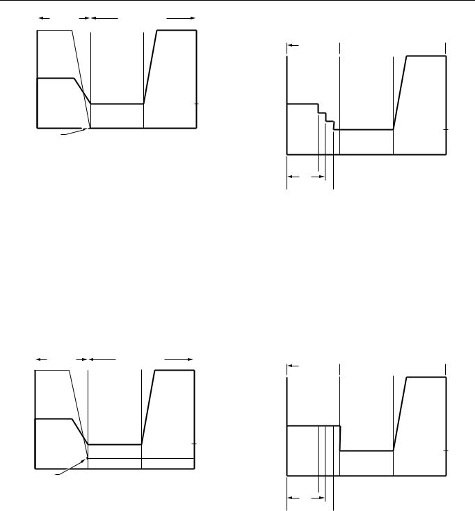
EXCEL 10 W7751B,D,F,H VAVII CONTROLLERS
|
|
REHEAT |
COOLING MODE |
|
100 |
|
MODE |
|
MAX |
|
|
|||
PERCENT |
|
|
|
|
OPEN |
|
|
|
(POS) |
REHEAT
FLOW
MIN (POS)
Periph Min Pos |
HeatOccSpt |
CoolOccSpt |
M11827 |
Fig. 14. VAV box modes for Reheat Type Float_Reheat/Float_Periph, Proportional. (suited for Reheat control because the Reheat closes to zero percent at HeatOccSpt).
Refer to Fig. 15 to see VAV box modes for Pressure_Independent or (Pressure_Dependent),Reheat type Float_Reheat/Float_Periph, Proportional.
Pressure Type:
Pressure Independent or (Pressure_Dependent)
Reheat Type:
Float_Reheat or Float_Periph
Proportional Reheat Flow:
Enable
Periph Min Pos:
Greater than 0%
|
|
REHEAT |
COOLING MODE |
|
100 |
|
MODE |
|
MAX |
|
|
|||
|
|
|
||
PERCENT |
|
FLOW |
||
OPEN |
|
(POS) |
||
REHEAT |
|
|
|
FLOW |
|
|
|
|
|
|
MIN |
|
|
|
FLOW |
|
|
|
(POS) |
Periph Min Pos |
HeatOccSpt |
CoolOccSpt |
M11828 |
Fig. 15. VAV box modes for Reheat Type Float_Reheat/Float_Periph, Proportional. (suited for Peripheral heat control because the Peripheral output closes to a minimum position (Periph Min Pos) at HeatOccSpt).
Refer to Fig. 16 to see VAV box modes for Reheat type Elec_ThreeStage - Proportional.
Pressure Type:
Pressure Independent or (Pressure_Dependent)
Reheat Type:
Elec_ThreeStage or (Elec_ThreeStageBin), (Elec_OneStage), (Elec_TwoStage)
Proportional Reheat Flow:
Enable
REHEAT 
 COOLING MODE
MODE
MAX
FLOW (POS)
REHEAT
FLOW
MIN FLOW (POS)
HeatOccSpt CoolOccSpt
STAGE 3  ON
ON 
STAGE 2 |
ON |
M11829 |
STAGE 1  ON
ON 
Fig. 16. VAV box modes for Reheat Type Elec_ThreeStage - Proportional.
Refer to Fig. 17 to see VAV box modes for Reheat type Elec_ThreeStage - Non-Proportional.
Pressure Type:
Pressure Independent or (Pressure_Dependent)
Reheat Type:
Elec_ThreeStage or (Elec_ThreeStageBin), (Elec_OneStage), (Elec_TwoStage)
Proportional Reheat Flow:
Disable
REHEAT 
 COOLING MODE
MODE
MAX
FLOW (POS)
REHEAT
FLOW
MIN FLOW (POS)
HeatOccSpt CoolOccSpt
STAGE 3  ON
ON 
STAGE 2 |
ON |
M11830 |
STAGE 1  ON
ON 
Fig. 17. VAV box modes for Reheat Type Elec_ThreeStage - Non-Proportional.
Refer to Fig. 18 to see VAV box modes for Reheat type PeriphThenReheat - Proportional.
Pressure Type:
Pressure Independent or (Pressure_Dependent)
Reheat Type:
Float_Periph_Reheat or (PWM_Periph_Reheat)
27 |
74-2949–1 |
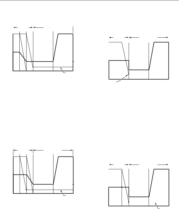
EXCEL 10 W7751B,D,F,H VAVII CONTROLLERS
Proportional Reheat Flow:
Enable
Periph Min Pos:
0% or greater
|
REHEAT |
|
||
100 |
MODE |
|
|
|
HTG |
||||
|
||||
|
|
|||
PERCENT |
|
PERIPHERAL |
||
OPEN |
REHEAT |
|
|
|
|
|
|
||
REHEAT
FLOW
MIN
FLOW
M11831 |
HeatOccSpt |
COOLING MODE 
MAX FLOW (POS)
MIN FLOW (POS)
CoolOccSpt |
Periph Min Pos |
Fig. 18. VAV box modes for Reheat type Peripheral Heating Then Reheat - Proportional (Float_Periph_Reheat/PWM_Periph_Reheatl).
Refer to Fig. 19 to see VAV box modes for Reheat type ReheatThenPeriph - Proportional.
Pressure Type:
Pressure Independent or (Pressure_Dependent)
Reheat Type:
Float_Reheat_Periph or (PWM_Reheat_Periph)
Proportional Reheat Flow:
Enable
Periph Min Pos:
0% or greater
100 PERCENT OPEN
REHEAT FLOW
MIN
FLOW
M11832
REHEAT |
COOLING MODE |
|
MODE |
|
|
HTG |
REHEAT |
MAX |
|
||
PERIPHERAL |
FLOW |
|
|
|
(POS) |
MIN FLOW (POS)
HeatOccSpt |
CoolOccSpt |
Periph Min Pos |
Fig. 19. VAV box modes for Reheat Type Reheat Then Peripheral Heating Proportional (Float_Reheat_Periph/PWM_Reheat_Periph).
Refer to Fig. 20 to see VAV box modes for Press_Dependent, Reheat type Float_Reheat/FloatHotDuctPrDep, Non-Proportional.
Pressure Type:
Pressure_Dependent
Reheat Type:
FloatHotDuctPrDep
Proportional Reheat Flow:
Disable
Periph Min Pos:
0% or greater
|
|
REHEAT |
COOLING MODE |
|
||
100 |
|
MODE |
|
|
|
MAX |
|
|
|
|
|||
|
|
|
|
|
||
PERCENT |
|
|
|
|
|
FLOW |
OPEN |
|
|
|
|
|
|
REHEAT |
|
|
|
|
|
|
FLOW |
|
|
|
|
|
|
|
|
|
|
|
|
MIN |
|
|
|
|
|
|
|
|
|
|
|
|
|
FLOW |
|
|
|
|
|
|
|
Periph Min Pos |
HeatOccSpt |
CoolOccSpt |
M11825 |
Fig. 20. VAV box modes for Reheat Type Float_Reheat/Float_Periph, no minimum position, reheat goes to zero percent in cooling mode Nonproportional (suited for Reheat control because the Reheat closes to zero percent at HeatOccSpt).
Refer to Fig. 21 to see VAV box modes for Pressure Dependent, Reheat type Float_Reheat/Float_Periph.
Pressure Type:
Pressure_Dependent
Reheat Type:
Float_Reheat/Float_Periph
Proportional Reheat Flow:
Disable
Periph Min Pos:
0% or greater
100 |
|
REHEAT |
|
COOLING MODE |
|
|
|
|
|
|
MODE |
|
|
|
|
|
MAX |
||
PERCENT |
|
|
|
|
|
|
|
|
|
|
|
|
|
|
|||||
OPEN |
|
|
|
|
|
|
|
|
FLOW |
|
|
|
|
|
|
|
|
|
(POS) |
REHEAT |
|
|
|
|
|
|
|
|
|
POS. |
|
|
|
|
|
|
|
|
|
(DAMPER) |
|
|
|
|
|
|
|
|
|
MIN |
|
|
|
|
|
|
|
|
MIN |
|
|
|
|
|
|
|
|
||
POS. |
|
|
|
|
|
|
|
|
FLOW |
M11833 |
|
|
|
|
|
|
|
|
(POS) |
|
HeatOccSpt |
CoolOccSpt |
Periph Min Pos |
||||||
|
|||||||||
|
|
||||||||
|
|
|
|
|
|
||||
Fig. 21. VAV box modes for Pressure Dependent, Reheat Type Float Reheat/Float_Periph.
74-2949–1 |
28 |
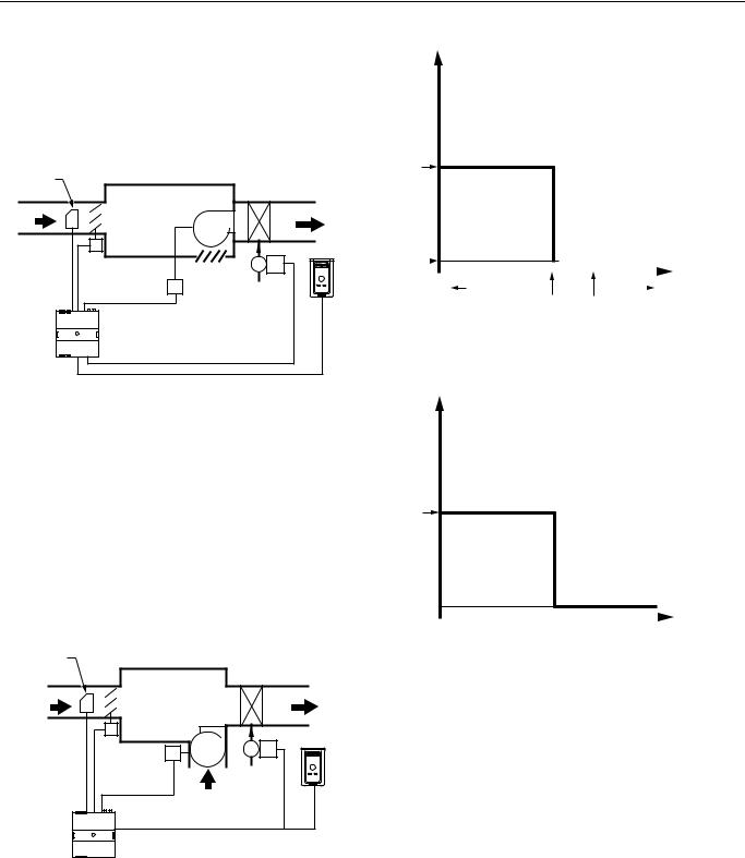
EXCEL 10 W7751B,D,F,H VAVII CONTROLLERS
A Series fan is intended to run continuously when the main air handler is on and is in-line with the primary air flow through the box. This configuration is sometimes referred to as Variable Volume Supply with Constant Volume Discharge (VVS/CVD).
NOTE: The location of the heating coils can be in the discharge, as shown in Fig. 22, or in the plenum return.
AIR FLOW |
|
SENSOR |
REHEAT |
|
|
|
COIL (OPTIONAL) |
PRIMARY |
FAN |
DISCHARGE |
|
AIR |
AIR |
T7770
DAMPER |
OPEN TO |
ACTUATOR |
|
FAN |
PLENUM |
RELAY |
VALVE |
W7751 |
|
CONTROLLER |
|
M11834
Fig. 22. Series VAV box fan.
A parallel fan, see Fig. 23, is not located in the primary air stream, but is designed to add return air from the plenum into the air stream delivered to the space. The Excel 10 VAV Controller turns on the parallel fan when the space temperature falls below Setpoint as a first stage of reheat (Parallel Temp), or if the air flow falls below a minimum air flow setpoint to maintain a minimum air flow to the space (Parallel Flow).
NOTE: The location of the heating coils can be in the discharge, as shown in Fig. 23, or as part of the plenum air return, either before or after the fan.
AIR FLOW
SENSOR
|
REHEAT |
|
COIL |
PRIMARY |
DISCHARGE |
AIR |
AIR |
|
FAN |
DAMPER |
T7770 |
|
|
ACTUATOR |
|
FAN |
VALVE |
RELAY |
|
|
RETURN AIR |
|
FROM PLENUM |
W7751 |
M11835 |
|
|
CONTROLLER |
|
Fig. 23. Parallel VAV box fan.
See Fig. 24a and 24b to see the Heat/Cool Modes for Parallel Temperature/Flow VAV box fans.
PARALLEL FAN TEMP OPERATION:
COOL/REHEAT MODES
ON
OFF |
|
|
|
|
|
ROOM |
|
|
|
|
|
|
TEMPERATURE |
COLD |
WARM |
|
|
HeatOccSpt |
CoolOccSpt |
|
M11836 |
Fig. 24a. Parallel fan temperature operation: for Cool/Reheat modes.
PARALLEL FAN FLOW OPERATION:
COOL/REHEAT MODES
ON
OFF 
|
|
SUPPLY FLOW |
FanEnableFlow |
M11879 |
|
Fig. 24b. Parallel fan flow operation: for Cool/Reheat modes.
Refer to Fig. 25 to see Dual Duct, Pressure Independent, with flow mixing that has cold and hot duct flow pickups.
29 |
74-2949–1 |

EXCEL 10 W7751B,D,F,H VAVII CONTROLLERS
FLOW HOT SENSOR DUCT
SUPPLY AIR
COLD
FLOW
DUCT
SUPPLY
AIR
SENSOR
W7751  CONTROLLER MASTER
M11837
DISCHARGE
AIR
T7770
SPACE
AIR
TEMP
W7751
CONTROLLER
SATELLITE
Fig. 25. Dual Duct, Pressure Independent, with flow mixing that has cold and hot duct flow pickups (uses a satellite Excel 10 for hot duct).
Dual Duct Flow Mixing: (For setup and Calibration refer to the Dual Duct Calibration procedure in Appendix B.)
Master flow configuration:
Master_Flow_Mix
Master reheat configuration:
DualDuctReheat
Satellite flow configuration:
Satel_Flow_Mix
Satellite reheat configuration:
DualDuctReheat
NOTE: SrcMaster from the Master Excel 10 must be bound to DestSatellite of the Satellite Excel 10 and SrcBoxFlow of the Satellite Excel 10 must be bound to DestFlowTrack of the Master Excel 10 (see Refer Excel 10 Points in Network menu in E- Vision) in order for this application to function properly.
Dual duct flow mixing uses two control devices, a master (for the cold duct) and a satellite (for the hot duct) to provide pressure independent control. If there is a need for cooling, dual duct flow mixing will control temperature to the cooling setpoint, setting the flow control setpoint for the cold duct between min flow and max flow while setting the hot duct flow setpoint to zero. If the temperature of the space is between the cooling and the heating setpoints, the cold duct will control to the min flow while the hot duct flow is set to zero. If there is a need for heating, the controllers will try to control to the heating setpoint by first modulating the cold duct flow from min flow to zero while simultaneously modulating the hot duct flow from zero to min flow. If there is additional need for heat, the hot duct will modulate from min flow to max flow while the cold duct
is set to zero. Since during the initial heating load, both the hot and cold duct are supplying air, we have flow mixing.
See Fig. 26 for Heat/Cool Modes for Dual Duct, Pressure Independent, with flow mixing, that has cold and hot duct flow pickups.
COLD DUCT
MASTER
MAX CLG FLOW SP
HOT DUCT
SATELLITE
MAX HTG FLOW SP
MIN HTG FLOW SP
MIN CLG FLOW SP
MIXING
ZONE
M11838 |
COLD |
HeatOccSpt |
CoolOccSpt |
HOT |
(THIS IS THE MIXING ZONE)
Fig. 26. Heat/Cool Modes for Dual Duct, Pressure Independent, with flow mixing, that has cold and hot duct flow pickups.
See Fig. 27 for Dual Duct, Pressure Independent, without flow mixing, that has cold and hot duct flow pickups.
FLOW HOT SENSOR DUCT
SUPPLY AIR
COLD
FLOW
DUCT
SUPPLY
AIR
SENSOR
W7751  CONTROLLER MASTER
M11837
DISCHARGE
AIR
T7770
SPACE
AIR
TEMP
W7751
CONTROLLER
SATELLITE
Fig. 27. Dual Duct, Pressure Independent, without flow mixing, that has cold and hot duct flow pickups (uses a satellite Excel 10 for hot duct).
Dual Duct No Flow Mixing: (For setup and Calibration refer to the Dual Duct Calibration procedure in Appendix B.)
Master flow configuration:
Master_No_Flow_Mix
74-2949–1 |
30 |
 Loading...