


VR8205A
VR8105, VR8205, AND VR8305 DIRECT IGNITION COMBINATION GAS CONTROLS
3 69-1226—04
Table 6. VR8205A,H/VR8305A,H CE Models.
CAUTION
Equipment Damage Hazard.
Improper use can damage equipment.
Read the instructions before use. This control
must be installed in accordance with the rules in
force.
Water or Steam Cleaning
If a control gets wet, replace it. If the appliance is likely to
be cleaned with water or steam, protect (cover) the
control and wiring from water or steam flow. Mount the
control high enough above the bottom of the cabinet so it
does not get wet during normal cleaning procedures.
High Humidity or Dripping Water
Dripping water can cause the control to fail. Never install
an appliance where water can drip on the control. In
addition, high ambient humidity can cause the control to
corrode and fail. If the appliance is in a humid
atmosphere, make sure air circulation around the control
is adequate to prevent condensation. Also, regularly
check out the system.
Corrosive Chemicals
Corrosive chemicals can attack the control, eventually
causing a failure. If chemicals are used for routine
cleaning, avoid contact with the control. Where chemicals
are suspended in air, as in some industrial or agricultural
applications, protect the control with an enclosure.
Dust or Grease Accumulation
Heavy accumulations of dust or grease can cause the
control to malfunction. Where dust or grease can be a
problem, provide covers for the control to limit
contamination.
Heat
Excessively high temperatures can damage the control.
Make sure the maximum ambient temperature at the
control does not exceed the rating of the control. If the
appliance operates at very high temperatures, use
insulation, shielding, and air circulation, as necessary, to
protect the control. Proper insulation or shielding should
be provided by the appliance manufacturer; verify proper
air circulation is maintained when the appliance is
installed.
INSTALLATION
When Installing This Product…
1. Read these instructions carefully. Failure to follow
them could damage the product or cause a
hazardous condition.
2. Check the ratings given in the instructions and on
the product to make sure the product is suitable for
your application.
3. Installer must be a trained, experienced service
technician.
4. After installation is complete, check out product
operation as provided in these instructions.
WARNING
Fire or Explosion Hazard.
Can cause severe injury, death or property
damage.
Follow these warnings exactly:
1. Disconnect power supply before wiring to
prevent electrical shock or equipment damage.
2. To avoid dangerous accumulation of fuel gas,
turn off gas supply at the appliance service
valve before starting installation, and perform
Gas Leak Test after installation is complete.
3. Always install a sediment trap in gas supply line
to prevent contamination of gas control.
4. Do not force the gas control knob. Never use
any tools. If the gas control knob does not
operate by hand, the gas control should be
replaced by a qualified service technician.
Force or attempted repair may result in fire or
explosion.
CAUTION
Equipment Damage.
Can burn out valve coil terminals.
Never apply a jumper across (or short) the valve
coil terminals, even temporarily.
Follow the appliance manufacturer instructions, if
available. Otherwise, use these instructions as a guide.
IMPORTANT
These gas controls are shipped with protective
seals over the inlet and outlet tappings. Do not
remove the seals until ready to install adapters
or connect the piping.
Specification VR8205A,H (CE Model Only) VR8305A,H (CE Model Only)
Main Valve Connection 1/2 in. ISO, 7/1 internal thread (BSP.PL) 1/2 in., 3/4 in. ISO, 7/1 internal thread
(BSP.PL).
Ambient Temperature Range -20°C to +70°C (-4°F to +158°F)
Maximum Inlet Pressure 60 mBar (24 in. wc).
Pressure Regulation Servo regulator with adjustable outlet pressure; in accordance with EN 88 Class C.
Natural gas: 9mBar, typical; LP: 20 mBar, typical.
Regulator Adjustment For natural gas, 7.5 mBar to 12.5 mBar, field adjustable.
For LP gas, 20 mBar to 30 mBar, field adjustable.
Ground Terminal 6.3 mm
Pressure Taps 9 mm OD
Valve Classification B+D C+D
VR8105, VR8205, AND VR8305 DIRECT IGNITION COMBINATION GAS CONTROLS
69-1226—04 4
Converting Gas Control from Natural GAs
to LP Gas (or LP Gas to Natural Gas)
WARNING
Fire or Explosion Hazard.
Can cause severe injury, death or property
damage.
1. Do not attempt to convert step-opening models
(suffix letter P).
2. Always change the main and pilot burner
orifices when converting from natural to LP gas
or from LP to natural gas. Carefully follow
appliance manufacturer specification and
instructions to assure proper appliance
conversion.
3. Gas controls are factory-set for natural (and
manufactured) gas or LP gas. Do not attempt to
use a gas control set for natural (manufactured)
gas on LP gas or a gas control set for LP gas
on natural (manufactured) gas.
Controls with standard, slow-opening, and two-stage
regulators (model numbers with suffix letters H, K, M, or
Q) can be converted from one gas to the other with a
conversion kit (ordered separately). See Table 4 for the
correct conversion kit.
Convertible Pressure Regulators
Controls with suffix letter R are convertible pressure
regulator models. They can be converted from natural gas
to LP gas or from LP gas to natural gas without a
conversion kit.
Before converting the control from one gas to the other,
check the control label and the appliance manufacturer
rating plate to determine of the pressure regulator setting
(factory-set) will meet the appliance manifold
requirements after conversion.
NOTE: Convertible pressure regulator models (suffix
letter R) do not have field-adjustable regulators.
If the factory pressure regulator setting meets the
appliance manifold requirement, convert the control as
follows:
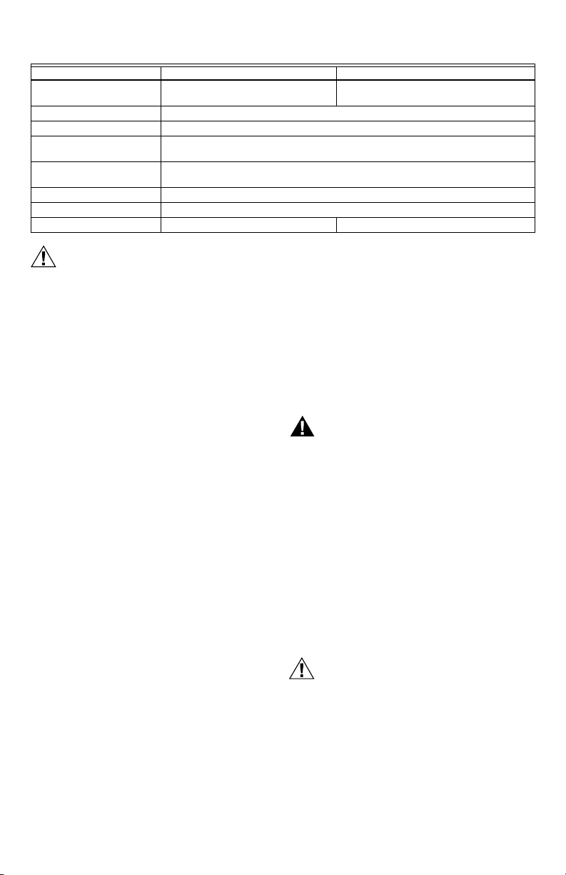
1. Remove the pressure regulator cap, Fig. 1.
2. Invert the cap so that the letters appear that
represent the gas type appropriate for the
appliance; NAT for natural (manufactured) gas, LP
for liquid petroleum gas.
3. Replace the cap and tighten firmly.
Fig. 1. Top view of convertible pressure regulator cap.
Install Adapters to Control
If adapters are being installed on the control, mount them
as follows:
Flanges
1. Choose the appropriate flange for your application.
Remove the seal over the ignition system control inlet or
outlet.
2. Make sure the O-ring is fitted in the groove of the
flange. If the O-ring is not attached or is missing, do
not use the flange.
3. With the O-ring facing the gas control, align the
screw holes on the control with the holes in the
flange.
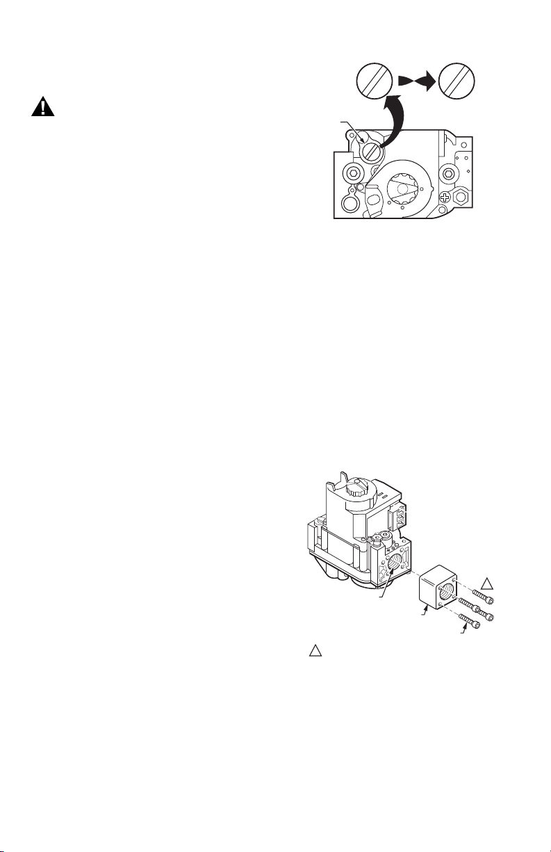
4. Insert and tighten the screws provided with the
flange. See Fig. 2. Tighten the screws to 25 inch-
pounds of torque to provide a gas-tight seal.
Fig. 2. Firmly fasten flange to valve,
but do not overtighten screws.
Bushings
1. Remove the seal over the control inlet or outlet.
2. Apply a moderate amount of good quality pipe
compound to the bushing, leaving two end threads
bare. On an LP installation, use compound that is
resistant to LP gas. Do not use Teflon® tape.
3. Insert the bushing in the control and carefully thread
the pipe into the bushing until tight.
PRESSURE
REGULATOR
CAP
M11678
N
A
T
N
A
T
L
P
L
P
N
A
T
N
A
T
OR
OTHER SIDE
OF CAP
M9046
VALVE OUTLET
FLANGE
9/64 INCH HEX SCREWS (4)
DO NOT OVERTIGHTEN SCREWS. TIGHTEN TO
25 INCH-POUNDS.
1
1

VR8105, VR8205, AND VR8305 DIRECT IGNITION COMBINATION GAS CONTROLS
5 69-1226—04
Complete the instructions below for installing the piping,
installing the control, connecting the pilot gas tubing and
the wiring. Make sure the leak test you perform on the
control after completing the installation includes leak
testing the adapters and screws. If you use a wrench on
the valve after the flanges are installed, use the wrench
only on the flange, not on the control. See Fig. 5.
Location
The gas controls are mounted in the appliance vestibule
on the gas manifold. If this is a replacement application,
mount the gas control in the same location as the old
control.
Locate the combination gas control where it cannot be
affected by steam cleaning, high humidity, or dripping
water, corrosive chemicals, dust or grease accumulation
or excessive heat. To assure proper operation, follow
these guidelines:
• Locate gas control in a well-ventilated area.
• Mount gas control high enough above cabinet bottom
to avoid exposure to flooding or splashing water.
• Assure the ambient temperature does not exceed the
ambient temperature rating for each component.
• Cover gas control if appliance is cleaned with water,
steam or chemicals or to avoid dust and grease
accumulation.
• Avoid locating gas control where exposure to corrosive
chemical fumes or dripping water is likely.
Install Piping to Control
All piping must comply with local codes and ordinances or
with the National Fuel Gas Code (ANSI Z223.1, NPFA No.
54), whichever applies. Tubing installation must comply
with approved standards and practices.
1. Use new, properly reamed pipe that is free from
chips. If tubing is used, make sure the ends are
square, deburred and clean. All tubing bends must
be smooth and without deformation.
2. Run pipe or tubing to the control. If tubing is used,
obtain a tube-to-pipe coupling to connect the tubing
to the control.
3. Install a sediment trap in the supply line to the
control. See Fig. 3.
Install Control
1. Mounted 0 to 90 degrees in any direction, including
vertically, from the upright position of the gas control
knob.
2. Mount so the gas flow is in the direction of the arrow
on the bottom of the control.
3. Thread the pipe the amount shown in Table 7 for
insertion into control or adapters. Do not thread
pipe too far. Valve distortion or malfunction can
result if the pipe is inserted too deeply.
Table 7. NPT Pipe Thread Length (in.).
Fig. 3. Sediment trap installation.
4. Apply a moderate amount of good quality pipe com-
pound (do not use Teflon® tape) only to the pipe,
leaving two end threads bare. On LP installations,
use a compound resistant to LP gas. See Fig. 4.
5. Remove the seals over the control inlet and outlet if
necessary.
6. Connect the pipe to the control inlet and outlet. use
a wrench on the square ends of the control. If a
flange is used, place the wrench on the flange
rather than on the control. Refer to Fig. 5 and 6.
Fig. 4. Use moderate amount of pipe compound.
Pipe
Size
Thread Pipe
this Amount
Maximum Depth Pipe can be
inserted into Control
3/8 9/16 3/8
1/2 3/4 1/2
3/4 13/16 3/4
GAS
CONTROL
GAS
CONTROL
HORIZONTAL
DROP
PIPED
GAS
SUPPLY
PIPED
GAS
SUPPLY
3 IN.
(76 MM)
MINIMUM
3 IN.
(76 MM)
MINIMUM
RISER
GAS
CONTROL
TUBING
GAS
SUPPLY
HORIZONTAL
DROP
3 IN.
(76 MM)
MINIMUM
RISER
M3077
2
1
2
2
1
2
ALL BENDS IN METALLIC TUBING SHOULD BE SMOOTH.
CAUTION: SHUT OFF THE MAIN GAS SUPPLY BEFORE REMOVING
END CAP TO PREVENT GAS FROM FILLING THE WORK AREA. TEST
FOR GAS LEAKAGE WHEN INSTALLATION IS COMPLETE.
TWO IMPERFECT
THREADS
GAS CONTROL
THREAD PIPE THE AMOUNT
SHOWN IN TABLE FOR
INSERTION INTO GAS CONTROL
APPLY A MODERATE AMOUNT OF
PIPE COMPOUND TO PIPE ONLY
(LEAVE TWO END THREADS BARE).
M3075B
PIPE
 Loading...