


V5032 Kombi-2-plus
BALANCING AND SHUTOFF VALVE
PRODUCT DATA
Design |
The Kombi-2-plus valve consists of:
•Valve body with pressure test cocks and internal threads DN10...DN20 to DIN2999 (ISO7) for threaded pipe or copper and precision steel pipe 10...20 mm (see Accessories), or
•Valve body DN25...DN80 with pressure test cocks and internal threads to DIN2999 (ISO7) for threaded pipe
•Valve insert
•Blue handwheel with pre-setting dial and display
Materials
•Valve housing made of red bronze
•Valve insert and pressure test cocks made of brass
•O-rings and soft seals made of EPDM
•Handwheel, pre-setting dial and display made of plastic
CONTENTS |
|
Design ................................................................................... |
1 |
Materials................................................................................ |
1 |
Application............................................................................ |
1 |
Features ................................................................................ |
1 |
Specifications....................................................................... |
2 |
Function................................................................................ |
2 |
Dimensions, kvs-values and Ordering Information .......... |
2 |
Accessories.......................................................................... |
3 |
Connections ....................................................................... |
3 |
Accessories........................................................................ |
3 |
Measuring equipment......................................................... |
3 |
Spare parts......................................................................... |
3 |
Flow Data .................................................................... |
4 to 11 |
Influence of Coolants on Flow Values.............................. |
12 |
Correction Factor f ........................................................... |
12 |
Application
The Kombi-2-plus is installed in the return mains of pump driven warm water heating systems and cold water cooling systems to regulate the hydronic balance and as shutoff valve. The Kombi-2-plus has an O-ring spindle seal and is maintenance free. The valve body can be insulated easily and is equipped with pressure test cocks for differential pressure or flow measurement.
Further functions can be retrofitted without interrupting operation of the system: draining, filling and automatic regulation (in combination with a Kombi-3-plus BLACK valve in the supply and a Kombi-Diaphragm Unit).
Features
•Maintenance free spindle with double O-ring sealings
•PTFE seat sealing
•High accuracy of the pre-setting because of individual adjustment
•Valve body PN16
•Dimensions DN15 to DN40 can be retrofitted with a Kombi-Diaphragm Unit
•Robust valve body made of corrosion resistant red bronze
•Availabe in sizes up to DN80
•Visible pre-setting dial with concealed pre-setting wheel
Copyright © 2002 Honeywell AG • All rights reserved |
EN0H-0048GE25 R0402 |
KOMBI-2-PLUS (V5032)
Specifications
Medium |
Water, water-glycole mixture |
Operating temperature |
2...130°C (36...266°F) |
Operating pressure |
max. 16 bar (232 psi) |
Differential pressure |
max. 2,0 bar (29 psi) – |
|
see NOTE below |
kvs (cv)-values |
see table on page 2 |
NOTE: Differential pressure: Closing pressure for Kombi-2-plus with installed Kombi-Diaphragm Unit. Regarding noise generation the conditions, requirements and installation design have to be taken into account.
Function
The hydronic balance is a significant requirement for the efficient operation of a hydronic heating or cooling installation. In an unbalanced system under or over provision of hot water to individual radiators or circuits can occur. Apart from the correct selection of radiator valves, regulation of individual circuits is also necessary and in some cases, such as in
DIN 18 380, VOB part C, is required by national standards.
This requirement is met with the shutoff and balancing valve Kombi-2-plus. The Kombi-2-plus for the return has the functions shutoff, pre-setting, regulation (with diaphragm unit, accessory), draining and filling (draining adapter, accessory).
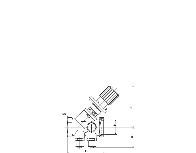
Dimensions, kvs-values and Ordering Information
Type |
DN |
kvs (cv)- |
|
|
Dimensions |
|
|
OS-No. |
|||
|
|
value |
D |
H |
|
L1 |
|
L2 |
SW |
|
|
Internal threads |
15 |
2,7 |
(3,16) |
Rp1/2” |
85 |
|
65 |
|
41 |
27 |
V5032Y0015 |
|
|
|
|
|
|
|
|
|
|
|
|
Internal threads |
20 |
6,4 |
(7,49) |
Rp3/4” |
100 |
|
75 |
|
42 |
32 |
V5032Y0015 |
|
|
|
|
|
|
|
|
|
|
|
|
Internal threads |
25 |
6,8 |
(7,96) |
Rp1” |
100 |
|
90 |
|
45 |
41 |
V5032Y0015 |
Internal threads |
32 |
21,0 |
(24,6) |
Rp1 1/4” |
137 |
|
110 |
|
46 |
50 |
V5032Y0015 |
Internal threads |
40 |
22,0 |
(25,7) |
Rp1 1/2” |
137 |
|
120 |
|
49 |
55 |
V5032Y0015 |
Internal threads |
50 |
38,0 |
(44,5) |
Rp2” |
158 |
|
150 |
|
55 |
70 |
V5032Y0015 |
|
|
|
|
|
|
|
|
|
|
|
|
Internal threads |
65 |
47,7 |
(55,8) |
Rp2 1/2” |
195 |
|
180 |
|
68 |
85 |
V5032Y0015 |
|
|
|
|
|
|
|
|
|
|
|
|
Internal threads |
80 |
71,0 |
(83,1) |
Rp3” |
210 |
|
200 |
|
75 |
100 |
V5032Y0015 |
NOTE: All values in mm if not stated otherwise.
Dimension ‘H’ refers to fully open valve.
EN0H-0048GE25 R0402 |
2 |
Honeywell AG • All rights reserved |

KOMBI-2-PLUS (V5032)
Accessories
Connections
Set of compression ring and nut
1/2” x 10 mm |
VA650A1210 |
1/2” x 12 mm |
VA650A1212 |
1/2” x 14 mm |
VA650A1214 |
1/2” x 15 mm |
VA650A1215 |
1/2” x 16 mm |
VA650A1216 |
3/4” x 18 mm |
VA650A2018 |
3/4” x 22 mm |
VA650A2022 |
NOTE: Support inserts have to be used for soft copper and steel pipe (wall thickness 1 mm).
Set of compression ring, nut and support insert (2 pcs each)
1/2” x 12 mm |
VA651A1212 |
1/2” x 15 mm |
VA651A1215 |
1/2” x 16 mm |
VA651A1216 |
3/4” x 18 mm |
VA651A2018 |
Accessories
Kombi-DU Diaphragm Unit (V5012) for valves DN15...DN40
Setting range 0,1...0,3 bar |
V5012A0103 |
(1,45...4,35 psi) differential |
|
pressure |
|
Setting range 0,3...0,6 bar |
V5012A0306 |
(4,35...8,7 psi) differential |
|
pressure |
|
NOTE: For product information and diagrams see product data sheet ‘V5012 Kombi-DU’.
The Kombi-2-plus valve must be pre-set to 1.5 (for DN15...25) or 1.0 (DN32...40) when used with the Kombi-Diaphragm Unit.
Pump pressure: max. 2 bar (29 psi)
Kombi-3-plus BLACK (V5100) as shutoff valve and Kombi-DU connection point in the supply
DN15 |
|
V5100Y0015 |
DN20 |
|
V5100Y0020 |
DN25 |
|
V5100Y0025 |
DN32 |
|
V5100Y0032 |
DN40 |
|
V5100Y0040 |
Tamper-proof cap |
|
|
for valves DN15... |
DN25 |
VA2501A010 |
for valves DN32... |
DN50 |
VA2501A032 |
Adapter for actuators with M 30 x 1,5 connection |
|
for valves DN15...DN40 |
VA2500A001 |
kvs-values for Kombi-2-plus with installed adapter:
DN |
15 |
20 |
25 |
32 |
40 |
kvs-value |
1,50 |
3,50 |
3,50 |
5,50 |
5,50 |
cv-value |
1,76 |
4,1 |
4,1 |
6,44 |
6,44 |
NOTE: The Kombi-2-plus valve must be pre-set to 1.5 (for DN15...25) or 1.0 (DN32...40) when used with actuator.
Pump pressure: max. 2 bar (29 psi)
Draining adapter
for all sizes |
VA3500A001 |
Measuring equipment
Extension piece for pressure test cocks, length 45 mm – for use with insulated Kombi-2-plus
for all sizes |
VA2601A008 |
Measuring adapters (2 pcs) |
|
for all sizes |
VS3600A008 |
Flow meter |
|
for all sizes |
VM200A1001 |
‘BasicMES’ handheld measuring computer
for all sizes; computer is supVM241A1002
plied with case and accessories
Spare parts
Pressure test cocks (2 pcs)
for all sizes |
VA2600A008 |
Honeywell AG • All rights reserved |
3 |
EN0H-0048GE25 R0402 |

KOMBI-2-PLUS (V5032)
Flow Data DN15
|
|
|
|
|
|
|
|
|
|
|
|
|
|
|
Pre-setting |
|
|
|
|
|
|
8,7 |
||
|
|
|
|
|
|
|
|
|
|
|
0,3 |
0,6 0,8 1 |
1,5 |
2 2,5 |
3 |
3,5 |
4 |
4,9 |
6 |
|
||||
|
|
|
|
|
|
|
|
|
|
|
|
|
|
|
|
|
|
|
|
|
|
|
|
8 |
|
|
|
|
|
|
|
|
|
|
|
|
|
|
|
|
|
|
|
|
|
5 |
|
7 |
|
|
|
|
|
|
|
|
|
|
|
|
|
|
|
|
|
|
|
|
|
|
4 |
|
6,0 |
|
|
|
|
|
|
|
|
|
|
|
|
|
|
|
|
|
|
|
|
|
|
|
|
||
|
|
|
|
|
|
|
|
|
|
|
|
|
|
|
|
|
|
|
|
|
|
|
|
5,0 |
|
|
|
|
|
|
|
|
|
|
|
|
|
|
|
|
|
|
|
|
|
3 |
|
4,0 |
|
|
|
|
|
|
|
|
|
|
|
|
|
|
|
|
|
|
|
|
|
|
2 |
|
3,0 |
|
|
|
|
|
|
|
|
|
|
|
|
|
|
|
|
|
|
|
|
|
|
|
|
|
2,0 |
|
|
|
|
|
|
|
|
|
|
|
|
|
|
|
|
|
|
|
|
|
100 |
10000 |
|
|
|
|
|
|
|
|
|
|
|
|
|
|
|
|
|
|
|
|
|
|
|
9 |
|
|
|
|
|
|
|
|
|
|
|
|
|
|
|
|
|
|
|
|
|
|
|
|
8 |
|
|
|
|
|
|
|
|
|
|
|
|
|
|
|
|
|
|
|
|
|
|
|
|
7 |
|
1,0 |
|
|
|
|
|
|
|
|
|
|
|
|
|
|
|
|
|
|
|
|
|
|
6 |
|
|
|
|
|
|
|
|
|
|
|
|
|
|
|
|
|
|
|
|
|
|
|
|
5 |
|
|
|
|
|
|
|
|
|
|
|
|
|
|
|
|
|
|
|
|
|
|
|
|
4 |
|
|
|
|
|
|
|
|
|
|
|
|
|
|
|
|
|
|
|
|
|
|
|
|
|
|
|
0,5 |
|
|
|
|
|
|
|
|
|
|
|
|
|
|
|
|
|
|
|
|
|
3 |
|
|
|
|
|
|
|
|
|
|
|
|
|
|
|
|
|
|
|
|
|
|
|
|
2 |
|
0,3 |
|
|
|
|
|
|
|
|
|
|
|
|
|
|
|
|
|
|
|
|
|
|
|
|
||
|
|
|
|
|
|
|
|
|
|
|
|
|
|
|
|
|
|
|
|
|
mbar |
Pa |
drop |
P.S.I. |
|
|
|
|
|
|
|
|
|
|
|
|
|
|
|
|
|
|
|
|
|
10 |
1000 |
Pressure |
0,145 |
10 |
kg/h |
2 |
3 |
4 |
5 |
6 |
7 |
8 |
9 100 |
2 |
3 |
4 |
5 |
6 |
7 |
8 9 |
1000 |
|
2 |
3 |
|
|
|
|
Flow |
|
|
|
|
|
|
|
|
|
|
|
|
|
|
|
|
|
|
|
|
|
|
|
|
0,0028 l/sec |
|
|
0,01 |
|
|
|
|
0,025 |
0,05 |
|
0,1 |
|
|
|
0,25 |
|
|
0,5 |
|
|
|
|
||
Pre-setting |
0,3 |
0,4 |
0,6 |
0,8 |
1,0 |
1,2 |
1,4 |
1,6 |
1,8 |
2,0 |
2,2 |
2,4 |
2,6 |
2,8 |
3,0 |
3,2 |
3,4 |
3,6 |
kv-value |
0,37 |
0,43 |
0,49 |
0,57 |
0,65 |
0,73 |
0,81 |
0,88 |
0,94 |
1,00 |
1,05 |
1,10 |
1,16 |
1,22 |
1,32 |
1,42 |
1,57 |
1,74 |
cv-value |
0,43 |
0,50 |
0,57 |
0,67 |
0,76 |
0,85 |
0,95 |
1,03 |
1,10 |
1,17 |
1,23 |
1,29 |
1,36 |
1,43 |
1,54 |
1,66 |
1,84 |
2,04 |
|
|
|
|
|
|
|
|
|
|
|
|
|
|
|
|
|
|
|
Pre-setting |
3,8 |
4,0 |
4,2 |
4,4 |
4,6 |
4,8 |
4,9 = open |
|
|
|
|
|
|
|
|
|
|
|
kv-value |
1,92 |
2,12 |
2,31 |
2,49 |
2,63 |
2,67 |
kvs = 2,70 |
|
|
|
|
|
|
|
|
|
|
|
cv-value |
2,25 |
2,48 |
2,70 |
2,91 |
3,08 |
3,12 |
3,16 |
|
|
|
|
|
|
|
|
|
|
|
|
|
|
|
|
|
|
|
|
|
|
|
|
|
|
|
|
|
|
NOTE: Flow diagram is ONLY valid for valve WITHOUT installed actuator (-adapter) or Kombi-Diaphragm Unit
EN0H-0048GE25 R0402 |
4 |
Honeywell AG • All rights reserved |
 Loading...