


([FHO
: % ' ) 9$9 &RQWUROOHUV
%()25( ,167$//$7,21
The Excel 10 VAV Controller is a Free Topology Transceiver (FTT) LonMark® compliant device that is available in three versions: See Fig. 1.
1.W7751B—OEM Snaptrack-Mount, reference part number 207912. Use a 3-1/4 inch by 9 inch (82 mm by 228 mm) section for each installation.
2.W7751D—Internally Wired Subbase mounts on a standard four by four, a standard five by five conduit box or on DIN Rail 1-3/8 by 9/32 (35 mm by 7.5 mm) EN 50 022.
3.W7751F—Externally Wired Subbase, can be mounted
in a ring cabinet or on DIN Rail 1-3/8 by 9/32 (35 mm by 7.5 mm) EN 50 022.
The models all contain a Microbridge air flow sensor and communicate via the 78 Kilobaud Echelon® LonWorks® E-Bus Network. They differ only in mounting and terminations.
Any hardware that will be driven by the Triac outputs must have a minimum current draw, when energized, of 25 mA at 20 Vac, a maximum of 500 mA at 30 Vac for the W7751B and 1 A at 30 Vac for the W7751D,F.
3-1/4 IN. (82 MM) SNAPTRACK 
|
P1 |
P2 |
|
|
+ |
– |
P |
,167$//$7,21
Mount the VAV controllers in locations that allow clearance for wiring, servicing and module removal. (See Fig. 3 and 4 for mounting options used with the W7751D,F Subbase and Fig. 5 for mounting dimensions.)
: %
The W7751B OEM model is implemented on a snaptrack compatible printed wiring board (PWB). Terminal blocks are used to make connections to the digital input terminals (13 through 17) the wall module terminals (19 through 25), and the communications terminals 29 and 30. Connection for to access the E-Bus is provided by plugging the connector into the communications jack. Digital outputs, earth ground and 24 Vac power connections are made with quarter inch (6.35 mm) quick connects.
Mount the VAV controller onto the snaptrack. Attach all wiring to the appropriate quarter inch (6.35 mm) quick connects and terminal blocks. See Wiring section.
W7751B |
W7751D |
W7751F |
M12605
®U.S. Registered Trademark
Copyright © 1997 Honeywell Inc. ∙ All Rights Reserved
957504

EXCEL 10 W7751B,D,F VAV CONTROLLERS
: '
The W7751D uses a two-piece construction controller module and an internally wired subbase. Remove the controller module from the subbase (see Fig. 2). Field wiring 14 to 22 AWG (2.0 to 0.34 mm2) comes through a conduit into the four by four or five by five conduit box and is connected to the terminal blocks on the subbase. When wiring is complete, the controller module activates by plugging into the subbase.
The internally wired subbase either mounts on a standard 4 inch by 4 inch electrical junction box or a standard 5 inch by 5 inch electrical junction box using No. 6 (3.5 mm) screws. See Fig. 3. Attach all wiring to the appropriate terminal blocks on the subbase. See Wiring section. After checking out all wiring, plug the controller module into the subbase. Wiring checkout and troubleshooting can also be performed with the controller module installed, by placing a probe through the slots in the subbase.
: )
The W7751F uses a two-piece construction controller module and an externally wired subbase. Remove the controller module from the subbase (see Fig. 2). This subbase either mounts into a panel with screws or snaps onto standard EN 50 022 DIN rail 35 mm by 7.5 mm
(1-3/8 in. by 5/16 in.). See Fig. 4. DIN rail is available through local suppliers. Mount the subbase to the appropriate surface. Type of screws (sheet metal, self-tapping or thread forming) and length is determined by the type of mounting material at the job site. Field wiring 14 to 22 AWG (2.0 to 0.34 mm2) is connected to the terminal blocks on the top and bottom external edges of the subbase. When wiring is complete, the controller module activates by plugging into the subbase.
Attach all wiring to the appropriate terminal blocks on the externally wired subbase. See Wiring section. After checking out all wiring, plug the controller module into the subbase.
M8359
Fig. 2. W7751D,F controller module removal/replacement (W7751D shown).
NO. 6 (3.5 MM)
SCREW (4)
 DIN RAIL
NO. 6 (3.5 MM) SCREW (4)
M8360
Fig. 3. W7751D Subbase four by four or five by five conduit box mounting options (proper orientation is vertical with terminals at top and bottom as shown).
DIN RAIL RELEASES |
M12602 |
Fig. 4. W7751F Subbase wall and DIN rail mounting options (proper orientation is vertical with terminals at top and bottom as shown).
95-7504 |
2 |

EXCEL 10 W7751B,D,F VAV CONTROLLERS
MAINTAIN A MINIMUM DISTANCE |
|
|
|
|
||||||||
OF 4 IN. (100 mm) FROM OTHER |
1-3/32 |
|
4 X 4 |
|||||||||
DEVICES OR PANELS FOR |
|
|||||||||||
ATTACHING AIR FLOW TUBING. |
(28) |
|
MOUNTING |
|||||||||
|
|
|
|
|
|
|
|
|
|
|
|
HOLES |
|
|
|
|
|
|
|
|
|
|
|
|
|
|
|
|
|
|
|
|
|
|
|
|
|
|
|
|
|
|
|
|
|
|
|
|
|
|
|
|
|
|
|
|
|
|
|
|
|
|
|
|
|
|
|
|
|
|
|
|
|
|
|
|
|
|
|
|
5 X 5 |
|
|
|
1-3/8 |
MOUNTING |
|
|
5-21/32 |
(35) |
HOLES |
|
|
DIN RAIL |
|
|
|
|
(144) |
|
|
|
|
MOUNTING |
|
||
|
|
|
||
|
|
SLOT |
|
|
|
|
|
1-1/2 |
|
|
|
|
(38) |
|
5-21/32 (144) |
|
2-11/32 (60) |
1/2 |
4-21/32 (118) |
|
|
|
(13) |
|
MAINTAIN A MINIMUM DISTANCE
OF 3 IN. (76 mm) FROM OTHER
DEVICES OR PANELS FOR ACCESS
TO THE COMMUNICATIONS JACK.
Fig. 5. W7751D,F Subbase mounting dimensions (W7751D shown).

 3/4
3/4  (19)
(19)
3-7/16
(87)
1-3/32
(28)
M12603
3LSLQJ
$LU IORZ 3LFNXS
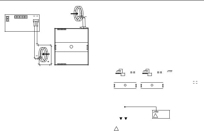
Connect the air flow pickup to the two connectors on the VAV controller. See Fig. 6.
NOTES:
—Use 1/4 inch (6 mm) outside diameter with 0.040 in. (1 mm) wall thickness plenum rated 1219 FR (94V-2) tubing.
—Always use a fresh cut on the end of the tubing that connects to the air flow pickups and the connectors on the VAV controllers.
Connect the high pressure or upstream tube to the plastic restrictor labeled (+) or P1 and the low pressure or downstream tube to the restrictor labeled (-) or P2. See labeling in Fig. 6.
NOTE: If controllers are mounted in unusually dusty or dirty environments, a 5-micron disposable air filter is recommended for the high pressure line (marked as +) connected to the air flow pickup. This applies to all controller models.
When twin tubing is used from the pickup, split the pickup tubing a short length to accommodate the connections.
NOTES:
—The tubing from the air flow pickup to the VAV controller should not exceed three feet (0.914m). Any length greater than this will degrade the flow sensing accuracy.
—Use caution when removing tubing from a VAV connector. Always pull straight away from the connector; never remove by pulling at an angle.
:LULQJ
All wiring must comply with applicable electrical codes and ordinances or as specified on installation wiring diagrams.
NOTES:
—For multiple controllers operating from a single transformer, the same side of the transformer secondary must be connected to the same input terminal in each controller and the ground terminals (28 on the W7751B, and 32 on the W7751D,F) must be connected to a verified earth ground for each controller in the group. See Fig. 7. (Controller configurations will not necessarily be limited to three devices, but the total power draw including accessories can not exceed 100 VA when powered by the same transformer (U.S. only). See System Engineering form, 74-2949, for power wiring recommendations.)
—The following pairs of terminals are electrically equivalent for 24 Vac power wiring:
W7751D,F terminals 1 and 3, 2 and 4.
—All loads on an Excel 10 controller must be powered by the same transformer that powers the Excel 10 controller.
—Keep the earth ground connection (terminal 28 on the W7751B, and terminal 32 on the W7751D,F) wire run as short as possible. Refer to Fig. 11 and 17.
—Do not connect the Analog ground nor Digital ground terminals (13, 16, 22 and 24 on the W7751B and 13, 18, 26, 28 and 31 on the W7751D,F) to earth ground. Refer to Fig. 11 and 17.
3 |
95-7504 |
EXCEL 10 W7751B,D,F VAV CONTROLLERS
AIR FLOW
PICKUP
P2 P1
W7751D,F HI LOW
W7751B
|
AIR FLOW |
M12604 |
PICKUP |
Fig. 6. VAV air flow pickup connections.
3RZHU
The 24 Vac power from an energy limited Class II Power Source must be provided to each VAV controller. To conform to Class II restrictions, transformers must not be larger than 100 VA (U.S. only). A transformer that meets CE mark requirements and that meets the Low Voltage Directive (LVD) requirements must be used in Europe for all installations of this product.
IMPORTANT
Power must be off prior to connecting to or removing connections from terminals 9 and 10 on the W7751B and terminals 1 and 2 or 3 and 4 on the W7751D,F.
Use the heaviest gauge wire available, up to 14 AWG (2.0 mm2) with a minimum of 18 AWG (1.0 mm2) for all
power and earth ground wiring. For nonplenum, open areas, run cables exposed (or in conduit if required).
See the following IMPORTANT on Heating and Cooling Equipment (UL 1995, U.S. only).
IMPORTANT
If the W7750 Controller is used on Heating and Cooling Equipment (UL 1995, U.S. only) and the transformer primary power is more than 150 volts, connect the transformer secondary to earth ground, see Fig. 7.
NOTES:
—Unswitched 24 Vac power wiring can be run in the same conduit as the E-Bus cable.
—Maintain a three-inch (76 mm) separation between Triac outputs and E-Bus wiring throughout installation.
&RPPXQLFDWLRQV
Refer to E-Bus Wiring Guidelines form, 74-2865, for a complete description of E-Bus network topology rules. Approved cable types for E-Bus communications wiring are Level IV 22 AWG (0.34 mm2) plenum or non-plenum rated unshielded, twisted pair, solid conductor wire. For nonplenum areas, U.S. part AK3781 (one pair) or U.S. part AK3782 (two pair) can be used. In plenum areas, U.S. part
AK3791 (one pair) or U.S. part AK3792 (two pair) can be used. Communications wiring can be run in a conduit, if needed, with non-switched 24 Vac or sensor wiring. If a longer E-Bus network is required, a Q7740A 2-way or Q7740B 4-way repeater can be added to extend the length of the E-Bus. A Q7751A Router can be added to partition the system into two segments and effectively double the length of the E-Bus. Only one router is allowed with each Excel 10 Zone Manager, and each network segment can have a maximum of one repeater.
Pull the cable to each controller on the E-Bus and connect to communication terminals 29 and 30 (W7751B), 19 and 20 (W7751D,F).
EARTH |
|
|
|
|
EARTH |
|
|
|
|
EARTH |
|
|
|
|
|
|
|
|
|
|
|
|
|
||||||||||||||||||||
GROUND |
GROUND |
|
|
|
|
GROUND |
|
|
|
|
|
|
|
|
|
|
|||||||||||||||||||||||||||
|
|
|
|
|
|
|
W7751D,F |
|
|
|
|
|
|
|
|
W7751D,F |
|
|
|
|
|
|
|
|
|
|
|
|
|
|
|
|
|
|
|||||||||
|
|
|
|
|
|
|
|
|
|
|
|
|
|
|
|
|
|
|
|
|
|
|
|
|
|
|
|
||||||||||||||||
|
|
|
|
|
|
|
|
|
|
|
|
|
|
|
|
|
|
|
|
|
|
|
|
|
|
|
|
|
|
|
|
|
|
|
|
|
|
|
|
|
|
|
|
|
|
|
|
32 |
|
|
|
|
|
|
|
|
|
|
32 |
|
|
|
|
|
|
|
|
|
|
|
|
|
|
|
|
W7751B |
|||||||||||
|
|
|
|
|
|
|
|
|
|
|
|
|
|
|
|
|
|
|
|
|
|
|
|
|
|
|
28 |
|
|
COM |
|
|
|
|
|
|
|
|
|
|
|||
|
|
|
|
|
|
|
|
|
|
|
|
|
|
|
|
|
|
|
|
|
|
|
|
|
|
|
|
|
24V |
|
|
|
|
|
|
|
|
|
|
||||
|
24V |
COM |
24V |
COM |
|
|
24V |
COM |
24V COM |
|
|
|
|
9 |
10 |
|
|
|
|
|
|
|
|
|
|
|
|||||||||||||||||
|
|
|
|
|
|
|
|
|
|
|
|
|
|
|
|
|
|
|
|
|
|
|
|
|
|
|
|
||||||||||||||||
|
1 |
2 |
3 |
4 |
|
|
|
|
1 |
2 |
3 |
4 |
|
|
|
|
|
|
|
|
|
|
|
|
|
|
|
|
|
|
|
|
|
|
|
|
|
||||||
|
|
|
|
|
|
|
|
|
|
|
|
|
|
|
|
|
|
|
|
|
|
|
|
|
|
|
|
|
|
|
|
|
|
|
|
|
|
|
|
|
|
||
|
|
|
|
|
|
|
|
|
|
|
|
|
|
|
|
|
|
|
|
|
|
|
|
|
|
|
|
|
|
|
|
|
|
|
|
|
|
|
|
|
|
|
|
|
|
|
|
|
|
|
|
|
|
|
|
|
|
|
|
|
|
|
|
|
|
|
|
|
|
|
|
|
|
|
|
|
|
|
|
|
|
|
|
|
|
|
|
|
|
|
|
|
|
|
|
|
|
|
|
|
|
|
|
|
|
|
|
|
|
|
|
|
|
|
|
|
|
|
|
|
|
|
|
|
|
|
|
|
|
|
|
24 VAC |
|
|
|
|
|
|
|
|
|
|
|
|
|
|
|
|
|
|
|
|
|
|
|
|
|
|
|
|
|
|
|
|
|
|
|
|
|
|
|
||||
|
|
|
|
|
|
|
|
|
TRANSFORMER |
|
|
|
|
EARTH |
|
|
|
|
|
|
|
|
|
|
|
|
|
||||||||||||||||
|
|
|
|
|
|
|
|
|
|
|
|
|
|
|
|
|
|
|
|
|
|
|
|
|
|
||||||||||||||||||
|
|
|
|
|
|
|
|
|
|
|
|
|
|
|
|
|
|
|
1 |
GROUND |
|
|
|
|
|
|
|
|
|
|
|
|
|
||||||||||
|
|
|
|
|
|
|
|
|
|
|
|
|
|
|
|
|
|
|
|
|
|
|
|
|
|
|
|
|
|
|
|
|
|
|
|
|
|
|
|
|
|
|
|
|
120/240 VAC |
|
|
|
|
|
|
|
|
|
|
|
|
|
|
|
|
|
|
|
|
|
|
|
|
|
|
|
|
|
|
|
|
|
|
||||||||
|
1 IF THE W7751 CONTROLLER IS USED IN UL 1995 EQUIPMENT |
|
|
|
|
|
|
|
|
|
|
||||||||||||||||||||||||||||||||
|
|
|
|
AND THE PRIMARY POWER IS MORE THAN 150 VOLTS, |
|
|
|
|
|
|
|
|
|
|
|||||||||||||||||||||||||||||
|
|
|
|
GROUND ONE SIDE OF TRANSFORMER SECONDARY. |
M12606 |
||||||||||||||||||||||||||||||||||||||
Fig. 7. Power wiring for multiple controllers.
Notes on Communications Wiring:
•All field wiring must conform to local codes and ordinances (or as specified on the installation drawings).
•Approved cable types for E-Bus communications wiring are Level IV 22 AWG (0.34 mm2) plenum or non-plenum rated unshielded, twisted pair, solid conductor wire. For nonplenum areas, U.S. part AK3781 (one pair) or U.S. part AK3782 (two pair) can be used. In plenum areas, U.S. part AK3791 (one pair) or U.S. part AK3792 (two pair) can be used. See Table 11 for part numbers in System Engineering form, 74-2949.
•Unswitched 24 Vac power wiring can be run in the same conduit as the E-Bus cable.
•Do not bundle output wires with sensor, digital input or communications E-Bus wires.
•Do not use different wire types or gauges on the same E-Bus segment. The step change in line impedance characteristics would cause unpredictable reflections on the E-Bus. When using different types is unavoidable, use a Q7751A Router at the junction.
•In noisy (high EMI) environments, avoid wire runs parallel to noisy power cables, motor control centers, or lines containing lighting dimmer switches, and keep at least
3 in. (76 mm) of separation between noisy lines and the E-Bus cable.
•Make sure that neither of the E-Bus wires is grounded.
95-7504 |
4 |
 Loading...