


 Loading...
Thor™ VM2 Vehicle-Mount Computer
with Microsoft® Windows® Embedded Standard 2009 with Microsoft® Windows® Embedded 7
with Microsoft® Windows® 7 Professional
User’s Guide

Disclaimer
Honeywell International Inc. (“HII”) reserves the right to make changes in specifications and other information contained in this document without prior notice, and the reader should in all cases consult HII to determine whether any such changes have been made. The information in this publication does not represent a commitment on the part of HII.
HII shall not be liable for technical or editorial errors or omissions contained herein; nor for incidental or consequential damages resulting from the furnishing, performance, or use of this material.
HII disclaims all responsibility for the selection and use of software and/or hardware to achieve intended results.
This document contains proprietary information that is protected by copyright. All rights are reserved. No part of this document may be photocopied, reproduced, or translated into another language without the prior written consent of HII.
© 2012-2014 Honeywell International Inc. All rights reserved.
Web Address: www.honeywellaidc.com
Trademarks
RFTerm is a trademark or registered trademark of EMS Technologies, Inc. in the United States and/or other countries.
Microsoft® Windows®, ActiveSync®, MSN, Outlook®, Windows Mobile®, the Windows logo, and Windows Media are registered trademarks or trademarks of Microsoft Corporation in the United States and/or other countries.
Intel® and Atom™ are trademarks or registered trademarks of Intel Corporation or its subsidiaries in the United States and other countries.
Summit Data Communications, the Laird Technologies Logo, the Summit logo, and “Connected. No Matter What” are trademarks of Laird Technologies, Inc.
Wi-Fi®, WMM®, Wi-Fi Mutlimedia™, Wi-Fi Protected Access®, WPA™, WPA2™ and the Wi-Fi CERTIFIED™ logo are trademarks or registered trademarks of Wi-Fi Alliance.
The Bluetooth® word mark and logos are owned by the Bluetooth SIG, Inc.
Symbol® is a registered trademark of Symbol Technologies. MOTOROLA, MOTO, MOTOROLA SOLUTIONS and the Stylized M Logo are trademarks or registered trademarks of Motorola Trademark Holdings, LLC and are used under license.
Freefloat, Link*One, Key*One and Access*One are trademarks of Freefloat, Mölndalsvägen 30B, SE-412 63Gothenburg, Sweden.
RAM® and RAM Mount™ are both trademarks of National Products Inc., 1205 S. Orr Street, Seattle, WA 98108.
Qualcomm® is a registered trademark of Qualcomm Incorporated. Gobi is a trademark of Qualcomm Incorporated.
Verizon® is a registered trademark of Verizon Trademark Services LLC.
T-MOBILE® is a registered trademark of Deutsche Telekom AG.
AT&T® is a registered trademark of AT&T Intellectual Property.
SD and SDHC are trademarks or registered trademarks of SD-3C, LLC in the United States and/or other countries.
SanDisk® and CompactFlash® are trademarks of SanDisk Corporation, registered in the United States and other countries.
ATP is a trademark of ATP Electronics, Inc.
FreeDos is a trademark of Jim Hall. FreeDOS is distributed under the GNU General Public License Version 2 (page 8-10) (GPLv2) and GNU General Public License Version 3 (page 8-13) (GLPv3). Source code is available by contacting Technical Assistance (page 9-1) or by writing Honeywell Scanning and Mobility, 9680 Old Bailes Road, Fort Mill, SC 29707 USA and requesting software package VM2PFDOS11SRC1AB.
Acrobat® Reader © 2014 with express permission from Adobe Systems Incorporated.
Other product names or marks mentioned in this document may be trademarks or registered trademarks of other companies and are the property of their respective owners.
Patents
For patent information, please refer to www.hsmpats.com.

Table of Contents
Chapter 1 - Thor VM2 Agency Information
FCC Part 15 Statement........................................................................................................ |
1-1 |
FCC 5GHz Statement .......................................................................................................... |
1-1 |
EMC Directive Requirements............................................................................................... |
1-1 |
Canada, Industry Canada (IC) Notices ................................................................................ |
1-1 |
COFETEL ............................................................................................................................ |
1-2 |
ANATEL (Brazil)................................................................................................................... |
1-2 |
Vehicle Power Supply Connection Safety Statement .......................................................... |
1-2 |
Li-Ion Battery........................................................................................................................ |
1-2 |
RF Safety Notice.................................................................................................................. |
1-3 |
Bluetooth.............................................................................................................................. |
1-3 |
Honeywell Scanning & Mobility Product Environmental Information.................................... |
1-3 |
CE Mark ............................................................................................................................... |
1-3 |
Dealer License - Republic of Singapore .............................................................................. |
1-4 |
Oman ................................................................................................................................... |
1-4 |
United Arab Emirates (UAE) ................................................................................................ |
1-4 |
Chapter 2 - Getting Started |
|
Overview .............................................................................................................................. |
2-1 |
About this Guide .................................................................................................................. |
2-1 |
Out of the Box ...................................................................................................................... |
2-1 |
Initial Setup for Thor VM2 .................................................................................................... |
2-2 |
Hardware Setup ............................................................................................................. |
2-2 |
Software ......................................................................................................................... |
2-2 |
Languages ............................................................................................................... |
2-2 |
First Boot.................................................................................................................. |
2-2 |
Software Setup......................................................................................................... |
2-3 |
Quick Mount Smart Dock ..................................................................................................... |
2-3 |
Components......................................................................................................................... |
2-4 |
Front View ...................................................................................................................... |
2-4 |
Back View with Quick Mount Smart Dock ...................................................................... |
2-4 |
Access Panels............................................................................................................... |
2-5 |
Backlights and Indicators ..................................................................................................... |
2-6 |
Display Backlight............................................................................................................ |
2-6 |
Power Management ................................................................................................. |
2-6 |
Backlight Brightness................................................................................................. |
2-6 |
Screen Blanking ....................................................................................................... |
2-6 |
Keypad Backlight ........................................................................................................... |
2-6 |
Speaker Volume............................................................................................................. |
2-6 |
Power Up ............................................................................................................................. |
2-7 |
Rebooting the Thor VM2 ................................................................................................ |
2-8 |
Restart...................................................................................................................... |
2-8 |
Tapping the Touch Screen with a Stylus ............................................................................. |
2-8 |
Setup Terminal Emulation Parameters ................................................................................ |
2-8 |
Cleaning the Touch Screen ................................................................................................. |
2-9 |
1

Startup Help......................................................................................................................... |
2-9 |
Chapter 3 - Hardware Overview |
|
System Hardware ................................................................................................................ |
3-1 |
802.11a/b/g/n Wireless Client........................................................................................ |
3-1 |
Central Processing Unit ................................................................................................. |
3-1 |
Input/Output Components.............................................................................................. |
3-1 |
System Memory............................................................................................................. |
3-1 |
Video Subsystem........................................................................................................... |
3-1 |
Audio Interface............................................................................................................... |
3-2 |
Card Slots ...................................................................................................................... |
3-2 |
CompactFlash (CF) Slot .......................................................................................... |
3-2 |
Secure Digital (SD) Slot........................................................................................... |
3-2 |
Bluetooth EZPair............................................................................................................ |
3-2 |
WWAN ........................................................................................................................... |
3-2 |
GPS ............................................................................................................................... |
3-2 |
Power .................................................................................................................................. |
3-2 |
Vehicle DC Power Supply.............................................................................................. |
3-2 |
External AC Power Supply ............................................................................................ |
3-2 |
Uninterruptible Power Supply ........................................................................................ |
3-3 |
Safe Charging Temperature Range......................................................................... |
3-3 |
Charging Timeout .................................................................................................... |
3-3 |
Charging and Power Management .......................................................................... |
3-3 |
Backup Battery .............................................................................................................. |
3-3 |
Fuse............................................................................................................................... |
3-4 |
Power Management Modes........................................................................................... |
3-4 |
Full On Mode ........................................................................................................... |
3-4 |
Standby/Sleep Mode ............................................................................................... |
3-4 |
Hibernate Mode ....................................................................................................... |
3-4 |
Off Mode .................................................................................................................. |
3-5 |
Power Controls .............................................................................................................. |
3-5 |
Power Switch ........................................................................................................... |
3-5 |
Power Button ........................................................................................................... |
3-5 |
Power Configuration ................................................................................................ |
3-5 |
External Connectors ............................................................................................................ |
3-6 |
Serial Connector (COM1 and COM2)............................................................................ |
3-6 |
Screen Blanking...................................................................................................... |
3-6 |
USB Connector.............................................................................................................. |
3-7 |
CANbus / Audio Connector............................................................................................ |
3-7 |
Power Supply Connector ............................................................................................... |
3-7 |
Antenna Connections .................................................................................................... |
3-8 |
External Antenna Connector.................................................................................... |
3-8 |
Internal 802.11 Antenna .......................................................................................... |
3-8 |
External 802.11 Antenna ......................................................................................... |
3-8 |
Vehicle Remote Antenna ......................................................................................... |
3-8 |
Keyboard Options................................................................................................................ |
3-9 |
Integrated Keypad ......................................................................................................... |
3-9 |
2

Keypad LEDs........................................................................................................... |
3-9 |
95-Key USB Keyboard................................................................................................... |
3-9 |
Keyboard Backlight.................................................................................................. |
3-9 |
USB Keyboard / Mouse ............................................................................................... |
3-10 |
LED Functions ................................................................................................................... |
3-10 |
System LEDs ............................................................................................................... |
3-10 |
SYS (System Status) LED ..................................................................................... |
3-10 |
UPS Status LED .................................................................................................... |
3-11 |
SSD (Solid State Drive) LED ................................................................................. |
3-11 |
Connection LEDs......................................................................................................... |
3-12 |
WWAN LED ........................................................................................................... |
3-12 |
Wi-Fi LED .............................................................................................................. |
3-12 |
Bluetooth LED........................................................................................................ |
3-12 |
Keyboard LEDs............................................................................................................ |
3-13 |
Blue LED................................................................................................................ |
3-13 |
Orange LED........................................................................................................... |
3-13 |
Programmable LED ............................................................................................... |
3-13 |
Display............................................................................................................................... |
3-13 |
Touch Screen .............................................................................................................. |
3-13 |
Screen Blanking........................................................................................................... |
3-14 |
Display Backlight Control............................................................................................. |
3-14 |
Chapter 4 - Vehicle Mounting and Accessory Installation |
|
Introduction.......................................................................................................................... |
4-1 |
Prepare for Vehicle Mounting .............................................................................................. |
4-1 |
Quick Start ..................................................................................................................... |
4-1 |
Maintenance - Vehicle Mounted Devices ............................................................................ |
4-2 |
Cleaning .............................................................................................................................. |
4-2 |
Place Thor VM2 in the Dock................................................................................................ |
4-2 |
Dock I/O Pin Cover........................................................................................................ |
4-3 |
Padlock .......................................................................................................................... |
4-3 |
Laptop Security Cable ................................................................................................... |
4-3 |
Install RAM Mount ............................................................................................................... |
4-4 |
Components - RAM Mounting Kits ................................................................................ |
4-4 |
Procedure - RAM Mount Assembly ............................................................................... |
4-6 |
Torque Measurement .............................................................................................. |
4-6 |
Step 1a – Attach RAM Ball to Vehicle ..................................................................... |
4-6 |
Step 1b – Mount RAM Clamp to Vehicle ................................................................. |
4-7 |
Step 1c – Attach RAM Plate to Vehicle and Attach RAM Ball ................................. |
4-8 |
Step 2 – Attach RAM Mount Ball to the Thor VM2 Quick Mount Smart Dock ......... |
4-9 |
Step 3 – Attach Thor VM2 Assembly to RAM Mount............................................. |
4-10 |
Step 4 – Place the Thor VM2 into the Dock........................................................... |
4-10 |
Step 5 – Attach Keyboard to Mounting Plate......................................................... |
4-11 |
Step 6 – Attach Keyboard Assembly to Thor VM2 Assembly................................ |
4-12 |
Install U Bracket Mount ..................................................................................................... |
4-13 |
Components - U Bracket Mounting Assembly ............................................................. |
4-13 |
Procedure - U Bracket Assembly................................................................................. |
4-13 |
Torque Measurement ............................................................................................ |
4-13 |
3

Mounting Positions ................................................................................................ |
4-14 |
Step 1 - Install U Bracket to Vehicle ...................................................................... |
4-14 |
Step 2 - Remove RAM Ball.................................................................................... |
4-15 |
Step 3 - Attach Adapter Bracket ............................................................................ |
4-15 |
Connect Cables ................................................................................................................. |
4-16 |
Strain Relief Cable Clamps.......................................................................................... |
4-16 |
Connect Power ............................................................................................................ |
4-17 |
Power Cable Cautions ................................................................................................. |
4-17 |
12-48 VDC Vehicles (10-60 VDC Direct Connection)............................................ |
4-18 |
Power Cable Identification ..................................................................................... |
4-18 |
60-144 VDC Vehicles (50-150 VDC Power Supply, Screws on Side of Lid) ......... |
4-23 |
Power Cable Identification ..................................................................................... |
4-24 |
60-144 VDC Vehicles (50-150 VDC Power Supply, Screws on Top of Lid) .......... |
4-27 |
Power Cable Identification ..................................................................................... |
4-28 |
VX6 / VX7 Adapter Cable ...................................................................................... |
4-31 |
Thor VX8 / Thor VX9 Adapter Cable ..................................................................... |
4-32 |
Screen Blanking..................................................................................................... |
4-33 |
External AC/DC Power Supply .............................................................................. |
4-36 |
Connect USB Keyboard............................................................................................... |
4-37 |
Connect USB Host....................................................................................................... |
4-37 |
Connect USB Client..................................................................................................... |
4-37 |
Connect Serial Device ................................................................................................. |
4-38 |
Connect a Tethered Scanner................................................................................. |
4-38 |
Connect Headset Cable............................................................................................... |
4-39 |
Adjust Headset / Microphone and Secure Cable................................................... |
4-39 |
Connect CANbus Cable............................................................................................... |
4-40 |
Install External Antenna............................................................................................... |
4-40 |
Install Remote Antenna ............................................................................................... |
4-41 |
802.11 Remote Mount Antenna............................................................................. |
4-41 |
WAN Remote Mount Antenna ............................................................................... |
4-43 |
GPS Remote Mount Antenna ................................................................................ |
4-43 |
Apply Touch Screen Protective Film ................................................................................. |
4-44 |
Installation.................................................................................................................... |
4-44 |
Removal....................................................................................................................... |
4-44 |
Disconnect UPS Battery .................................................................................................... |
4-45 |
Install SD Card .................................................................................................................. |
4-46 |
Install SIM Card ................................................................................................................. |
4-47 |
Replace Front Panel.......................................................................................................... |
4-48 |
Chapter 5 - Software |
|
Microsoft Windows Setup and Configuration....................................................................... |
5-1 |
Drive C Folder Structure ................................................................................................ |
5-1 |
Software Loaded on Drive C.................................................................................... |
5-1 |
Drive D Folder Structure ................................................................................................ |
5-3 |
Control Panel....................................................................................................................... |
5-4 |
About ............................................................................................................................. |
5-4 |
Software................................................................................................................... |
5-4 |
Versions................................................................................................................... |
5-4 |
4

Network IP ............................................................................................................... |
5-5 |
Bluetooth........................................................................................................................ |
5-6 |
Bluetooth Devices.................................................................................................... |
5-8 |
Discover................................................................................................................... |
5-8 |
Settings.................................................................................................................. |
5-10 |
Reconnect.............................................................................................................. |
5-12 |
About ..................................................................................................................... |
5-13 |
Using Bluetooth ..................................................................................................... |
5-14 |
Disk Lock ..................................................................................................................... |
5-18 |
Display ......................................................................................................................... |
5-20 |
Options ........................................................................................................................ |
5-21 |
5V on COM1 .......................................................................................................... |
5-21 |
5V on COM2 .......................................................................................................... |
5-21 |
Touch Screen Disable ........................................................................................... |
5-21 |
Keyboard Backlight................................................................................................ |
5-21 |
USB Powered in Standby or Sleep........................................................................ |
5-21 |
Power Options ............................................................................................................. |
5-22 |
Select a Power Scheme or Power Plan................................................................. |
5-22 |
View UPS Battery Status ....................................................................................... |
5-33 |
Hibernate ............................................................................................................... |
5-36 |
Programmable Key ...................................................................................................... |
5-38 |
KeyMap.................................................................................................................. |
5-39 |
LaunchApp............................................................................................................. |
5-42 |
RunCmd................................................................................................................. |
5-43 |
Region and Language ................................................................................................. |
5-44 |
Install a Language ................................................................................................. |
5-44 |
Change Display Language .................................................................................... |
5-45 |
Uninstall Language ................................................................................................ |
5-45 |
Screen Control............................................................................................................. |
5-46 |
Screen Blanking..................................................................................................... |
5-47 |
Screen Rotation ........................................................................................................... |
5-48 |
Sounds......................................................................................................................... |
5-48 |
System Rating (Windows Experience Index)............................................................... |
5-49 |
Tablet PC Settings (Touch Screen Calibration)........................................................... |
5-49 |
User Accounts ............................................................................................................. |
5-49 |
Wi-Fi ............................................................................................................................ |
5-49 |
Bar Code Readers............................................................................................................. |
5-50 |
Scanner Wedge........................................................................................................... |
5-50 |
Touch Screen Calibration .................................................................................................. |
5-50 |
BIOS .................................................................................................................................. |
5-51 |
Accessing the BIOS Setup .......................................................................................... |
5-51 |
Boot Order ................................................................................................................... |
5-51 |
Exiting BIOS Setup...................................................................................................... |
5-51 |
Thor VM2 Recovery DVD .................................................................................................. |
5-51 |
Thor VM2 with no Operating System................................................................................. |
5-51 |
Upgrading the Thor VM2 ................................................................................................... |
5-52 |
5

Automatic Firmware Update Utility .................................................................................... |
5-52 |
Requirements .............................................................................................................. |
5-52 |
Firmware Distribution Files .......................................................................................... |
5-52 |
Update Process ........................................................................................................... |
5-52 |
Configuration Cloning Utility (CCU) ................................................................................... |
5-54 |
Configuration Cloning Utility GUI ................................................................................. |
5-55 |
Menu Options ........................................................................................................ |
5-56 |
Shortcuts................................................................................................................ |
5-58 |
Modifying Settings ................................................................................................. |
5-59 |
Using the CCU....................................................................................................... |
5-60 |
Configuration Cloning Utility Command Line Interface ................................................ |
5-61 |
........................................................................................................................................... |
5-62 |
Chapter 6 - Wireless Network Connections |
|
Network Connections Control Panel.................................................................................... |
6-1 |
Summit Wireless Network Configuration ............................................................................. |
6-1 |
Important Notes ................................................................................................................... |
6-1 |
Summit Client Utility ............................................................................................................ |
6-1 |
Summit Tray Icon........................................................................................................... |
6-1 |
Wireless Zero Config Utility ........................................................................................... |
6-2 |
To Switch Control to the Wireless Zero Config Utility .............................................. |
6-2 |
To Switch Control to SCU........................................................................................ |
6-2 |
Main............................................................................................................................... |
6-3 |
Admin Login............................................................................................................. |
6-3 |
Profile............................................................................................................................. |
6-5 |
Buttons..................................................................................................................... |
6-5 |
Profile Parameters ................................................................................................... |
6-6 |
Status............................................................................................................................. |
6-8 |
Diags.............................................................................................................................. |
6-9 |
Global .......................................................................................................................... |
6-10 |
Custom Parameter Option ..................................................................................... |
6-11 |
Global Parameters................................................................................................. |
6-11 |
Logon Options ....................................................................................................... |
6-13 |
Sign-On vs. Stored Credentials ......................................................................................... |
6-15 |
To Use Stored Credentials .......................................................................................... |
6-15 |
To Use Sign On Screen............................................................................................... |
6-16 |
To Use Windows Username and Password ................................................................ |
6-17 |
Windows Certificate Store vs. Certs Path.......................................................................... |
6-17 |
User Certificates .......................................................................................................... |
6-17 |
Root CA Certificates .................................................................................................... |
6-17 |
Certs Path.............................................................................................................. |
6-17 |
Windows Certificate Store ..................................................................................... |
6-17 |
6

Configuring the Profile ....................................................................................................... |
6-18 |
No Security .................................................................................................................. |
6-19 |
WEP............................................................................................................................. |
6-20 |
LEAP............................................................................................................................ |
6-21 |
PEAP/MSCHAP........................................................................................................... |
6-22 |
PEAP/GTC................................................................................................................... |
6-24 |
WPA/LEAP .................................................................................................................. |
6-26 |
EAP-FAST ................................................................................................................... |
6-27 |
EAP-TLS...................................................................................................................... |
6-29 |
WPA PSK .................................................................................................................... |
6-31 |
Certificates......................................................................................................................... |
6-32 |
Generate a Root CA Certificate ................................................................................... |
6-32 |
Install a Root CA Certificate......................................................................................... |
6-34 |
Generate a User Certificate ......................................................................................... |
6-35 |
Exporting a User Certificate................................................................................... |
6-36 |
Install a User Certificate............................................................................................... |
6-37 |
Manually Initiate Certificate Installation ................................................................. |
6-38 |
OneClick Internet............................................................................................................... |
6-39 |
Preparing for Initial Use on the Thor VM2 ................................................................... |
6-39 |
Install SIM Card ..................................................................................................... |
6-39 |
Load Firmware....................................................................................................... |
6-39 |
Activation ............................................................................................................... |
6-39 |
Using OneClick Internet............................................................................................... |
6-41 |
Connection Management....................................................................................... |
6-41 |
Menu Buttons............................................................................................................... |
6-42 |
Radio Button .......................................................................................................... |
6-42 |
Statistics Button ..................................................................................................... |
6-42 |
Update Button........................................................................................................ |
6-42 |
Help Button ............................................................................................................ |
6-42 |
Settings Button ...................................................................................................... |
6-43 |
Application Buttons...................................................................................................... |
6-50 |
SMS ....................................................................................................................... |
6-50 |
Web Browser ......................................................................................................... |
6-53 |
Email...................................................................................................................... |
6-53 |
GPS ....................................................................................................................... |
6-53 |
About ........................................................................................................................... |
6-54 |
System Requirements ........................................................................................... |
6-54 |
OneClick Internet Connection Manager....................................................................... |
6-56 |
Connection Management....................................................................................... |
6-57 |
Information Buttons................................................................................................ |
6-58 |
Chapter 7 - Key Maps |
|
Integrated Keypad ............................................................................................................... |
7-1 |
External 95-Key Keyboard................................................................................................... |
7-2 |
Chapter 8 - Specifications and Reference Material
7

Technical Specifications ...................................................................................................... |
8-1 |
Thor VM2....................................................................................................................... |
8-1 |
Quick Mount Smart Dock............................................................................................... |
8-1 |
Dimensions.......................................................................................................................... |
8-2 |
Thor VM1....................................................................................................................... |
8-2 |
Quick Mount Smart Dock............................................................................................... |
8-2 |
Environmental Specifications .............................................................................................. |
8-2 |
Thor VM1 and Quick Mount Smart Dock ....................................................................... |
8-2 |
Network Card Specifications ............................................................................................... |
8-3 |
Summit 802.11 a/b/g/n................................................................................................... |
8-3 |
Bluetooth........................................................................................................................ |
8-3 |
WWAN ........................................................................................................................... |
8-3 |
Port and Connector Pinouts ................................................................................................ |
8-4 |
Power Supply Connector ............................................................................................... |
8-4 |
COM1 and COM2 Connector ........................................................................................ |
8-4 |
USB Connector.............................................................................................................. |
8-5 |
USB Y Cable............................................................................................................ |
8-5 |
CANbus / Audio Connector............................................................................................ |
8-6 |
Headset Adapter Cable ........................................................................................... |
8-6 |
CANbus Y Cable...................................................................................................... |
8-7 |
Hat Encoding ....................................................................................................................... |
8-8 |
GNU General Public License Version 2 ............................................................................ |
8-10 |
GNU General Public License Version 3 ............................................................................ |
8-13 |
Chapter 9 - Customer Support |
|
Product Service and Repair................................................................................................. |
9-1 |
Technical Assistance........................................................................................................... |
9-1 |
Limited Warranty ................................................................................................................. |
9-1 |
8
1
Thor VM2 Agency Information
Thor VM2 mobile computers meet or exceed the requirements of all applicable standards organizations for safe operation. However as with any electrical equipment, the best way to ensure safe operation is to operate them according to the agency guidelines that follow. Read these guidelines before using your Thor VM2.
This documentation is relevant for the following Thor models: VM2W.
FCC Part 15 Statement
This device complies with Part 15 of the FCC Rules [and with RSS-210 of Industry Canada]. Operation is subject to the following two conditions:
1.This device may not cause harmful interference, and
2.This device must accept any interference received, including interference that may cause undesired operation.
NOTE - This equipment has been tested and found to comply with the limits for a Class B digital device, pursuant to Part 15 of the FCC Rules. These limits are designed to provide reasonable protection against harmful interference in a residential installation. This equipment generates, uses and can radiate radio frequency energy and, if not installed and used in accordance with the instructions, may cause harmful interference to radio communications. However, there is no guarantee that interference will not occur in a particular installation. If this equipment does cause harmful interference to radio or television reception, which can be determined by turning the equipment off and on, the user is encouraged to try to correct the interference by one or more of the following measures:
•Reorient or relocate the receiving antenna.
•Increase the separation between the equipment and the receiver.
•Connect the equipment into an outlet on a circuit different from that to which the receiver is connected.
Consult the dealer or an experienced radio/TV technician for help.
Caution - Changes or modifications made to this equipment not expressly approved by Honeywell may void the FCC authorization to operate this equipment.
FCC 5GHz Statement
LAN devices are restricted to indoor use only in the band 5150-5250 MHz.
For the band 5600-5650 MHz, no operation is permitted.
! When using IEEE 802.11a wireless LAN, this product is restricted to indoor use, due to its operation in the 5.15to 5.25GHz Frequency range. The FCC requires this product to be used indoors for the frequency range of 5.15 GHz to 5.25 GHz to reduce the potential for harmful interference to co-channel mobile satellite systems. High-power radar is allocated as the primary user of the 5.25to 5.35-GHz and 5.65to 5.85-GHz bands. These radar stations can cause interference with and/or damage to this device.
EMC Directive Requirements
This is a Class B product. In a domestic environment this product may cause radio interference in which case the user may be required to take adequate measures.
Canada, Industry Canada (IC) Notices
This Class B digital apparatus complies with Canadian ICES-003
This device complies with Industry Canada licence-exempt RSS standard(s). Operation is subject to the following two conditions: (1) this device may not cause interference, and (2) this device must accept any interference, including interference that may cause undesired operation of the device.
Exposure of humans to RF fields (RSS-102)
The computers employ low gain integral antennas that do not emit RF field in excess of Health Canada limits for the general population; consult Safety Code 6, obtainable from Health Canada's Web site at http://www.hc-sc.gc.ca/
1 - 1

The radiated energy from the antennas connected to the wireless adapters conforms to the IC limit of the RF exposure requirement regarding IC RSS-102, Issue 4 clause 4.1.
Cet appareil numérique de classe B est conforme à la norme NMB-003.
Le présent appareil est conforme aux CNR d'Industrie Canada applicables auxappareils radio exempts de licence.L'exploitation est autorisée aux deux conditions suivantes: (1) l'appareil ne doit pas produire de brouillage, et (2) l'utilisateur de l'appareil doit accepter tout brouillage adioélectrique subi, même si le brouillage est susceptible d'en compromettre le fonctionnement.
Conformité des appareils de radiocommunication aux limites d'exposition humaine aux radiofréquences (CNR-102)
L'ordinateur utilise des antennes intégrales à faible gain qui n'émettent pas un champ électromagnétique supérieur aux normes imposées par Santé Canada pour la population. Consultez le Code de sécurité 6 sur le site Internet de Santé Canada à l'adresse suivante : http://www.hc-sc.gc.ca/
L'énergie émise par les antennes reliées aux cartes sans fil respecte la limite d'exposition aux radiofréquences telle que définie par Industrie Canada dans la clause 4.1 du document CNR-102, version 4.
COFETEL
1La operación de este equipo está sujeta a las siguientes dos condiciones: (1) es posible que este equipo o dispositivo no cause interferencia perjudicial y (2) este equipo o dispositivo debe aceptar cualquier interferencia, incluyendo la que pueda causar su operación no deseada.
ANATEL (Brazil)
Este equipamento opera em caráter secundário, isto é, não tem direito a proteção contra interferência prejudicial, mesmo de estações do mesmo tipo, e não causar interferência a sistema operando em caráter primário.
Vehicle Power Supply Connection Safety Statement
WARNING - For proper and safe installation, the input power cable must be connected to a fused circuit on the vehicle. If the supply connection is made directly to the battery, the fuse should be installed in the positive lead within 5 inches of the battery’s positive (+) terminal. The fused circuit requires a maximum time delay (slow blow) fuse with a current rating as noted below.
•For 12VDC input, use a 10A slow blow fuse that has a DC voltage rating greater than 12VDC.
•For 24VDC input, use a 6A slow blow fuse that has a DC voltage rating greater than 24VDC.
•For 36VDC input, use a 4A slow blow fuse that has a DC voltage rating greater than 36VDC.
•For 48VDC input, use a 3A slow blow fuse that has a DC voltage rating greater than 48VDC.
Note: For North America, a UL Listed fuse is to be used
Li-Ion Battery
When disposing of the Thor VM2 UPS battery, the following precautions should be observed: The battery should be disposed of properly. The battery should not be disassembled or crushed. The battery should not be heated above 212°F (100°C) or incinerated.
Safety requirements restrict the temperature at which the Li-Ion UPS battery can be charged. Charging is disabled if the ambient temperature is outside of the 0ºC to 35ºC safe charging range. In order to maintain UPS charge the Thor VM2 should have power applied while the unit is within the safe charging range for at least an hour each day.
1 - 2
RF Safety Notice
This device is intended to transmit RF energy. For protection against RF exposure to humans and in accordance with FCC rules and Industry Canada rules, this transmitter should be installed such that a minimum separation distance of at least 20 cm (7.8 in.) is maintained between the antenna and the general population. This device can only be co-located with FCC ID:TWG-SDCPE15N.
Bluetooth
Class II
Honeywell Scanning & Mobility Product Environmental Information
Refer to www.honeywellaidc.com/environmental for the RoHS / REACH / WEEE information.
CE Mark
The CE marking on the product indicates that this device is in conformity with the following directives:
•1995/5/EC R&TTE
•2011/65/EU RoHS (Recast)
In addition, complies to 2006/95/EC Low Voltage Directive, when shipped with recommended power supply.
European contact:
Hand Held Products Europe BV
Nijverheidsweg 9-13
5627 BT Eindhoven
The Netherlands
Honeywell shall not be liable for use of our product with equipment (i.e., power supplies, personal computers, etc.) that is not CE marked and does not comply with the Low Voltage Directive.
This device complies with the following harmonized European Standards:
Health: EN63211:2008
Safety: EN60950-1:2006 + A1:2010 + A11:2009 + A12:2011
EMC: EN301 489-1 V1.9.2:2011, EN301 489-17 V2.1.1:2009
Radio: EN300 328 V1.7.1:2006
The following CE marking is valid for EU harmonized telecommunications products.
0560 |
Part |
|
Number |
||
|
EN300328 V1.7.1:2006
EN301893 V1.6.1:2011
EN62311: 2008
EN301489-1 V1.9.2:2011
EN301489-17 V2.1.1:2009
EN55022/EN55024: 2010
1 - 3
Dealer License - Republic of Singapore
Republic of Singapore - Dealer License Number DA104328 complies with IDA Standards.
Complies with IDA Standards DA104328
WWAN is not available in Singapore.
Oman
Oman Compliance Mark
United Arab Emirates (UAE)
UAE Compliance Mark
1 - 4
2
Getting Started
Overview
The Thor VM2 Vehicle Mount Computer (VMC) is a rugged, vehicle mounted computer running a Microsoft® Windows® Embed-
ded Standard 2009, Windows® 7 Professional or Windows® Embedded Standard 7 operating system and capable of wireless data communications from a fork-lift truck or any properly configured vehicle. Wireless communications are supported over a
802.11 WLAN network and, optionally, over a WWAN network. The Bluetooth® module supports Bluetooth printers and scanners.
!CAUTION - Before shipping the Thor VM2, be sure to Disconnect UPS Battery (page 4-45) .
The Thor VM2 is designed for use with a vehicle Quick Mount Smart Dock. The dock installs in the vehicle and connects to vehicle power. The dock provides conditioned input power for the Thor VM2. Peripheral connections are on the dock. The Thor VM2 is designed to easily be removed from the dock with a latch on the lower rear of the Thor VM2 housing. Since the dock remains attached to the vehicle, the Thor VM2 computer can easily be moved from one vehicle equipped with a dock to another vehicle equipped with a dock.
The Thor VM2 contains a UPS battery which, when fully charged, can power the Thor VM2 for a minimum of 30 minutes. This can be when the Thor VM2 is not attached to a Quick Mount Smart Dock or when the Thor VM2 is attached to a dock but the vehicle power is interrupted, such as when the vehicle battery is being changed.
The Thor VM2 can be used with or without an external keyboard. There are 5 programmable keys (P1-P5) on the front bezel and, when used with the Orange modifier key, provide 5 additional programmable keys (P6-P10).
Contact Technical Assistance (page 9-1) for information on the latest upgrades for your Thor VM2.
THOR
VM2
SYS
UPS |
Wi Fi |
SSD
About this Guide
This user’s guide has been developed for a Thor VM2 with a Microsoft® Windows® Embedded Standard 2009, Windows® 7 Professional or Windows® Embedded Standard 7 operating system.
Out of the Box
The following items may be packaged separately:
• Thor VM2
2 - 1

•Quick Mount Smart Dock (includes 10-60VDC power cable)
•RAM or U-Bracket vehicle mount kit
If you ordered additional accessories for the Thor VM2, verify they are also included with the order. Keep the original packaging material in the event the Thor VM2 should need to be returned for service. For details, see Product Service and Repair (page 9- 1).
Initial Setup for Thor VM2
This page lists a quick outline of the steps you might take when setting up a new Thor VM2. More instruction for each step is listed later in this guide.
Contact Technical Assistance (page 9-1) if you need additional help.
Hardware Setup
1.Install RAM Mount (page 4-4) or Install U Bracket Mount (page 4-13) to the vehicle.
2.Place Thor VM2 in the Dock (page 4-2).
3.Secure the optional external keyboard to either an integrated or remote mounting bracket.
4.Connect Cables (page 4-16) for any peripherals.
5.Connect Power (page 4-17).
6.Secure all cables in Strain Relief Cable Clamps (page 4-16).
7.Press the Power Switch (page 3-5) on the dock to the on position.
8.Press the Power Button (page 3-5) on the Thor VM2.
Software
This section only applies if the Thor VM2 was ordered with an operating system. For a Thor VM2 ordered without an operating system, see Thor VM2 with no Operating System (page 5-51).
Languages
The language selection and installation process varies by operating system:
•The Thor VM2 with a Windows 7 Professional operating system provides a choice between English or Simplified Chinese upon initial configuration. Once selected, the operating system language cannot be changed without reinstallation using a recovery DVD. Recovery DVDs may also be available for additional languages. Contact Technical Assistance (page 9-1) to order a Thor VM2 Recovery DVD (page 5-51). The language installed is identified on the Software tab of the About (see page 5-4) control panel.
•The Thor VM2 with a Windows Embedded Standard 2009 operating system may be shipped with an English only operating system. Contact Technical Assistance (page 9-1) to order a Thor VM2 Recovery DVD (page 5-51) in a different language. The language installed is identified on the Software tab of the About (see page 5-4) control panel.
•The Thor VM2 with a Windows Embedded Standard 7 operating is delivered with an English operating system. Additional Language Packs are available for installation using the Region and Language (page 5-44) control panel. The language installed is identified on the Software tab of the About (see page 5-4) control panel.
First Boot
The first boot (also known as the Out of Box Experience) provides initial configuration of the Thor VM2. When a Thor VM2 is ordered with a Windows 7 Professional operating system, the product key is printed on a decal on the rear of the Thor VM2. It may be necessary to remove the Thor VM2 from the dock to view the product key decal. Under normal circumstances, it is not necessary to re-enter the product key as it was entered during the manufacturing process. If the Thor VM2 was ordered without an operating system, a product key must be provided by the customer to activate Windows.
When a new Thor VM2 starts up a EULA (End User License Agreement) may be displayed on the touch screen. It remains on the screen until the Accept or Decline button is tapped with a stylus.
Tap the Accept button to accept the EULA terms and the Thor VM2 continues the startup process. The EULA is not presented to the user again.
2 - 2

Tap the Decline button to decline the EULA and the Thor VM2 reboots. It will continue to reboot until the Accept button is tapped with the stylus.
Software Setup
Hardware setup should be completed before starting software setup.
1.If prompted, perform Touch Screen Calibration (page 5-50).
2.Select a Power Scheme or Power Plan (page 5-22) and set timers.
3.Adjust Speaker Volume (page 2-6).
4.Pair Bluetooth (page 5-6) devices
5.Set Wireless client parameters using the Summit Client Utility (page 6-1).
6.Set terminal emulation parameters.
Quick Mount Smart Dock
The Thor VM2 assembly consists of two parts, the Thor VM2 computer and the Quick Mount Smart Dock.
The Thor VM2 contains an internal UPS battery that, once fully charged, powers the Thor VM2 for a minimum of 30 minutes when the unit is not mounted in the dock.
The dock provides:
•A mount for the Thor VM2 computer. The dock attaches to a vehicle via a RAM or U-bracket mount or to a RAM table stand for use in an office environment.
•Conditioned power for the Thor VM2. The dock accepts 10-60VDC power input directly or 50-150VDC power input with a DC/ DC converter.
•COM1 and COM2 serial connections for a tethered scanner, printer, PC connection, etc.
•USB host connection via an adapter cable.
•CANbus connection via an adapter cable.
•Headset connection via an adapter cable. When a headset is not attached, the microphone and speakers on the Thor VM2 are active.
•Strain relief cable mounts.
•Mobility of the Thor VM2, since the dock remains attached to the vehicle the Thor VM2 computer can easily be moved from one vehicle equipped with a dock to another.
External antenna connectors may be present on the back of the Thor VM2. The connectors may include:
•802.11 antenna connectors, used when the Thor VM2 is not equipped with internal antennas.
•External GPS antenna connector, when the Thor VM2 is equipped with GPS.
•External WWAN antenna connectors, when the Thor VM2 is equipped with WWAN. Optional WWAN radio (available in North America, Europe, New Zealand, and Australia only).
2 - 3

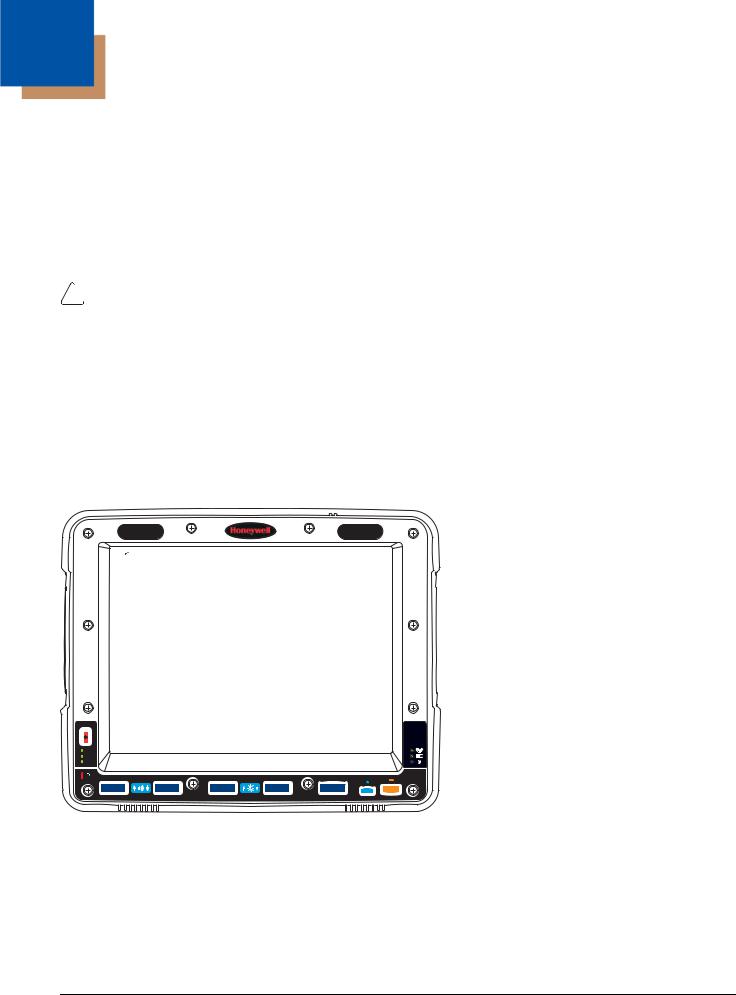
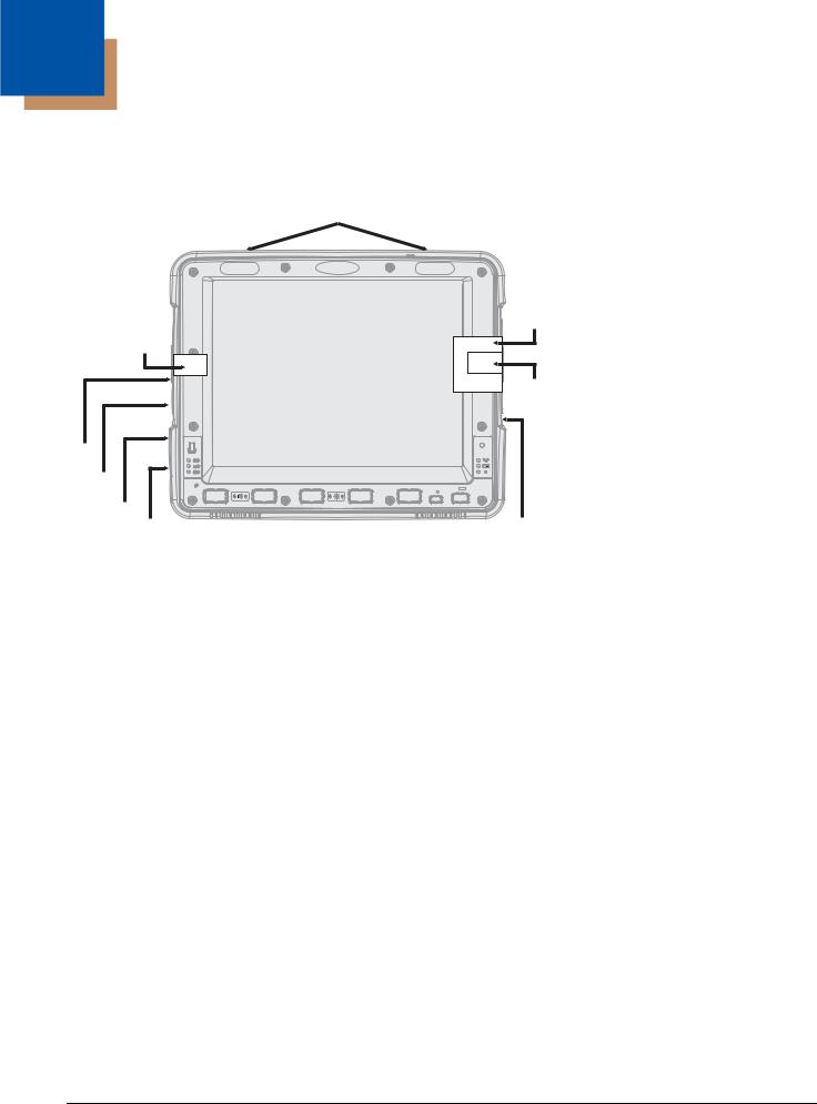
Components
Front View
Microphone
Power
Button
 SYS
SYS
UPS |
Wi Fi |
 SSD
SSD
 P
P
Speakers
Back View with Quick Mount Smart Dock
Antenna Connectors |
Strain Relief |
|
|
|
|
|
|
Clamps |
|
|
RAM Ball |
SD Card |
|
SIM Card |
Access |
|
Access Panel |
Panel |
|
|
Fuse |
|
COM1 Connector |
Power |
|
COM2 Connector |
Connector |
|
|
|
|
|
Power |
|
USB Connector |
Switch |
|
CANbus/Audio |
Provision for |
|
|
|
Connector |
|
Laptop Security |
|
|
|
|
|
Cable |
|
|
Provision for Padlock |
Quick Release Handle |
|
2 - 4
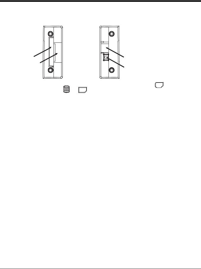
Access Panels
SD Card Access Panel with door removed |
SIM Card Access Panel with door removed |
|||||||||
|
|
|
|
|
|
|
|
|
|
|
|
|
|
|
|
|
|
|
|
|
|
|
|
|
|
|
|
|
|
|
|
|
|
|
|
|
|
|
|
|
|
|
|
CompactFlash |
SIM Card Slot |
|
Hard Drive |
||
for WWAN Radio |
||
|
||
SD (Secure Digital) |
UPS Battery |
|
Memory Card Slot |
||
Disconnect |
||
|
|
SSD |
SIM . |
|
Access Panel Door is labeled with |
|
Access Panel Door is labeled with |
and SD . |
|
2 - 5

Backlights and Indicators
Display Backlight
There are several configuration options for the Thor VM2 display backlight:
Power Management
The display backlight is controlled by power management. When the user activity timer expires, the display backlight is turned off. Timeouts can be set for the available power management schemes.
See Power Options (page 5-22) for configuration options.
Backlight Brightness
The intensity of the display backlight can be manually configured:
1.Press the Blue key to enter Blue mode
2.Press the P3 key to increase backlight brightness or the P4 key to decrease backlight brightness.
3.Press the Blue key to exit Blue mode.
Refer to the Screen Control (page 5-46) panel for the current display brightness level.
Screen Blanking
The Thor VM2 can be configured to blank (blackout) the display while the vehicle is in motion.
Refer to the Screen Control (page 5-46) panel for information.
Keypad Backlight
By default, the integrated keypad backlight follows the display backlight. The integrated keypad backlight can be disabled. To change this behavior, see the Options (see page 5-21) control panel.
The external USB keyboard backlight is manually controlled.
Speaker Volume
The speaker volume can be adjusted via the Thor VM2 keypad:
1.Press the Blue key to enter Blue mode
2.Press the P1 key to increase speaker volume or the P2 key to decrease speaker volume.
3.Press the Blue key to exit Blue mode.
The current volume level can be viewed on the Sounds (page 5-48) control panel or via the system tray speaker icon. These items can also be used to adjust speaker volume
2 - 6
Power Up
! |
If a USB drive, such as a thumb drive is attached to the Thor VM2, the device attempts to boot from the USB drive and |
cannot. Please remove the USB drive and power up the Thor VM2 again. |
The Quick Mount Smart Dock has a power switch on the back.
The “On” side of this rocker switch has a raised bump to allow the state of the switch to be determined when the switch may not be easily viewed, for example, after the dock is mounted in a vehicle.
After external power has been connected and the Thor VM2 has been mounted in the dock, press the side of the power switch with the raised bump to pass power from the dock to the Thor VM2.
Next locate the power button on the front of the Thor VM2.
 SYS
SYS
 UPS
UPS
 SSD
SSD
 P
P
Press the power button to turn the Thor VM2 on. When the Windows desktop is displayed or an application begins, the power up sequence is complete.
See Power Controls (see page 3-5) for more information.
2 - 7

Rebooting the Thor VM2
!• If the USB drive contains a bootable sector, the Thor VM2 boots from the USB drive.
•If the USB drive does not contain a bootable sector, the Thor VM2 does not boot. Remove the USB drive and boot the Thor VM2 again.If a USB drive, such as a thumb drive is attached to the Thor VM2, the device attempts to boot from the USB drive:
Restart
Restart performs a controlled shutdown of the Thor VM2 and then restarts the device.
•Use the Ctrl + Alt + Del keypress sequence to start the task manager. Tap the Shut Down button and select Restart from the pull-down list. Tap the OK button to restart the Thor VM2.
•Select Start > Shut Down > Restart and tap OK to restart the Thor VM2
Tapping the Touch Screen with a Stylus
Note: Always use the point of the stylus for tapping or making strokes on the touch screen.
Never use an actual pen, pencil, or sharp/abrasive object to write on the touch screen.
Hold the stylus as if it were a pen or pencil. Touch an element on the screen with the tip of the stylus then remove the stylus from the screen.
Firmly press the stylus into the stylus holder when the stylus is not in use.
Using a stylus is similar to moving the mouse pointer then left-clicking icons on a desktop computer screen.
Using the stylus to tap icons on the touch screen is the basic action that can:
•Open applications
•Choose menu commands
•Select options in dialog boxes or drop-down boxes
•Drag the slider in a scroll bar
•Select text by dragging the stylus across the text
•Place the cursor in a text box prior to typing in data
•Place the cursor in a text box prior to retrieving data using a scanner/imager.
A right click is generated by tapping the mouse icon , usually located in the upper right hand corner of the screen. After tapping, the mouse icon highlights the right button. The next touch screen tap is treated as a right click. The mouse icon returns to the left button highlighted so subsequent taps are treated as left clicks.
Note: If the mouse icon is not displayed, this feature can be enabled by tapping the PenMount icon  in the System Tray. From the menu that pops up, tap the Right Button to enable the mouse icon. When this option is enabled, a checkmark is displayed in the menu.
A stylus replacement kit is available.
When a dialog box is too large for the display, tap and drag the dialog box up or down or from side to side to view the remainder of the dialog box.
Setup Terminal Emulation Parameters
Note: The instructions below are for Honeywell RFTerm. If a different terminal emulation software is installed on your Thor VM2 refer to the documentation for that software.
Before you make a host connection, you will, at a minimum, need to know:
•the alias name or IP address (Host Address) and
•the port number (Telnet Port) of the host system to properly set up your host session.
1.Make sure the mobile client network settings are configured and functional. If you are connecting over wireless LAN (802.11x), make sure your mobile client is communicating with the Access Point.
2.From Start > Program, run RFTerm or tap the RFTerm icon on the desktop.
3.Select Session > Configure from the application menu and select the “host type” that you require. This will depend on the type of host system that you are going to connect to; i.e., 3270 mainframe, AS/400 5250 server or VT host.
2 - 8

4.Enter the “Host Address” of the host system that you wish to connect to. This may either be a DNS name or an IP address of the host system.
5.Update the telnet port number, if your host application is configured to listen on a specific port. If not, just use the default telnet port.
6.Select OK.
7.Select Session > Connect from the application menu or tap the “Connect” button on the Tool Bar. Upon a successful connection, you should see the host application screen displayed.
To change options such as Display, Colors, Cursor, Bar Code, etc., refer to these sections in the RFTerm Reference Guide for complete descriptions of these and other features.
Cleaning the Touch Screen
Note: These instructions are for components made of glass. If there is a removable protective film sheet on the display, remove the film sheet before cleaning the screen.
Keep fingers and rough or sharp objects away from the bar code reader scanning aperture and the mobile device touch screen.
If the glass becomes soiled or smudged, clean only with a standard household cleaner such as Windex® without vinegar or use isopropyl alcohol. Dampen the cloth with the cleaner and then wipe the surface.
Do not use paper towels or harsh-chemical-based cleaning fluids since they may result in damage to the glass surface. Use a clean, damp, lint-free cloth.
Do not scrub optical surfaces. If possible, clean only those areas which are soiled. Lint and particulates can be removed with clean, filtered canned air.
Startup Help
Contact Technical Assistance (page 9-1) if you need more help.
Touch screen is not accepting stylus |
Press Ctrl+Esc to force the Start Menu to appear. Use the tab, backtab and arrow keys |
taps or needs recalibration. |
to move the cursor from element to element. |
|
See Touch Screen Calibration (page 5-50). |
|
|
Thor VM2 seems to lockup as soon |
There may be slight delays while the wireless client connects to the network, authoriza- |
as it is rebooted. |
tion for voice-enabled applications complete, and Bluetooth relationships establish or re- |
|
establish. |
|
When an application begins, the Thor VM2 is ready for use. |
|
|
2 - 9

2 - 10
3
Hardware Overview
System Hardware
Antenna Connectors
CompactFlash
Hard Drive
SIM |
CF Slot |
|
Card |
||
|
SD Slot
Slot
SIM Slot
Secure
Digital
Memory
Card
Serial |
|
Connector |
SYS |
COM1 |
UPS |
|
SSD |
Serial
Connector  P
P
COM2
USB |
|
Connector |
Power |
CANbus/ |
|
Audio |
Connector |
Connector
802.11a/b/g/n Wireless Client
The Thor VM2 has an 802.11a/b/g/n network card that supports diversity with two internal or external antennas. Power management for the network card is configured with the Summit Client Utility (page 6-1).
Central Processing Unit
The CPU is a 1.6 GHz Intel Atom processor. The operating system is Microsoft Windows Embedded Standard 2009, Windows Embedded Standard 7 or Windows 7 Professional. The OS image is stored on an internal CompactFlash memory card and is loaded into DRAM for execution.
Input/Output Components
The Thor VM2 supports the following I/O components of the core logic:
•Two 9-pin RS-232 serial ports, COM1 and COM2.
•One slot for SD memory card.
•CompactFlash (CF) memory card drive.
•Integrated keyboard with programmable keys.
•Ports available via adapter cables: USB host port, CANbus, Audio. USB client port is not supported with Windows Embedded Standard 2009, Windows Embedded Standard 7 or Windows 7 Professional.
System Memory
Main system memory is 2 GB SDRAM.
Video Subsystem
The Thor VM2 video subsystem consists of a color TFT display. The video subsystem complies with the VESA VL bus standard. The resolution of this display is 1024x768 pixels. This resolution complies with the SVGA graphics industry standard.
The display supports screen blanking to eliminate driver distraction when the vehicle is in motion.
3 - 1

Audio Interface
Speakers are located on the bottom front of the Thor VM2. A headset adapter cable provides a connection for headset operation. When a headset is plugged into the adapter cable, the main speakers are disabled.
A microphone is located at the upper right of the Thor VM2 display, near the Thor VM2 emblem. When a headset is plugged into the adapter cable, the internal microphone is disabled.
Card Slots
CompactFlash (CF) Slot
The CF ATA slot is not hot swappable. The Thor VM2 must be powered down to insert or remove an ATA card. Since the operating system is stored on the CF ATA card, the Thor VM2 cannot operate without the ATA card.
Secure Digital (SD) Slot
The SD slot accepts an SD memory card. The SD card is hot swappable.
Bluetooth EZPair
The Thor VM2 contains Bluetooth version 2.0 with Enhanced Data Rate (EDR) up to 3.0 Mbit/s over the air. Bluetooth device connection (or pairing) can occur at distances up to 32.8 ft (10 meters) Line of Sight. The wireless client retains wireless connectivity while Bluetooth is active.
The user cannot select PIN authentication or encryption on connections from the Thor VM2. However, the Thor VM2 supports authentication requests from pairing devices. If a pairing device requests authentication or encryption, the Thor VM2 displays a prompt for the PIN or passcode. Maximum encryption is 128 bit. Encryption is based on the length of the user’s passcode.
Bluetooth simultaneously supports one printer as a slave Bluetooth device and one scanner, either as a slave or as a master Bluetooth device.
•The LED on the Bluetooth scanner illuminates during a scanning operation.
•Bar code data captured by the Bluetooth scanner can be manipulated by the settings in the optional Freefloat Link*One application.
•Multiple beeps may be heard during a bar code scan using a mobile Bluetooth scanner; beeps from the mobile Bluetooth scanner as the bar code data is accepted/rejected, and other beeps from the Thor VM2 during final bar code data manipulation.
WWAN
WWAN (Wireless Wide Area Networking) is available on the Thor VM2. A slot is provided for a SIM card.
GPS
GPS (Global Positioning System) is available on the Thor VM2.
Power
Vehicle DC Power Supply
Vehicle power input for the Thor VM2 dock is 10V to 60V DC and is accepted without the need to perform any manual operation within the Thor VM2 dock, see 12-48 VDC Vehicles (10-60 VDC Direct Connection) (page 4-18). The dock provides a conditioned power output for the Thor VM2. By using a specified DC/DC power supply, input voltage of 50-150V DC can be accepted, see 60-144 VDC Vehicles (50-150 VDC Power Supply, Screws on Top of Lid) (page 4-27) or 60-144 VDC Vehicles (50-150 VDC Power Supply, Screws on Top of Lid) (page 4-27).
Power input is fused for protection and the fuse is externally accessible, see Fuse (page 3-4).
External AC Power Supply
If DC power is not available – for example, in an office environment – an optional external Universal Input Power Supply can be used to convert AC wall power to an appropriate DC level. AC to DC power input for the Thor VM2 is delivered to the Quick Mount Smart Dock via an optional external power supply and adapter cable. See External AC/DC Power Supply
3 - 2

(page 4-36).
Uninterruptible Power Supply
The Thor VM2 contains an internal UPS battery.
The UPS battery is automatically charged when the Thor VM2 is placed in a powered dock, provided the safe charging temperature conditions below are met.
When external power is removed, the UPS automatically powers the Thor VM2 with no user intervention. When running on UPS power, the power management timeouts may be different than when vehicle power is applied.
The UPS allows the Thor VM2 to continue operation when not mounted in a dock or when the vehicle battery is being swapped. When fully charged the UPS battery is designed to power the Thor VM2 for a minimum of 30 minutes at temperatures of -20ºC (-4ºF) or greater.
If operating on UPS power and the UPS battery becomes critically low, the Thor VM2 performs a controlled shutdown.
If there is no external power available, there must be 10% or greater power in the UPS battery or the Thor VM2 does not power on.
The UPS status LED and the Battery Control Panel can be used to monitor the state of the UPS battery.
!Safety requirements restrict the temperature at which the Li-Ion UPS battery can be charged. Charging is disabled if the ambient temperature is outside of the 0ºC to 35ºC safe charging range. In order to maintain UPS charge the Thor VM2 should have power applied while the unit is within the safe charging range for at least an hour each day.
Safe Charging Temperature Range
The internal temperature of the Thor VM2 is the trigger for UPS battery charging.
•The UPS battery is not charged when the internal Thor VM2 temperature is below 0°C (32°F). This corresponds to an ambient (room) temperature of approximately -10°C (-14°F).
•The UPS battery is not charged when the internal Thor VM2 temperature is above 45°C (113°F). This corresponds to an ambient (room) temperature of approximately 35°C (95°F).
•If the UPS battery cannot be charged due to a temperature extreme, the UPS Status LED (page 3-11) is amber. Move the Thor VM2 to a different location to charge the UPS battery.
When the Thor VM2 is operated in an environment where the UPS battery is not able to charge due to temperature extremes, the Thor VM2 should be removed to a location within the safe charging temperature range during off hours. A discharged UPS battery cannot protect against data loss in the event vehicle power is interrupted.
Charging Timeout
•A fully discharged UPS battery normally recharges in less than 4 hours when the Thor VM2 is in a powered dock and within the safe charging temperature range.
•If the UPS battery is not charged before an 8 hour (or 4 hours for some earlier software revisions) timeout period expires, the UPS Status LED (page 3-11) is amber.
•The charge timeout is reset if charging resumes upon application of external power.
•The charge timeout is reset if charging resumes when the Thor VM2 enters the permissible temperature range for charging.
Charging and Power Management
• Charging does not occur when either Ignition Mode power scheme/plan is selected and the ignition is inactive.
Backup Battery
The Thor VM2 has a permanent Lithium battery installed to maintain time, date and CMOS setup information for a minimum of 90 days. The lithium battery is not user serviceable and should last four years with normal use before it requires replacement.
Note: The backup battery should only be changed by authorized service personnel.
3 - 3
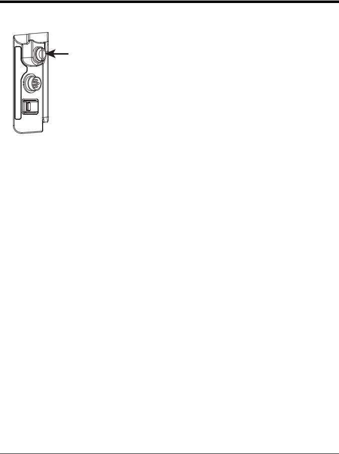
Fuse
The Thor VM2 uses an 8A time delay (slow blow), fuse that is externally accessible and user replaceable. The fuse is located on the back of the Quick Mount Smart Dock. The fuse is accessed by unscrewing the cap as indicated.
Should it need replacement, replace with same size, rating and type of fuse:
• Littelfuse 0215008.MXP
• Cooper Bussmann BK1/S506-8-R
• Bel Fuse 5HT 8-R
or equivalent.
Fuse has voltage on it even when power is off. Always disconnect input power before changing the fuse.
Power Management Modes
The Thor VM2 has four power modes: Full On, Standby/Sleep, Hibernate and Off.
Full On Mode
When the Thor VM2 is attached to either vehicle power or an external power supply or is operating from the UPS battery and the power button is pressed, the Thor VM2 is in the On mode. In this mode, the keypad, touch screen and any attached peripherals such as a scanner function normally. The display remains on until the display, standby or hibernate timer (if enabled) expires.
When in Full On mode, the status LED is solid green.
If the Thor VM2 is Full On, a press of the power button can be configured to put the unit in Standby. See the Advanced (page 5-34) tab of the Power control panel.
Standby/Sleep Mode
This mode is called Standby in Windows Embedded Standard 2009. This mode is called Sleep in Windows Embedded Standard 7 and Windows 7 Professional.
When the standby/sleep timer expires without a primary event occurring, the Thor VM2 transitions to Standby/Sleep mode. Pressing the Power button exits Standby/Sleep mode and transitions the Thor VM2 to Full On.
When in Standby/Sleep mode, the status LED:
•blinks green very slowly if external power is attached.
•is off if external power is not attached.
By default, power is turned off to the USB port when the Thor VM2 is in Standby/Sleep mode.
The Thor VM2 can be configured to provide power to the USB port in Standby/Sleep using the Options (page 5-21) control panel.
Note: Because the Thor VM2 with Windows Embedded Standard 7 or Windows 7 Professional cannot transition from Sleep to Hibernate due to an operating system limitation, Sleep is disabled by default in the predefined power plans. Power savings are significantly greater using Hibernate.
System Standby/Sleep Wakeup Events
The following events transition the Thor VM2 from Standby/Sleep to Full On Mode:
•Pressing and releasing the Power button
•Pressing or releasing any key on the integrated keypad
•Tapping the touch screen.
Hibernate Mode
When the Thor VM2 enters hibernate mode, all LEDs are off. Pressing the Power button returns the Thor VM2 to Full On.
3 - 4
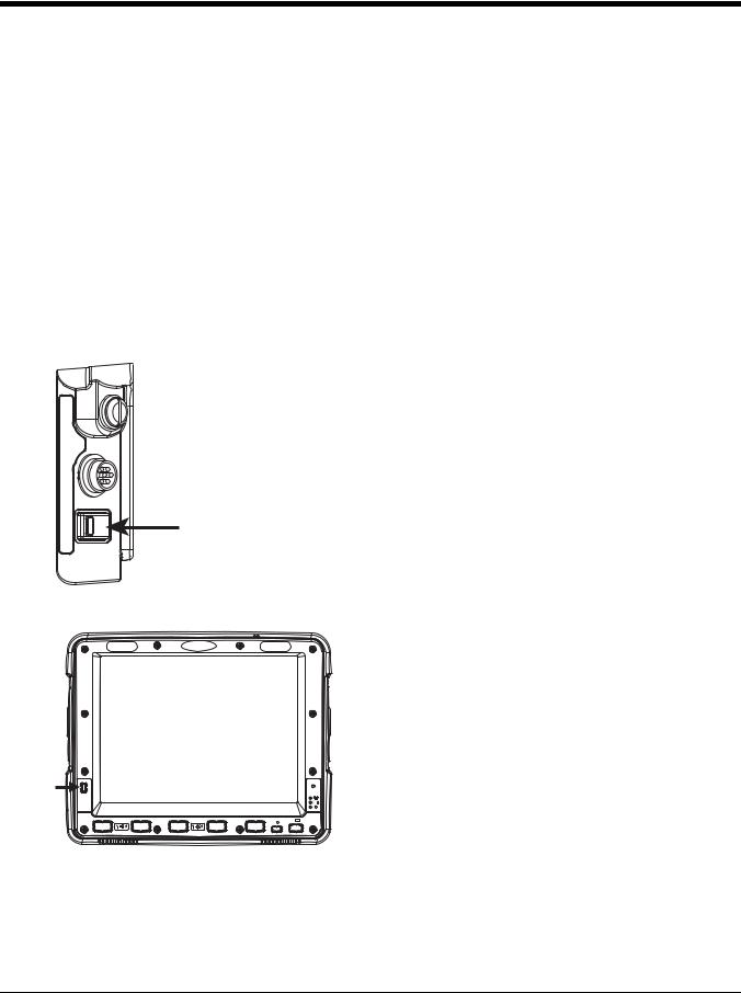
When in Hibernate Mode, the status LED:
•blinks green very slowly if external power is attached.
•is off if external power is not attached.
Power is turned off to the USB port when the Thor VM2 is in Hibernate.
System Hibernate Wakeup Events
The following event transitions the Thor VM2 from Hibernate to Full On Mode:
• Pressing and releasing the Power button.
Off Mode
By default, the Thor VM2 turns off if the user presses the power button when the Thor VM2 is On. This behavior can be configured on the Advanced (page 5-34) tab of the Power control panel.
The Thor VM2 is also off when it is not connected to a power source and the UPS battery is depleted. However, an internal Real Time Clock (RTC) powered by an internal battery maintains the date and time while the Thor VM2 is off.
Power Controls
Power Switch
After all cables are connected, the Thor VM2 can be powered on.
There is a power switch located on the back of the Quick Mount Smart Dock. The power switch is a rocker switch.
The power switch has a raised bump to identify the switch position even when it is hidden from view. When the side of the switch with the raised bump is pressed, the power switch is On. If the dock is connected to external power, the dock delivers power to the Thor VM2.
Generally, once the dock is powered On, there is no need to power it off. The dock power can remain On even when the Thor VM2 is not attached.
Power Button
 SYS
SYS
 UPS
UPS
 SSD
SSD
 P
P
The power button is located at the lower left of the Thor VM2.
If the Thor VM2 is Off, pressing the power button starts the power up sequence.
Note: This assumes that the Thor VM2 is docked in a powered Quick Mount Smart Dock or that the internal UPS battery has a sufficient charge to power the Thor VM2. If no external power is available and the UPS battery does not have a charge, pressing the power button causes no action.
If the Thor VM2 is On, pressing the power button performs the option selected in the Advanced tab of the Power control panel (options may vary by OS type):
•Ignore power button press
•Prompt the user to select action
•Shut down (default, an orderly shutdown is performed)
•Standby/Sleep
•Hibernate
Power Configuration
Use the Power Options (page 5-22) control panel to select the desired power scheme/plan.
For information on the Ignition input signal see Vehicle 10-60VDC Direct Power Connection (page 4-18) and Auto-On Control Wiring Diagram (page 4-21).
3 - 5
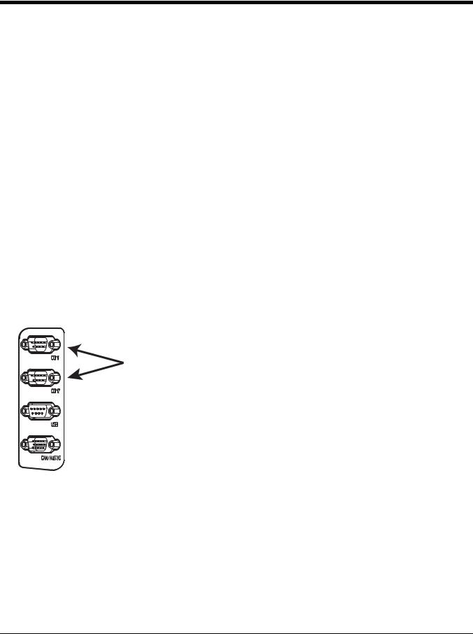
AC/DC
The Thor VM2 is powered on manually. When external power is present, the “Plugged In” power management timeouts are used,
Ignition Control
The Thor VM2 is configured to power on when the vehicle ignition is switched on. When either Ignition Control/ Ignition On or Ignition Control/Ignition Off is selected and external power is present, the Thor VM2 uses the “Pugged In” power management plan/scheme settings which corresponds to the state of the vehicle ignition.
Auto-On
The Thor VM2 is designed to power on whenever external power is present. When external power is present, the “Plugged In” power management timeouts are used.
UPS
The Thor VM2 uses the UPS mode whenever external power is not available. When external power is not present, the “Running on Batteries” or “On battery” power management timeouts from the selected power scheme/plan are used.
External Connectors
Power the Thor VM2 off before attaching a cable to any port (serial, USB, Audio/CAN, etc.).
The external I/O connectors for the Thor VM2 are located on the right side of the Quick Mount Smart Dock (when viewed from the back).
The Power Supply Connector (page 3-7) is on the left side of the dock (when viewed from the back).
Antenna connectors are located on the top rear of the Thor VM2.
Serial Connector (COM1 and COM2)
The COM1 and COM2 connectors are D-9 male connectors located on the back of the Quick
Mount Smart Dock.
Power the Thor VM2 off before attaching a cable to any port (serial, USB, Audio/CAN, etc.).
The serial connectors are industry-standard RS-232, PC/AT standard 9–pin “D” male connector. See COM1 and COM2 Connector (page 8-4) for connector pinout detail.
By default, Pin 9 is configured to provide +5V for an external bar code scanner. Pin 9 of
COM1 or COM2 may also be configured to provide RI.
See Connect Serial Device (page 4-38) for more information.
If a COM port is not being used for a scanner, it can be used for Screen Blanking (page 4- 33) when the vehicle is in motion.
Screen Blanking
The screen blanking signal can be provided either by a Honeywell Screen Blanking Box or a user supplied switch or relay. See Screen Blanking (page 4-33) for information on connecting screen blanking accessories.
3 - 6
Loading...