


 Loading...
PRELIMINARY
Notifier Wireless Sensor Network
LS10036-000NF-E
User Manual
Document LS10036-000NF-E N0
10/10/2013 Rev:
P/N LS10036-000NF-E:N0 |
ECN xx-xxx |
Fire Alarm & Emergency Communication System Limitations
While a life safety system may lower insurance rates, it is not a substitute for life and property insurance!
An automatic fire alarm system—typically made up of smoke |
(caused by escaping gas, improper storage of flammable materi- |
||
detectors, heat detectors, manual pull stations, audible warning |
als, etc.). |
||
devices, and a fire alarm control panel (FACP) with remote notifi- |
Heat detectors do not sense particles of combustion and alarm |
||
cation capability—can provide early warning of a developing fire. |
only when heat on their sensors increases at a predetermined |
||
Such a system, however, does not assure protection against |
rate or reaches a predetermined level. Rate-of-rise heat detec- |
||
property damage or loss of life resulting from a fire. |
tors may be subject to reduced sensitivity over time. For this |
||
An emergency communication system—typically made up of |
reason, the rate-of-rise feature of each detector should be tested |
||
an automatic fire alarm system (as described above) and a life |
at least once per year by a qualified fire protection specialist. |
||
safety communication system that may include an autonomous |
Heat detectors are designed to protect property, not life. |
||
control unit (ACU), local operating console (LOC), voice commu- |
IMPORTANT! Smoke detectors must be installed in the same |
||
nication, and other various interoperable communication meth- |
room as the control panel and in rooms used by the system for |
||
ods—can broadcast a mass notification message. Such a |
the connection of alarm transmission wiring, communications, |
||
system, however, does not assure protection against property |
signaling, and/or power. If detectors are not so located, a devel- |
||
damage or loss of life resulting from a fire or life safety event. |
oping fire may damage the alarm system, compromising its abil- |
||
The Manufacturer recommends that smoke and/or heat |
ity to report a fire. |
||
detectors be located throughout a protected premises following |
Audible warning devices such as bells, horns, strobes, |
||
the recommendations of the current edition of the National Fire |
speakers and displays may not alert people if these devices |
||
Protection Association Standard 72 (NFPA 72), manufacturer's |
are located on the other side of closed or partly open doors or |
||
recommendations, State and local codes, and the |
are located on another floor of a building. Any warning device |
||
recommendations contained in the Guide for Proper Use of |
may fail to alert people with a disability or those who have |
||
System Smoke Detectors, which is made available at no charge |
recently consumed drugs, alcohol, or medication. Please note |
||
to all installing dealers. This document can be found at http:// |
that: |
||
www.systemsensor.com/appguides/. A study by the Federal |
• An emergency communication system may take priority over |
||
Emergency Management Agency (an agency of the United |
|||
a fire alarm system in the event of a life safety emergency. |
|||
States government) indicated that smoke detectors may not go |
|||
• Voice messaging systems must be designed to meet intelligi- |
|||
off in as many as 35% of all fires. While fire alarm systems are |
|||
bility requirements as defined by NFPA, local codes, and |
|||
designed to provide early warning against fire, they do not |
|||
Authorities Having Jurisdiction (AHJ). |
|||
guarantee warning or protection against fire. A fire alarm system |
|||
• Language and instructional requirements must be clearly dis- |
|||
may not provide timely or adequate warning, or simply may not |
|||
function, for a variety of reasons: |
|
seminated on any local displays. |
|
Smoke detectors may not sense fire where smoke cannot |
• Strobes can, under certain circumstances, cause seizures in |
||
reach the detectors such as in chimneys, in or behind walls, on |
people with conditions such as epilepsy. |
||
roofs, or on the other side of closed doors. Smoke detectors |
• Studies have shown that certain people, even when they hear |
||
also may not sense a fire on another level or floor of a building. |
a fire alarm signal, do not respond to or comprehend the |
||
A second-floor detector, for example, may not sense a first-floor |
meaning of the signal. Audible devices, such as horns and |
||
or basement fire. |
|
bells, can have different tonal patterns and frequencies. It is |
|
Particles of combustion or “smoke” from a developing fire |
the property owner's responsibility to conduct fire drills and |
||
may not reach the sensing chambers of smoke detectors |
other training exercises to make people aware of fire alarm |
||
because: |
|
signals and instruct them on the proper reaction to alarm sig- |
|
• Barriers such as closed or partially closed doors, walls, chim- |
nals. |
||
• In rare instances, the sounding of a warning device can cause |
|||
neys, even wet or humid areas may inhibit particle or smoke |
|||
flow. |
|
temporary or permanent hearing loss. |
|
• Smoke particles may become “cold,” stratify, and not reach |
A life safety system will not operate without any electrical |
||
the ceiling or upper walls where detectors are located. |
power. If AC power fails, the system will operate from standby |
||
• Smoke particles may be blown away from detectors by air |
batteries only for a specified time and only if the batteries have |
||
been properly maintained and replaced regularly. |
|||
outlets, such as air conditioning vents. |
|
||
|
Equipment used in the system may not be technically compat- |
||
• Smoke particles may be drawn into air returns before reach- |
|||
ible with the control panel. It is essential to use only equipment |
|||
ing the detector. |
|
||
|
listed for service with your control panel. |
||
The amount of “smoke” present may be insufficient to alarm |
|||
Telephone lines needed to transmit alarm signals from a prem- |
|||
smoke detectors. Smoke detectors are designed to alarm at var- |
|||
ises to a central monitoring station may be out of service or tem- |
|||
ious levels of smoke density. If such density levels are not cre- |
|||
porarily disabled. For added protection against telephone line |
|||
ated by a developing fire at the location of detectors, the |
|||
failure, backup radio transmission systems are recommended. |
|||
detectors will not go into alarm. |
|
||
|
The most common cause of life safety system malfunction is |
||
Smoke detectors, even when working properly, have sensing |
|||
inadequate maintenance. To keep the entire life safety system in |
|||
limitations. Detectors that have photoelectronic sensing cham- |
|||
excellent working order, ongoing maintenance is required per the |
|||
bers tend to detect smoldering fires better than flaming fires, |
|||
manufacturer's recommendations, and UL and NFPA stan- |
|||
which have little visible smoke. Detectors that have ionizing-type |
|||
dards. At a minimum, the requirements of NFPA 72 shall be fol- |
|||
sensing chambers tend to detect fast-flaming fires better than |
|||
lowed. Environments with large amounts of dust, dirt, or high air |
|||
smoldering fires. Because fires develop in different ways and |
|||
velocity require more frequent maintenance. A maintenance |
|||
are often unpredictable in their growth, neither type of detector is |
|||
agreement should be arranged through the local manufacturer's |
|||
necessarily best and a given type of detector may not provide |
|||
representative. Maintenance should be scheduled monthly or as |
|||
adequate warning of a fire. |
|
||
|
required by National and/or local fire codes and should be per- |
||
Smoke detectors cannot be expected to provide adequate warn- |
|||
formed by authorized professional life saftety system installers |
|||
ing of fires caused by arson, children playing with matches |
|||
only. Adequate written records of all inspections should be kept. |
|||
(especially in bedrooms), smoking in bed, and violent explosions |
|||
Limit-D-1-2013 |
|||
2 |
PRELIMINARY: Notifier Wireless Sensor Network — P/N LS10036-000NF-E:N0 10/10/2013 |
||
Installation Precautions
Adherence to the following will aid in problem-free installation with long-term reliability:
WARNING - Several different sources of power can be connected to the fire alarm control panel. Disconnect all sources of power before servicing. Control unit and associated equipment may be damaged by removing and/or inserting cards, modules, or interconnecting cables while the unit is energized. Do not attempt to install, service, or operate this unit until manuals are read and understood.
CAUTION - System Re-acceptance Test after Software Changes: To ensure proper system operation, this product must be tested in accordance with NFPA 72 after any programming operation or change in site-specific software. Reacceptance testing is required after any change, addition or deletion of system components, or after any modification, repair or adjustment to system hardware or wiring. All components, circuits, system operations, or software functions known to be affected by a change must be 100% tested. In addition, to ensure that other operations are not inadvertently affected, at least 10% of initiating devices that are not directly affected by the change, up to a maximum of 50 devices, must also be tested and proper system operation verified.
This system meets NFPA requirements for operation at 0-49º C/32-120º F and at a relative humidity 93% ± 2% RH (noncondensing) at 32°C ± 2°C (90°F ± 3°F). However, the useful life of the system's standby batteries and the electronic components may be adversely affected by extreme temperature ranges and humidity. Therefore, it is recommended that this system and its peripherals be installed in an environment with a normal room temperature of 15-27º C/60-80º F.
Verify that wire sizes are adequate for all initiating and indicating device loops. Most devices cannot tolerate more than a 10% I.R. drop from the specified device voltage.
Like all solid state electronic devices, this system may operate erratically or can be damaged when subjected to lightning induced transients. Although no system is completely immune from lightning transients and interference, proper grounding will reduce susceptibility. Overhead or outside aerial wiring is not recommended, due to an increased susceptibility to nearby lightning strikes. Consult with the Technical Services Department if any problems are anticipated or encountered.
Disconnect AC power and batteries prior to removing or inserting circuit boards. Failure to do so can damage circuits.
Remove all electronic assemblies prior to any drilling, filing, reaming, or punching of the enclosure. When possible, make all cable entries from the sides or rear. Before making modifications, verify that they will not interfere with battery, transformer, or printed circuit board location.
Do not tighten screw terminals more than 9 in-lbs. Overtightening may damage threads, resulting in reduced terminal contact pressure and difficulty with screw terminal removal.
This system contains static-sensitive components.
Always ground yourself with a proper wrist strap before handling any circuits so that static charges are removed from the body. Use static suppressive packaging to protect electronic assemblies removed from the unit.
Follow the instructions in the installation, operating, and programming manuals. These instructions must be followed to avoid damage to the control panel and associated equipment. FACP operation and reliability depend upon proper installation.
Precau-D1-9-2005
HARSH™, NIS™, and NOTI•FIRE•NET™ are all trademarks; and Acclimate® Plus, FlashScan®, NION®, NOTIFIER®, ONYX®, ONYXWorks®, UniNet®,
VeriFire®, and VIEW® are all registered trademarks of Honeywell International Inc.HARSH™ is a trademark; and Acclimate®, FlashScan®, NION®, and
VIEW® are all registered trademarks of Honeywell International Inc. MULTI-NET™, Multi-Net Manager™, Unimode Network™, Unimode Network Manager™, and Uni-Tility™ are trademarks of Tyco Integrated Security. Echelon® is a registered trademark and LonWorks™ is a trademark of Echelon Corporation. ARCNET® is a registered trademark of Datapoint Corporation. Microsoft® and Windows® are registered trademarks of the Microsoft Corporation.
©2013 by Honeywell International Inc. All rights reserved. Unauthorized use of this document is strictly prohibited.
PRELIMINARY: Notifier Wireless Sensor Network — P/N LS10036-000NF-E:N0 10/10/2013 |
3 |
Software Downloads
In order to supply the latest features and functionality in fire alarm and life safety technology to our customers, we make frequent upgrades to the embedded software in our products. To ensure that you are installing and programming the latest features, we strongly recommend that you download
Documentation Feedback
Your feedback helps us keep our documentation up- to-date and accurate. If you have any comments or suggestions about our online Help or printed manuals, you can email us.
Please include the following information:
•Product name and version number (if applicable)
•Printed manual or online Help •Topic Title (for online Help) •Page number (for printed manual)
the most current version of software for each product prior to commissioning any system. Contact Technical Support with any questions about software and the appropriate version for a specific application.
•Brief description of content you think should be improved or corrected
•Your suggestion for how to correct/improve documentation
Send email messages to:
FireSystems.TechPubs@honeywell.com
Please note this email address is for documentation feedback only. If you have any technical issues, please contact Technical Services.
4 |
PRELIMINARY: Notifier Wireless Sensor Network — P/N LS10036-000NF-E:N0 10/10/2013 |

|
Table of Contents |
Table of Contents |
|
Section 1: About This Guide.................................................................................................... |
8 |
1.1: Purpose .......................................................................................................................................................... |
8 |
1.2: Assumed Knowledge ..................................................................................................................................... |
8 |
1.3: Site Survey..................................................................................................................................................... |
8 |
1.4: Abbreviations and Meanings ......................................................................................................................... |
9 |
Section 2: FWSG..................................................................................................................... |
10 |
2.1: Description................................................................................................................................................... |
10 |
2.2: Agency Approvals ....................................................................................................................................... |
10 |
2.2.1: FCC.................................................................................................................................................... |
10 |
2.3: Specifications............................................................................................................................................... |
11 |
2.3.1: Environmental Specification ............................................................................................................. |
11 |
2.4: Installing FWSG .......................................................................................................................................... |
11 |
2.4.1: Before Installing ................................................................................................................................ |
11 |
2.5: Mounting & Wiring ..................................................................................................................................... |
12 |
2.5.1: Mounting ........................................................................................................................................... |
12 |
2.5.2: Wiring................................................................................................................................................ |
14 |
2.5.3: FWSG Powered from SLC................................................................................................................ |
15 |
2.5.4: FWSG Powered from an External +24VDC Source ......................................................................... |
16 |
2.6: Configuration and Programming ................................................................................................................. |
17 |
2.6.1: Without a PC-based Configuration Tool........................................................................................... |
17 |
Create a New Profile ............................................................................................................................ |
17 |
Assign a Previously Created Profile Using a Distributor..................................................................... |
18 |
Removing a Profile............................................................................................................................... |
18 |
Create Mesh Network........................................................................................................................... |
18 |
2.6.2: With a PC-based Configuration Tool ................................................................................................ |
19 |
Assigning Profile with PC Tools.......................................................................................................... |
19 |
Removing Profile with PC Tools ......................................................................................................... |
20 |
Mesh Formation with PC Tools ........................................................................................................... |
21 |
2.6.3: Profile Distribution............................................................................................................................ |
21 |
2.6.4: SLC Configuration ............................................................................................................................ |
22 |
2.7: Operations.................................................................................................................................................... |
22 |
2.7.1: FWSG Modes Of Operation.............................................................................................................. |
22 |
Start Up................................................................................................................................................. |
22 |
Factory Default..................................................................................................................................... |
23 |
Profile Configured................................................................................................................................ |
23 |
Mesh Formation.................................................................................................................................... |
23 |
Initial Mesh Optimization..................................................................................................................... |
23 |
Normal Mode........................................................................................................................................ |
24 |
Rescue Mode ........................................................................................................................................ |
24 |
Mesh Optimization ............................................................................................................................... |
24 |
Bootloader ............................................................................................................................................ |
24 |
2.7.2: Magnet Sensor Activations................................................................................................................ |
24 |
Profile Magnetic Sensor ....................................................................................................................... |
24 |
Mesh Formation Magnetic Sensor........................................................................................................ |
24 |
2.7.3: LED Indications................................................................................................................................. |
24 |
2.7.4: Lock/Unlock FWSG.......................................................................................................................... |
28 |
Lock/Unlock FWSG through FACP .................................................................................................... |
28 |
Lock/Unlock FWSG through PC tools................................................................................................. |
28 |
Password Reset..................................................................................................................................... |
29 |
2.7.5: Weak Link Trouble Reporting........................................................................................................... |
29 |
Disabling Trouble Reporting at the FWSG Using PC Tools ............................................................... |
29 |
Disabling Trouble Reporting in the Panel............................................................................................ |
30 |
2.7.6: Collapse Network Command............................................................................................................. |
30 |
PRELIMINARY: Notifier Wireless Sensor Network — P/N LS10036-000NF-E:N0 10/10/2013 |
5 |

Table of Contents |
|
Collapsing Mesh Network Using PC Tools ......................................................................................... |
30 |
Collapsing Mesh Network in the Panel ................................................................................................ |
31 |
2.7.7: Silence Network Command............................................................................................................... |
31 |
Silencing Mesh Network Using PC Tools............................................................................................ |
31 |
Silencing Mesh Network in the Panel .................................................................................................. |
32 |
2.7.8: Multiple Wireless Sensor Network Installation Restrictions............................................................. |
33 |
2.7.9: Avoiding RF Interference .................................................................................................................. |
33 |
2.7.10: Trouble States .................................................................................................................................. |
34 |
2.7.11: History Events ................................................................................................................................. |
36 |
FWSG History Entries.......................................................................................................................... |
36 |
Section 3: Devices .................................................................................................................. |
38 |
3.1: Description................................................................................................................................................... |
38 |
Subsystem Overview ............................................................................................................................ |
38 |
FWD-200P- Wireless Photoelectric Smoke Detector (FCC ID AUBWFSSD). ............................... |
38 |
FWD-200ACCLIMATE- Wireless Acclimate (FCC ID AUBWFSSD) .......................................... |
38 |
FWH-200ROR135- Wireless Rate of Rise Heat Detector (FCC ID AUBWFSSD) ......................... |
38 |
FWH-200FIX135- Wireless Fixed Heat Detector (FCC ID AUBWFSSD) ..................................... |
38 |
FW-MM- Wireless Monitor Module (FCC ID AUBWFSMM) . ..................................................... 38 |
|
3.2: Agency Approvals ....................................................................................................................................... |
38 |
3.2.1: FCC.................................................................................................................................................... |
38 |
3.3: Specifications............................................................................................................................................... |
39 |
3.4: Installing Devices......................................................................................................................................... |
39 |
3.5: Mounting & Wiring...................................................................................................................................... |
39 |
3.6: Configuration and Programming ................................................................................................................. |
39 |
3.6.1: Assigning Profiles.............................................................................................................................. |
40 |
Assigning Profile Using PC Tools........................................................................................................ |
40 |
Assigning Profile to a Device with an FWSG or Distributor ............................................................... |
41 |
Transfer Profile from an FWSG/Distributor to Detector..................................................................... |
41 |
Transfer Profile from an FWSG/Distributor to Module...................................................................... |
41 |
3.6.2: Distributor Mode ............................................................................................................................... |
42 |
Converting a Device into a Distributor................................................................................................. |
42 |
Converting a Distributor Back into a Device ....................................................................................... |
42 |
3.6.3: Mesh Formation................................................................................................................................. |
43 |
Repeater ................................................................................................................................................ |
43 |
3.6.4: Restoring a Device to Factory Default .............................................................................................. |
43 |
Removing Profiles without PC-based Configuration Tool................................................................... |
43 |
Removing Profile with PC Tools.......................................................................................................... |
43 |
3.7: Device Operations........................................................................................................................................ |
44 |
3.7.1: Modes of Operation ........................................................................................................................... |
44 |
Factory Default ..................................................................................................................................... |
44 |
Profile Assigned.................................................................................................................................... |
44 |
Bootloader............................................................................................................................................. |
45 |
Distributor............................................................................................................................................. |
45 |
Mesh Participant ................................................................................................................................... |
45 |
Mesh Formation Mode ........................................................................................................................ |
45 |
Initial Mesh Optimization Mode ......................................................................................................... |
45 |
Normal Mode....................................................................................................................................... |
45 |
Rescue Mode ....................................................................................................................................... |
45 |
3.7.2: LED Indications................................................................................................................................. |
45 |
3.7.3: Trouble States .................................................................................................................................... |
49 |
Trouble States with Fire Protection ...................................................................................................... |
49 |
Class A Fault ....................................................................................................................................... |
49 |
Weak Link ........................................................................................................................................... |
49 |
Low Battery ......................................................................................................................................... |
49 |
Trouble States without Fire Protection................................................................................................. |
49 |
Tamper................................................................................................................................................. |
49 |
6 |
PRELIMINARY: Notifier Wireless Sensor Network — P/N LS10036-000NF-E:N0 10/10/2013 |

|
Table of Contents |
Duplicate Address ............................................................................................................................... |
50 |
No Answer........................................................................................................................................... |
50 |
Jamming .............................................................................................................................................. |
50 |
Device Initialization ............................................................................................................................ |
50 |
3.7.4: Background Events............................................................................................................................ |
51 |
Pre-Class A Fault.................................................................................................................................. |
51 |
Device Drop.......................................................................................................................................... |
51 |
Weak Link ............................................................................................................................................ |
51 |
Section 4: USB Adapter.......................................................................................................... |
52 |
4.1: Introduction.................................................................................................................................................. |
52 |
4.2: Agency Approvals ...................................................................................................................................... |
52 |
4.2.1: FCC.................................................................................................................................................... |
52 |
4.3: Specifications............................................................................................................................................... |
53 |
4.3.1: Electrical Specifications ................................................................................................................... |
53 |
4.3.2: Serial Communication Specification................................................................................................ |
53 |
4.3.3: Mechanical Specifications................................................................................................................ |
53 |
4.3.4: Environmental Specifications............................................................................................................ |
53 |
4.4: Driver Installation........................................................................................................................................ |
54 |
Appendix A: Site Survey ........................................................................................................ |
58 |
A.1: Description.................................................................................................................................................. |
58 |
A.1.1: Conducting Site Survey at the Job Site ............................................................................................ |
58 |
Link Quality Test.................................................................................................................................. |
58 |
Basic Requirements............................................................................................................................. |
58 |
Conduct a Link Test ............................................................................................................................ |
58 |
Results of Link Test.............................................................................................................................. |
59 |
Tasks After Link Test.......................................................................................................................... |
60 |
Link Quality Test and RF Scan Test .................................................................................................... |
60 |
Conduct a Link Test ............................................................................................................................. |
60 |
Results of Link Test.............................................................................................................................. |
61 |
Results of RF Scan Test ....................................................................................................................... |
61 |
Retrieving Site Survey Results............................................................................................................. |
61 |
Appendix B: PC Tools ............................................................................................................ |
62 |
B.1: Description .................................................................................................................................................. |
62 |
B.2: Launching PC Tools.................................................................................................................................... |
62 |
B.2.1: Creating Jobsite................................................................................................................................. |
63 |
B.2.2: Opening Jobsite................................................................................................................................. |
64 |
Appendix C: Troubleshooting and Testing .......................................................................... |
66 |
C.1: Troubleshooting .......................................................................................................................................... |
66 |
C.2: Testing FWSG and Devices ........................................................................................................................ |
66 |
C.2.1: Testing LED Indications................................................................................................................... |
66 |
C.3: Testing Wireless Network ........................................................................................................................... |
66 |
C.3.1: Network Topology............................................................................................................................ |
67 |
Parent-Child Devices............................................................................................................................ |
67 |
Orphan Devices .................................................................................................................................... |
67 |
Class A Compliance ............................................................................................................................. |
67 |
C.3.2: History Events................................................................................................................................... |
68 |
C.3.3: Network Snapshots ........................................................................................................................... |
68 |
C.3.4: Network Statistics ............................................................................................................................. |
68 |
C.3.5: Device Attributes .............................................................................................................................. |
68 |
Index......................................................................................................................................... |
69 |
PRELIMINARY: Notifier Wireless Sensor Network — P/N LS10036-000NF-E:N0 10/10/2013 |
7 |

About This Guide |
Purpose |
|
|
Section 1: About This Guide
1.1 Purpose
The Notifier Wireless Sensor Network user’s manual provides an overview of the following:
•Wireless fire alarm system.
•Instructions for installing and configuring the wireless devices.
•Information on monitoring the status of the wireless devices.
•Removal and replacement procedures of the FWSG.
•Testing, maintenance, and firmware upgrade information of the FWSG.
1.2Assumed Knowledge
The document is created with the assumption that all users arefamiliar with working on a PC and laptop for configuration purposes. Installers shouldbe familiar with Fire Alarm and Related Service Standards.
The terminology and level of details of this document reflect this assumption.
1.3 Site Survey
A site survey is recommended to assess and qualify the site prior to installing the Wireless Fire Alarm system. The site survey utility allows you to perform the Link quality test and radio frequency (RF) assessment of the site. This information is used for site qualification, maximum device spacing identification, and configuring the network. This helps to optimize the reliability and performance of the wireless network in the wireless fire alarm system. Conduct a site survey, and ensure there are no obstructions for using RF communications. For more information on a site survey, refer to Appendix A:, "Site Survey".
8 |
PRELIMINARY: Notifier Wireless Sensor Network — P/N LS10036-000NF-E:N0 10/10/2013 |

Abbreviations and Meanings |
About This Guide |
|
|
1.4 Abbreviations and Meanings
The following table lists the abbreviations and their definitions used in this manual.
Abbreviation |
Definition |
|
|
AHJ |
Authority Having Jurisdiction |
|
|
ANSI |
American National Standards Institute |
|
|
dBm |
Milli Decibel |
|
|
FACP |
Fire Alarm control Panel |
|
|
FCC |
Federal Communications Commission |
|
|
FWSG |
Fire Wireless System Gateway |
|
|
ISM Band |
Industrial, Scientific and Medical Radio |
|
Bands. |
|
|
LCD |
Liquid Crystal Display |
|
|
LED |
Light Emitting Diode |
|
|
mA |
Milliampere |
|
|
MHz |
Megahertz |
|
|
NFPA |
National Fire Protection Association |
|
|
PC |
Personal Computer |
|
|
RF |
Radio Frequency |
|
|
SLC |
Signaling Line Circuit |
|
|
UI |
User Interface |
|
|
UL |
Underwriters Laboratories |
|
|
USB |
Universal Serial Bus |
|
|
PRELIMINARY: Notifier Wireless Sensor Network — P/N LS10036-000NF-E:N0 10/10/2013 |
9 |

FWSG |
Description |
|
|
Section 2: FWSG
2.1 Description
The FWSG is a device in a wireless fire system th at acts as a bridge between fire alarm control panels and wireless fire devices. All wireless fire devices communicate with the FWSG over the wireless network formed by the devices and the FWSG.
The FWSG is powered by either the SLC loop orfrom any external 24VDC UL listed power supply. It uses FlashScan protocol on the SLC tocommunicate with the panel and a proprietary wireless protocol to communicate with wireless fire devices. The following graphic is an illustration of the components of the Firelite Wireless Sensor Network.
Figure 2.1 Wireless Fire Alarm System
2.2 Agency Approvals
2.2.1 FCC
This device complies with part 15 of the FCC Rules. Operation is subject to the following two conditions:
1.This device may not cause harmful interference, and
2.This device must accept any interference received, including interferences that may cause undesired operation.
FCC ID PV3WFSGW
WARNING: CHANGES OR MODIFICATIONS NOT EXPRESSLY APPROVED BY THE MANUFACTURER COULD VOID THE USER'S AUTHORITY TO OPERATE THE EQUIPMENT.
10 |
PRELIMINARY: Notifier Wireless Sensor Network — P/N LS10036-000NF-E:N0 10/10/2013 |
Specifications FWSG
2.3 Specifications
Following are the specifications of an FWSG.
Specifications |
Data |
|
|
External Supply Electrical Ratings |
18V-30V |
|
|
SLC Electrical Ratings |
15V-30V |
|
|
Maximum current when using the external supply |
40mA |
|
|
Maximum current when using the SLC power supply |
24mA |
|
|
Maximum SLC Resistance |
50 Ohms |
|
|
Minimum signal strength level needed at the receiver for a |
-50dBm |
primary path with weak link trouble reporting enabled. |
|
|
|
Minimum signal strength level needed at the receiver for a |
Must be 15 dBm higher than the noise floor |
secondary path or primary path with weak link trouble |
down to a minimum of -87dBm* |
reporting disabled. |
|
|
|
Maximum ambient noise level |
-90dBm |
|
|
Maximum RF Power Output |
+17dBm (Tx power level without antenna) |
|
|
Radio Frequency |
Lower ISM Band (915 MHz). |
|
|
NOTE: Devices that do not meet the minimum signal strength or have an ambient noise level that exceeds the limit are not allowed to join the mesh network.
2.3.1 |
Environmental Specification |
|
|
|||
|
|
|
|
|
|
|
|
|
System |
Operating Temperature |
|
Storage |
Humidity |
|
|
|
Temperature |
|||
|
|
|
|
|
|
|
|
|
|
|
|
|
|
|
|
FWSG |
0°C-49°C/32°F-120°F |
-10°C-60°C/14°F-140°F |
10 to 93% RH Non condensing |
|
|
|
|
|
|
|
|
2.4 Installing FWSG |
|
|
||||
2.4.1 |
Before Installing |
|
|
|||
Choose a location for the FWSG that is clean, dry, and vibration-free. The area should be readily accessible with sufficient room to easily install and maintain the FWSG. Metal obstructions that impede the radio frequency communication and should be avoided. Carefully unpack the system and inspect for shipping damage if any. All wiring must comply with the national and local codes for fire alarm systems.
PRELIMINARY: Notifier Wireless Sensor Network — P/N LS10036-000NF-E:N0 10/10/2013 |
11 |
FWSG |
Mounting & Wiring |
|
|
2.5 Mounting & Wiring
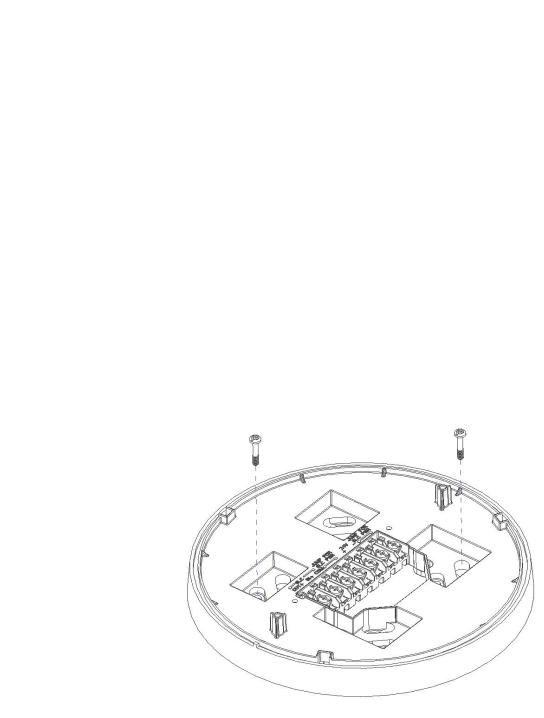
2.5.1 Mounting
The FWSG has two major pieces, the cover and the mounting plate. The mounting plate is mounted to the wall or ceiling and field wiring is connected to it. The cover contains the PC board and is fastened to the mounting plate once the wiring is connected.
Mount the mounting plate directly to an electrical box on the ceiling or wall. The plate mounts directly to 4˝ square (with and without plaster ring), 4˝ octagon, 3 1/2˝octagon, single gang or double gang junction boxes. If an electrical box is not available, the mounting plate can be mounted to any flat surface and the wiring can be connected via the knockout points in the mounting plate.
To mount the FWSG, do the following:
1.Pull the wiring through the opening in the mounting plate.
2.Mount the mounting plate to the junction box, wall or ceiling. See Figure 2.2, “Mounting Plate”.
3.Connect field wiring to the terminals, as described in 2.5.2 "Wiring".
4.Connect necessary jumpers where applicable, as described in 2.5.3 "FWSG Poweredfrom SLC".
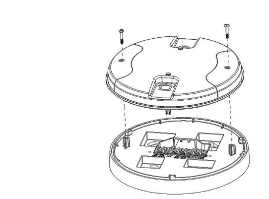
5.To mount the cover, align the locating pins on the cover to the corresponding slots in the mounting plate. See Figure 2.3, “Cover Attaching to Mounting Plate”.
6.Secure the cover by tightening the mounting screws.
Figure 2.2 Mounting Plate
12 |
PRELIMINARY: Notifier Wireless Sensor Network — P/N LS10036-000NF-E:N0 10/10/2013 |
Mounting & Wiring |
FWSG |
|
|
Figure 2.3 Cover Attaching to Mounting Plate
PRELIMINARY: Notifier Wireless Sensor Network — P/N LS10036-000NF-E:N0 10/10/2013 |
13 |

FWSG |
Mounting & Wiring |
|
|
2.5.2Wiring
•All wiring must be installed in compliance with the National Electrical Code and the local codes having jurisdiction.
•12-18 AWG is recommended.
Figure 2.4 Wiring Diagram with Terminal Descriptions
For wiring connections, follow this procedure:
•Strip about 3/8” of insulation from the end of the wire.
•Then, to make the wire connection, slide the bare end of the wire under the appropriate clamping plate, and tighten the clamping plate screw.
NOTE: Do not loop the wire under the clamping plate.
14 |
PRELIMINARY: Notifier Wireless Sensor Network — P/N LS10036-000NF-E:N0 10/10/2013 |
Mounting & Wiring |
FWSG |
|
|
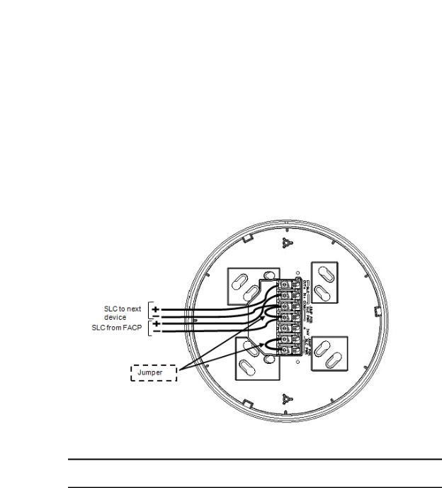
2.5.3 FWSG Powered from SLC
To power the FWSG using the signal line circuit, connect it as described in table 2.1 below:
Terminal Pins |
Description |
|
|
A5 & A7 |
SLC Common & SLC Output/Input |
|
|
A5 & A6 |
SLC Common & SLC Input/Output |
|
|
A4 & A5 |
Jumper selection to enable power from the SLC supply (Insert jumper when |
|
using SLC power) |
|
|
A3 |
Unused |
|
|
A1 & A2 |
Jumper selection to disable power from the external supply. (Insert jumper |
|
when using SLC power) |
|
|
|
Table 2.1 |
Figure 2.5 Wiring Connections (FWSG powered from SLC)
NOTE: It is recommended to use the same wire gauge if there are multiple connections to the same terminal.
The FWSG provides isolation of short circuits on the SLC in Class A installations, that use the A6 and A7 connections as an in and out connection. A5 is common for SLC wiring that enters and leaves. Class B wiring that terminates at the FWSG can use either the A6 or A7 connection for the SLC positive. SLC connections are power limited by the panel. An interruption in the SLC that causes a loss of power at the FWSG for more than 100ms may result in a trouble condition and loss of fire protection provided by the wireless devices for up to 15 minutes. Using an external 24V power source (not SLC power) is recommended for installations that require fire protection in the presence of short circuits, including class A applications and applications that utilize isolator modules.
PRELIMINARY: Notifier Wireless Sensor Network — P/N LS10036-000NF-E:N0 10/10/2013 |
15 |
FWSG |
Mounting & Wiring |
|
|
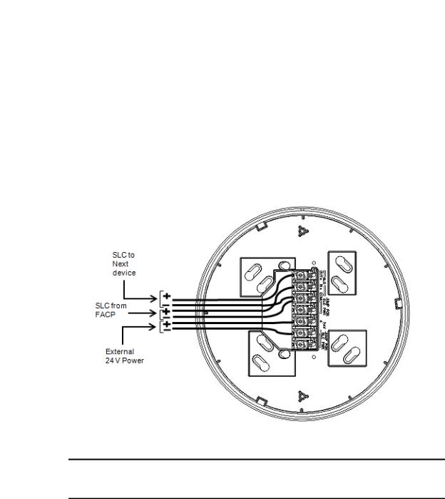
2.5.4 FWSG Powered from an External +24VDC Source
To power the FWSG using a +24VDC source, connect the FWSG as described in table 2.2 below.
Terminal Pins |
Devices Powered |
|
|
A5 & A7 |
SLC Input/output |
|
|
A5 & A6 |
SLC Input/output |
|
|
A4 |
Unused |
|
|
A2 & A3 |
+24VDC input. Voltage range from 18VDC to 30VDC. Use only power |
|
limited circuits |
|
|
A1 |
Unused |
|
|
|
Table 2.2 |
Figure 2.6 Wiring Connections -FWSG powered from an external +24VDC source
NOTE: Terminal A5 is referenced more than once in the above connections. It is recommended to use wire of the same gauge for all connections to A5 and use the same wire gauge if there are multiple connections to the same terminal.
The FWSG provides isolation of short circuits of the SLC in class A installations that use the A6and A7 as an in and out connection. A5 is common for in and out SLC wiring. Class B SLC wiring that terminates at the FWSG can use either the A6 or A7 connection for the SLC positive. SLC connections are power limited by the panel. 24VDC must be power limited by the source.
16 |
PRELIMINARY: Notifier Wireless Sensor Network — P/N LS10036-000NF-E:N0 10/10/2013 |
Configuration and Programming |
FWSG |
|
|
2.6 Configuration and Programming
The goal of configuring and/or programming the FWSG is to:
1.Create a profile - A profile is a set of parameters that binds together the FWSG and the devices in a mesh network.
2.Distribute the profile to every device that will be a part of the mesh.
3.Form the mesh - The mesh cannot be formed until the profile is assigned to the FWSG. The profile contains a mesh ID and, if required, a password, that are used when forming the associations. Creating and distributing the profile will enable all the devices that have that profile to form associative links when the mesh is formed. All devices, including the FWSG, require a common profile.
This section shows how to configure/program an FWSG with a profile, how to distribute that profile to other devices, and how to form all these devices into a mesh. These processes may be performed with or without using PC-based configuration tool.
2.6.1 Without a PC-based Configuration Tool
This section shows the configuration of the FWSG using only a magnet and a screw driver. For configuration instructions using the PC-based configuration tool, refer to 2.6.2 "With a PC-based Configuration Tool".
There are two ways to provide an FWSG with a profile without using a configuration tool.
•Create a new profile using the FWSG
•Assign a previously created profile to the FWSG using a distributor.
Create a New Profile
To create a unique profile in the FWSG without using the PC-based configuration tool, perform the following steps.
1.Start with the device powered off. The process is performed during the start-up.
2.Power on the FWSG using SLC power or external +24V. This can be done either by attaching the FWSG to its mounting plate with the terminals already energized, or by connecting the SLC or external source wiring to a FWSG that is already installed in its mounting plate.
3.Verify if the FWSG is in the factory default state; if it is in the factory default state, both the LEDs on the FWSG flash red (double blink) every second for ten seconds. If the LEDs are yellow, refer to the topic below on "Removing a Profile".
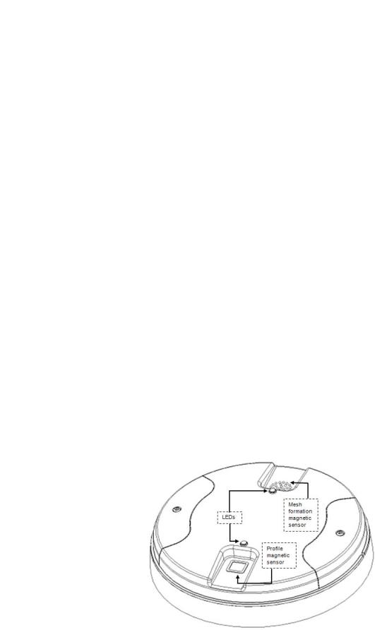
Figure 2.7 FWSG with LEDs and Magnetic Sensors
PRELIMINARY: Notifier Wireless Sensor Network — P/N LS10036-000NF-E:N0 10/10/2013 |
17 |

FWSG |
Configuration and Programming |
|
|
4.Activate either magnetic sensor with a magnet within ten seconds of starting up the FWSG while the double red blink is active on the FWSG. (If you miss this ten-second window, power down the FWSG and repeat step 1). The LED next to the magnetic sensor emits a red light for one second when it is activated.
When the profile is successfully created, the LEDs on the FWSG emit green light for five seconds (Refer to 2.7.2 "Magnet Sensor Activations" for further information on activating magnetic sensors). A default profile has been created, containing a mesh ID, and a password. The default password is ‘12345’ and is needed if the FWSG is locked by the FACP and later accessed by the PCbased configuration tool.
Next, the FWSG starts the profile distribution mode. Refer to 2.6.3 "Profile Distribution" for further information on profile distribution mode.
Assign a Previously Created Profile Using a Distributor
To assign an existing profile to the FWSG (as you would do during a replacement), use the FWSG that has the profile, or a device in the mesh that contains the profile, to distribute that profile to the FWSG that requires it. Perform the following steps:
1.Ensure that the FWSG or other mesh device with the profile is set for distribution (Refer to 2.6.3 "Profile Distribution" or 3.6.2 "Distributor Mode").
2.Start with the device powered off. The process is performed during the start-up.
3.Power on the FWSG and ensure it is in the factory default state (Refer to steps 1 and 2 in the above topic "Create a New Profile").
4.Bring the profile distributor within 20 feet of the FWSG.
5.Wait until the FWSG blinks only a single red blink (ten seconds after startup).
6.Use a magnet to activate either of the magnetic sensors. The LED blinks a single red every half-second indicating that it is searching for a profile.
When the profile is successfully received from the distributor, the LEDs on the FWSG emit green light for five seconds. If the profile is rejected, the FWSG LEDs emit red light for five seconds.
Removing a Profile
To remove the profile from an FWSG, perform the following steps:
1.Start with the device powered off. The process is performed during the start-up.
2.Power on the FWSG using SLC power or external +24V. This can be done either by attaching the FWSG to its mounting plate with the terminals already energized, or by connecting the SLC or external source wiring to a FWSG that is already installed in its mounting plate.
3.Verify the FWSG is in the profile modification state; if it is in the profile modification state, both the LEDs on the FWSG flash yellow (double blink) every second for ten seconds.
4.Activate both using magnetic sensors within ten seconds of starting up the FWSG (while the double yellow blink is active on the FWSG) or repeat step 1 (If you miss the ten second window, power down the FWSG and repeat steps 1 and 2).
The FWSG LEDs blink green every second for five seconds indicating that the profile is removed.
Create Mesh Network
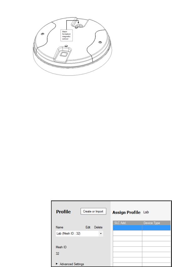
Mesh formation forms a wireless communication mesh around the FWSG. The FWSG communicates with all devices in range that have a common profile and establishes communication links with all the devices. Once a device joins the mesh, it acts as a repeater for devices out of the range of the FWSG. All devices must be in their final mounting locations prior to initiating the mesh formation. The mesh formation is initiated and terminated by the FWSG.
To form a mesh network, ensurethat the FWSG is powered on and containsa profile (Refer to 2.7.3 "LED Indications" for information on how the FWSG indicates its status). Activate the mesh formation magnet sensor on the FWSG with a magnet.
18 |
PRELIMINARY: Notifier Wireless Sensor Network — P/N LS10036-000NF-E:N0 10/10/2013 |
Configuration and Programming |
FWSG |
|
|
Figure 2.8 Mesh Formation Magnetic
Sensor on a FWSG
The FWSG transitions to the mesh formation mode and establishes communication with all the devices containing a common profile. The blink pattern on the FWSG indicates that it is in mesh formation mode.
•At this stage, both the LEDs on the FWSG blink twice every 3.4 seconds.
•The first blink is green and the second blink is red when the FWSG is acting as a profile distributor and forming the mesh.
•The first blink is green and the second blink is yellow when the FWSG is only forming the mesh.
Mesh formation typically takes one minute for each device in the mesh. Mesh formation automatically terminates 10 minutes after the last device joins the mesh. The mesh formation can be terminated manually by the user by activating the mesh formation magnetic sensor again.
Once the mesh formation is complete, the network transitions to optimize the mesh. For further operating instructions, refer to 2.7 "Operations".
2.6.2 With a PC-based Configuration Tool
Assigning Profile with PC Tools
To assign a profile to the FWSG using the PC Tools application, do the following:
1.Connect the W-USB dongle device to your computer. For more information on USB dongle, refer to Section 4: "USB Adapter".
2.Launch the PC Tools application. Refer Appendix B: "PC Tools" to know about launching the PC Tools application.
3.Go to the Create Mesh Network step.
4.Create a new profile or import an existing profile as required.
5.Select and open the profile to be assigned to the FWSG from the Name drop-down list in the left panel.
6.Power on the FWSG in range of the PC Tools.
PRELIMINARY: Notifier Wireless Sensor Network — P/N LS10036-000NF-E:N0 10/10/2013 |
19 |

FWSG |
Configuration and Programming |
|
|
7.Select the FWSG from the Communicator panel.
8.Click Assign.
The FWSG is now included in the list of devices with a profile assigned.
Removing Profile with PC Tools
To remove a profile in a FWSG using the PC Tools application, do the following:
1.Connect the W-USB dongle device to your computer. For more information on the USB dongle, refer to Section 4: "USB Adapter".
2.Launch the PC Tools application. Refer Appendix B: "PC Tools" to know about launching the PC Tools application.
3.Go to the Site Survey, Create Mesh Network, or Diagnostics step.
4.Click Extras and select Reset Devices. The Reset Devices screen appears, displaying the FWSG and other devices that have a profile assigned.
5.Click to select the FWSG and click Reset Device to remove the profile.
The profile is removed and the FWSG is reset to factory default state.
20 |
PRELIMINARY: Notifier Wireless Sensor Network — P/N LS10036-000NF-E:N0 10/10/2013 |
Configuration and Programming |
FWSG |
|
|
Mesh Formation with PC Tools
To create a mesh network using the PC Tools, perform the following steps.
1.Connect the W-USB dongle device to your computer. For more information on the USB dongle, refer to Section 4: "USB Adapter"
2.Launch the PC tools application. Refer Appendix B: "PC Tools" to know about launching the PC Tools application.
3.Go to the Create Mesh Network step.
4.Navigate to the second step of Create Mesh Network by clicking on top of the screen.
5.Click to select the FWSG displayed in the Gateways in Range table, and click 'Start Mesh Formation'.
When the mesh is formed, the tool helps you to track the number of devices that have joined the mesh, and view the progress. The mesh formation terminates in 10 minutes after the last device joins the mesh. In addition, it can be terminated by the user by clicking Stop Mesh Formation.
Once mesh formation is complete, the network transitions to optimize the mesh. For further operating instructions, refer to 2.7 "Operations".
2.6.3 Profile Distribution
There are two ways to initiate profile distribution from an FWSG.
•Automatically after creating a profile,
•Activating the profile creating magnetic sensor when it has a profile.
After Creating a Profile
Profile distribution is automatically enabled from an FWSG after creating a profile. The profile distribution automatically terminates after 10 minutes.
Activating the Profile Magnetic Sensor when it has a Profile
Activating the profile magnetic sensor while it has a profile will put an FWSG in a mode of distributing the profile to any device that requests a profile. The FWSG’s LED pattern will be altered when it is distributing a profile for easy identification. Profile distribution will automatically terminate after 10 minutes. For more information on FWSG LED patterns, refer to the table in 2.7.3 "LED Indications".
Figure 2.9 Profile Magnetic Sensor on
FWSG
PRELIMINARY: Notifier Wireless Sensor Network — P/N LS10036-000NF-E:N0 10/10/2013 |
21 |
FWSG |
Operations |
|
|
2.6.4 SLC Configuration
The FWSG,
•Communicates with the control panel via the SLC circuit.
•Is a FlashScan only device.
•CLIP mode is not supported.
•Is only compatible with Fire Alarm Control Panels version 21 or higher.
•Occupies one module SLC address. Set the address using the rotary dials on the FWSG prior to installation.
The point uses the following configuration parameters:
•Module Type: Monitor
•Type Code Label: RF GATEWAY
•Flash Scan Type: RF GATEWAY
An FWSG does not initiate alarms but the point is used for event reporting.
2.7Operations
2.7.1FWSG Modes Of Operation
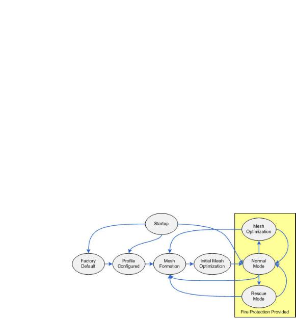
Figure 2.10 FWSG Modes Of Operation
Start Up
Startup is a temporary mode of operation. It is during the startup mode, a profile can be created or removed. The startup period lasts for 10 seconds. If a particular unit contains a profile, the LEDs blink yellow twice every second. If the unit does not contain a profile, the LEDs blink red twice every second.
During startup, the FWSG does not provide fire protection.
After startup, the FWSG proceeds to the factory default state if a profile was removed or missing. In the presence of a profile, the FWSG will proceed to mesh formation if it was previously part of a mesh network or normal mode if it was not previously part of a mesh network. The FWSG does not respond to the FACP during startup mode.
22 |
PRELIMINARY: Notifier Wireless Sensor Network — P/N LS10036-000NF-E:N0 10/10/2013 |

Operations |
FWSG |
|
|
Factory Default
Factory default is the initial mode of the FWSG. The FWSG and peripheral devices do not provide any fire protection when they are in factory default mode. The FWSG does not communicate with wireless devices. The only wireless communication is with the configuration tool. The configuration tool needs to be within 20 feet of the FWSG for communication. The FWSG needs to be assigned a profile before continuing the installation.
The FWSG reports a ‘PROFILE MISSING' or ‘PR MIS’ trouble to the FACP. The FWSG reports “Factory Default” to the communicator display of the PC Tools application.
Profile Configured
The FWSG enters the profile configured mode after getting assigned a profile from the tool or a distributor or creating a profile. Profile configured mode is a temporary mode before the FWSG transitions to mesh formation or normal mode.
The FWSG does not provide fire protection in the profile configured mode. While in the profile configured mode, the FWSG reports a "MESH NOT FORMED" or "NO MSH" trouble to the FACP. The FWSG reports “Profile Assigned” to the communicator display of the PC Tools application.
Mesh Formation
The FWSG must have a profile before entering mesh formation. The FWSG and the peripheral devices do not provide any fire protection in mesh formation. The FWSG automatically enters mesh formation mode in the following ways:
•After creating a profile using the mesh formation sensor.
•After activating the mesh formation sensor with a magnet when the FWSG contains a profile.
•Automatically after startup when the FWSG previously was part of a mesh.
•By command from the PC Tools application.
•By command from the FACP.
A FWSG in mesh formation mode instructs all devices in the mesh to also transition to mesh formation. The FWSG and all communicating devices search for new or lost devices with the same profile to join the network.
If the FWSG automatically entered mesh formation mode after startup, then mesh formation terminates after all existing devices are recovered. If new devices are found or if mesh formation was initiated by the user, then mesh formation terminates after a period of 10 minutes without any new devices joining the mesh. At any point, mesh formation can be terminated by user interaction by activating the magnet sensor again, by using the PC Tools application, or by using FACP.
The FWSG reports a “NO WIRELESS DEVS” or “NO DEV” trouble when it is in MeshFormation mode without any attached devices. The FWSG reports a “MESH IS FORMING” or “MS FRM” trouble when it is mesh formation mode with additional devices in the mesh. The FWSG reports “Mesh Formation” to the communicator display of the PC Tools application.
Initial Mesh Optimization
The initial mesh optimization mode automatically runs after each mesh formation. The FWSG and peripheral devices do not provide fire protection during the initial mesh optimization. Mesh optimization mode analyzes the signal strengths between devices. The FWSG designates the primary and secondary communication paths between devices that provide a redundant path for all transmissions. Mesh optimization terminates automatically once all devices have a redundant communication path and signal strengths that meet the requirements of primary and secondary transmission paths. Any device that does not have a redundant path or meet the requirements for signal strength will report a fault.
PRELIMINARY: Notifier Wireless Sensor Network — P/N LS10036-000NF-E:N0 10/10/2013 |
23 |
Loading...