


Excel 10
W7751H3007 VAV ACTUATORS
HONEYWELL EXCEL 5000 OPEN SYSTEM
INSTALLATION INSTRUCTIONS
BEFORE INSTALLATION
The W7751H Smart VAV Actuator consists of a factorycombined variable air volume (VAV) box controller and a direct-coupled damper actuator with de-clutch mechanism. The actuator/controller assembly is field-mounted to the VAV box damper shaft similar to the mounting of a standard actuator, and the controller wiring is terminated to the screw terminals accessible inside the detachable wiring box. See Fig. 2.
The W7751H's built-in actuator with de-clutch mechanism allows the installer to manually open or close its built-in VAV box damper without power or software tool.
The W7751H contains a Free Topology Transceiver (FTT) LonMark® compliant controller containing a Microbridge flowthrough pressure sensor and communicates via the 78 kbaud LONWORKS® Network.
The W7751H actuator mounts directly onto the VAV box damper shaft and has up to 6 Nm torque, 95 degree stroke, and 110 sec. timing at 50 Hz and 90 sec at 60 Hz.
If desired, the SSW2 Auxiliary Switch Kit (see "SSW2 Auxiliary Switch Kit for N05xx, N10xx Non-Spring Return Direct-Coupled Damper Actuators – Installation Instructions", Product Literature No.: MU1B-0284GE51) can be attached to the W7751H. See also section "Optional Accessories" on page 9.
NOTE: Any hardware driven by the triac outputs must have a min. current draw, when energized, of 25 mA at 24 Vac and a max. current draw of 770 mA.
MAIN FEATURES
Legend for Fig. 2:
1)Universal shaft adapter
2)Mechanical end limits (manually adjustable in increments of 5.5°)
3)Air flow pick-up connector (-LO)
4)Air flow pick-up connector (-HI)
5)LONWORKS service LED
6)Declutch button
7)LONWORKS service pin
8)Detachable wiring box
9)Anti-rotation bracket
Fig. 1. Excel 10 Smart VAV Actuator
1
2
3 |
|
4 |
|
6 |
5 |
|
|
|
7 |
9 |
8 |
|
Fig. 2. W7751H main features
® U.S. Registered Trademark |
|
EN1B-0279GE51 R0707B |
Copyright © 2007 Honeywell Inc. • All rights reserved |
|
|
|
|

EXCEL 10 W7751H SMART VAV ACTUATOR
INSTALLATION
The W7751H provides IP40 in all mounting orientations.
IP40 IP40
IP40
|
|
|
|
1112 |
|
3 4 5 |
6 7 |
8 9 |
10 |
1 2 |
|
|
||
|
|
|
||
|
|
|
|
360° 360°
Fig. 3. Permissible orientations providing IP40
Mount the W7751H on the damper shaft and allow clearance for wiring, servicing, and module removal. Avoid mounting the W7751H in areas where acid fumes or other corrosive vapors can attack the actuator's metal parts, or in areas where escaping gas or other explosive vapors are present. See Fig. 23 for mounting dimensions.
The W7751H is field-mounted to the VAV box damper shaft. The W7751H actuator opens or closes a damper by driving the damper shaft in either the counterclockwise (CCW) or clockwise (CW) direction. If the W7751H is to be mounted directly onto a damper shaft, use the mounting bracket and screw included in the delivery.
The wiring of the W7751H controller is terminated to a screw terminal block accessible inside the detachable wiring box. See section "Wiring".
The W7751H actuator is shipped in the fully counterclockwise (CCW) position (95 degrees). Mount the W7751H so that the actuator is parallel with the VAV box damper housing.
 CAUTION
Equipment damage hazard.
Mounting actuator unevenly with damper housing can damage actuator.
Mount the actuator flush with the damper housing or add a spacer between the anti-rotation bracket and the VAV damper box housing (see Fig. 6).
Fig. 4. Opening wiring box (1)
|
|
|
|
1112 |
|
3 4 5 |
6 7 |
8 9 |
10 |
|
|
|||
1 2 |
|
|
||
|
|
|
||
|
|
|
|
Fig. 5. Opening wiring box (2)
VAV box damper shaft
VAV box damper housing
spacer or washer 
Fig. 6. Mounting W7751H with washer/spacer
Before mounting the W7751H onto the VAV box damper shaft, do the following:
1. Ensure that the diameter of the damper shaft is within the allowed limits (round: 8…16 mm, square: 6…13 mm).
EN1B-0279GE51 R0707B |
2 |
EXCEL 10 W7751H SMART VAV ACTUATOR
2.Ensure that the damper shaft has a length of at least 40 mm.
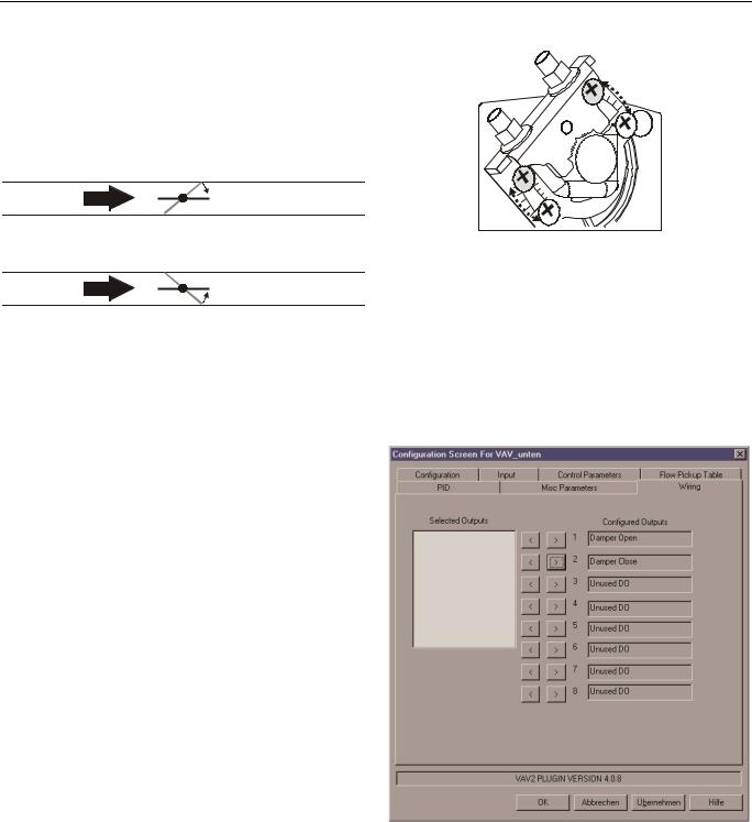
3.Determine the direction (CW or CCW) in which the damper shaft rotates to open the damper (see Fig. 7).
4.Determine the angle of the damper opening (can be adjusted in increments of 5.5°).
TYPE A DAMPER
COOLING
AIR FLOW
CW TO OPEN, CCW TO CLOSE
TYPE B DAMPER
COOLING
AIR FLOW
CCW TO OPEN, CW TO CLOSE
Fig. 7. Determining direction of rotation
The W7751H actuator is shipped in the fully counterclockwise (CCW) position (95 degrees). The installation procedure varies depending on the damper direction.
NOTE: Be aware that, until the W7751H is powered and the damper is driven open, starting the fan system with all the VAV box dampers closed can cause duct over-pressurization and damage.
If Damper Rotates CW to Open
If the damper rotates clockwise (CW) to open, mount the W7751H as follows:
1.Manually open the damper.
2.Push down the declutch button of the W7751H, and while holding it down, manually rotate its shaft adapter fully to the clockwise position.
3.Mount the W7751H to the VAV damper box and shaft.
4.Set the mechanical end limits of the W7751H (see Fig. 8). When the W7751H closes, the damper will thus rotate CCW until the mechanical end limits are reached.
If Damper Rotates CCW to Open
If the damper rotates counterclockwise (CCW) to open, mount the W7751H as follows:
1.Manually open the damper.
2.Push the declutch button of the W7751H, and while holding it down, manually rotate its shaft adapter fully to the counterclockwise position.
3.Mount the W7751H to the VAV damper box and shaft.
4.Set the mechanical end limits of the W7751H (see Fig. 8). When the W7751H closes, the damper will thus rotate CW until the mechanical end limits are reached.
Fig. 8. Setting the mechanical end limits
Reconfiguring to Match Rotation Direction
Using the LNS plug-in, the W7751H can be reconfigured to match the direction the damper shaft rotates to open the damper. Reconfigure the damper's direction of rotation to "open" or "closed," according to your needs.
To change the damper direction from CW to CCW using the LNS plug-in, proceed as follows.
1.Open the configuration part of the plug-in and select the "Wiring" tab (see Fig. 9).
Fig. 9. Wiring tab (default configuration)
2. Then deselect the output configuration (see Fig. 10).
3 |
EN1B-0279GE51 R0707B |
 Loading...