


VR8215S
Table of contents
 Loading...
INSTALLATION INSTRUCTIONS
34-00006EF-03
VR8215S,T Direct Ignition
Combination Gas Controls
APPLICATION
The Trade VR8215S,T Direct Ignition Combination Gas Controls are used in gas-fired appliances with up to
150 ft
3
/hr capacity at 1 in. wc pressure drop on natural gas. They have been optimized for direct ignition
applications and include a switch and a pressure regulator.
• Valve capacities are shown in Table 1.
• Table 2 provides gas capacity conversion factors.
• For suffix letter designation, see Table 3.
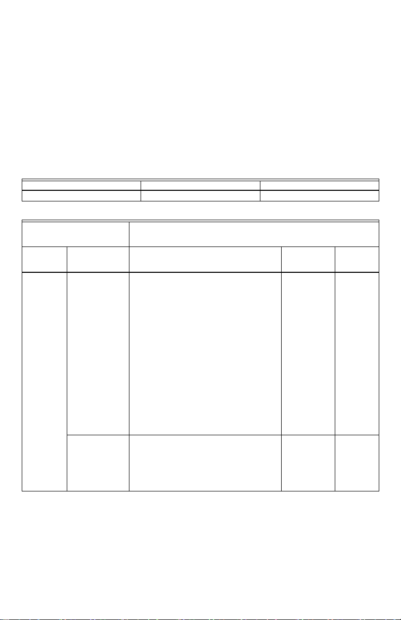
Table 1. Valve Capacity.
a
a
Capacity based on 1000 Btu/ft
3
, 0.64 sp gr natural gas at 1 in. wc pressure drop (37.3 MJ/m
3
, 0.64 sp gr natu-
ral gas at 0.25 kPa pressure drop).
b
Minimum regulation for LP gas is 30,000 Btu/h (0.85 m
3
/hr).
Table 2. Gas Capacity Conversion Factor. Table 3. Model Number Suffix Letter Designation.
Model
Size
Inlet x
Outlet (in.
NPT)
AGA Certified Capacity
for Natural Gas
AGA Certified
Minimum
Regulation for
Natural Gas
AGA Certified Maximum
Regulation for Natural
Gas
ft
3
/hr m
3
/hr ft
3
/hr m
3
/hr ft
3
/hr m
3
/hr
VR8215 1/2 x 1/2 150 4.25
15
b
0.42 200 5.66
Gas Specific Gravity
Multiply Listed
Capacity By
Manufactured 0.60 0.516
Mixed 0.70 0.765
Propane 1.53 1.62
Model Number Suffix
Letter
Pressure Regulator
Type
SStandard
TSlow Opening
VR8215S,T DIRECT IGNITION COMBINATION GAS CONTROLS
34-00006EF—03 2
SPECIFICATIONS
Body Pattern: Straight through; see Table 1 for inlet
and outlet size.
Electrical Ratings:
Voltage and Frequency: 24 Vac, 50/60 Hz.
Current Draw: 0.5A.
Field Wiring:
2-1/4 in. spade quick-connect terminals.
Capacity: See Table 1.
Conversion:
Use conversion factors in Table 2 to convert capacities
for other gases.
Regulation Range: See Table 7.
Natural-LP Gas Conversion Kits: See Table 4.
Approvals:
CSA Design Certificate #112395.
(-40 °F to +175 °F; -40 °C to +79 °C)
Australian Gas Association Certificate #7960.
(-20 °C to +79 °C only)
Outlet: Class 2, Grade 20 pressure regulator
Auto shutoff valve function: Class 3
Table 4. Natural-LP Gas Conversion Kits.
Model Number Suffix Letter Kit to Convert Natural Gas to LP Kit to Convert LP to Natural Gas
S, T 396221 396222
Table 5. Replacement Part Cross-Reference.
Trade Replacements
(Double-Check Specifications
Before Replacement) Competitive Replacement
Universal
Service Part
Direct Service
Part
Replacement Resideo White-Rogers
Robertshaw
VR8215 VR8215S1503 VR8205S2262, VR8205S2270,
VR8205S2296, VR8205S2338,
VR8205S2353, VR8205S2361,
VR8205S2379, VR8205S2395,
VR8205S2437, VR8205S2858,
VR8205S2882, VR8205S5802,
VR8205S5828, VR8205S5836,
VR8205S5844, VR8215S1222,
VR8215S1263, VR8215S5207,
VR8215S5215, VR8205A2008, VR8205A2016,
VR8205A2024, VR8205A2065, VR8205A2081,
VR8205A2131, VR8205A2263, VR8205A2800,
VR8205M1080, VR8205M1106,
VR8205M1122, VR8205M1130,
VR8205M1148, VR8205M1155,
VR8205M1163, VR8205M2310,
VR8205M2401, VR8205M2476,
VR8205M2484, VR8205M2831,
VR8205M2864, VR8205M2872,
VR8205M2880, VR8205M5024,
VR8205M5032
36G22-214,
36J22-214,
36G22-207
VR8215T1502 VR8205H1003, VR8205H1011,
VR8205H2605, VR8205H2621,
VR8205K1157, VR8205K1173,
VR8205K2247, VR8205K2593,
VR8205K2619, VR8205T5801,
VR8215T1205, VR8215T1239, VR8215T5206,
VR8215T5214

VR8215S,T DIRECT IGNITION COMBINATION GAS CONTROLS
3 34-00006EF—03
PLANNING THE
INSTALLATION
WARNING
Fire or Explosion Hazard.
Can cause property damage, severe injury,
or death.
Follow these warnings exactly:
1. Plan the installation as outlined below.
2. Plan for frequent maintenance as described
in the Maintenance section.
Heavy demands are made on the controls when direct
ignition systems are used on central heating
equipment in barns, greenhouses, and commercial
properties and on heating appliances such as
commercial cookers, agricultural equipment,
industrial heating equipment and pool heaters.
Special steps may be required to prevent nuisance
shutdowns and control failure due to frequent cycling,
severe environmental conditions related to moisture,
corrosive chemicals, dust or excessive heat. These
applications require Resideo Engineering review;
contact your Resideo Sales Representative for
assistance.
Review the following conditions that can apply to your
specific installation and follow the precautions
suggested.
Frequent Cycling
This control is designed for use on appliances that
typically cycle three to four times an hour only during
the heating season. In year-around applications with
greater cycling rates, the control can wear out more
quickly. Perform a monthly checkout.
Water or Steam Cleaning
If a control gets wet, replace it. If the appliance is likely
to be cleaned with water or steam, protect (cover) the
control and wiring from water or steam flow. Mount
the control high enough above the bottom of the
cabinet so it does not get wet during normal cleaning
procedures.
High Humidity or Dripping Water
Dripping water can cause the control to fail. Never
install an appliance where water can drip on the
control. In addition, high ambient humidity can cause
the control to corrode and fail. If the appliance is in a
humid atmosphere, make sure air circulation around
the control is adequate to prevent condensation. Also,
regularly check out the system.
Corrosive Chemicals
Corrosive chemicals can attack the control, eventually
causing a failure. If chemicals are used for routine
cleaning, avoid contact with the control. Where
chemicals are suspended in air, as in some industrial
or agricultural applications, protect the control with an
enclosure.
Dust or Grease Accumulation
Heavy accumulations of dust or grease can cause the
control to malfunction. Where dust or grease can be a
problem, provide covers for the control to limit
contamination.
Heat
Excessively high temperatures can damage the
control. Make sure the maximum ambient
temperature at the control does not exceed the rating
of the control. If the appliance operates at very high
temperatures, use insulation, shielding, and air
circulation, as necessary, to protect the control. Proper
insulation or shielding should be provided by the
appliance manufacturer; verify proper air circulation is
maintained when the appliance is installed.
INSTALLATION
When Installing this Product…
1. Read these instructions carefully. Failure to
follow them could damage the product or cause
a hazardous condition.
2. Check the ratings given in the instructions and
on the product to make sure the product is suit-
able for your application.
3. Installer must be a trained, experienced service
technician.
4. After installation is complete, check out product
operation as provided in these instructions.
WARNING
Fire or Explosion Hazard.
Can cause property damage, severe injury
or death.
Follow these warnings exactly:
1. Disconnect power supply before wiring to
prevent electrical shock or equipment
damage.
2. To avoid dangerous accumulation of fuel
gas, turn off gas supply at the appliance
service valve before star ting installation, and
perform Gas Leak Test after installation is
complete.
3. Always install a sediment trap in gas supply
line to prevent contamination of gas control.
4. Do not force the on-off switch. Use only your
fingers to operate the on-off switch. Never
use any tools. If the electronic on-off switch
does not operate by hand, the gas control
should be replaced by a qualified service
technician. Force or attempted repair may
result in fire or explosion.
5. Gas will leak if installed backwards.
CAUTION
Equipment Damage Hazard.
Can burn out thermostat or transformer.
Applying a jumper across (or shorting) the
valve coil terminals, even temporarily, can burn
out the thermostat or transformer.
Follow the appliance manufacturers instructions if
available; otherwise use these instructions as a guide.
VR8215S,T DIRECT IGNITION COMBINATION GAS CONTROLS
34-00006EF—03 4
IMPORTANT
These gas controls are shipped with protective
seals over the inlet and outlet tappings. Do not
remove the seals until ready to install adapters
or connect the piping.
Converting Gas Control from
Natural Gas to LP Gas (or LP Gas
to Natural Gas)
WARNING
Fire Or Explosion Hazard.
Can cause property damage, severe injury
or death.
1. Always change the main orifices when
converting from natural to LP gas or from LP
to natural gas. Carefully follow appliance
manufacturer specifications and
instructions to assure proper appliance
conversion.
2. Gas controls are factory-set for natural (and
manufactured) or LP gas. Do not attempt to
use a gas control set for natural
(manufactured) gas on LP gas, or a gas
control set for LP gas on natural
(manufactured) gas.
Controls with standard and slow-opening regulators
(model numbers with suffix S or T) can be converted
from one gas to the other with a conversion kit. See
Table 4 for the conversion kit part number.
1. Turn off gas supply at the appliance service
valve.
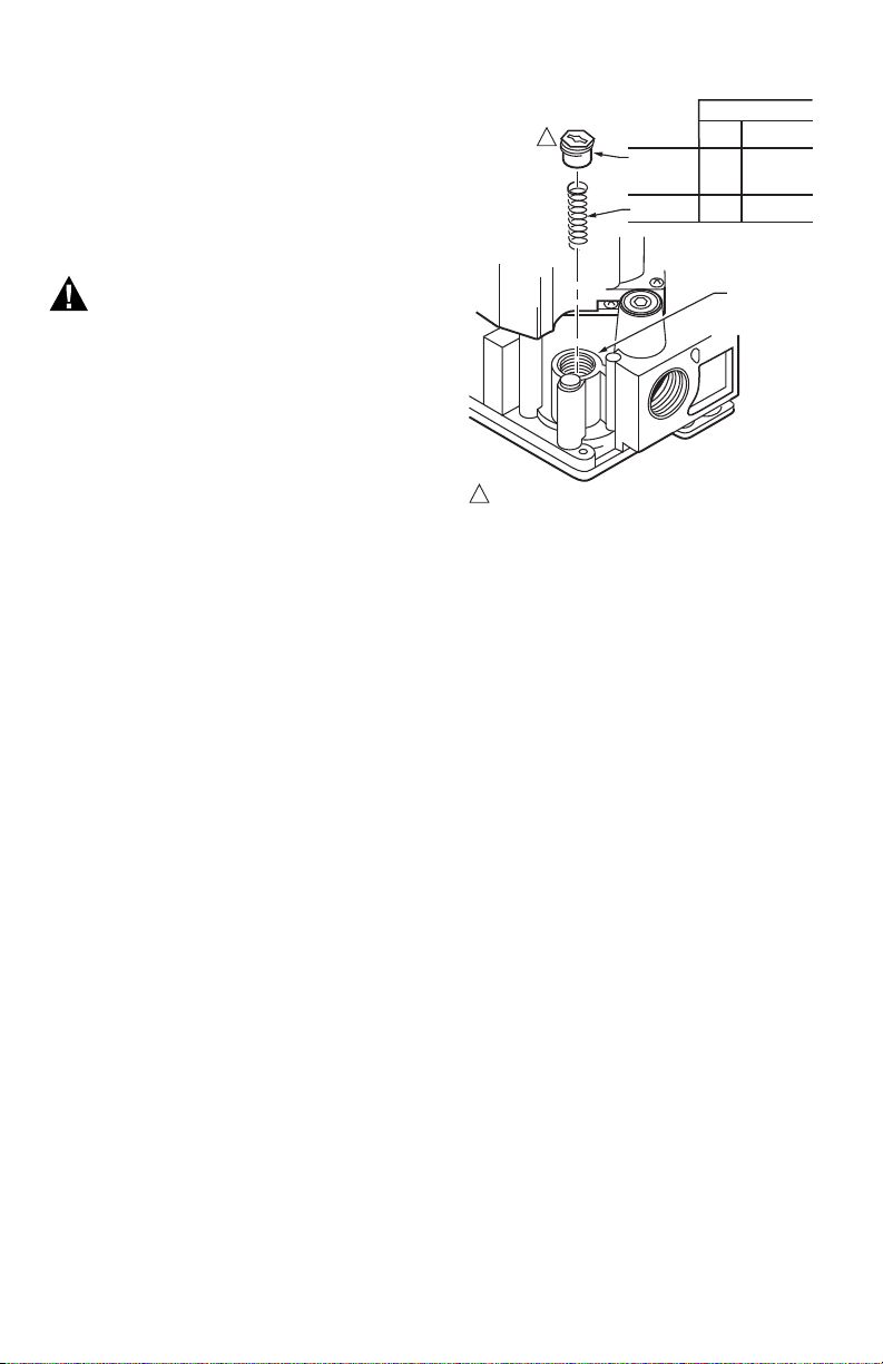
2. Remove regulator cap screw and save. See Fig. 5.
3. Remove the pressure regulator adjusting screw.
See Fig. 1.
4. Remove the existing spring.
5. Insert the replacement spring. See Fig. 1.
6. Install the new plastic pressure regulator adjust-
ment screw.
7. Check the regulator setting using a manometer
or by clocking the gas meter. See “Check and
Adjust Gas Input and Burner Ignition” on page 7.
8. Reinstall the regulator cap screw.
9. Mount conversion label on the gas control.
Fig. 1. Converting between LP and natural gas.
Install Bushings To Control
If bushings are being installed on the control, mount
them as follows:
Bushings
1. Remove the seal over the control inlet or outlet.
2. Apply a moderate amount of good quality pipe
compound to the bushing, leaving two end
threads bare. On an LP installation, use
compound that is resistant to LP gas. See Fig. 2.
NOTE: Do not use Teflon tape.
3. Insert the bushing in the control and carefully
thread the pipe into the bushing until tight.
Complete the instructions below for installing the
piping, installing the control, connecting the wiring.
Make sure the leak test you perform on the control
after completing the installation includes leak testing
the bushings.
Location
The gas controls are mounted in the appliance
vestibule on the gas manifold. If this is a replacement
application, mount the gas control in the same
location as the old control.
Locate the combination gas control where it cannot be
affected by steam cleaning, high humidity, or dripping
water, corrosive chemicals, dust or grease
accumulation or excessive heat.
To assure proper operation, follow these guidelines:
• Locate gas control in a well-ventilated area.
• Mount gas control high enough above cabinet
bottom to avoid exposure to flooding or splashing
water.
• Assure the ambient temperature does not exceed
the ambient temperature ratings for each
component.
COLOR CODE FOR
LP
GAS
NATURAL
GAS
PRESSURE
REGULATOR
ADJUSTING
SCREW
BLACK BLACK
SPRING
RED
STAINLESS
STEEL
PRESSURE
REGULATOR
HOUSING
M20046B
REUSE EXISTING METAL CAP SCREW.
1
1
VR8215S,T DIRECT IGNITION COMBINATION GAS CONTROLS
5 34-00006EF—03
• Cover gas control if appliance is cleaned with water,
steam, or chemicals or to avoid dust and grease
accumulation.
• Avoid locating gas control where exposure to
corrosive chemical fumes or dripping water are
likely.
Install Piping to Control
All piping must comply with local codes and
ordinances or with the National Fuel Gas Code (ANSI
Z223.1, NFPA No. 54), whichever applies. Tubing
installation must comply with approved standards
and practices.
1. Use new, properly reamed pipe that is free from
chips. If tubing is used, make sure the ends are
square, deburred and clean. All tubing bends
must be smooth and without deformation.
2. Run pipe or tubing to the control. If tubing is
used, obtain a tube-to-pipe coupling to connect
the tubing to the control.
3. Install a sediment trap in the supply line to the
control. See Fig. 3.
Install Control
1. Can be mounted in any direction.
2. Mount so the gas flow is in the direction of the
arrow on the bottom of the control.
NOTE: Gas valve will leak if installed backwards.
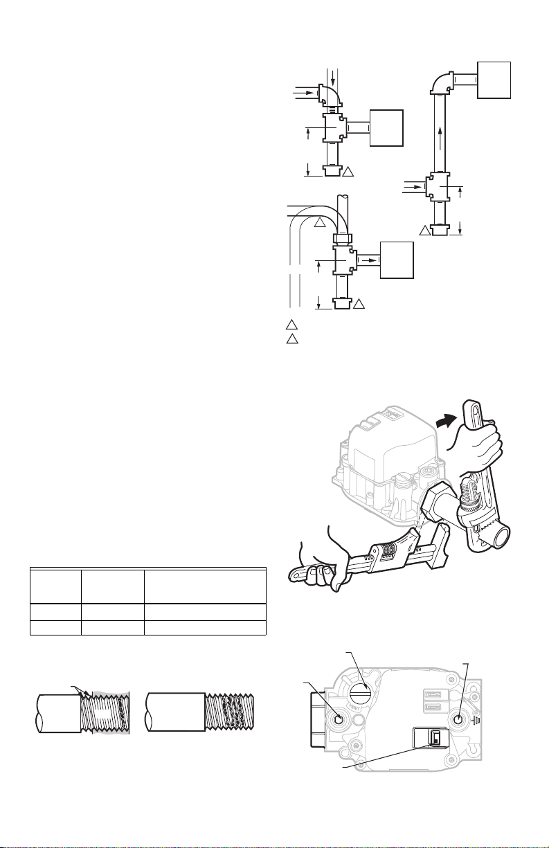
3. Thread the pipe the amount shown in Table 6 for
insertion into control or adapters. Do not thread
pipe too far. Valve distortion or malfunction can
result if the pipe is inserted too deeply.
4. Apply a moderate amount of good quality pipe
compound (do not use Teflon tape) only to the
pipe, leaving two end threads bare. On LP
installations, use a compound resistant to LP
gas. See Fig. 2.
5. Remove the seals over the control inlet and out-
let if necessary.
6. Connect the pipe to the control inlet and outlet.
Use a wrench on the hex end of the control. See
Fig. 4.
Table 6. NPT Pipe Thread Length.
a
a
All dimensions are in inches (mm).
b
OK when bushings are used.
Fig. 2. Use moderate amount of pipe compound.
Fig. 3. Sediment trap installation.
Fig. 4. Proper use of wrench on gas control.
Fig. 5. Top view of gas control.
Pipe
Size
Thread Pipe
this Amount
Maximum Depth Pipe
can be inserted into
Control
3/8
b
9/16 (14) 3/8 (9)
1/2 3/4 (19) 1/2 (13)
TWO IMPERFECT
THREADS
GAS CONTROL
THREAD PIPE THE AMOUNT
SHOWN IN TABLE FOR
INSERTION INTO GAS CONTROL
APPLY A MODERATE AMOUNT OF
PIPE COMPOUND TO PIPE ONLY
(LEAVE TWO END THREADS BARE).
M3075B
PIPE
GAS
CONTROL
GAS
CONTROL
HORIZONTAL
DROP
PIPED
GAS
SUPPLY
PIPED
GAS
SUPPLY
3 IN.
(76 MM)
MINIMUM
3 IN.
(76 MM)
MINIMUM
RISER
GAS
CONTROL
TUBING
GAS
SUPPLY
HORIZONTAL
DROP
3 IN.
(76 MM)
MINIMUM
RISER
M3077
2
1
2
2
1
2
ALL BENDS IN METALLIC TUBING SHOULD BE SMOOTH.
CAUTION: SHUT OFF THE MAIN GAS SUPPLY BEFORE REMOVING
END CAP TO PREVENT GAS FROM FILLING THE WORK AREA. TEST
FOR GAS LEAKAGE WHEN INSTALLATION IS COMPLETE.
M27669A
M27670B
ON
OFF
PRESSURE REGULATOR
ADJUSTMENT (UNDER
CAP SCREW)
INLET
INLET
PRESSURE
TAP 1/8 IN.
NPT
OUTLET
OUTLET
PRESSURE
TAP 1/8 IN.
NPT
ON/OFF SWITCH
VR8215S,T DIRECT IGNITION COMBINATION GAS CONTROLS
34-00006EF—03 6
Wiring
Follow the wiring instructions furnished by the
appliance manufacturer, if available, or use the
general instructions provided below. When these
instructions differ from the appliance manufacturer,
follow the appliance manufacturer instructions.
IMPORTANT
All wiring must comply with applicable electri-
cal codes and ordinances.
WARNING
Electrical Shock Hazard or Equipment
Damage Hazard.
Can cause serious injury, death or equipment
damage.
Disconnect power supply before making wiring
connections to prevent electrical shock or
equipment damage.
1. Check the power supply rating on the gas control
and make sure it matches the available supply.
Install a transformer and other controls as
required.
2. Connect the control circuit to the gas control
terminals. See Fig. 6 and 7.
3. Adjust thermostat heat anticipator to 0.50A rat-
ing stamped on valve label.
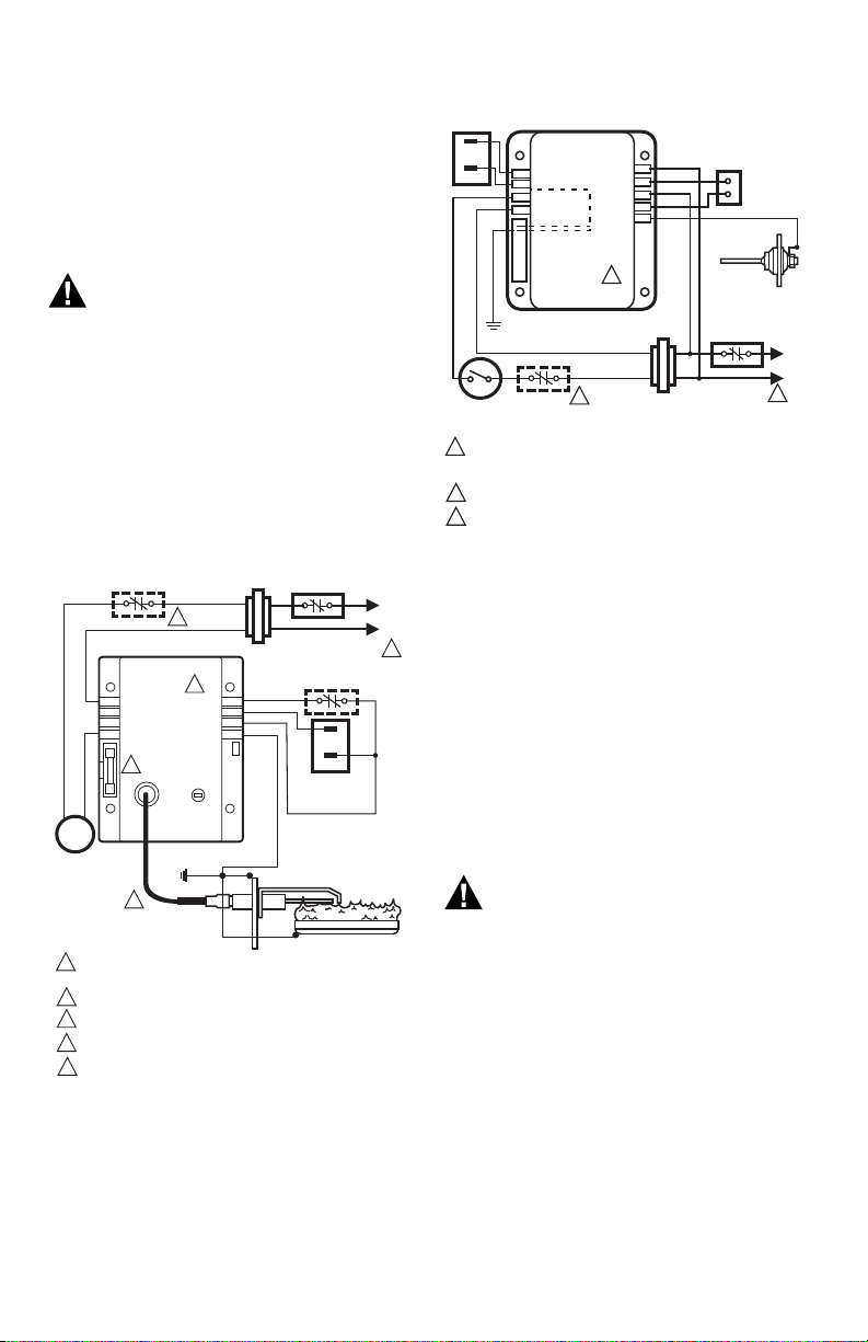
Fig. 6. Typical wiring connections for 24 volt
control in S87 Direct Ignition System.
Fig. 7. Typical wiring connections with 24 volt
control in S89 Direct Ignition System.
STARTUP AND CHECKOUT
On-Off Switch
The on-off switch settings are as follows:
• OFF: Prevents main gas flow through the control.
• ON: Permits gas to flow into the control body. Under
control of the thermostat and direct ignition
module, gas can flow to the main burners.
NOTE: Controls are shipped with the electronic on-
off switch in the ON position.
Perform Gas Leak Test
WARNING
Fire or Explosion Hazard.
Can cause property damage, severe injury
or death.
Perform Gas Leak Test every time work is done
on a gas system.
IMPORTANT
Do not spray soap and water solution on the
gas control. This can damage the control. Do
not use an excessive amount of soap and
water solution to perform the gas leak test.
Apply only to pipe thread areas.
Gas Leak Test
1. Paint pipe connections upstream of the gas con-
trol with rich soap and water solution. Bubbles
indicate a gas leak.
2. If a leak is detected, tighten the pipe connec-
tions.
24V
24V (GND)
S87B CONTROL MODULE
ALARM
VALV E
VALV E
GND
TEMPERATURE
CONTROLLER
POWER SUPPLY. PROVIDE DISCONNECT MEANS AND OVERLOAD
PROTECTION AS REQUIRED.
ALTERNATE LIMIT CONTROLLER LOCATION.
MAXIMUM IGNITER-SENSOR CABLE LENGTH: 3 ft. (0.9 m) OR LESS.
3A REPLACEABLE FUSE.
ALARM TERMINAL PROVIDED ON SOME MODELS.
M27697
L1
(HOT)
L2
1
2
1
2
3
DUAL VALVE
COMBINATION
GAS CONTROL
Q347 IGNITER-SENSOR
BURNER
4
4
5
IGNITER-SENSOR AND
BURNER GROUND
3
5
ALARM, IF USED
WHITE
BLUE
BLACK
BLUE
HOT
SURFACE
IGNITER-
SENSOR
VALV E
VALVE (GND)
24V
TH-W
24V (GND)
GND (BURNER)
S89C,G,J/S890C,G,J
HOT SURFACE
IGNITION CONTROL
L2
HSI
L1
HSI
LIMIT
CONTROLLER
BURNER
GROUND
THERMOSTAT
OR CONTROLLER
DUAL VALVE
COMBINATION
GAS CONTROL
POWER SUPPLY. PROVIDE DISCONNECT MEANS AND OVERLOAD
PROTECTION AS REQUIRED. MAKE SURE L1 AND L2 ARE NOT
REVERSED; THIS WOULD PREVENT FLAME DETECTION.
ALTERNATE LIMIT CONTROLLER LOCATION.
SEN TERMINAL AND Q354 FLAME SENSOR ON D MODELS ONLY.
M27628
L1
(HOT)
L2
VENT
DAMPER PLUG
1
2
1
2
3
3
SEN
Q354 FLAME
SENSOR
Loading...