


Honeywell W7752J, W7754P, W7752G, W7754K, W7752D SYSTEM ENGINEERING
...
|
Excel 10 |
|
|
W7752D,E,F,G,J AND W7754K,L,M,N,P |
|
|
FAN COIL UNIT CONTROLLERS |
|
|
SYSTEM ENGINEERING |
|
|
CONTENTS |
|
Revision overview ....................................................................................................................................................................... |
|
2 |
Introduction.................................................................................................................................................................................. |
|
3 |
|
Description of Devices.............................................................................................. |
3 |
|
Products Covered..................................................................................................... |
4 |
|
Organization of Manual............................................................................................. |
4 |
|
Applicable Literature................................................................................................. |
4 |
|
Product Names......................................................................................................... |
4 |
|
Control Application ................................................................................................... |
4 |
|
Control Provided....................................................................................................... |
5 |
|
Setpoints.............................................................................................................. |
6 |
|
Bypass ................................................................................................................. |
7 |
|
LED/LCD.............................................................................................................. |
7 |
|
Energy-Saving Features ...................................................................................... |
8 |
|
Occupancy Status................................................................................................ |
8 |
|
Safety Features.................................................................................................... |
9 |
|
Operating Modes ............................................................................................... |
10 |
|
Agency Listings ...................................................................................................... |
11 |
|
Construction ........................................................................................................... |
11 |
|
Excel 10 W7752 FCU Controllers...................................................................... |
11 |
|
Excel 10 W7754 FCU Controllers...................................................................... |
11 |
|
Controller Performance Specifications .............................................................. |
13 |
|
Configurations ........................................................................................................ |
14 |
|
General .............................................................................................................. |
14 |
|
Fan Type............................................................................................................ |
14 |
|
Type of Heating and Cooling Equipment ........................................................... |
15 |
|
Reheat Output.................................................................................................... |
16 |
|
Digital Input........................................................................................................ |
16 |
|
Excel 10 Wall Module Options........................................................................... |
17 |
|
Abbreviations and Definitions ................................................................................. |
18 |
|
Overview................................................................................................................. |
19 |
|
Step 1. Plan the System ......................................................................................... |
19 |
Application Steps ...................................................................................................................................................................... |
|
19 |
|
Step 2. Determine Other Bus Devices Required .................................................... |
19 |
|
Step 3. Lay Out Communications and Power Wiring ............................................. |
20 |
|
LONWORKS Layout.............................................................................................. |
20 |
|
Power Wiring ..................................................................................................... |
22 |
|
Step 4. Prepare Wiring Diagrams........................................................................... |
22 |
|
General Considerations ..................................................................................... |
22 |
|
Terminal Block Assignment and Wiring Example for the W7752 Controller...... |
23 |
|
Terminal Block Assignment and Wiring for the W7754 Controller..................... |
24 |
|
LONWORKS Termination ..................................................................................... |
25 |
|
Step 5. Order Equipment........................................................................................ |
26 |
|
Step 6. Configure Controllers ................................................................................. |
28 |
|
General .............................................................................................................. |
28 |
|
Output ................................................................................................................ |
29 |
|
Input................................................................................................................... |
30 |
|
Equipment Control ............................................................................................. |
31 |
|
Fan..................................................................................................................... |
31 |
|
Switching Levels ................................................................................................ |
32 |
|
Zone Options ..................................................................................................... |
32 |
® U.S. Registered Trademark |
|
|
Copyright © 2003 Honeywell Inc. • |
All Rights Reserved |
|
All Rights Reserved |
EN0B-0377GE51 R0703 (74-2961-5) |
|
EXCEL 10 FAN COIL UNIT CONTROLLER SYSTEM ENGINEERING |
|
Miscellaneous..................................................................................................... |
32 |
PID...................................................................................................................... |
33 |
Commissioning ................................................................................................... |
33 |
ID Number .......................................................................................................... |
33 |
Excel 10 FCU Controller Point Mapping ............................................................. |
33 |
Step 7. Troubleshooting .......................................................................................... |
35 |
Troubleshooting Excel 10 FCU Controllers and Wall Modules........................... |
35 |
Alarms ................................................................................................................ |
35 |
Broadcasting the Service Message .................................................................... |
37 |
Manual Mode ...................................................................................................... |
37 |
Appendix A. Using E-Vision to Commission a Fan Coil Unit ................................................................................................. |
38 |
Temperature Sensor Calibration ............................................................................. |
38 |
Procedure ........................................................................................................... |
38 |
Appendix B. Configuring for Master/Slave Operation............................................................................................................. |
39 |
Output Configuration Options.................................................................................. |
39 |
Input Configuration Options..................................................................................... |
39 |
Equipment Control Options ..................................................................................... |
39 |
Zone Control Options .............................................................................................. |
39 |
Network Variable Binding ........................................................................................ |
39 |
Appendix C. Complete List of Excel 10 FCU Controller User Addresses ............................................................................. |
41 |
Appendix D. Q7750A Excel 10 Zone Manager Point Estimating Guide ................................................................................. |
82 |
Approximate Memory Size Estimating Procedure ................................................... |
82 |
REVISION OVERVIEW |
|
On the following pages changes have been made compared to the previous release of this document: |
|
Page: Change: |
|
EN0B-0377GE51 R0703 |
2 |
EXCEL 10 FAN COIL UNIT CONTROLLER - SYSTEM ENGINEERING
INTRODUCTION
Description of Devices
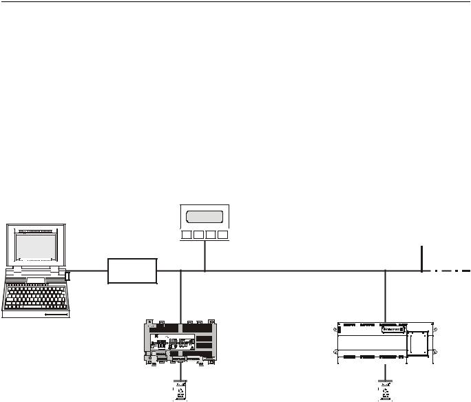
The W7752D,E,F,G,J and W7754K,L,M,N,P Fan Coil Unit (FCU) Controllers all belong to the Excel 10 family product line. FCU systems control the space temperature in a given room by regulating the heating and/or cooling equipment which control the temperature of the air delivered to that space and the fan which controls air flow. Reheat coils are often included at the fan coil unit. Excel 10 FCU controllers are capable of stand-alone operation; however, optimum functional benefits are achieved when the network communication capabilities are used.
The zone controlled by the Excel 10 FCU controllers will typically use an Excel 10 wall module with a temperature sensor for space temperature measurement, analog setpoint input, bypass push-button, and occupancy/unoccupancy override. See page 4 for form numbers of Excel 10 wall module literature for further information.
The Excel 500 can assume all of the Excel 10 FCU controllers' scheduling functions. The number of Excel 10 FCU controllers on the LONWORKS network is determined by the rules of LonWorks network design (see Table 10). Frontends can be either EBNI, SymmetriE, or SynOpsys, depending upon the size and complexity of the connected system.
Excel 500
PCLTA10
PCC10
Excel 10 W7754 |
+ - |
1 |
2 |
3 |
4 |
5 |
6 |
7 |
131415161718 192021222324 2526 |
|
|
|
|
|
|
|
|
|
0345 |
W7754Kxxxx |
Honeywell |
|
|
|
|
|
|
|
|
|
230 Vac, 50/60 Hz |
D-71101 Schönaich |
|
|
|
GND |
LED |
FAN |
DI2 |
|
|
max. 5 VA unloaded |
Made in Germany |
FCU Controller |
|
|
8 |
9 |
10 |
11 |
12 |
|
|
|
|
LON |
5 |
3 4 2 |
1 |
|
230 Vac |
||||
LonWorks network
Excel 10 W7752
FCU Controller
Excel 10 |
|
|
|
|
|
Excel 10 |
|
|
|
|
|
|
|
|
|
|
|
|
|
||
|
|
|
|
|
|
|
|
|
||
wall module |
|
|
|
|
|
wall module |
|
|
|
|
|
|
|
|
|
|
|
|
|
||
|
|
|
|
|
|
|
|
|
||
Fig. 1. Typical EXCEL 5000® System overview |
|
|
|
|
|
|||||
3 |
EN0B-0377GE51 R0703 |

EXCEL 10 FAN COIL UNIT CONTROLLER - SYSTEM ENGINEERING
Products Covered
This System Engineering Guide describes how to apply the Excel 10 FCU controller and the accessories to typical FCU applications. The specific devices covered include:
•W7752D,E,F,G, and J FCU Controllers.
•W7754K,L,M,N, and P FCU Controllers.
•T7460 Wall Modules.
•T7560 Wall Modules.
•for further products, see Appendices.
Organization of Manual
The Introduction and Application Steps 1 through 5 provide the information needed to make accurate ordering decisions. Application Step 6 and the Appendices include configuration engineering that can be started using E-Vision software after the devices and accessories are ordered. Application Step 7 is troubleshooting. Information provided in support of the use of third-party LONWORKS communication packages to configure FCU Controllers is found in the Appendices.
The organization of the manual assumes a project is being engineered from start to finish. If you are adding to or changing an existing system, the Table of Contents can guide you to the relevant information.
Applicable Literature
The following is a list of documents containing information related to the Excel 10 FCU Controller and the EXCEL 5000 System in general.
Form No. |
Title |
EN0B-0376GE51 |
Excel 10 W7752D,E,F,G,J FCU |
|
Controller Specification Data |
EN1B-0250GE51 |
Excel 10 W7752D,E,F,G,J FCU |
|
Controller Installation Instructions |
EN1B-0251GE51 |
Excel 10 W7754K,L,M,N,P FCU |
|
Controller Installation Instructions |
74-3083 |
Excel 10 T7460 Wall Modules |
|
Specification Data |
95-7610 |
Excel 10 T7460 Wall Modules |
|
Installation Instructions |
74-3097 |
Excel 10 T7560 Wall Modules |
|
Specification Data |
95-7620 |
Excel 10 T7560 Wall Modules |
|
Installation Instructions |
74-2950 |
Excel 10 Q7750A, Excel 10 Zone |
|
Manager Specification Data |
95-7509 |
Excel 10 Q7750A Zone Manager |
|
Installation Instructions. |
95-7554 |
Excel 10 FTT/LPT 209541B |
|
Termination Module Installation |
|
Instructions |
95-7510 |
Excel 10 Q7751A Router Installation |
|
Instructions (US only) |
95-7511 |
Excel 10 Q7752A Serial Interface |
|
Installation Instructions (US only) |
74-2588 |
Excel E-Vision User Guide |
74-5587 |
Excel CARE User Guide |
74-2039 |
XBS User’s Manual |
74-5018 |
XBS Application Guide |
Product Names
The W7752 Controller is available in five models:
•W7752D FCU Controller with 230 Vac power input and with reheat relay.
•W7752E FCU Controller with 230 Vac power input without reheat relay.
•W7752F FCU Controller with 115 Vac power input with reheat relay.
•W7752G FCU Controller with 115 Vac power input without reheat relay.
•W7752J FCU Controller with 100 Vac power input without reheat relay.
The W7754 Controller is available in five models:
•W7754K FCU Controller with 230 Vac power supply, one triac output, and one digital output for the low-voltage Pulse-Width Modulated (PWM) control of a solid-state relay employed in high-current electric reheat applications
•W7754L FCU Controller with 24 Vac power supply and two triac outputs
•W7754M FCU Controller with 230 Vac power supply
•W7754N FCU Controller with 230 Vac power supply and two triac outputs
•W7754P FCU Controller with 230 Vac power supply, four triac outputs, and an extra, fourth relay
The 2000-series FCU controllers can use any of the following Excel 10 wall modules:
•T7460A with temperature sensor.
•T7460B with temperature sensor and setpoint adjustment.
•T7460C with temperature sensor, setpoint adjustment, and bypass button and LED.
•T7460D with temperature sensor, setpoint adjustment and 5-position fan switch.
•T7460E with temperature sensor, setpoint adjustment, bypass button and LED, and 3-position fan switch.
•T7460F with temperature sensor, setpoint adjustment, bypass button and LED, and 5-position fan switch.
•T7560A with temperature sensor, unit enable button, setpoint adjustment, bypass button, LCD display and configurable fan override with up to five settings.
Other products:
•Q7750A Excel 10 Zone Manager.
•Q7751A Bus Router (US, only).
•Q7752A Serial Adapter (US, only).
•AK3781 LONWORKS (non-plenum): 22 AWG (0.325 mm2) twisted pair solid conductor, non-shielded wire (one twisted pair) (US, only).
•AK3782 LONWORKS (non-plenum): 22 AWG (0.325 mm2) twisted pair solid conductor, non-shielded wire (two twisted pairs) (US, only).
•AK3791 LONWORKS (plenum): 22 AWG (0.325 mm2) twisted pair solid conductor, non-shielded wire (one twisted pair) (US only).
•AK3792 LONWORKS (plenum): 22 AWG (0.325 mm2) twisted pair solid conductor, non-shielded wire (two twisted pairs) (US, only).
•C7608A Return Air Sensor (Europe, only).
Refer to the Table 15 (see section "Step 5. Order Equipment") for complete listing of all available part numbers.
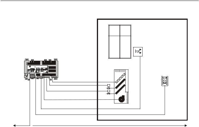
Control Application
FCU systems in commercial buildings control room temperature through the control of heat and/or cold water valves and fan speed. Electric reheat coils may also be used in the system. The FCU Controller is located in the fan coil unit and is typically connected to an Excel 10 wall module which incorporates a temperature sensor, setpoint and fan
EN0B-0377GE51 R0703 |
4 |
EXCEL 10 FAN COIL UNIT CONTROLLER SYSTEM ENGINEERING
speed controls, and a bypass or override button. Fig. 2 shows a typical FCU control application.
wall contact
Excel 10 W7754
FCU Controller
|
|
|
|
|
|
|
0345 |
W7754Kxxxx |
Honeywell |
||||
|
|
|
|
|
|
|
|
230 Vac, 50/60 Hz |
D-71101 Schönaich |
||||
|
|
|
GND |
LED |
FAN |
DI2 |
|
max. 5 VA unloaded |
Made in Germany |
|
|||
+ - |
|
|
|
|
|
|
triac |
|
|
||||
|
|
8 |
9 |
10 11 12 |
10A |
2 A |
|
0.5 A |
|
|
|||
|
1 |
2 |
3 |
4 |
5 |
6 |
7 |
131415161718 |
1920 21222324 |
2526 |
2A/M |
||
RS1A 23D25 |
|
|
DI1 |
SET |
SENS |
GND |
|
III |
II I |
close open |
close open com com |
230 V |
|
|
|
|
|
fan |
|
||||||||
|
|
|
|
|
|
|
|
|
|
|
|
N L |
|
|
LON |
|
T74605 3 4/ 2T75601 |
L |
|
|
OUT1 OUT2 |
|
|
||||
|
|
230 V N |
|
|
230 Vac |
|
|
||||||
Excel 10 wall module
LonWorks network
Fig. 2. Typical Excel 10 FCU control application
Control Provided
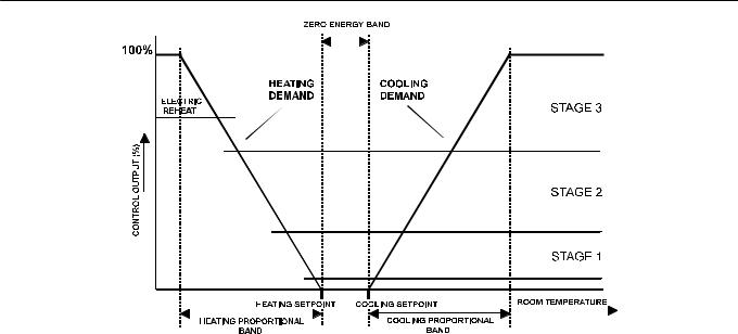
The Excel 10 FCU controllers provide room temperature control for twoand four-pipe fan coil units with optional electric heating coil. The basic control sequence is shown in Fig. 3. As space temperature falls below the heating setpoint, the heating output is increased. As space temperature increases above the cooling setpoint, the cooling output is modulated to 100%. Switching levels for staged heating/cooling and fan speeds are configurable. The fan may still be configured to run continuously during the zero energy band in the occupied mode. Additional configurable fan control features include fan min. ON and OFF times, run-up times, and overrun times.
The Excel 10 FCU controllers use a PID control algorithm with which each of the three parameters can be configured. There are additional configurable boost parameters (HeatBoost and CoolBoost) which specify a range outside of which the heating or cooling outputs are turned on fully for faster response (for thermal actuators this specifies the control hysteresis). The controllers are delivered with factory defaults for each of the parameters.
5 |
EN0B-0377GE51 R0703 |
EXCEL 10 FAN COIL UNIT CONTROLLER SYSTEM ENGINEERING
Fig. 3. Control sequence diagram
Setpoints
Setpoint Knob
The Excel 10 FCU controllers may be connected to an Excel 10 wall module equipped with a setpoint knob. When configured (UseWallModSpt), the value from the setpoint knob is used to calculate the "occupied" setpoint for the heating and the cooling modes. There are two options (SptKnob) which determine how the setpoint used by the control algorithm is calculated: "relative" (or "offset") and "absolute middle". When configured for "relative", the Excel 10 wall module setpoint knob represents a number from -9...+9 DDF(-5...+5 K) which is added to the configured "occupied" and "standby" setpoints for the heating and the cooling modes (SptCoolOcc and SptHeatOcc). When SptKnob is set to "absolute middle", the setpoint knob becomes the mid-point of the Zero Energy Band (ZEB) extending between the "occupied" or "standby" setpoints for the heating and the cooling modes. The range of the ZEB is found by taking the difference between the "occupied" or "standby" setpoints configured for the heating and the cooling modes; in the case of "absolute middle", the current "occupied" and "standby" setpoints are therefore found as follows:
"occupied" setpoint:
SrcRmTempSptEff (in cooling mode) = SrcRmTempSptHw + (SptCoolOcc - SptHeatOcc) / 2
SrcRmTempSptEff (in heating mode) = SrcRmTempSptHw - (SptCoolOcc - SptHeatOcc) / 2
"standby" setpoints:
SrcRmTempSptEff (in cooling mode) = SrcRmTempSptHw + (SptCoolStby - SptHeatStby) / 2
SrcRmTempSptEff (in heating mode) = SrcRmTempSptHw - (SptCoolStby - SptHeatStby) / 2
When in the "unoccupied" mode, the remote setpoint knob is ignored, and the configured setpoints for those modes are used instead.
SptKnobLowLim and SptKnobHiLim. In the case of absolute "occupied" and "standby" setpoints, the setpoint knob still represents the mid-point of the ZEB, even when set to either of these limits. The actual setpoints are given by the equations shown above. When the setpoint knob is configured to be "relative", the lowest actual "occupied" setpoint allowed is equal to SptHeatOcc - SptKnobLowLim, and the highest allowed is equal to SptCoolOcc + SptKnobHiLim. The lowest and highest "standby" setpoints are found in an analogous way.
Setpoint from Network
When not configured for UseWallModSpt, DestRmTempSpt must be bound to another node that provides a setpoint. When bound and when a valid update is received, DestRmTempSpt is used with the appropriate ZEB:
ZEBoccupied = SptCoolOcc - SptHeatOcc
ZEBstandby = SptCoolStby - SptHeatStby
The "unoccupied" setpoint does not depend on DestRmTempSpt at all.
Setpoint Offset
Third-party nodes may be bound to DestSptOffset in order to shift the setpoint in the range of -18...+18 DDF (-10...+10 K).
Setpoint Limits
Setpoints are limited to the range of 50...95°F (10...35°C). The value of the setpoint knob (SrcRmTempSptHw) is limited to the range provided by the configuration parameters
EN0B-0377GE51 R0703 |
6 |

EXCEL 10 FAN COIL UNIT CONTROLLER SYSTEM ENGINEERING
Table 1. Example setpoint values based upon default configuration – "absolute middle" setpoint knob (°C)
occupancy |
configured |
configured |
ZEB |
setpoint |
effective cooling |
effective heating |
mode |
cooling setpoint |
heating setpoint |
knob1 |
setpoint2,3 |
setpoint2,4 |
|
"occupied" |
23 |
21 |
2 |
21 |
22 |
20 |
"standby" |
25 |
19 |
6 |
21 |
24 |
18 |
"unoccupied" |
28 |
16 |
12 |
X |
28 |
16 |
NOTES:
1.Sample value shown. Limited by default configuration settings to the range of 12...30°C.
2.Limited to the range of 10...35°C.
3.= setpoint knob + (ZEB/2)
4.= setpoint knob – (ZEB/2)
Table 2. Example setpoint values based upon default configuration - Relative setpoint knob (°C)
occupancy |
configured |
configured |
ZEB |
setpoint |
effective cooling |
effective heating |
mode |
cooling setpoint |
heating setpoint |
knob1 |
setpoint2,3 |
setpoint2,4 |
|
"occupied" |
23 |
21 |
2 |
-2 |
21 |
19 |
"standby" |
25 |
19 |
6 |
-2 |
23 |
17 |
"unoccupied" |
28 |
16 |
12 |
X |
28 |
16 |
NOTES:
1.Sample value shown. Limited by default configuration settings to the range of -5...+5°C.
2.Limited to the range of 10...35°C.
3.= configured cooling setpoint + setpoint knob
4.= configured heating setpoint + setpoint knob
Bypass
Bypass Mode
During periods scheduled as being unoccupied, the Excel 10 wall module's bypass push-button may be used to force the FCU controller into the "occupied" mode. The FCU controller can also be forced into the "occupied" mode by means of a LONWORKS network command (DestManOcc set to OC_BYPASS). The controller will then remain in "bypass" mode until:
1.The bypass timer has timed out, or
2.The user again presses the Excel 10 wall module's bypass push-button, thus cancelling the "bypass" mode, or
3.The occupancy schedule (DestSchedOcc network input) switches the mode to "occupied".
4.The network input DestManOcc is set to OC_NUL.
The Excel 10 wall module indicates the current bypass mode status (see Excel 10 wall module literature for further information).
Bypass Timer
When the "bypass" mode has been activated, the bypass timer is set to BypTime (default of 180 minutes), at the end of which the mode will revert to its original state (see Excel 10 wall module literature for further information).
Continuous Unoccupied Mode
The "continuous unoccupied" mode is entered when an Excel 10 wall module is configured to allow it and if :
•(in the case of the T7460) the bypass button is pressed for four to seven seconds (until the LED blinks),
•(in the case of the T7560) the bypass button is pressed for more than five seconds (until the flashing moon appears).
The FCU controller can also be forced into the "continuous unoccupied" mode by means of a LONWORKS network command (DestManOcc set to OC_UNOCCUPIED). The FCU controller will then remain in this mode indefinitely, or until the bypass button is pressed to exit the mode or a network command is sent to clear the mode.
Bypass Push-Button
The FCU Controller may be connected to an Excel 10 wall module equipped with a bypass push-button. There are three ways to configure the bypass push-button (see Table 17 for further information):
NONE
BYPASS_UNOCCUPIED
BYPASS_ONLY
Override Priority
The FCU Controller can be configured to arbitrate overrides coming from the bypass push-button and the LONWORKS network. There are two possible states which have the following meanings:
LAST_WINS specifies that the last command received from either the wall module or DestManOcc determines the effective override state.
NETWORK_WINS specifies that when DestManOcc is not OC_NUL, then the effective occupancy mode is determined by DestManOcc regardless of the wall module override state.
LED/LCD
LED Override
The wall module’s LED indicates that the FCU controller is being overridden by either the bypass button or the
LONWORKS network.
• LED ON "override bypass"
7 |
EN0B-0377GE51 R0703 |
EXCEL 10 FAN COIL UNIT CONTROLLER SYSTEM ENGINEERING
• |
One flash per second |
"override unoccupied" |
• |
Two flashes per second |
"override standby" or |
|
"occupied" |
|
• |
LED OFF no override |
|
• |
Four flashes per second |
The controller is responding |
to a LONWORKS network management wink command.
LED Occupancy
The wall module’s LED indicates the effective occupancy mode.
• |
LED ON |
effective "occupied" or effective "bypass" |
|
• |
One flash per second |
effective "standby" |
|
• |
LED OFF |
effective "unoccupied" |
|
• |
Four flashes per second |
The controller is responding |
|
to a LONWORKS network management wink command.
LCD Display
This mode is used only for T7560 Wall Modules. The occupancy mode is represented by the following symbols:
effective "occupied" or effective "bypass"
effective "standby"
effective "unoccupied" Controller is OFF
and |
Controller is OFF, frost protection is enabled. |
Flashing symbols indicate the "override" mode: 


 override "occupied" or override "bypass"
override "standby"
override "unoccupied"
The controller is responding to a LONWORKS network management wink command.
Energy-Saving Features
The "Standby" Mode
The digital input for reading input from an occupancy sensor (usually a motion detector) provides the FCU controller with a means to enter an energy-saving standby mode whenever there are no people in the room. The "standby" mode occurs when the scheduled occupancy mode is "occupied" but the occupancy sensor indicates that the room is nevertheless currently unoccupied. If no occupancy sensor is directly connected to the FCU controller, an occupancy sensor from another node may be bound to the network input DestOccSensor. The FCU controller can also be forced into the "standby" mode by means of a LONWORKS network command (DestManOcc set to OC_STANDBY). When in the "standby" mode, the FCU Controller uses the "standby" setpoints configured for the heating and the cooling modes (SptHeatStby or SptCoolStby).
Window Sensor
The digital input for reading input from a window contact provides the FCU controller with a means to disable its temperature control activities if someone has opened a window or door in the room. If no window sensor is directly connected to the FCU controller, the sensor from another node may be
used by binding it to DestWindow. Frost protection remains active. Normal temperature control resumes when the window closes.
Demand Limit Control
When a high-electrical-demand signal is received from an energy management system via the LONWORKS network (DestDlcShed), the FCU controller uses DlcStptBump to shift the current setpoint (down for heating and up for cooling) by the configured value to save energy.
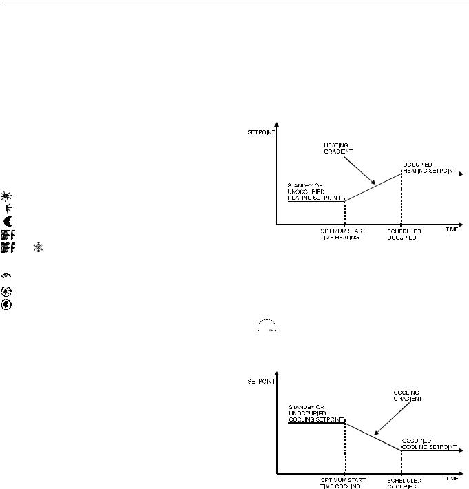
Fig. 4. Optimum start (heating)
Optimum Start Gradients
There are two parameters, RecRampCool and RecRampHeat, that can be configured to cause the cooling and heating setpoints respectively to ramp up to their occupied settings from their unoccupied or standby settings
prior to scheduled occupancy. The FCU controller


 uses the configured rates to determine the optimum


 time to start increasing the heating or cooling
demand. See the following figures. The configuration parameters are in K/hour.
Fig. 5. Optimum start (cooling)
Occupancy Status
The occupancy status is determined based upon Table 3. Manual override may come from the network input DestManOcc or from the bypass push-button.
EN0B-0377GE51 R0703 |
8 |

EXCEL 10 FAN COIL UNIT CONTROLLER SYSTEM ENGINEERING
Table 3. Effective Occupancy Mode Arbitration
scheduled occupancy mode |
occupancy sensor status |
manual override status |
effective operating mode |
"occupied" |
room occupied |
not assigned |
OC_OCCUPIED |
"occupied" |
room not occupied |
not assigned |
OC_STANDBY |
X |
X |
"occupied" |
OC_OCCUPIED |
X |
X |
"unoccupied" |
OC_UNOCCUPIED |
X |
X |
"standby" |
OC_STANDBY |
"occupied" |
X |
"standby" |
OC_OCCUPIED |
"standby" |
X |
not assigned |
OC_STANDBY |
"standby" |
X |
"standby" |
OC_OCCUPIED |
"unoccupied" |
X |
not assigned |
OC_UNOCCUPIED |
"unoccupied" |
X |
"standby" |
OC_BYPASS |
X=Don't care |
|
|
|
Safety Features
Frost Protection
If the room temperature falls below 46.4°F (8°C), the FCU controller enables the heating circuit to ensure frost protection and an alarm is issued. When the temperature rises above 48.2°F (9°C) again, the heating circuit is turned OFF again.
Smoke Control
The FCU controller will respond to LONWORKS network emergency commands by switching OFF heating/cooling outputs and switching OFF the fan (depressurize) or switching ON the fan at its highest speed (pressurize). An alarm is issued for any emergency commands
Fan Failure Protection
When configured with an airflow detector, the FCU controller protects equipment by switching OFF heating / cooling outputs and issuing an alarm when the fan fails.
Fan Interlocks
The FCU controller can be configured such that heating and/or cooling outputs are never ON unless the fan is running. A fan run-up time can be configured to turn ON the fan prior to the heating/cooling outputs being switched ON, and a fan overrun time can be configured to keep the fan running for a period of time after the heating/cooling outputs are switched OFF.
9 |
EN0B-0377GE51 R0703 |

EXCEL 10 FAN COIL UNIT CONTROLLER SYSTEM ENGINEERING
Operating Modes
The possible modes of operation are listed in Table 4.
Table 4. Modes of Operation for Excel 10 FCU Controller
mode |
description |
events causing a controller to switch to this mode |
operational modes (user address: SrcFcuModeS) |
|
|
START-UP AND |
Control algorithms are disabled. |
This is the first mode after an application restart. |
WAIT |
Outputs stay in their initial positions. |
|
|
Physical inputs are periodically read |
|
|
and digital filtering of analog inputs is |
|
|
turned OFF to speed up settling time. |
|
|
Input NVs are received and output |
|
|
NVs are sent periodically. |
|
FLOATING |
The FCU controller drives the floating |
When the effective occupancy changes to "unoccupied" or |
OUTPUTS SYNCH |
control valves to their initial positions |
"standby", after start-up, after 24 hours since the last positioning, |
|
and then transitions to one of the |
or after each positioning to 0%, the FCU controller transitions to |
|
control modes. |
this mode. |
COOLING |
The FCU controller is controlling in |
Input NV (DestHvacMode) has a value of HVAC_COOL or |
|
the cooling mode. |
HVAC_AUTO and the space temperature is above the cooling |
|
|
setpoint. |
HEATING |
The FCU controller is controlling in |
Input NV (DestHvacMode) has the value of HVAC_HEAT or |
|
the heating mode. |
HVAC_AUTO and the space temperature is below the heating |
|
|
setpoint. |
MANUAL MODE |
The control algorithms stay active |
Input NV (DestManMode) has value of MODE_MANUAL. |
|
and outputs are controlled auto- |
|
|
matically until set individually to test |
|
|
positions using the network input |
|
|
nviTest. |
|
FACTORY TEST |
Control algorithm is disabled; a |
This mode is for factory testing, only. |
|
special factory test program runs. |
|
DISABLED |
Control algorithms are terminated, |
Input NV (DestManMode) has a value of MODE_DISABLED. |
|
outputs are turned OFF (turn-OFF |
|
|
sequences and interlocks are active). |
|
|
Frost protection is disabled. |
|
PRESSURIZE |
Heating/cooling outputs are switched |
Input NV (DestEmerg) containing smoke control signal from C- |
|
OFF, and the fan is switched ON at |
Bus has the value of EMERG_PRESSURIZE. |
|
its highest speed. |
|
DEPRESSURIZE |
Heating, cooling and fan outputs are |
Input NV (DestEmerg) containing smoke control signal from C- |
|
switched OFF. |
Bus has the value of EMERG_DEPRESSURIZE. |
EN0B-0377GE51 R0703 |
10 |
EXCEL 10 FAN COIL UNIT CONTROLLER SYSTEM ENGINEERING
Agency Listings
Table 5 provides information on agency listings for Excel 10 FCU Controller products.
Table 5. Agency listings
device |
agency |
|
comments |
W7752D to J |
CE |
General Immunity per European Consortium standards EN50081-1 (CISPR 22 |
|
FCU Controller |
|
Class B) and EN 50082-1:1992 (based on Residential, Commercial, and Light |
|
|
|
Industrial). |
|
|
|
EN 61000-4-2 |
IEC 1000-4-2 (IEC 801-2) Electromagnetic Discharge. |
|
|
EN 50140, EN 50204 IEC 1000-4-3 (IEC 801-3) Radiated Electromagnetic Field. |
|
|
|
EN 61000-4-4 |
IEC 1000-4-4 (IEC 801-4) Electrical Fast Transient (Burst). |
|
|
Radiated Emissions and Conducted Emissions. |
|
|
|
EN 55022:1987 Class B. |
|
|
|
CISPR-22: 1985. |
|
W7752D to J |
FCC |
Complies with requirements in FCC Part 15 rules for a Class B Computing |
|
FCU Controller |
|
Device. |
|
W7752D to G |
UL |
Tested and listed under UL 916 (file number E87744). |
|
FCU Controller |
|
Ambient Temperature Rating: 32...122 °F (0...50 °C). |
|
W7752D to G |
cUL |
Tested and listed under UL 916 (file number E87744). |
|
FCU Controller |
|
Ambient Temperature Rating: 32...122 °F (0...50 °C). |
|
W7754K FCU Controller |
??? |
??? |
|
W7754L FCU Controller |
??? |
??? |
|
W7754M FCU Controller |
??? |
??? |
|
W7754N FCU Controller |
??? |
??? |
|
W7754P FCU Controller |
??? |
??? |
|
Construction
Excel 10 W7752 FCU Controllers
The Excel 10 W7752 FCU Controller is available in five basic models, each with two different possibilities for LONWORKS transceivers. All of these controllers are mains-powered, and two models are equipped with an additional high-power relay for applications with electric reheat. Table 6 shows the differences between models.
Table 6. Excel 10 W7752 FCU Controller models
OS number |
Power input |
Reheat relay |
W7752D2007 |
230 Vac |
X |
W7752E2004 |
230 Vac |
|
W7752F2002 |
115 Vac |
X |
W7752G2000 |
115 Vac |
|
W7752J2003 |
100 Vac |
|
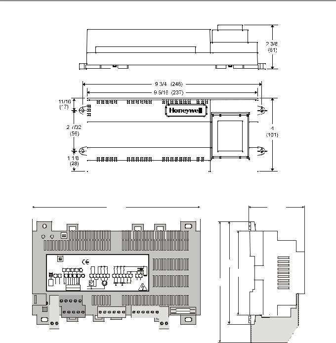
All wiring connections to the controllers are made at screw terminal blocks accessible beneath a plastic safety cover. Mounting dimensions are shown in Fig. 6.
Excel 10 W7754 FCU Controllers
The Excel 10 W7754 FCU Controller is available in five basic models, each with two different possibilities for LONWORKS transceivers. Table 7 shows the differences between models.
Table 7. Excel 10 W7754 FCU Controller models
OS number |
Power input |
Reheat relay |
W7754K1001 |
230 Vac |
X |
W7754L1009 |
24 Vac |
|
W7754M1007 |
230 Vac |
|
W7754N1004 |
230 Vac |
|
W7754P1000 |
230 Vac |
|
 CAUTION
If FCU Controllers are mounted vertically and thermal actuators are used, the transformer must not be located below the electronics due to heating effects.
 WARNING
Electrical Shock Hazard.
Mains power at terminal block can cause personal injury or death. FCU Controllers must be mounted inside their fan coil unit boxes to prevent access by unauthorized personnel.
To reduce the risk of fire or electric shock, install in a controlled environment relatively free of contaminants.
11 |
EN0B-0377GE51 R0703 |
EXCEL 10 FAN COIL UNIT CONTROLLER SYSTEM ENGINEERING
Fig. 6. W7752 construction in inches (mm)
180 |
59.5 |
WALL MOD. |
ON |
DI2 |
|
|
|
0345 |
W7754Kxxxx |
Honeywell |
|
||||||
UNUSED |
UNUSED |
|
|
|
|
|
|
|
|
|
|
|
|||
USED |
|
USED |
|
|
|
|
230 Vac, 50/60 Hz |
D-71101 Schönaich |
110 |
||||||
|
|
|
GND |
LED |
FAN DI2 |
|
|
max. 5 VA unloaded |
Made in Germany |
||||||
|
|
|
|
|
|
|
|
|
triac |
|
|||||
+ - |
|
|
8 |
9 |
10 |
11 12 |
|
10A |
2 A |
|
|
0.5 A |
|
90 |
|
|
|
|
|
|
|
|
|
|
|
|
|||||
1 |
2 |
3 4 5 |
6 |
7 |
|
131415161718 192021222324 |
2526 2A/M |
||||||||
|
|
||||||||||||||
RS1A 23D25 |
|
|
DI1 |
SET |
SENS |
GND |
|
L |
III |
II |
I |
close open |
close open com com |
N L |
130 |
|
|
|
|
fan |
|
||||||||||
|
|
|
|
|
|
|
|
|
|
|
|
|
|
230 V |
|
|
LON |
|
5 3 4 2 |
1 |
230 V |
N |
|
|
|
OUT1 OUT2 |
|
|
|||
|
|
|
|
T7460 / T7560 |
|
|
|
|
230 Vac |
|
|
||||
|
|
|
|
|
|
|
|
|
|
|
|
|
|
|
terminal protection |
|
|
|
|
|
|
|
|
|
|
|
|
|
|
|
cover (optional) |
Fig. 7. "7754 dimensions (in mm)
EN0B-0377GE51 R0703 |
12 |
EXCEL 10 FAN COIL UNIT CONTROLLER SYSTEM ENGINEERING
Controller Performance Specifications
Power:
W7752D and W7752E; W7754K,M,N,P
230 Vac +10%, -15%, 50/60 Hz.
W7752F and W7752G
115 Vac +10%, -15%, 50/60 Hz.
W7752J
100 Vac ±6%, 50/60 Hz.
W7754L
24 Vac ±20%, 50/60 Hz.
Operating Temperature:
32...122°F (0...50°C).
Shipping/Storage Temperature:
-40...+158°F (-40...+70°C).
Relative Humidity:
5% to 95% non-condensing
Inputs:
Temperature Sensor:
20k ohm NTC
Setpoint Potentiometer:
10k ohm
Digital Input:
Closed ≤ 400 ohms
Open ≥ 10 K ohms
Outputs:
Triac voltage range: 24 Vac ± 20%.
Triac max. current ratings: 250 mA continuous
650 mA surge for 30 sec.
IMPORTANT:
When any device is energized by a Triac, the device must be able to sink a minimum of 15 mA. If nonHoneywell motors, actuators, or transducers are to be used with Excel 10 FCU Controllers, compatibility must be verified.
Fan relays voltage range: 20 to 253 Vac
Fan relays max. current rating: 3 A
Electric reheat relay voltage range: 20 to 253 Vac
Electric reheat relay max. current rating: 10 A
6 A (UL916)
Interoperability
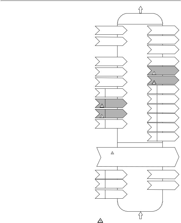
The W7752 Controllers use the LonTalk protocol. They support the LONMARK Functional Profile # 8020 “Fan Coil Unit Controller”, version 2.0. Fig. 8 shows the implementation used.
Hardware
Output
Fan Coil Unit Controller
Object #8020
nv1 |
|
nviSpaceTemp |
|
nv3 |
|
nvoHeatOutput |
|||
|
SNVT_temp_p |
|
|
SNVT_lev_percent |
|||||
|
|
Mandatory |
|
|
|
||||
|
|
|
|
|
|
|
|
|
|
|
|
|
|
|
|
|
|
|
|
|
|
nviSetPoint |
Network |
nv4 |
|
nvoCoolOutput |
|||
|
|
|
|||||||
nv2 |
|
Variables |
|
SNVT_lev_percent |
|||||
|
SNVT_temp_p |
|
|
|
|||||
|
|
|
|
|
|
|
|
||
|
|
|
|
|
nv5 |
|
nvoFanSpeed |
||
|
|
|
|
|
|
||||
|
|
|
|
|
|
||||
|
|
|
|
|
|
SNVT_switch |
|||
|
|
|
|
|
|
|
|
||
|
|
|
|
|
|
|
|
|
|
|
|
|
|
|
|
|
|
|
|
nv6 |
|
nviFanSpeedCmd |
|
nv11 |
|
|
nvoTerminalLoad |
||
|
|
|
|
||||||
|
SNVT_switch |
|
|
|
SNVT_lev_percent |
||||
|
|
nviOccCmd |
|
|
|
|
nvoLoadAbs |
||
|
|
|
nv12 |
|
|||||
|
|
|
|
||||||
nv7 |
|
|
|
SNVT_power |
|||||
|
|
SNVT_occupancy |
Optional |
|
|
|
|
|
|
|
|
|
|
|
|
|
nvoDischAirTemp |
||
|
|
|
|
|
|
|
|||
|
|
nviApplicMode |
Network |
nv13 |
|
||||
nv8 |
|
|
SNVT_temp_p |
||||||
|
SNVT_hvac_mode |
Variables |
|
|
|
|
|
||
|
|
|
|
|
|
|
|
|
|
nvoReheat
nviSetPtOffset nv14 SNVT_switch nv9 SNVT_temp_p
nvoSpaceTemp nv15 SNVT_temp_p
nviWaterTemp nv10 SNVT_temp_p
nvoEffectSetPt
nv16 SNVT_temp_p
nviDischAirTemp nv17 SNVT_temp_p
nv19 nvoEffectOcc
SNVT_occupancy
nviEnergyHoldOff
nv18 SNVT_switch nv20 nvoEnergyHoldOff SNVT_switch
nv21 |
nvoUnitStatus |
SNVT_hvac_status |
Configuration Properties
|
nc49 - nciSndHrtBt |
SNVT_time_sec |
mandatory |
|||||
|
nc52 - nciMinOutTm |
SNVT_time_sec |
optional |
|
||||
|
nc48 - nciRcvHrtBt |
SNVT_time_sec |
optional |
|
||||
|
nc17 - nciLocation |
SNVT_str_asc |
optional |
|||||
|
nc60 - nciSetPnts |
SNVT_temp_setpt |
mandatory |
|||||
|
nc59 - nciNumValve |
SNVT_count |
optional |
|||||
|
|
|
|
|
|
|
|
|
nviSensorOcc |
Manufacturer |
|
nvoSensorOcc |
|||||
|
||||||||
SNVT_Occupancy |
Defined |
|
SNVT_occupancy |
|||||
nviEmerg |
Section |
|
nvoDigitInState |
|||||
|
||||||||
|
|
|
||||||
SNVT_hvac_emerg |
|
|
|
|||||
|
|
|
SNVT_switch |
|||||
|
|
|
|
|
|
|||
nviReheatRelay |
|
|
|
|
|
|
||
|
|
|
|
|
|
|||
SNVT_switch |
|
|
|
|
|
|
||
Hardware
Input
NOT SUPPORTED.
Fig. 8. LONMARK FCU object profile
13 |
EN0B-0377GE51 R0703 |

EXCEL 10 FAN COIL UNIT CONTROLLER SYSTEM ENGINEERING
Configurations
General
The following sections provide an overview of the Excel 10 FCU Controller options related to inputs and outputs. See section "Step 6. Configure Controllers" (page 28) for a complete list of configuration options and defaults.
Table 8. Hardware options summary |
|
|
|
option |
possible configurations |
fan type |
no fan |
|
one-speed |
|
two-speed |
|
three-speed |
fan interlock |
enabled |
|
disabled |
FCU system type |
two-pipe |
|
four-pipe |
output 1 actuator type |
floating |
|
floating mid (one for heat/cool)1 |
|
one-stage |
|
two-stage |
|
three-stage |
|
PWM |
|
thermal |
output 2 actuator type |
floating |
|
floating mid (one for heat/cool)1 |
|
one-stage |
|
two-stage |
|
three-stage |
|
PWM |
|
thermal |
valve direction |
direct |
|
reverse |
reheat |
none |
|
reheat (W7752D and F only) |
|
free use (W7752D and F only) |
|
W7754? |
digital input |
not used |
|
window closed |
|
occupied sensor |
|
air flow detector |
|
cool changeover |
|
window open |
|
unoccupied sensor |
|
no air flow |
|
heat changeover |
|
movement |
|
no movement |
wall module option |
local |
|
shared |
temperature sensor |
none |
type |
NTC non-linearized |
NOTE:
1The floating-mid option is only for changeover applications and uses only one of the two outputs.
Fan Type
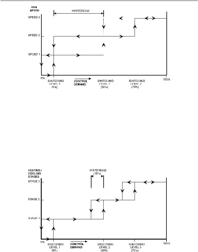
Each fan coil unit controlled by an FCU controller can have a fan with up to three different speeds or no fan at all. Multispeed fans are switched at the same switching levels as multi-staged heating control points (see Fig. 9). For example, a three-speed fan will switch ON its first speed at the same control level as the first stage of heating or cooling up until the second stage of heating or cooling where the second fan speed will switch ON. A two-stage fan will switch with the first two stages of a 3-stage heating or cooling system. Likewise, a single-speed fan will turn ON at the first stage of any multistaged system. Conversely, a multi-speed fan may follow multiple switching levels even for single-staged, floating, PWM, or thermal actuator-based systems.
Hysteresis
The hysteresis for fan speed extends to the next lower switching level (or a control level of 0) as is shown in Fig. 9. For example, the second fan speed will remain ON until the control level falls below the switching point for the first fan speed. Min. ON and OFF times can be configured and will apply to all fan switching points.
Interlock
A fan interlock can be configured which prevents heating or cooling outputs from being turned ON in the event of a fan failure (where an air flow detector is installed to detect fan failure). When fan interlock is configured, run-up and overrun times can be configured to delay switching ON the heating or cooling equipment after switching ON the fan and delay switching OFF the fan after the heating or cooling equipment is switched OFF.
The fan can be configured to run continuously during the zero energy band during occupied periods.
EN0B-0377GE51 R0703 |
14 |
EXCEL 10 FAN COIL UNIT CONTROLLER SYSTEM ENGINEERING
Fig. 9. Three-speed fan switching and hysteresis, cooling mode (defaults for switching levels shown)
Type of Heating and Cooling Equipment
The FCU controller can operate with either two-pipe or fourpipe systems. A two-pipe system requires a changeover input to the controller (hardware or network input).
The FCU controller can operate with a variety of actuators for heating and cooling equipment. Floating actuators can be used which will require specifying the valve run time during configuration of the controller. Valve action can be configured as either direct or reverse. When in a two-pipe system with a changeover input, a floating actuator can be used which has the middle position (50%) as the zero energy position. The cool range is then 0 to 50% and the heat range 50 to 100%. The output must be configured as floating-mid.
Multi-stage systems can be controlled with up to three different stages of heating/cooling control. Switching levels are specified in % of control level (see Fig. 10) as is a hysteresis setting which applies to all switching levels. Heating and cooling switching levels and hysteresis are specified separately. Min. OFF times can be configured, and for one-, twoand three-stage systems, a min. ON time can also be configured.
PWM electronic valves and thermal actuators can also be connected and can be configured as either direct or reverse action. The cycle time must be specified during configuration. In the case of PWM valves, the zero and full positions must also be configured.
Fig. 10. Three-stage heating/cooling switching (defaults for switching levels and hysteresis shown)
15 |
EN0B-0377GE51 R0703 |
EXCEL 10 FAN COIL UNIT CONTROLLER SYSTEM ENGINEERING
Reheat Output
W7752D and F Controllers have an additional high-current of 10 A max. (UL916: 6 A max.) output relay to control an electric reheater (refer to Fig. 2 for sample application). The reheat output has its own switching level and hysteresis settings (see Fig. 11). The reheat relay may also be used as an auxiliary output for other purposes, in which case the W7752 must be configured to specify that the output is under the control of the LONWORKS network, and not of the FCU control algorithm.
Fig. 11. Reheat switching and hysteresis (defaults shown)
Digital Input
There is a single digital input in the W7752 Controller which may be configured to accommodate an occupancy sensor, a window open/closed contact, an air flow detector (for fan failure detection), or a changeover input. It is possible to configure this input for either normally-open or normallyclosed contacts for any of the switches.
The control algorithm in the Excel 10 FCU controller uses the occupancy sensor, if configured, to determine the effective occupancy mode (see Table 3). If the Time Of Day (TOD)
schedule indicates an occupied state, and the eccupancy sensor contact is closed, the effective occupancy mode will be "occupied". However, if the TOD schedule indicates an occupied state and the occupancy sensor contact is open, then the effective occupancy mode will be "standby". The control algorithm will then control according to the "standby" setpoints configured for the heating and the cooling modes.
Configuring the digital input for movement or no movement (dependent upon normally-open or normally-closed contacts) adds a delay of 15 minutes to the occupancy sensor such that the space is considered occupied until 15 minutes has elapsed since the last movement is detected.
If the digital input is configured to read input from a window open/closed contact, heating, cooling, and fan control will be disabled while the window is detected open. Frost protection will be enabled. A set of contacts may be wired in series for multiple windows. If the window open/closed contact is not configured, a one-to-one association (binding) of the window sensor from another controller on the LONWORKS network can be made. A locally-wired contact can also be used in combination with the network input, the result being a logical OR of the inputs.
If the digital input is configured to read input from an air flow detector (fan status), heating and cooling control will be disabled for a fan failure (fan ON and no air flow detected).
The input may also be configured for changeover for a twopipe system.
NOTE: The Excel 10 FCU Controller has limited power available (only 1.5 mA/4.8 V) for checking the digital input for contact closures. Ensure that contacts used remain within the specified resistance tolerance range (closed ≤ 400 ohms) even when aged.
EN0B-0377GE51 R0703 |
16 |

EXCEL 10 FAN COIL UNIT CONTROLLER SYSTEM ENGINEERING
Excel 10 Wall Module Options
A typical FCU installation will include an Excel 10 wall module containing a 20k ohm NTC room temperature sensor and additional features depending on the wall module type (see Excel 10 wall module literature for further information).
The FCU controller can use a return air sensor rather than the sensor in the wall module if it is wired to the wall module sensor input. Setpoint adjustments can be configured as relative or absolute, and upper and lower limits can be set. A configuration option for the fan speed switch allows it to be disabled if not required. The bypass button can be configured to override the control mode to "occupied" for a configurable bypass time and to override the control mode to "unoccupied" for an indefinite time, or it may be configured to only override to "occupied". The button may also be used to cancel the override.
Common Temperature Control (Master/Slave Controllers)
When one or more FCU controllers serve a common area and a single temperature sensor is to be used, a master/slave arrangement can be configured. One Excel 10 FCU Controller is configured for the local wall module with the desired options. The other Excel 10 FCU Controller(s) will be configured without wall modules and with certain network variables bound with the master controller. Refer to Application Step 6 of this document for more details.
IMPORTANT
The slave units must have the same HVAC equipment connected to it as the master units.
The slave units will not use any internal temperature setpoints or control algorithms. The master controller determines heating/cooling output based upon setpoints and occupancy and LONWORKS network command mode status and communicates this to the slave via the LONWORKS network.
17 |
EN0B-0377GE51 R0703 |

EXCEL 10 FAN COIL UNIT CONTROLLER SYSTEM ENGINEERING
Abbreviations and Definitions
CARE Computer Aided Regulation Engineering;
the PC based tool used to configure C-Bus-
Bus devices.
C-Bus Honeywell proprietary Control Bus for communications between EXCEL 5000® System controllers and components.
CPU Central Processing Unit; an EXCEL 5000®
System controller module.
Echelon® The company that developed the LONWORKS® network and the Neuron® chips used to communicate on it.
EMI Electromagnetic Interference; electrical noise that can cause problems with communications signals.
EMS Energy Management System; refers to the controllers and algorithms responsible for calculating optimum operational parameters for max. energy savings in the building.
EEPROM Electrically Erasable Programmable Read Only Memory; the variable storage area for saving user setpoint values and factory calibration information.
EPROM Erasable Programmable Read Only
Memory; the firmware that contains the
control algorithms for the Excel 10 FCU
Controller.
E-Vision PC-based tool used for configuration and commissioning of Excel 10 devices.
Excel 10 Zone Manager - A controller that is used to interface between the C-Bus and the LONWORKS network. The Excel 10 Zone Manager also has the functionality of an Excel 100 Controller, but has no physical I/O points. (Note: The Q7750A Zone Manager may be referred to as E-Link.)
Firmware Software stored in a nonvolatile memory medium such as an EPROM.
I/O Input/Output; the physical sensors and actuators connected to a controller.
I x R I times R or current times resistance; refers to Ohms Law: V = I x R.
K Kelvin.
LiveCARE The PC based tool used to monitor and change parameters in C-Bus devices.
LONWORKS Echelon® LONWORKS® network for communication among Excel 10 FCU controllers.
NEC National Electrical Code; the body of standards for safe field-wiring practices.
NEMA National Electrical Manufacturers Association; the standards developed by an organization of companies for safe field wiring practices.
NV Network Variable; an Excel 10 FCU controller parameter that can be viewed or modified over the LONWORKS network.
OEM Original Equipment Manufacturer; the company that builds the fan coil units.
PC Personal Computer.
Pot Potentiometer. A variable resistance electronic component located on Excel 10 wall modules. Used to allow user-adjusted Setpoints to be inputted into the Excel 10 FCU Controller.
segment A LONWORKS section containing no more than 60 Excel 10s. Two segments can be joined together using a router.
Subnet An LONWORKS segment that is separated by a router from its Q7750A Zone Manager.
TOD Time-Of-Day; the scheduling of Occupied and Unoccupied times of operation.
VA Volt Amperes; a measure of electrical power output or consumption as applicable to an ac device.
Vac Voltage alternating current; ac voltage as opposed to dc voltage.
XBS Excel Building Supervisor; a PC based tool for monitoring and changing parameters in C-Bus devices.
EN0B-0377GE51 R0703 |
18 |
EXCEL 10 FAN COIL UNIT CONTROLLER SYSTEM ENGINEERING
APPLICATION STEPS
Overview
Steps one through seven, see Table 9, address considerations for engineering an Excel 10 FCU System. These steps are guidelines intended to aid understanding of the product I/O options, bus arrangement choices, configuration options and the Excel 10 FCU Controllers’ role in the overall EXCEL 5000® System architecture.
|
Table 9. Application steps |
|
|
Step No. |
Description |
1 |
Plan the System |
2 |
Determine Other Bus Devices Required |
3 |
Lay out Communication and Power Wiring |
4 |
Prepare Wiring Diagrams |
5 |
Order Equipment |
6 |
Configure Controllers |
7 |
Troubleshooting |
Step 1. Plan the System
Plan the use of the FCU controllers according to the job requirements. Determine the location, functionality and sensor or actuator usage. Verify the sales estimate of the number of FCU controllers and wall modules required for each model type. Also check the number and type of output actuators and other accessories required.
When planning the system layout, consider potential expansion possibilities to allow for future growth. Planning is very important to be prepared for adding HVAC systems and controllers in future projects.
notebook PC using E-Vision
shielded interface cable
Excel 10
FCU controller
RS-232 serial port
|
|
|
|
|
|
|
|
|
|
|
|
|
|
|
|
|
|
|
|
|
|
|
|
|
|
|
|
|
|
|
|
|
|
|
|
|
|
|
|
|
|
|
|
|
|
|
|
|
|
|
|
|
|
|
|
|
|
|
|
|
|
LonWorks |
|
|
|
|
|
|
|
|
|
|
|
|
|
|
|
|
|
|
|
|
|
|
|
|
|
|
|
|
|
|
|
|
|
|
|
|
|
|
|
|
|
|
|
|
|
|
|
|
|
|
|
|
|
|
|
|
|
|
|
|
SLTA |
|
port |
|
|
|
|
|
|
|
|
|
|
|
|
|
|
|
|
|
|
|
|
|
|
|
|
|
|
|
|
|
|
|
|
|
|
|
|
|
|
|
|
|
|
|
|
|
|
|
|
|
|
|
|
|
|
|
|
|
|
|
|
|
|
|
|
|
|
|
|
|
|
|
|
|
|
|
|
|
|
|
|
|
|
|
|
|
|
|
|
|
|
|
|
|
|
|
|
|
|
|
|
|
|
|
|
|
|
|
|
|
|
|
|
|
|
|
|
|
|
|
|
|
|
|
|
|
|
|
|
|
|
|
|
|
|
|
|
|
|
|
|
|
|
|
|
|
|
|
|
|
|
|
|
|
|
|
|
|
|
|
|
|
|
|
|
|
|
|
|
|
|
|
|
|
|
|
|
|
|
|
|
|
|
|
|
|
|
|
|
|
|
|
|
|
|
|
|
|
|
|
|
|
|
|
|
|
|
|
|
|
|
|
|
|
|
|
|
|
|
|
|
|
|
|
|
|
|
|
|
|
|
|
|
|
|
|
|
|
|
|
|
|
|
|
|
|
|
|
|
|
|
|
|
|
|
|
|
|
|
|
|
|
|
|
|
|
|
|
|
|
|
|
|
|
|
|
|
|
|
|
|
|
|
|
|
|
|
|
|
|
|
|
|
|
|
|
|
|
|
|
|
|
|
|
|
|
|
|
|
|
|
|
|
|
|
|
|
|
|
|
|
|
|
|
|
|
|
|
|
|
|
|
|
|
|
|
|
|
|
|
|
|
|
|
|
|
|
|
|
|
|
|
|
|
|
|
|
|
|
|
|
|
|
|
|
|
|
|
|
|
|
|
|
|
|
|
|
|
|
|
|
|
|
|
|
|
|
|
|
|
|
|
|
|
|
|
|
|
|
|
|
|
|
|
|
|
|
|
|
|
|
|
|
|
|
|
|
|
|
|
|
|
|
|
|
|
|
|
|
|
|
|
|
|
|
|
|
|
|
|
|
|
|
|
|
|
|
|
|
|
|
|
|
|
|
|
|
|
|
|
|
|
|
|
|
|
|
|
|
|
|
|
|
|
|
|
|
|
|
|
|
|
|
|
|
|
|
|
|
|
|
|
|
|
|
|
|
|
|
|
|
|
|
|
|
|
|
|
|
|
|
|
|
|
|
|
|
|
|
|
|
|
|
|
|
|
|
|
|
|
|
|
|
|
|
|
|
|
|
|
|
|
|
|
|
|
|
|
|
|
|
|
|
|
|
|
|
|
|
|
|
|
|
|
|
|
|
|
The LONWORKS communication loop between controllers must be laid out according to the guidelines applicable for that topology. FCU Controllers use FTT technology which allows daisy chain, star, loop or combinations of these bus configurations. See section "Step 3. Lay Out Communications and Power Wiring" (page 20) for more information on bus wiring layout, and see Fig. 13, Fig. 14, and Fig. 15 in section "Step 4. Prepare Wiring Diagrams" (page 22) for wiring details.
It is important to understand the interrelationships between FCU controllers on the LONWORKS network early in the job engineering process to ensure their implementation when configuring the controllers. (See section "Step 6. Configure Controllers" [page 28] for information on the various Excel 10 FCU Controller parameters and on Excel 10 FCU Controller point mapping.)
Step 2. Determine Other Bus Devices Required
A max. of 62 nodes can communicate on a single LONWORKS segment. If more nodes are required, a router is necessary. Using a router allows up to 125 nodes, divided between two LONWORKS segments. The router accounts for two of these nodes (one node on each side of the router); a Q7750A Excel 10 Zone Manager can take one node and two slots are available for operator terminal nodes, leaving 120 nodes available for Excel 10 FCU Controllers. All 120 controllers are able to communicate through the router. A Q7750A Excel 10 Zone Manager is required to connect the LONWORKS network to the standard EXCEL 5000 System C-Bus. Each Excel 10 Zone Manager can support no more than 120 W7752s. This is a limit set in the Excel 10 Zone Manager database and is an absolute maximum.
Each LONWORKS segment is set up with two unused nodes to allow for an E-Vision operator terminal to be connected to the LONWORKS network. Multiple E-Vision terminals can be connected to the bus at the same time. Table 10 summarizes the LONWORKS segment configuration rules.
Fig. 12. Connecting the portable operator terminal to the LONWORKS network
19 |
EN0B-0377GE51 R0703 |
EXCEL 10 FAN COIL UNIT CONTROLLER SYSTEM ENGINEERING
Table 10. LonWorks configuration rules and device node numbers
One LONWORKS Segment Example |
max. number of nodes equals 62 |
one Q7750A Excel 10 Zone Manager |
1 node |
port for operator terminal access (E-Vision) |
1 node |
max. number of Excel 10 Controllers |
60 nodes (wall modules are not LONWORKS nodes) |
Total |
62 nodes |
|
|
Two LONWORKS Segments Example |
max. number of nodes equals 125 |
one Q7750A Excel 10 Zone Manager |
1 node |
one Q7751A Router |
2 nodes (1 in each Bus Segment) |
ports for operator terminal access (two E-Vision terminals) |
2 nodes (1 in each Bus Segment) |
max. number of Excel 10 Controllers in segment number one |
60 nodes (wall modules are not LONWORKS nodes) |
max. number of Excel 10 Controllers in segment number two |
60 nodes (wall modules are not LONWORKS nodes) |
Total |
125 nodes |
The max. length of an FTT LONWORKS segment is 4600 ft (1400 m) for a daisy chain configuration or 1650 ft (500 m) total wire length and (400 m) node-to-node for any other type of configuration.
NOTE: In the case of FTT LONWORKS segments, the distance from each transceiver to all other transceivers and to the termination must not exceed the max. node-to-node distance. If multiple paths exist, the longest one should be used for the calculation.
If longer runs are required, add a Q7751A Router to partition the system into two segments. It is not legal to use more than one router per Excel 10 Zone Manager.
In addition, all LONWORKS segments require the installation of a Bus Termination Module. For an FTT LONWORKS segment, one or two Termination Modules may be required depending upon the bus configuration. See section "Step 3. Lay Out Communications and Power Wiring" (page 20) and the LONWORKS Termination Module subsection in section "Step 4. Prepare Wiring Diagrams" (page 22) for more details.
Step 3. Lay Out Communications and Power Wiring
LONWORKS Layout
The communications bus, LONWORKS, is a 78-kilobit serial link that uses transformer isolation and differential Manchester encoding. Wire the LONWORKS using level IV 22 AWG or plenum rated level IV 22 AWG non-shielded, twisted pair, solid conductor wire as the recommended wire size (see Table 11 for part numbers). An FTT LONWORKS can be wired in daisy chain, star, loop or any combination thereof as long as the max. wire length requirements given in Step 2 are met.
NOTE: Due to the transformer isolation, the bus wiring does not have a polarity; that is, it is not important which of the two LONWORKS terminals are connected to each wire of the twisted pair.
LONWORKS networks can be configured in a variety of ways, but the rules listed in Table 10 always apply. Fig. 13 and Fig. 14 depict two typical daisy chain LONWORKS network layouts; one as a single bus segment that has 60 nodes or less, and one showing two segments. Fig. 15 shows examples of free topology bus layouts using 2000-series devices. The bus configuration is set up using the Network Manager tool from within E-Vision (see the E-Vision User Guide).
Note: C7750A Zone Manager has internal termination module (with jumpers installed as shown).
Fig. 13. LONWORKS wiring layout for one daisy-chain network segment
EN0B-0377GE51 R0703 |
20 |

EXCEL 10 FAN COIL UNIT CONTROLLER SYSTEM ENGINEERING
Fig. 14. LONWORKS wiring layout for two daisy-chain network segments
Fig. 15. Free topology LONWORKS layout examples
NOTE: See section "LONWORKS Termination" on page 25 |
• Do not use different wire types or gauges on the |
for additional details. |
same LONWORKS segment. The step change in |
IMPORTANT |
line impedance characteristics would cause |
unpredictable reflections on the LONWORKS net- |
|
Notes on Communications Wiring: |
work. When using different types is unavoidable, |
|
use a Q7751A Router at the junction. |
•All field wiring must conform to local codes and ordinances.
21 |
EN0B-0377GE51 R0703 |

EXCEL 10 FAN COIL UNIT CONTROLLER SYSTEM ENGINEERING
•Do not use shielded cable for LONWORKS wiring runs. The higher capacitance of the shielded cable will cause degradation of communications throughput. In noisy (high EMI) environments, avoid wire runs parallel to noisy power cables, or lines containing lighting dimmer switches, and keep at least 3 in. (76 mm) of separation between noisy lines and the LONWORKS cable.
•Make sure that neither of the LONWORKS wires is grounded.
Power Wiring
IMPORTANT
Notes on Power Wiring:
•All field wiring must conform to local codes and ordinances.
•Use the heaviest gauge wire available, up to 14 AWG (2.0 mm2) with a minimum of 18 AWG (1.0 mm2) for all power and earth ground connections.
•To minimize EMI noise, do not run Triac and/or relay output wires in the same conduit as the input wires or the LONWORKS communications loop.
•To comply with CE requirements, in the case of devices having a voltage range of 50 to 1000 Vac or 75 and 1500 Vdc which are not provided with a supply cord and a plug or with other means for disconnection from the supply having a contact separation of at least 3 mm in all poles, the means for disconnection must be incorporated in the fixed wiring.
Step 4. Prepare Wiring Diagrams
General Considerations
The purpose of this step is to assist the application engineer in developing job drawings to meet job specifications. Wiring details for the W7752 FCU Controller are shown in Fig. 17.
Table 12 gives additional details for output connections.
NOTE: For field wiring, when two or more wires are to be attached to the same connector block terminal, be sure to twist them together. Deviation from this rule can result in improper electrical contact. See Fig.
16.
Table 11 lists wiring types, sizes, and length restrictions for Excel 10 FCU Controller products.
Table 11. Field wiring reference table (US part numbers shown)
wire |
recommended |
|
specification |
|
|
|
min. wire size |
construction |
or |
vendor wire type |
max. length ft (m) |
||
function |
||||||
AWG (mm2) |
|
requirement |
|
|
||
|
|
|
|
|||
|
|
|
|
Honeywell (US) |
|
|
LONWORKS |
22 AWG |
twisted pair solid |
Level IV 140°F |
AK3791 (one twisted pair) |
See Step 2 |
|
(plenum) |
conductor, non-shielded. |
(60°C) rating |
AK3792 (two twisted pairs) |
|||
|
(Europe: Belden |
|
||||
|
|
|
|
|
||
|
|
|
|
9H2201504) |
|
|
LONWORKS |
|
|
|
Honeywell (US) |
|
|
22 AWG |
twisted pair solid |
Level IV 140°F |
AK3781 (one twisted pair) |
See Step 2 |
||
(non- |
conductor, non-shielded. |
(60°C) rating |
AK3782 (two twisted pairs) |
|||
plenum)* |
|
(Europe: Belden |
|
|||
|
|
|
|
|||
|
|
|
|
9D220150) |
|
|
input |
|
multi-conductor (usually |
|
|
|
|
|
five-wire cable bundle); for |
|
|
|
||
wiring, |
14 to 20 AWG |
140°F (60°C) |
|
|
||
runs >100 ft (30 m), |
Standard thermostat wire |
82.5 ft (25 m) |
||||
sensors, |
(2.0 to 0.5 mm2) |
rating |
||||
twisted pair or shielded |
|
|
||||
contacts |
|
|
|
|
||
|
cable is recommended. |
|
|
|
||
|
|
|
|
|
||
output |
14 AWG (2.5 mm2) |
any pair non-shielded (use |
NEC Class 2 |
Honeywell (US) |
|
|
AK3702 (18 AWG) |
|
|||||
wiring, |
(18 AWG (1.0 |
heavier wire for longer |
140°F (60°C) |
AK3712 (16 AWG) |
200 ft (60 m) |
|
actuators, |
mm2) acceptable |
|||||
runs). |
rating |
AK3754 (14 AWG) |
|
|||
relays |
for short runs) |
|
||||
|
|
or equivalent |
|
|||
|
|
|
|
|
||
|
|
any pair non-shielded (use |
NEC Class 2 |
Honeywell (US) |
Limited by line loss |
|
power |
14 AWG |
AK3754 (14 AWG) |
effects on power |
|||
heavier wire for longer |
140°F (60°C) |
(twisted pair) |
consumption. |
|||
wiring |
(2.5 mm2) |
|||||
runs). |
rating |
AK3909 (14 AWG) single |
(See Line Loss |
|||
|
|
|
|
conductor or equivalent |
subsection.) |
|
NOTE: PVC wire must not be used where prohibited by local fire regulations. |
|
|||||
EN0B-0377GE51 R0703 |
22 |
EXCEL 10 FAN COIL UNIT CONTROLLER SYSTEM ENGINEERING
Terminal Block Assignment and Wiring Example for
Fig. 17 illustrates terminal block assignments and wiring for an example Excel 10 W7752 FCU Controller installation. All
the W7752 Controller
connections are made at terminal blocks. Table 12 lists wiring information for wiring all of the possible actuator types.
1.STRIP 1/2 IN. (13 MM) FROM WIRES TO BE ATTACHED AT ONE TERMAINAL
2.TWIST WIRES TOGETHER WITH PLIERS (A MINIMUM OF THREE TURNS).
3.CUT TWISTED END OF WIRES TO 3/16 IN. (5 MM) BEFORE INSERTING INTO TERMINAL AND TIGHTENING SCREW. THEN PULL ON EACH WIRE IN ALL TERMINALS TO CHECK FOR GOOD MECHANICAL CONNECTION.
Fig. 16. Attaching two or more wires at terminal blocks
W7752 FAN COIL UNIT CONTROLLER
OCCUPANCY SENSOR |
|
|
|
|
CHANGEOVER CONTACT |
|
1 |
DGND |
|
AIRFLOW CONTACT |
|
|||
|
2 |
DIGITAL INPUT |
||
WINDOW CONTACT |
|
|||
MOTION SENSOR |
|
3 |
LED |
|
|
WALL MODULE |
4 |
SETPOINT |
|
|
5 |
FAN / BYPASS |
||
|
CONNECTIONS |
|||
|
6 |
TEMP SENSOR |
||
|
|
|
||
|
|
|
7 |
AGND |
|
|
|
8 |
|
|
LONWORKS NETWORK IN |
9 |
E-BUS IN |
|
|
10 |
E-BUS IN |
||
|
|
|
||
|
LONWORKS NETWORK OUT |
11 |
E-BUS OUT |
|
|
12 |
E-BUS OUT |
||
|
|
COM |
||
|
+ |
13 |
OUT 1 COM |
|
|
OPEN |
|||
|
HEAT |
14 |
OUT 1 OPEN |
|
|
CLOSE |
|||
|
|
15 |
OUT 1 CLOSE |
|
- |
COM |
|
||
|
16 |
OUT 2 COM |
||
COOL |
OPEN |
|
17 |
OUT 2 OPEN |
CLOSE |
|
|||
|
|
18 |
OUT 2 CLOSE |
|
|
|
|
||
FAN |
|
|
4A |
|
|
LO |
|
|
19 |
RELAY COM |
|
|
|
20 |
RELAY 1 |
|
|
MED |
|
|
||
|
|
|
21 |
RELAY 2 |
|
|
HI |
|
|
||
|
|
0.5A |
22 |
RELAY 3 |
|
|
|
|
|||
|
|
L |
23 |
SUPPLY VOLT |
|
REHEAT |
POWER MAINS |
|
|||
N |
16A |
24 |
SUPPLY VOLT |
||
+ |
RETURN |
|
25 |
PWR RELAY IN (D,F MODELS ONLY) |
|
|
|
|
|||
|
|
|
|
26 |
PWR RELAY OUT (D,F MODELS ONLY) |
Fig. 17. W7752 FCU Controller wiring example
23 |
EN0B-0377GE51 R0703 |

EXCEL 10 FAN COIL UNIT CONTROLLER SYSTEM ENGINEERING
Table 12. Output assignments for various actuator types
Output type |
|
Out 1 Terminal |
|
|
Out 2 Terminal |
|
||
13 |
14 |
|
15 |
16 |
17 |
|
18 |
|
|
|
|
||||||
Floating |
24 Vac |
open |
|
close |
24 Vac |
open |
|
close |
1-stage |
24 Vac |
on/OFF |
|
— |
24 Vac |
on/OFF |
|
— |
2-stage |
24 Vac |
stage 1 |
|
stage 2 |
24 Vac |
stage 1 |
|
stage 2 |
3-stage |
24 Vac |
stage 1 |
|
stage 2 |
24 Vac |
stage 1 |
|
stage 2 |
|
stage 3 |
|
|
stage 3 |
|
|||
|
|
|
|
|
||||
PWM |
24 Vac |
PWM |
|
— |
24 Vac |
PWM |
|
— |
Thermal |
24 Vac |
on/OFF |
|
— |
24 Vac |
on/OFF |
|
— |
Terminal Block Assignment and Wiring for the W7754 Controller
Table 13 lists the terminals and their functions of the Excel 10 W7754 FCU Controller. In addition to connections made at terminal blocks, there is an extra socket located to the left of the terminal blocks containing a digital output for the low-voltage PWM control of a solid-state relay employed in high-current electric reheat applications. Table 13 lists wiring information for wiring all of the possible actuator types.
|
Table 13. W7754 Controller, terminals and functions |
term. # |
function |
1 |
receiving/sending data on the LONWORKS network |
2 |
receiving/sending data on the LONWORKS network |
3 |
a digital input, configurable (using the LNS plug-in) to read input e.g. from a window contact, an occupancy sensor, |
|
etc. |
4 |
an analog input, permanently configured to read input from a wall module's temperature setpoint adjustment knob |
5 |
an analog input, permanently configured to read input from a room temperature sensor. |
6 |
GND |
7 |
not present |
8 |
GND |
9 |
a digital output, permanently configured to write output switching the wall module's LED "on" or "OFF" |
10 |
an analog input, permanently configured to read input on whether the wall module's 3-speed fan control knob has |
|
been set to AUTO, OFF, LOW, MEDIUM, or HIGH and whether the wall module's "occupancy override" button has |
|
been pressed. |
11 (1) |
a digital input, permanently configured to read input on whether a window contact is "open" or "closed". |
12 |
not present |
13+14 |
relay 4, permanently configured to switch a hardwired electrical reheat coil ON or OFF |
15 |
common terminal for terminals 16, 17, and 18 |
16 (2) |
relay 3, permanently configured to write output to a three-speed fan, setting it to HIGH |
17 (2) |
relay 2, permanently configured to write output to a three-speed fan, setting it to MEDIUM |
18 (2) |
relay 1, permanently configured to write output to a three-speed fan, setting it to LOW |
19 |
a triac output, permanently configured to write output to OUT1, closing it |
20 |
a triac output, permanently configured to write output to OUT1, opening it |
21 |
a triac output, permanently configured to write output to OUT2, closing it |
22 |
a triac output, permanently configured to write output to OUT2, opening it |
23 |
a common terminal for terminals 19 and 20 |
24 |
a common terminal for terminals 21 and 22 |
25 |
the "N" terminal of the power supply |
26 |
the "L" terminal of the power supply |
(1) This digital input can be enabled / disabled using the right DIP switch located on the top of the controller.
(2) If all three relays (terminals 16, 17, and 18) are switched OFF, then the three-speed fan is switched OFF.
The triac outputs or relay outputs of the Excel 10 W7754 FCU Controller can be configured (using Honeywell's LNS plug-in) for different functions.
You can configure the four triac outputs for connection to either a floating drive or to a thermal actuator. Once the outputs have been configured, the corresponding devices can be directly connected to them.
EN0B-0377GE51 R0703 |
24 |
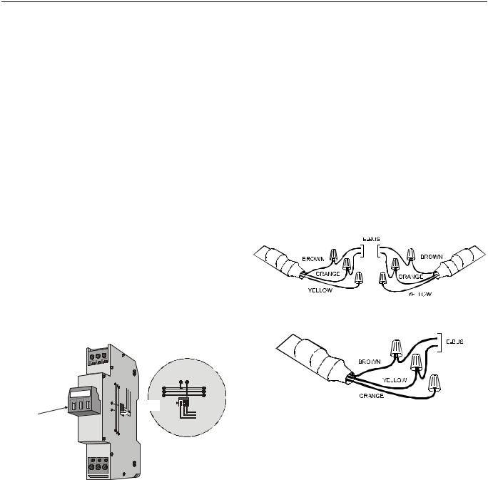
EXCEL 10 FAN COIL UNIT CONTROLLER SYSTEM ENGINEERING
Table 14. Output assignments of Excel 10 W7754 FCU Controller for various actuator types
output type |
stage |
|
OUT1 |
|
OUT2 |
||
19 |
|
20 |
21 |
|
22 |
||
|
|
|
|
||||
floating |
-- |
close |
|
open |
close |
|
open |
1-stage |
0 |
-- |
|
OFF |
-- |
|
OFF |
1 |
-- |
|
ON |
-- |
|
ON |
|
|
|
|
|||||
2-stage |
0 |
OFF |
|
OFF |
OFF |
|
OFF |
1 |
OFF |
|
ON |
OFF |
|
ON |
|
|
2 |
ON |
|
OFF |
ON |
|
OFF |
|
0 |
OFF |
|
OFF |
OFF |
|
OFF |
3-stage |
1 |
OFF |
|
ON |
OFF |
|
ON |
2 |
ON |
|
OFF |
ON |
|
OFF |
|
|
|
|
|||||
|
3 |
ON |
|
ON |
ON |
|
ON |
PWM |
-- |
-- |
|
PWM |
-- |
|
PWM |
thermal |
-- |
-- |
|
ON/OFF |
-- |
|
ON/OFF |
LONWORKS Termination
One or two LONWORKS terminations are required, depending on the given LonWorks bus layout.
Double termination is required only when the network is a daisy-chain configuration and the total wire length is greater than 1640 ft (500 m). The max. lengths described in Step 2 must be adhered to for either a daisy chain or free topology LONWORKS layout. See Fig. 19 for connection details for a doubly terminated bus. See Fig. 20 for connection details for a singly terminated bus.
Two different LONWORKS termination modules are available:
• LONWORKS termination module, order no.: |
209541B |
•LONWORKS connection / termination module (mountable
on DIN rails and in fuse boxes), order no.: |
XAL-Term |
NOTE: The Q7750A Zone Manager has an internal termination circuit, although jumpers are required at the terminal block to connect it. See form number 95-7509 for details.
Fig. 19. Termination Module connections for a doublyterminated FTT network
|
ll |
|
3 4 |
|
Honeywe |
|
|
|
m |
|
|
|
XAL-Ter |
1 |
5 |
|
4 |
||
3 |
shield |
shield |
|
|
0 |
6 |
|
|
plug-in |
LON |
|
|
Termination |
|
|
|
jumper |
FTT/LPT Bus |
removable screw-type |
|
|
|
|
|
Park Position |
|
|
|
|
FTT/LPT Free |
3-pole terminal block |
L |
L |
|
|
O |
O |
|
|
N |
N |
|
Fig. 20. Termination Module connections for a singlyterminated FTT network
Fig. 18. LONWORKS connection and termination module
25 |
EN0B-0377GE51 R0703 |

EXCEL 10 FAN COIL UNIT CONTROLLER SYSTEM ENGINEERING
Step 5. Order Equipment
After compiling a bill of materials through completion of the previous application steps, refer to Table 15 for ordering information. Contact Honeywell for information about controllers and Excel 10 wall modules with no logo.
Table 15. Excel 10 FCU Controller ordering information
Part Number |
Product Description |
Comments |
|
|
Excel 10 FCU Controllers |
|
|
W7752D2007 |
230 Vac, FTT LONWORKS version with |
|
|
reheat |
|
||
|
|
||
W7752E2004 |
230 Vac, FTT LONWORKS version without |
|
|
reheat |
|
||
|
|
||
W7752F2002 |
115 Vac, FTT LONWORKS version with |
|
|
reheat |
|
||
|
|
||
W7752G2000 |
115 Vac, FTT LONWORKS version without |
|
|
reheat |
|
||
|
|
||
W7752J2003 |
100 Vac, FTT LONWORKS version without |
|
|
reheat |
|
||
|
|
||
W7754K1001 |
230 Vac |
|
|
W7754L1009 |
24 Vac |
|
|
W7754M1007 |
230 Vac |
|
|
W7754N1004 |
230 Vac |
|
|
W7754P1000 |
230 Vac |
|
|
|
Excel 10 Wall Modules |
|
|
T7460 |
|
See Excel 10 wall module literature for details. |
|
T7560 |
|
||
|
|
||
|
Excel 10 Sensors |
|
|
C7068A1007 (Europe) |
Air Temperature Sensor |
Return air |
|
|
Echelon-Based Components and Parts |
|
|
Q7751A2002 (US) |
FTT LONWORKS router |
Order from local Echelon supplier (Europe) |
|
(UK) |
|||
(Europe) |
|
|
|
Q7752A2001 (US) |
FTT LONWORKS Serial Interface (SLTA) |
Order from local Echelon supplier (Europe) |
|
(UK) |
|||
(Europe) |
|
|
|
209541B |
FTT Termination Module |
Two required per LONWORKS segment. |
|
205979A (US only) |
SLTA Connector Cable for LONWORKS bus |
Serial interface to wall module or controller. |
|
|
Excel 10 Zone Manager |
|
|
Q7750A2003 |
FTT LONWORKS Zone Manager |
C-Bus to LONWORKS interface |
|
XD 505A |
9600 baud C-Bus Communications |
— |
|
Submodule |
|||
|
|
||
XD 508 |
(1 Megabit baud rate) C-Bus |
— |
|
Communications Submodule |
|||
|
|
||
|
Cabling |
|
|
— |
Serial Interface Cable, male DB-9 to female |
Obtain locally from any computer hardware |
|
DB-9 or female DB-25. |
vendor. |
||
|
|||
Honeywell (US) |
|
|
|
AK3791 (one twisted pair) |
LONWORKS (plenum): 22 AWG twisted pair |
Level IV 140°F (60°C) rating |
|
AK3792 (two twisted pairs) |
|||
solid conductor, non-shielded. |
|||
Belden (Europe) |
|
|
|
9H2201504 |
|
|
|
Honeywell (US) |
|
|
|
AK3781 (one twisted pair) |
LONWORKS (non-plenum): 22 AWG twisted |
Level IV 140°F (60°C) rating |
|
AK3782 (two twisted pairs) |
|||
pair solid conductor, non-shielded. |
|||
Belden (Europe) |
|
|
|
9D220150 |
|
|
|
Honeywell (US) AK3725 |
Inputs: 18 AWG (1.0 mm2) five wire cable |
Standard thermostat wire |
|
bundle. |
|||
|
|
||
Honeywell (US) AK3752 |
Outputs/Power: 14 to 18 AWG (2.5 to |
NEC Class 2 140°F (60°C) rating |
|
(typical or equivalent) |
1.0 mm2). |
||
|
|||
Honeywell (US) AK3702 |
18 AWG (1.0 mm2) twisted pair. |
Non-plenum |
|
(typical or equivalent) |
|||
|
|
||
Honeywell (US) AK3712 |
16 AWG (1.5 mm2) twisted pair. |
Non-plenum |
|
(typical or equivalent) |
|||
|
|
EN0B-0377GE51 R0703 |
26 |
 Loading...