


VR8300A Continuous Pilot Combination
Gas Control
APPLICATION
These continuous pilot gas controls are used in gas-fired appliances with capacities up to 200 cfh at 1 in. wc pressure drop (5.7 cmh at 0.25 kPa) on natural gas. Included are a manual valve, safety shutoff, two automatic operators, and a pressure regulator. See Table 2 for temperature range and regulator type.
The VR8300 setup for natural gas includes a 39369 LP Conversion Kit. The kit contains a new cap screw, a pressure regulator adjustment screw, a tapered spring and a conversion label. The control must be equipped with a standard servo pressure regulator. Step-opening gas controls cannot be converted.
INSTALLATION INSTRUCTIONS
Body Pattern:
Straight-through body pattern.
Inlet x Outlet Sizes Available:
1/2 x 1/2 in., 1/2 x 3/4 in., and 3/4 x 3/4 in. (factory-installed inlet flange).
Adapters:
Adapters available for 1/2 and 3/4 in. straight and angle connections. Refer to Table 3.
Electrical Ratings:
Voltage and Frequency: 24 Vac, 50/60 Hz.
Current Draw: 0.70A.
Capacity:
|
Capacity at 1 in. wc |
Minimum Regulated |
Maximum Regulated |
Size (Inlet x Outlet) |
Pressure Drop a |
Capacity |
Capacity |
1/2 in. x 1/2 in. |
180 cfh (5.1 cmh) |
30 cfh (0.8 cmh) |
225 cfh (6.4 cmh) |
|
|
|
|
1/2 in. x 3/4 in. |
190 cfh (5.4 cmh) |
30 cfh 0.8 cmh) |
290 cfh (8.2 cmh) |
|
|
|
|
3/4 in. x 3/4 in. |
200 cfh (5.7 cmh) |
30 cfh (0.8 cmh) |
300 cfh (8.5 cmh) |
|
|
|
|
aCapacity based on 1000 Btu/cu ft, 0.64 specific gravity natural gas at 1 in. wc pressure drop (37.3 MJ/cu m, 0.64 specific gravity natural gas at 0.25 kPa pressure drop).
Use conversion factors in Table 1 to convert capacities for other gases.
Table 1. Gas Capacity Conversion Factors.
|
Specific |
Multiply Listed |
Gas |
Gravity |
Capacity By |
|
|
|
Manufactured |
0.60 |
0.516 |
|
|
|
Mixed |
0.70 |
0.765 |
|
|
|
Propane |
1.53 |
1.62 |
|
|
|
Table 2. Temperature Range and Regulator Type.
|
Ambient |
|
|
Model |
Temperature Range |
Regulator |
|
Number |
° |
° |
Type |
|
F |
C |
|
VR8300A |
0° to 175° |
18° to 79° |
Standard-opening |
|
|
|
|
Table 3. Flange Part Numbers.
|
|
Part Number |
|
|
|
|
|
Inlet/Outlet |
Flange |
Without Hex |
With Hex |
Pipe Size |
Type |
Wrench |
Wrench |
|
|
|
|
1/2 in. NPT |
Straight |
393690-6 |
393690-16 |
|
|
|
|
|
Elbow |
393690-3 |
393690-13 |
|
|
|
|
3/4 in. NPT |
Straight |
393690-4 |
393690-14 |
|
|
|
|
|
Elbow |
393690-5 |
393690-15 |
|
|
|
|
NOTE: Flange kits include one flange with attached O-ring and fan mounting screw.
Approvals:
International Approval Services Listed: L2025007. Australian Gas Association Certificate: Applied for. Delta C: Pending approval.
®U.S. Registered |
Trademark |
|
|
|
|
|
|
|
|
|
|
|
|
|
|
|
|
|
|
|
|
|
|
|
|
|
|
|
|
|
|
|
|
|
|
|
|
|
|
|
|
|
|
|
|
|
69-0668-1 |
||||||||||||||||||||||||||||||||||||||||||||
Copyright © 1998 |
Honeywell Inc. • All Rights Reserved |
X-XX UL |
|||||||||||||||||||||||||||||||||||||||||||

VR8300A CONTINUOUS PILOT COMBINATION GAS CONTROL
INSTALLATION
When Installing this Product…
1.Read these instructions carefully. Failure to follow them could damage the product or cause a hazardous condition.
2.Check the ratings given in the instructions and on the product to make sure the product is suitable for your application.
3.Installer must be a trained, experienced service technician.
4.After installation is complete, check out product operation as provided in these instructions.
 WARNING
Fire or Explosion Hazard.
Can cause property damage, severe injury, or death.
Follow these warnings exactly:
1.Disconnect power supply before installing or servicing.
2.To avoid dangerous accumulation of fuel gas, turn off gas supply at the appliance service valve before starting installation, and perform Gas Leak Test after completion of installation.
3.Do not bend pilot tubing at gas control or pilot burner after compression fitting has been tightened, or gas leakage at the connection may result.
4.Always install sediment trap in gas supply line to prevent contamination of gas control.
5.Do not force gas control knob. Force or attempted repair may result in fire or explosion. Use only your hand to push down the reset button or turn the gas control knob. Never use any tools. If the gas control knob or reset button does not operate by hand, the gas control should be replaced by a qualified service technician.
 CAUTION
Equipment Hazard.
Improper installation can burn out thermostat heat anticipator.
Do not apply a jumper across or short the valve coil terminals.
IMPORTANT
These gas controls are shipped with protective seals over inlet and outlet tappings. Do not remove seals until ready to connect piping.
Follow the appliance manufacturer instructions if available; otherwise, use the instructions provided below.
Converting Between Natural and LP Gas
 WARNING
Fire or Explosion Hazard.
Can cause property damage, severe injury, or death.
1.Do not use a gas control set for natural gas on LP gas or a gas control set for LP gas on natural gas.
2.When making the conversion, the main and pilot burner orifices MUST be changed to meet the specifications of the appliance manufacturer.
Standard or slow-opening gas controls can be converted from one gas to another. To convert from natural gas to LP, use the 393691 LP Conversion Kit that is included with the VR8300A Gas Control. To convert from LP to natural gas, use the 394588 Natural Gas Conversion Kit (order separately). Step-opening gas controls cannot be converted.
To convert the control from one gas to another:
1.Turn off the main gas supply to the appliance.
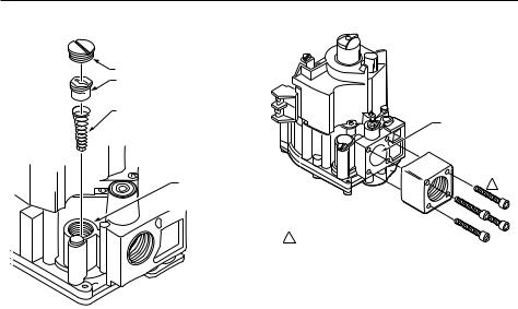
2.Remove the regulator cap screw and pressure regulator adjusting screw. See Fig. 5.
3.Remove the existing spring.
4.Insert the replacement spring with the tapered end down. See Fig. 1.
5.Install the new plastic pressure regulator adjustment screw so that the top of the screw is flush (level) with
the top of the regulator. Turn the pressure regulator adjustment screw clockwise  six complete turns. This provides a preliminary pressure setting of about 10.0 in. wc (2.5 kPA) for an LP regulator and a 3.5 in. wc (0.9 kPA) for a natural gas regulator.
6.Check the regulator setting with a manometer or by clocking the gas meter. See the Startup and Checkout section.
7.Install the new cap screw.
8.Mount the conversion label on the control.
9.Install the control and the appliance according to the appliance manufacturer instructions.
Install Adapters to Gas Control
If installing adapters on the gas control, mount them as follows:
Flanges:
1.Choose the appropriate flange for your application.
2.Remove the seal over the gas control inlet or outlet.
3.Ensure the O-ring is fitted into the groove of the flange. If the O-ring is not attached or is missing, do not use the flange.
4.With the O-ring facing the gas control, align the screw holes on the gas control with the holes in the flange. Insert and tighten the screws provided with the flange. See Fig. 2. Tighten the screws to 25 in. lb of torque to provide a gas-tight seal.
69-0668—1 |
2 |
VR8300A CONTINUOUS PILOT COMBINATION GAS CONTROL
|
COLOR CODE FOR |
||
|
LP |
NATRUAL |
|
|
GAS |
GAS |
|
CAP SCREW |
BLACK |
SILVER |
|
|
|
|
|
PRESSURE |
|
|
|
REGULATOR |
WHITE |
WHITE |
|
ADJUSTING |
|
|
|
SCREW |
|
|
|
TAPERED |
RED |
STAINLESS |
|
SPRING |
STEEL |
||
|
|||
PRESSURE
REGULATOR
HOUSING
M16015
Fig. 1. Install conversion kit in regulated gas control.
Bushings:
1. Remove the seal over the gas control inlet or outlet.
IMPORTANT
On LP installations, use a compound resistant to LP gas. Do not use Teflon tape.
2.Apply moderate amount of good quality pipe compound to bushing, leaving two end threads bare.
3.Insert bushing in gas control and thread pipe carefully into bushing until tight.
Follow the instructions below for piping, installing control, connecting pilot tubing, thermocouple and wiring. Make certain the leak test you perform on the control after completing the installation includes leak testing the adapters and screws. If you use a wrench on the valve after flanges are installed, use the wrench only on the flange, not the control.
Use Adapters to Solve Swing
Radius Problems
In some field service applications, it is difficult or impossible to thread the gas control onto the gas supply pipe because of space limitations. This problem can usually be resolved by using an adapter. The adapter is installed on the end of the supply pipe in place of the gas control, following the same precautions and instructions that are used for installing the gas control. After the adapter is installed, the gas control is attached to the adapter as outlined above. Note that using an adapter increases the overall length of the gas control.
GAS CONTROL
INLET
 FLANGE
1
9/64 IN. (3.6 MM)
HEX SCREWS (4)  1 DO NOT OVERTIGHTEN SCREWS.
TIGHTEN TO 25 IN. LB. |
M803 |
|
Fig. 2. Install flange to gas control.
Choose Gas Control Location
Do not locate the gas control where it can be affected by steam cleaning, high humidity, dripping water, corrosive chemicals, dust or grease accumulation, or excessive heat. To ensure proper operation, follow these guidelines:
•Locate gas control in a well ventilated area.
•Mount gas control high enough above the cabinet bottom to avoid exposure to flooding or splashing water.
•Make sure the ambient temperature does not exceed the ambient temperature ratings for each component.
•Cover gas control if appliance is cleaned with water, steam, or chemicals or to avoid dust and grease accumulation.
•Avoid locating gas control where exposure to corrosive chemical fumes or dripping water is likely.
Locate the gas control in the appliance vestibule on the gas manifold. In replacement applications, locate the gas control in the same location as the old gas control.
Install Piping to Gas Control
All piping must comply with local codes and ordinances or with the National Fuel Gas Code (ANSI Z223.1 NFPA No. 54), whichever applies. Tubing installation must comply with approved standards and practices.
1.Use new, properly reamed pipe free from chips. If tubing is used, make sure the ends are square, deburred and clean. All tubing bends must be smooth and without deformation.
2.Run pipe or tubing to the gas control. If tubing is used, obtain a tube-to-pipe coupling to connect the tubing to the gas control.
3.Install sediment trap in the supply line to the gas control. See Fig. 3.
3 |
69-0668—1 |

VR8300A CONTINUOUS PILOT COMBINATION GAS CONTROL
Install Gas Control
To install:
1.Mount the gas control 0 to 90 degrees, in any direction, from the upright position of the gas control knob, including vertically.
2.Mount the gas control so the gas flow is in the direction of the arrow on the bottom of the gas control.
3.Thread pipe the amount shown in Table 4 for insertion into the gas control. Do not thread pipe too far. Valve distortion or malfunction can result if the pipe is inserted too deeply into the gas control. See Fig. 3.
DROP |
|
|
|
HORIZONTAL |
PIPED |
GAS |
|
GAS |
CONTROL |
||
|
|||
|
SUPPLY |
|
|
|
RISER |
|
GAS |
|
|
CONTROL |
PIPED |
3 IN. |
|
GAS |
|
SUPPLY |
|
(76 MM) |
|
|
MINIMUM |
|
|
2 |
|
|
DROP |
|
|
HORIZONTAL |
|
3 IN. |
|
TUBING |
(76 MM) |
1 |
GAS |
MINIMUM |
SUPPLY |
|
|
|
2 |
|
|
|
GAS CONTROL
RISER  3 IN.
3 IN.
(76 MM)
MINIMUM
2
1ALL BENDS IN METALLIC TUBING SHOULD BE SMOOTH.
2CAUTION: SHUT OFF THE MAIN GAS SUPPLY BEFORE REMOVING END CAP TO PREVENT GAS FROM FILLING THE WORK AREA. TEST
FOR GAS LEAKAGE WHEN INSTALLATION IS COMPLETE. |
M3077 |
|
|
Fig. 3. Sediment trap installation. |
|
TWO IMPERFECT |
|
|
THREADS |
GAS CONTROL |
|
PIPE |
THREAD PIPE THE AMOUNT |
APPLY A MODERATE AMOUNT OF |
SHOWN IN TABLE FOR |
PIPE COMPOUND TO PIPE ONLY |
INSERTION INTO GAS CONTROL |
(LEAVE TWO END THREADS BARE). |
|
M3075B |
Fig. 4. Use moderate amount of pipe compound.
Table 4. NPT Pipe Thread Length in in.
Pipe |
Thread Pipe |
Maximum Depth Pipe can |
Size |
this Amount |
be Inserted into Control |
|
|
|
3/8 in. |
9/16 in. |
3/8 in. |
|
|
|
1/2 in. |
3/4 in. |
1/2 in. |
|
|
|
3/4 in. |
13/16 in. |
3/4 in. |
|
|
|
IMPORTANT
On LP installations, use compound resistant to LP gas. Do not use Teflon tape.
4.Apply a moderate amount of good quality pipe compound (DO NOT use Teflon tape) to pipe only, leaving two end threads bare. On LP installations, use compound resistant to LP gas.
5.Remove seals over the gas control inlet and outlet if necessary.
6.Connect the pipe to the gas control inlet and outlet. Use a wrench on the square ends of the gas control. If an adapter is used, place the wrench on the adapter rather than the gas control. Refer to Fig. 5 and 6.
PRESSURE REGULATOR |
CONVENIENCE |
|
ADJUSTMENT |
TERMINALS (2) |
|
(UNDER CAP SCREW) |
(OPTIONAL) |
|
OUTLET |
|
|
PRESSURE |
|
|
TAP |
|
|
INLET |
|
|
THERMOCOUPLE |
GAS |
|
CONNECTION |
||
CONTROL |
||
|
||
RED RESET BUTTON |
KNOB |
WIRING
TERMINALS (2)
OUTLET
PRESSURE
TAP
 OUTLET
PILOT OUTLET
PILOT ADJUSTMENT (UNDER CAP SCREW)
M16013
Fig. 5. Top view of gas control.
APPLY WRENCH
TO FLANGE ONLY
M16012
Fig. 6. Proper use of wrench on gas control.
Connect Pilot Gas Tubing
1.Cut tubing to desired length and bend as necessary for routing to pilot burner. Do not make sharp bends or deform the tubing. Do not bend tubing at gas control or pilot burner after compression fitting is tightened, because this can result in gas leakage at the connection.
69-0668—1 |
4 |
 Loading...