


XL 1000 Series
FOR SMOKE CONTROL
HONEYWELL EXCEL 5000 OPEN SYSTEM
CONTENTS |
|
General ............................................................................... |
3 |
Before Installation ............................................................. |
3 |
Installation ......................................................................... |
3 |
Wiring ................................................................................. |
4 |
XL1000 Series Power Consumption .............................. |
5 |
I/O Modules ................................................................... |
5 |
Description of the XL1000 Controller............................... |
7 |
Overview........................................................................ |
7 |
Terminal Blocks ............................................................. |
8 |
LonWorks Interface........................................................ |
8 |
Ethernet Interface .......................................................... |
8 |
RS232C Serial Interface Ports....................................... |
9 |
Port 1 (Factory Service Interface) ............................ |
9 |
Port 2 (Browser Interface) ........................................ |
9 |
Port 3 (Modem Interface) ......................................... |
9 |
CF Port LED, Request Button, and Slot......................... |
9 |
USB Interface Downloads.............................................. |
9 |
LEDs and Buttons.......................................................... |
9 |
LonWorks Service LED and Service Button............. |
9 |
Power Supply LED......................................................... |
9 |
Binary Input (terminals 3+4) LED................................... |
9 |
Binary Output (terminals 7+8) LED................................ |
9 |
Binary Output (terminals 9+10) LED............................ |
10 |
Ethernet LEDs ............................................................. |
10 |
Ethernet Link LED .................................................. |
10 |
Ethernet Activity LED ............................................. |
10 |
LEDs L1 and L2 ........................................................... |
10 |
Reset Button ................................................................ |
10 |
Mounting .......................................................................... |
10 |
Before Installation ........................................................ |
10 |
Dimensions .................................................................. |
10 |
DIN Rail Mounting/Dismounting ............................. |
11 |
Wall/Panel Mounting/Dismounting ......................... |
11 |
Swivel Cover Lock.................................................. |
11 |
Power Supply................................................................... |
12 |
Lightning Protection ..................................................... |
14 |
Interfaces and Bus Connections .................................. |
14 |
Technical Data............................................................. |
14 |
System Data........................................................... |
14 |
INSTALLATION AND COMMISSIONING INSTRUCTIONS
Operational Environment........................................ |
14 |
LonWorks Communications ........................................... |
14 |
General Information ..................................................... |
14 |
Connecting to the LONWORKS Network......................... |
14 |
Binary Input and Outputs................................................ |
15 |
Wiring........................................................................... |
15 |
Binary Input .................................................................. |
15 |
Binary Outputs ............................................................. |
15 |
Hardware Limits...................................................... |
15 |
Protocolling .................................................................. |
15 |
XL1000 Configuration...................................................... |
15 |
Smoke Control Configuration ....................................... |
16 |
Data File Set-Up........................................................... |
16 |
Panel Reset.................................................................. |
16 |
Typical Power Limited Circuit for XL1000 .................... |
17 |
Connecting Single Bus Controller Systems.................. |
17 |
XL1000, I/O Modules on Single Rail....................... |
17 |
XL1000, I/O Modules on Rails in Single Cabinet .... |
17 |
I/O Modules in Separate Rooms............................. |
18 |
LONWORKS Bus Topologies .......................................... |
18 |
Mounting/Dismounting Modules .................................... |
18 |
Mounting/Dismounting Sockets.................................... |
18 |
Mounting Sockets ................................................... |
18 |
Connecting Sockets................................................ |
19 |
Dismounting Terminal Sockets ............................... |
19 |
Mounting/Dismounting Electronic Modules .................. |
20 |
Mounting Electronic Modules.................................. |
20 |
Dismounting Electronic Modules ............................ |
20 |
Connecting HMIs or Laptops........................................ |
20 |
Connecting Laptops (XW-Online/CARE) ................ |
20 |
Description of the I/O Modules ....................................... |
21 |
Common Features ....................................................... |
21 |
Analog Input Modules .................................................. |
22 |
Types of Analog Input Modules .............................. |
22 |
Features ................................................................. |
22 |
Terminals................................................................ |
22 |
XFL821AU Connection Examples .......................... |
23 |
Analog Output Modules................................................ |
24 |
Types of Analog Output Modules ........................... |
24 |
Features ................................................................. |
24 |
Terminals................................................................ |
24 |
Technical Data........................................................ |
24 |
Copyright © 2008 Honeywell GmbH All Rights Reserved |
|
EN1B-0409GE51 R0908A |

General |
XL1000 |
Modules with Manual Overrides.............................. |
25 |
XFL822AU Connection Example ............................ |
25 |
Synchronization Behavior of Analog Output Module |
|
Configured as Floating Output ................................ |
25 |
Binary Input Modules.................................................... |
26 |
Types of Binary Input Modules................................ |
26 |
Features.................................................................. |
26 |
Terminals ................................................................ |
26 |
Technical Data ........................................................ |
26 |
Status LEDs............................................................ |
26 |
XFL823AU Connection Examples........................... |
27 |
Relay Output Modules .................................................. |
28 |
Types of Relay Output Modules.............................. |
28 |
Features.................................................................. |
28 |
Terminals ................................................................ |
28 |
Permissible Loads................................................... |
29 |
Status LEDs with Manual Overrides ....................... |
29 |
Connection Example............................................... |
30 |
Troubleshooting............................................................... |
31 |
Testing Wiring Connections.......................................... |
31 |
I/O Modules Troubleshooting........................................ |
31 |
Power LED of I/O Modules ..................................... |
32 |
Service LED of I/O Modules.................................... |
32 |
Trademark Information
Echelon, LON, LONMARK, LONTALK, LONWORKS, Neuron, are trademarks of Echelon Corporation registered in the United States and other countries.
EN1B-0409GE51 R0908A |
2 |
XL1000
 WARNING
This equipment generates, uses, and can radiate radio frequency energy, and if not installed and used in accordance with the instructions manual, may cause interference to radio communications. It has been tested and found to comply with the limits for a Class A computing device pursuant to Subpart J of Part 15 of FCC Rules, which are designed to provide reasonable protection against such interference when operated in a commercial environment. Operation of this equipment in a residential area is likely to cause interference, in which case the user, at his own expense, will be required to take whatever measures may be required to correct the interference. Any unauthorized modification of this equipment may result in the revocation of the owner’s authority to continue its operation.
General
The XL1000 Series is designed to provide heating, ventilating and air-conditioning control. They can operate either standalone, or networked to Honeywell central workstations such as EBI. These controllers can also be used for smoke control system monitoring and control, for monitor and control of fire (UL864), and general purpose signaling (UL2017). In UL2017 applications, the product can be used as a type NM (Non-Monitored) system. It is also approved for UL916 (Energy Management Equipment.)
The XL1000 Series can be used for smoke control applications when used in conjunction with a UL-listed fire alarm control panel (FACP) and UL-listed fire fighters’ smoke control station (FSCS).
Before Installation
1.Unpack door and remove the XL1000 from carton. Check equipment and report any damage to a Honeywell representative.
2.Verify cabinet is installed correctly.
3.Securely mount the XL1000 to a rigid structural surface using at least four sets of 1/4 in. (6 mm) mounting hardware (supplied locally).
NOTE: Anchoring materials must be suitable for the mounting surface (wood, concrete, steel). Mounting must comply with all local codes.
4.Obtain correct number and type of sheet metal screws for subpanel. Installation of a full-size subpanel requires six no. 10 x ½-inch (13 mm) sheet metal screws (not supplied). Installation of a smaller subpanel requires four no. 10 x ½-inch (13 mm) sheet metal screws (not supplied).
5.Obtain 14505159-001 Tamper Switch per job requirements. Installation of Tamper Switch is optional.
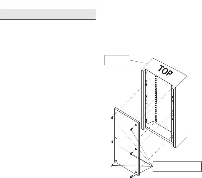
Installation
Mount controller subpanel in cabinet so all labeling is visible. Secure full-size subpanel in place with six no. 10 x ½-inch (13 mm) sheet metal screws (not supplied). Secure smaller subpanel with four no. 10 x ½-inch (13 mm) sheet metal screws (not supplied).
NOTE: Subpanel must mount flat and should not bulge or recess anywhere.
FULL-SIZE
CABINET
SIX NO. 10 x ½-INCH (13 mm)
SHEET METAL SCREWS
Fig. 1. Mounting controller subpanel in cabinet (full-size subpanel cabinet shown)
3 |
EN1B-0409GE51 R0908A |
Wiring |
XL1000 |
Wiring
All wiring to the XL1000 controller is unsupervised, except as noted.
All circuits are power limited, except for AC power circuits, relay contacts and other circuits as noted.
All field wiring terminals accept 24 AWG to 14 AWG (0.25 mm2 to 2 mm2) conductors except as noted.
All wiring must conform to local codes, ordinances, and regulations. Refer to job drawings for details.
Verify that the voltage difference between any conductor and earth ground does NOT exceed 150 Vac.
1.Connect input/output device wiring, LONWORKS Bus transmission wiring, and 14507063 Power Cable to Controller per job drawings. Fig. 2 and Fig. 3 show typical controller wiring. Four Power Module models are available (see Table 2).
2.Connect line voltage to Terminals H and N of the 14507287 Power Module. Connect a good earth ground to Terminal G of the Power Module. Fig. 13 through Fig. 15 show typical power wiring.
3.For Power Modules -001 through -007, leave power to Power Supply and Controller OFF. Connect 14507063 Power Cable from Controller to Power Module.
 WARNING
Risk of electric shock or equipment damage!
►Subpanel and Controller power must remain OFF until Controller is checked.
4.Install optional Tamper Switch on cabinet per instructions in the cabinet installation instructions. Wire Tamper Switch per job drawings.
5.Mount cabinet door.
CAUTION
Risk of electric equipment damage! Excessive static can burn out equipment.
►Observe proper anti-static material handling practices when installing or servicing PC parts and related components.
►Observe proper equipment and body grounding practices.
►Discharge static electricity from your body before handling parts.
|
|
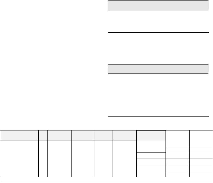
Table 1. Connector terminal specifications |
||||
connector terminal |
pin |
signal type |
input / |
voltage |
max. |
max. current |
|
|
|
output |
type |
voltage |
|
analog input |
AI |
input |
SIGNAL |
±12 V |
±20 mA |
digital input |
DI |
input |
SIGNAL |
±10 V |
±20 mA |
|
|
|
|
|
|
analog output |
AO |
output(1 |
SIGNAL |
±10 V |
±20 mA |
digital output |
DO |
output(2 |
AC/DC |
±24 VAC/DC |
±50 mA |
totalizer output |
TI |
input |
SIGNAL |
±12 V |
±12 mA |
signal ground |
GND |
-- |
-- |
-- |
-- |
(1 special application; (2 regulated
max. |
max. line |
frequency |
impedance |
9600 baud |
8K ohms |
--15K ohms
9600 baud 8K ohms
--10K ohms
100 Hz
----
Table 2. Power module models
|
model |
|
transformer max. input |
|
(48 VA) controller |
|
accessory output |
|
convenience outlet |
|||||
|
|
Vac |
|
current draw |
|
Hz |
|
VAC output |
|
|
||||
|
|
|
|
|
|
|
|
|
|
|
||||
14507287-001 |
120 |
|
0.5 A |
60 |
24 |
|
|
|
|
120 Vac, 10A |
||||
|
|
|
|
|
|
|
|
|
|
|
||||
14507287-002 |
120 |
|
1.7 A |
60 |
24 |
24 |
Vac, 100 VA, 24 |
Vac, 40 VA |
|
120 Vac, 10A |
||||
|
|
|
|
|
|
|
|
|
|
|
||||
14507287-003 |
120 |
|
1.7 A |
60 |
24 |
24 |
Vac, 100 VA, 24 |
Vdc, 600 mA |
|
120 Vac, 10A |
||||
14507287-007 |
120 |
|
120 A |
60 |
24 |
-- |
|
|
-- |
|||||
EN1B-0409GE51 R0908A |
4 |
XL1000 |
|
Wiring |
XL1000 Series Power Consumption |
|
I/O Modules |
When selecting the appropriate power supply, the power consumption of the I/O modules must be taken into account.
Table 3. XL1000 power consumption
|
max. power consumption |
|
model |
24 Vac, 60 Hz |
24 Vdc |
XL1000 with watchdog |
500 mA |
500 mA |
load |
|
|
XL1000 without watchdog |
500 mA |
500 mA |
load |
|
|
XFL821AU |
130 mA |
80 mA |
|
|
|
XFL822AU, XFLR822AU |
160 mA |
90 mA |
|
|
|
XFL823AU |
180 mA |
130 mA |
XFL824AU, XFLR824AU |
140 mA |
90 mA |
I/O Modules
The XL1000 operates together with LONWORKS I/O modules (dark-gray housings) with communication via LONWORKS (FTT10-A, link power compatible) for easy integration and use with 3rd-party controllers.
Terminal Sockets
The I/O modules are mounted on the appropriate terminal sockets.
Color Coding
To distinguish modules and components, the following color coding is used:
Table 4. Color coding of I/O Modules
|
color |
|
part |
|
|
||
|
red |
|
All of the user-accessible adjustable |
|
|
|
mechanical parts (i.e., bridge connectors and |
|
|
|
locking mechanism) and operating controls |
|
|
|
(manual overrides, etc.) |
|
|
|
|
|
dark-gray |
|
LONWORKS I/O modules |
|
|
|
|
5 |
EN1B-0409GE51 R0908A |
|
Wiring |
|
|
|
|
|
|
|
|
|
|
|
|
|
|
|
|
|
|
|
XL1000 |
|
|
|
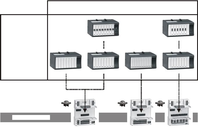
I/O Module Overview |
|
|
|
|
|
|
|
|
|
|
|
|
|
|
|
|
|
|
|
|||
|
|
|
Table 5. Overview of I/O modules and corresponding terminal sockets |
|
|
|
|
||||||||||||||||
|
|
|
|
|
|
|
|
|
|
|
|
|
|
|
|
|
|
|
|
|
|
|
|
|
LONWORKS I/O |
|
description |
|
inputs |
|
outputs |
|
manual |
|
status |
|
socket |
scope of delivery |
|
||||||||
|
module |
|
|
|
|
overrides |
|
LEDs 1) |
|
|
|||||||||||||
|
|
|
|
|
|
|
|
|
|
|
|
|
|
|
|
|
|||||||
|
XFL821AU |
|
Analog Input Module |
8 |
|
|
|
– |
|
– |
|
|
– |
|
|
|
1 terminal socket, |
|
|||||
|
|
|
|
|
|
|
|
|
|
|
|
|
|
|
|
|
|
|
|
|
|||
|
XFL822AU |
|
Analog Output Module |
|
– |
8 |
|
– |
8 |
|
|
XS821-22 |
1 bridge connector |
|
|||||||||
|
|
|
|
|
|
|
|
|
|
|
|
|
|
|
|
|
|
|
|
1 swivel label holder |
|
||
|
XFLR822AU |
|
Analog Output Module |
|
– |
8 |
8 |
8 |
|
|
|
|
|
||||||||||
|
|
|
|
|
|
|
|
|
|
|
|||||||||||||
|
|
|
|
|
|
|
|
|
|
|
|
|
|
|
|
|
|
|
|
1 terminal socket, |
|
||
|
XFL823AU |
|
Binary Input Module |
12 |
|
|
|
– |
|
– |
12 |
|
XS823 |
1 bridge connector |
|
||||||||
|
|
|
|
|
|
|
|
|
|
|
|
|
|
|
|
|
|
|
|
1 swivel label holder |
|
||
|
XFL824AU |
|
Relay Output Module |
|
– |
6 2) |
|
– |
6 |
|
|
|
|
1 terminal socket, |
|
||||||||
|
|
|
|
|
|
|
|
|
|
|
|
|
|
|
|
|
|
XS824-25 |
1 bridge connector |
|
|||
|
XFLR824AU |
|
Relay Output Module |
|
– |
6 2) |
6 |
6 |
|
|
1 swivel label holder |
|
|||||||||||
|
|
|
|
|
|
|
|
||||||||||||||||
|
|
|
|
|
|
|
1 long cross connector |
|
|||||||||||||||
|
|
|
|
|
|
|
|
|
|
|
|
|
|
|
|
|
|
|
|
|
|
||
|
1) In addition to |
the power LED and service LED |
|
|
|
|
|
|
|
|
|
|
|
|
|
|
|
|
|||||
|
2) Changeover outputs |
|
|
|
|
|
|
|
|
|
|
|
|
|
|
|
|
|
|
|
|||
|
|
|
|
|
|
|
|
|
|
|
|
|
|
|
|
|
|
|
|
|
|
|
|
|
|
|
|
|
|
|
|
|
|
|
|
|
|
|
|
|
|
|
|
|
|
|
|
|
|
|
|
|
|
|
|
|
|
|
|
|
|
|
|
|
|
|
|
|
|
|
|
|
|
|
|
|
|
|
|
|
|
|
|
|
|
|
|
|
|
|
|
|
|
|
|
|
|
|
|
|
|
|
|
|
|
|
|
|
|
|
|
|
|
|
|
|
|
|
|
|
|
|
|
|
|
|
|
|
|
|
|
|
|
|
|
|
|
|
|
|
|
|
|
LonWorks Bus
XS821-22 |
|
XS823 |
|
XS824-25 |
Fig. 2. Overview of I/O modules and terminal sockets
EN1B-0409GE51 R0908A |
6 |

XL1000 |
Description of the XL1000 Controller |
Description of the XL1000 Controller
Overview
power supply LED (green) |
|
|
|
|
|
binary output (terminals 9+10) LED (yellow) |
||||||||
(LED ON = power supplied) |
|
|
|
|
|
(LED ON = application has closed contact) |
||||||||
|
|
|
|
|
|
|
||||||||
binary input (terminals 3+4) LED (yellow) |
|
|
|
|
|
binary output (terminals 7+8) LED (red) |
||||||||
(LED ON = input closed) |
|
|
|
|
|
(LED ON = watchdog has closed contact) |
||||||||
|
|
|
|
|
|
|
|
|
|
|
|
|
|
|
Ethernet link LED (yellow) |
|
|
|
|
|
|
LED2 (currently unused) |
|||||||
(LED ON = Ethernet link is enabled) |
|
|
|
|
|
|
||||||||
|
|
|
|
|
|
|
|
|
|
|||||
|
|
|
|
|
|
|
|
|
|
|
||||
Ethernet activity LED (yellow) |
|
|
|
|
|
|
LED1 (currently unused) |
|||||||
(LED ON = Ethernet active) |
|
|
|
|
|
|
||||||||
|
|
|
|
|
|
|
|
|
|
|||||
|
|
|
|
|
|
|
|
|
|
|
|
|
|
|
|
|
|
|
|
|
|
|
|
|
|
|
|
|
|
|
|
|
|
|
|
|
|
|
|
|
|
|
|
|
|
|
|
|
|
|
|
|
|
|
|
|
|
|
|
|
|
|
|
|
|
|
|
|
|
|
|
|
|
|
|
|
|
|
|
|
|
|
|
|
|
|
|
|
|
|
|
|
|
|
|
|
|
|
|
|
|
|
|
|
|
reset button |
|
ATTENTION: |
|
|
Never unscrew and |
|
|
dismount the inner |
|
|
metallized cover while |
|
|
the XL1000 is powered! |
NO CONNECTION |
|
Danger of short-circuiting! |
||
|
LonWorks service LED (yellow) |
|
L1 |
NOT USED |
(for meaning of LED behavior, see Table 1) |
LON |
||
LonWorks service button |
L2 |
CF |
|
|
NOT USED |
||
(pushing broadcasts service pin message) |
|
LON |
1 |
2 |
3 |
7 8 9 10 1112 |
|
1 2 3 4 5 6 |
USB interface |
|
|
|
NO CONNECTION |
|
NO CONNECTION |
upper terminal block (removable) |
RS232C serial interface, port 1 |
(terminals 7 thru 12) |
(standard male 9-position sub-D) |
lower terminal block (removable) |
Ethernet interface (8-position, |
(terminals 1 thru 6) |
shielded RJ45 connector jack, CAT5) |
|
LonWorks interface (8-position, |
|
unshielded RJ45 connector jack) |
Fig. 3. Connections to the XL1000 Controller
7 |
EN1B-0409GE51 R0908A |
Description of the XL1000 Controller |
XL1000 |
Terminal Blocks
The XL1000 features two rows of removable terminal blocks (located at the front left-hand side; see Fig. 3) for the connection of cables to the two binary outputs and the binary input as well as for connecting LONWORKS and the power supply. A nearby sticker provides an overview of the terminal assignment (see Fig. 4).
|
! |
|
|
|
|
|
|
|
|
|
|
|
LON |
||
|
|
|
|
|
|
|
|
|
|
|
|
||||
|
|
|
|
|
|
|
|
|
|
|
|
|
|
||
|
|
8 |
|
9 |
|
10 |
|
11 |
|
||||||
7 |
|
|
|
|
12 |
||||||||||
|
|
|
|
|
|
|
|
|
|
|
|
|
|
||
24V |
|
|
|
|
|
|
|
|
|
|
|
LON |
|||
|
|
|
|
|
|
|
|
|
|
|
|||||
~ |
0 |
|
|
|
|
|
|
|
|
|
|
|
|||
|
|
|
|
|
|
|
|
|
|
|
|||||
1 |
|
2 |
|
3 |
|
4 |
|
|
5 |
6 |
|||||
Fig. 4. Terminal assignment sticker
Maximum torque for fastening the wiring terminal screws is 0.5 Nm (4.5 lb-in).
Table 6 provides a more-detailed explanation of the terminals and their functions.
Table 6. Overview of terminals and functions
term. |
function |
1+2 |
power supply (24 Vac) |
|
a binary input (normally-open, 36 Vdc; pin 4 is the |
|
signal ground), freely configurable (using CARE 7) |
3+4 |
to read input from either 1) a field device or 2) a |
|
collective alarm input or 3) a 2nd XL1000 whose |
|
duties it could then assume in the event of its failure |
5+6 |
LONWORKS |
|
|
|
a binary output / "watchdog relay" (SPDT, normally |
|
closed, 24 Vac, max. 2 A permanent load), per- |
7+8 |
manently configured to output to an alarm device |
|
(which can then signal that XL1000 is |
|
malfunctioning) |
|
a binary output (potential-free contact, SPST, |
|
normally-open, 24 Vac, max. 2 A permanent load), |
9+10 |
configurable (using CARE) to output to either 1) a |
field device or 2) a 2nd XL1000 which could then |
|
|
assume the 1st XL1000’s duties in the event of its |
|
failure |
11+12 |
LONWORKS |
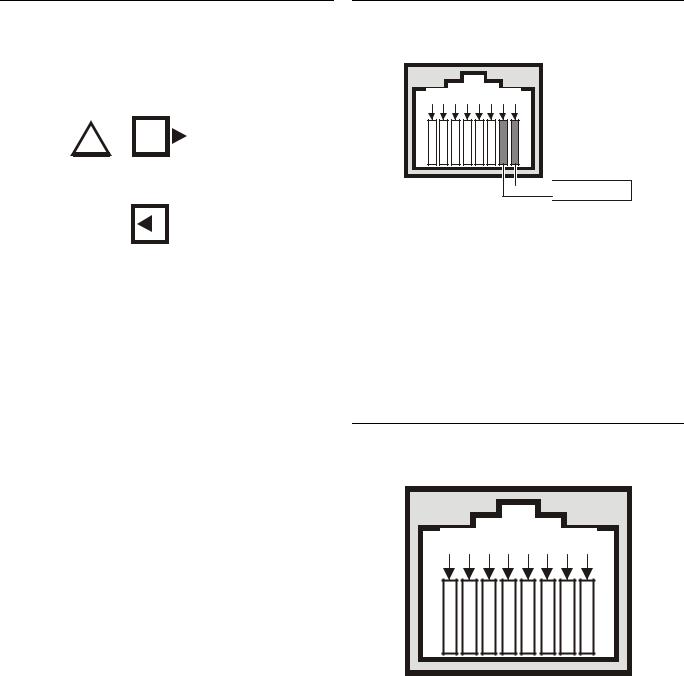
LonWorks Interface
The XL1000 is equipped with a LONWORKS interface (specifically: an RJ45 jack) for communication on LONWORKS networks.
8 7 6 5 4 3 2 1
 LonWorks
Fig. 5. LonWorks interface (RJ45 jack)
There are two methods of connecting the XL1000 to the LONWORKS network (both or either connection method can be used):
•via terminals 5+6 and 11+12 of the terminal blocks (see Fig. 3); and/or
•via the corresponding jack located to the right of the terminal blocks (see Fig. 5).
See also section "LonWorks Service LED and Service Button" on page 9 for details on the corresponding LONWORKS service LED and one LONWORKS service button.
Ethernet Interface
The XL1000 is equipped with a 10/100-Mbaud Ethernet interface (specifically: an RJ45 jack) permitting communication (as per IEEEC 802.3) on BACnet/IP networks.
8 7 6 5 4 3 2 1
Fig. 6. Ethernet interface
When thus connected, the user sitting at a platform hosting EBI can thus e.g. view and edit the time programs, trend values, etc. of the other devices in the BACnet/IP network.
This Ethernet jack conforms to the specifications of the following two Ethernet sub-standards:
•100Base-TX (twisted pair / star wiring; 100 Mbaud Ethernet based on Manchester signal encoding over category 5 or better twisted pair cable; max. segment length = 100 meters) and
EN1B-0409GE51 R0908A |
8 |
XL1000 |
Description of the XL1000 Controller |
•10Base-T (twisted pair / star wiring; 10 Mbaud Ethernet based on Manchester signal encoding over category 3 or better twisted pair cable; max. segment length =
100 meters).
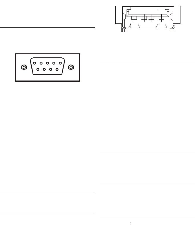
RS232C Serial Interface Ports
The XL1000 is equipped with three male 9-pin sub-D jacks into which corresponding female 9-pin sub-D plugs can be inserted for various different purposes (see following subsections). These ports allow data transmission rates of 9.6, 19.2, 76.8, or 115.2 kBaud (the default).
 12.5 mm

Fig. 8. USB interface
Alternatively, either of the following two adapters can also be used: SMC 2208USB/ETH and SMC 2209USB/ETH.
Fig. 7. RS232C serial interface
The user can configure the specific desired data transmission rate of each individual RS232C port; it is thus possible for the three ports to operate simultaneously at three different rates.
Port 1 (Factory Service Interface)
Port 1 is intended for the connection (as needed) of a platform for the purpose of servicing (in the factory, only) the XL1000. In this context, "servicing" comprises a group of different activities including:
•updating portions of the XL1000’s Operating System (namely: LINUX, BACstack, Apache Web-Server) and
•diagnostics (Linux, firmware).
Port 2 (Browser Interface)
NO CONNECTION.
Port 3 (Modem Interface)
NO CONNECTION.
CF Port LED, Request Button, and Slot
NO CONNECTION.
USB Interface Downloads
The XL1000 is equipped with a USB port into which a standard USB type-A connector can be inserted. This USB interface is the recommended interface for downloading applications. The following USB host networking adapter has been approved: BELKIN DIRECT CONNECT (BELKIN order no.: F5U104 or F5U104G at www.belkin.com).
LEDs and Buttons
LonWorks Service LED and Service Button
The XL1000 is equipped with a LONWORKS service LED and a LONWORKS service button, together marked "LON" (see Fig. 3). They are used for commissioning the XL1000 and for troubleshooting.
LonWorks Service Button
When the LONWORKS service button is pressed, the service pin message is broadcast on the LONWORKS network, and all LONWORKS tools currently connected to the LONWORKS network will receive this message.
LonWorks Service LED
The LONWORKS service LED can display various behaviors having different meanings (see Table 7).
Power Supply LED
The LED marked "  " indicates whether or not the XL1000 is currently under power. Specifically, when it is lit, the XL1000 is under power; when it is dark, the XL1000 is not under power.
Binary Input (terminals 3+4) LED
The LED marked "  " indicates the state of the binary input (which is a normally-open contact) located at terminals 3 and 4. Specifically, when it is lit, the binary input is closed; when it is dark, the binary input is open.
Binary Output (terminals 7+8) LED
The LED marked " " indicates the state of the binary output ("watchdog" relay) at terminals 7 and 8 (which is a normally closed contact). Specifically, when it is lit, the alarm contact is open; when it is dark, the alarm contact is closed.
9 |
EN1B-0409GE51 R0908A |

Mounting |
XL1000 |
Binary Output (terminals 9+10) LED
The LED marked "  " indicates the state of the binary output at terminals 9 and 10 (which is a normally-open contact). Specifically, when it is lit, this means that the application has closed the relay; when it is dark, the relay is open.
Table 7. LONWORKS service LED behaviors / meanings
|
|
LED behavior |
|
meaning |
|
|
LED remains OFF after |
|
Defective XL1000 hardware |
1 |
|
|
(e.g. power supply problems, |
|
|
power-up. |
|
clock problems, or defective |
|
|
|
|
||
|
|
|
|
Neuron Chip). |
|
|
|
|
|
2 |
|
LED is lit continuously after |
|
Defective XL1000 hardware. |
|
first power-up. |
|
||
|
|
|
|
|
|
|
LED flashes at power-up, |
|
Neuron chip lacks LONWORKS |
|
|
|
interface program. Remedy: |
|
3 |
|
goes OFF, and then is lit con- |
|
|
|
|
Use Excelon or LonMaker, set |
||
|
|
tinuously. |
|
|
|
|
|
XL1000 online. |
|
|
|
|
|
|
|
|
|
|
|
|
|
|
|
XL1000 probably experiencing |
4 |
|
LED flashes briefly |
|
continuous watchdog resets, |
|
periodically. |
|
or external memory or |
|
|
|
|
||
|
|
|
|
EEPROM is corrupt. |
|
|
|
|
|
5 |
|
LED repeatedly blinks ON for |
|
XL1000 is unconfigured but |
|
|
has an application. Remedy: |
||
|
1 s and OFF for 1 s. |
|
||
|
|
|
Commission XL1000. |
|
|
|
|
|
|
|
|
|
|
|
|
|
OFF for approx. 10 s. After- |
|
|
|
|
wards, the service LED turns |
|
|
6a |
|
ON and remains ON, |
|
Return XL1000 to factory. |
|
|
indicating completion of the |
|
|
|
|
blanking process. |
|
|
|
|
OFF for approx. 1 s. After- |
|
|
6b |
|
wards, the service LED is lit |
|
Return XL1000 to factory. |
|
|
continuously. |
|
|
|
|
OFF for 1 ─ 15 s, depending |
|
XL1000 is unconfigured but |
|
|
on application size and system |
|
|
6c |
|
clock. Afterwards, service LED |
|
has an application. Remedy: |
|
|
repeatedly flashes ON for 1 s |
|
Commission XL1000. |
|
|
and OFF for 1 s. |
|
|
7 |
|
LED remains OFF after a |
|
XL1000 is configured and |
|
short ON duration. |
|
running normally. |
|
|
|
|
||
|
|
|
|
XL1000 received a WINK |
8 |
|
LED flashes ON. |
|
command from LONWORKS; |
|
|
other physical outputs are |
||
|
|
|
|
|
|
|
|
|
unaffected. |
|
|
|
|
|
In case of a problem, check if the LONWORKS service LED's behavior is changed by resetting the XL1000 using the reset button. Please contact Honeywell if this does not solve the problem.
Ethernet LEDs
The XL1000 is equipped with two Ethernet LEDs (see Fig. 3).
Ethernet Link LED
The LED marked " 


 " indicates the Ethernet link's status. Specifically, it is lit whenever an Ethernet jack has been inserted into the corresponding port and the software has established the Ethernet link. It is dark when the link has been disabled.
Ethernet Activity LED
The LED marked " ↔ " indicates whether or not the Ethernet link is currently active. Specifically, when it flashes, this means that signals are being transmitted / received on the Ethernet network; when it is dark, no messages are being transmitted/received.
LEDs L1 and L2
At present, these LED's are not in use.
Reset Button
The reset button can be pressed only using a long, thin tool (e.g. a screwdriver). Pressing it reboots the XL1000’s operating system and restarts the application.
Mounting
Before Installation
IMPORTANT
To allow the evaporation of any condensation resulting from low shipping / storage temperatures, keep the controller at room temperature for at least 24 h before applying power.
In order to meet the criteria for CE certification, the XL1000 must be mounted inside an electrical panel.
Dimensions
The XL1000 has the following dimensions (W x L x H):
278 x 190 x 61 mm. Its housing conforms to IP20. Its pollution degree (2) makes it suitable for use in residential controls, commercial controls, in a clean environment, or non-safety controls for installation on or in appliances.
The XL1000 is suitable for mounting on a standard rail (DIN EN 50022-35 x 7,5) for installation in appropriately-sized wiring cabinets. Allow sufficient clearance (approx. 30 mm) to access the interfaces and to open the swivel cover (see Fig. 9).
EN1B-0409GE51 R0908A |
10 |
 Loading...