


XI581 / XI582
BUSWIDE OPERATOR INTERFACE
USER GUIDE
Software License Advisory This document supports software that is proprietary to Honeywell Inc. and/or to third-party software vendors. Before software delivery, the end user must execute a software license agreement that governs software use. Software license agreement provisions include limiting use of the software to equipment furnished, limiting copying, preserving confidentiality, and prohibiting transfer to a third party. Disclosure, use, or reproduction beyond that permitted in the license agreement is prohibited.
Copyright © 2009 Honeywell Inc. • All Rights Reserved |
EN2B-0126GE51 R0309 |

XI581/XI582 BUSWIDE OPERATOR INTERFACE
Trademark Information Echelon, LON, LONMARK, LONWORKS, LonBuilder, NodeBuilder, LonManager, LonTalk, LonUsers, LonPoint, Neuron, 3120, 3150, the Echelon logo, the LONMARK logo, and the LonUsers logo are trademarks of Echelon Corporation registered in the United States and other countries. LonLink, LonResponse, LonSupport, and LonMaker are trademarks of Echelon Corporation.
EN2B-0126GE51 R0309 |
2 |

XI581/XI582 BUSWIDE OPERATOR INTERFACE |
|
|
CONTENTS |
Revision information.................................................................................................................................................................... |
ii |
INTRODUCTION............................................................................................................................................................................ |
1 |
Manual Organization................................................................................................. |
2 |
GETTING STARTED...................................................................................................................................................................... |
3 |
Ratings ..................................................................................................................... |
3 |
Connection Options .................................................................................................. |
3 |
Buswide Access Mode ......................................................................................... |
6 |
Screen Displays........................................................................................................ |
9 |
Display Area Description ........................................................................................ |
10 |
Display Window.................................................................................................. |
10 |
Keypad............................................................................................................... |
12 |
Operator Access Levels.......................................................................................... |
13 |
EVERYDAY OPERATIONS ......................................................................................................................................................... |
16 |
Local and Remote Sign-On and Sign-Off ............................................................... |
16 |
Level 2/3 Password Entry .................................................................................. |
17 |
Logging into a Remote Controller....................................................................... |
19 |
Logging Off from a Remote Controller ............................................................... |
21 |
Controller Sign Off.............................................................................................. |
21 |
Alarm Information ................................................................................................... |
22 |
Viewing Alarm Information ................................................................................. |
22 |
Viewing Buswide Alarms.................................................................................... |
23 |
Enabling/Disabling Buswide Alarm Mode and Alarm Flag ................................. |
24 |
Acknowledging the Buswide Alarm Flag ............................................................ |
25 |
Viewing Point Information....................................................................................... |
26 |
Reviewing Time Program Schedules...................................................................... |
27 |
Listing Totalizer Status ........................................................................................... |
28 |
Requesting a Trend Log ......................................................................................... |
30 |
Controller Information ............................................................................................. |
32 |
Reading the Controller Clock ............................................................................. |
32 |
Viewing Controller Configuration Data ............................................................... |
32 |
Start-Up and Configuration ....................................................................................................................................................... |
35 |
Hardware Interface Configuration........................................................................... |
36 |
C-Bus ................................................................................................................. |
36 |
LON-Bus ............................................................................................................ |
36 |
B-Port................................................................................................................. |
37 |
Modem and Remote Trend Buffer...................................................................... |
37 |
Configuring the Modem Interface....................................................................... |
38 |
Enabling/Disabling the Remote Trend Buffer ..................................................... |
38 |
Configuring the Remote Trend Buffer ................................................................ |
39 |
Application Selection .............................................................................................. |
42 |
Requesting a Download ..................................................................................... |
43 |
Data Point Wiring Check......................................................................................... |
43 |
Default Data Points ............................................................................................ |
44 |
Assigning Distributed I/O Modules ..................................................................... |
45 |
ALPHABETIC REFERENCE ....................................................................................................................................................... |
49 |
Data Point Description Function ............................................................................. |
49 |
Point Description Windows................................................................................. |
51 |
Selecting Points by User Address...................................................................... |
55 |
Selecting Points by Template............................................................................. |
56 |
Selecting Points by Point Type........................................................................... |
57 |
Changing from Manual to Automatic Operation ................................................. |
58 |
Listing Accumulated Runtime............................................................................. |
59 |
Disabling a Point from Trend Log....................................................................... |
59 |
Suppressing Alarm Reporting for a Point ........................................................... |
60 |
Assigning Distributed I/O Modules / Showing Assignments.................................... |
62 |
Flash EPROM and RAM Management................................................................... |
65 |
Erasing Flash EPROM ....................................................................................... |
65 |
Saving Application Data from RAM to Flash EPROM ........................................ |
66 |
Showing Application Data in Flash EPROM....................................................... |
67 |
i |
EN2B-0126GE51 R0309 |

CONTENTS |
XI581/XI582 BUSWIDE OPERATOR INTERFACE |
|
|
Restoring Application Data from Flash EPROM to RAM |
.................................... 67 |
|
Parameters ............................................................................................................. |
67 |
|
Passwords .............................................................................................................. |
68 |
|
Remote Communication ......................................................................................... |
70 |
|
System Clock .......................................................................................................... |
71 |
|
Template Operations .............................................................................................. |
72 |
|
Adding a Template ............................................................................................. |
72 |
|
Deleting a Template ........................................................................................... |
74 |
|
Modifying a Template ......................................................................................... |
75 |
|
Test Options ........................................................................................................... |
76 |
|
Time Programs ....................................................................................................... |
76 |
|
Daily Programs .................................................................................................. |
77 |
|
Switch Points ..................................................................................................... |
82 |
|
Weekly Programs ............................................................................................... |
86 |
|
Annual Programs ............................................................................................... |
88 |
|
TODAY Programs .............................................................................................. |
90 |
|
Special Days ...................................................................................................... |
92 |
|
Totalizers ................................................................................................................ |
95 |
|
Viewing Bus Devices .............................................................................................. |
97 |
|
Viewing the Remote Trend Buffer ........................................................................... |
98 |
Appendix A: Hardware Set-Up |
................................................................................................................................................. |
100 |
INDEX ......................................................................................................................................................................................... |
|
103 |
Revision information
The following pages have been changed from the previous issue of this document:
Page: Change:
97Explanation of the indication of the time synch master in the “Show All Devices” display by means of an asterisk has been inserted..
EN2B-0126GE51 R0309 |
ii |
XI581/XI582 BUSWIDE OPERATOR INTERFACE
INTRODUCTION
The XI581/XI582 Buswide Operator Interface allows you to view and change basic information programmed into an Excel controller. The controller information you can change depends on your security access level and is always restricted to basic information that controls day-to-day controller operation. To make major database changes, you must use the XL-Online Operator and Service Software or Honeywell’s Excel CARE software application programming tool.
Controller models Excel controller models you can directly access include the 50, 100, 500, 500-XCL5010 (with XI582, only), 600, and 800. You can also indirectly access the following controllers:
•Excel 10 Controllers via XI581/XI582 hookup to an Excel 10 Zone Manager Controller
•Excel 20 Controllers via XI581/XI582 hookup to an Excel 500 or 600 Controller
In addition, the XI581/XI582 can operate in the buswide access mode, which permits communication with remote controllers. Remote controllers can be any Excel controller that connects to the same C-bus as the Excel controller to which the XI581/XI582 is connected.
NOTE: The Excel controllers must have up-to-date software that includes the buswide access mode feature. The "GETTING STARTED" section describes buswide operation and restrictions.
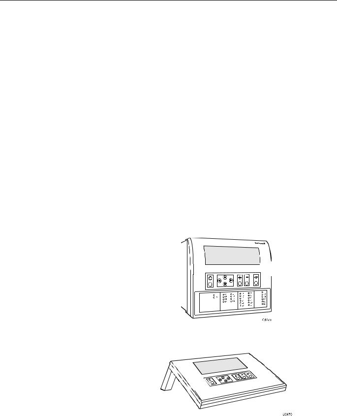
XI581/XI582 differences The XI581 (Fig. 1) and XI582 (Fig. 2) look and operate very much alike. The difference is that the XI581 mounts directly on the front of an Excel 500 or 600 Controller, while the XI582 is a desktop unit that you can place up to 50 ft. (15 m) away from an Excel controller or mount on a wall.
NOTE: Since they cannot be connected to a controller-mounted operator terminal, the Excel 500-XCL5010 and the Excel 800-XCL8010A are operable only with the XI582.
Fig. 1. XI581 Controller-Mounted Operator Terminal
Fig. 2. XI582 Desktop Operator Terminal
1 |
EN2B-0126GE51 R0309 |

INTRODUCTION |
XI581/XI582 BUSWIDE OPERATOR INTERFACE |
Manual Organization
Purpose This manual explains how to connect and operate the XI581/XI582.
Organization This manual is divided into the following sections, including this introductory section.
The Introduction section briefly describes the XI581/XI582 and highlights similarities and differences between the two operator terminal models.
The Getting Started section describes:
•XI582 connection to an Excel controller. (The XI581 is mounted directly on an Excel controller at installation time.)
•Buswide access mode.
•Display area description and keypad operations.
•Password access levels that determine whether you can view and/or modify information using the XI581/XI582.
The Everyday Operations section explains tasks that you might perform daily or weekly.
The Alphabetic Reference section explains tasks that you do not perform regularly or in any particular order. The tasks are arranged alphabetically for easy lookup.
Appendix A: Hardware Setup describes how to route the cable for an XI582 that does not mount on the wall or an Excel controller.
The Index provides page number references to topics.
EN2B-0126GE51 R0309 |
2 |

XI581/XI582 BUSWIDE OPERATOR INTERFACE
GETTING STARTED
About this section |
This section describes: |
|
• Connection options |
|
• Screen display after start-up |
|
• Description of display window and keypad operations |
|
• Password access levels that determine the information you can view and/or |
|
modify |
Ratings
Electrical Input Class 2 power supply
Temperature The XI581/XI582 are suitable for use in ambient temperatures of up to 45 °C.
NOTE: The XI582/XI582 must be connected only to Excel 50/100/500/600/800 Controllers.
Connection Options
Connecting the XI581 |
The XI581 mounts on the front of an Excel 500-XC5010x and Excel 600-XC6010 |
|
||||||
|
Controller at installation time and requires no further connection. When the |
|
||||||
|
controller is powered, the XI581 is also powered. If the controller is off and then |
|
||||||
|
powered on, the XI581 displays a message about the power failure. Use the Cancel |
|
||||||
|
key (C) to acknowledge the message. The next screen is the main menu. See |
|
||||||
|
"Screen Displays" (page 9) for details. |
|
|
|
||||
Connecting the XI582 |
The XI582 requires the connection and routing of an appropriate cable (see Table |
|
||||||
|
1). If your XI582 does not already have a connected cable, see Appendix A: |
|
||||||
|
Hardware Setup, and Excel 500 Installation Instructions (EN1R-1047GE51) or Excel |
|
||||||
|
100C Installation Instructions (EN1R-0144GE51) or Excel 800 Installation |
|
||||||
|
Instructions (EN1B-0375GE51) for connection details. |
|
|
|
||||
|
|
|
|
|
Table 1. Controllers and Compatible Cables |
|
|
|
|
|
|
|
|
|
|
|
|
|
|
|
cable |
|
controllers |
|
length |
|
|
|
|
XW564 |
|
Excel 500 (prior to XC5010C CPU), 600; |
|
7 ft. (2.5 m) |
|
|
|
|
|
|
with strain relief |
|
|
|
|
|
|
XW565 |
|
Excel 500 (prior to XC5010C CPU), 600; without |
|
16 ft. (5 m) |
|
|
|
|
|
|
strain relief |
|
|
|
|
|
|
XW582 |
|
Excel 50, Excel 100C (front connector), Excel 500 |
|
16 ft. (5 m) |
|
|
|
|
|
|
(XC5010C CPU, front connector) (XCL5010 CPU, |
|
|
|
|
|
|
|
|
serial connector) |
|
|
|
|
|
|
XW5831 |
|
Excel 100C (rear terminals),Excel 500 (XC5010C |
|
16 ft. (5 m) |
|
|
|
|
|
|
CPU, rear connector) |
|
|
|
|
|
|
XW584 |
|
Adapter cable for XW582 to Excel 100B, 500 (older |
|
6 in. (16 cm) |
|
|
|
|
|
|
CPUs), 600 |
|
|
|
|
|
|
XW8822 |
|
Excel 800 Controller Module (XCL8010A), RJ45 jack |
|
16 ft. (5 m) |
|
|
|
|
XW884 |
|
Adapter cable from XW882 to 9-pin Sub-D front |
|
6 in. (16 cm) |
|
|
|
|
|
|
connector of Excel 50/100C, XC5010C, XCL5010 |
|
|
|
|
|
|
1Use this cable if the XI582 is to be permanently connected to an Excel 100C. |
|
||||
|
|
|
With the XW582 connected, the cover of the Excel 100C cannot be closed. |
|
||||
2In lieu of the XW882 cable, it is possible to use an XW582 connected with an XW586.
3 |
EN2B-0126GE51 R0309 |

GETTING STARTED |
XI581/XI582 BUSWIDE OPERATOR INTERFACE |
When the operator terminal has a connected cable, you can move it to any controller and attach it. If the controller has buswide capability, you can leave the XI582 attached to it and then access other controllers on the bus via remote login.
For information about connecting to various controllers, see below. After connection, see "Screen Displays" (page 9) for details on XI582 screen displays.
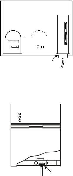
•Excel 100C Controllers have a RS232 serial port connection at the bottom of the device as shown in the following diagram. An additional serial port connection is provided at the terminals on the base of the Excel 100C. A port selector switch is located on the front to select front or rear port (see below).
IMPORTANT
It is imperative that the Excel 100C Controller’s port selector switch be properly set. Thus, after having operated an MMI via the front port, the switch has to be set back to its left position to reactivate a modem being connected to the rear terminals. If the switch is set to “front port“, the rear terminals are deactivated, and vice versa.
•Excel 500 and 600 Controllers have the serial port connection at the top of the controller as shown in the following diagram.
|
SERIAL |
|
|
PORT |
|
|
FRONT PORT |
|
|
ACTIVE |
|
|
REAR |
|
|
TERMINALS |
|
|
ACTIVE |
|
|
C6982b |
|
PORT SERIAL |
REAR TERMINALS FOR |
|
EXCEL 100C SELECTOR PORT |
MODEM OR MMI CONNECTION |
|
EXCEL 500/600 CONNECTION |
||
CONNECTION |
Fig. 3. Excel 100C and Excel 500/600 MMI connection
•The XC5010C CPU for Excel 500 has an additional serial port connection at the terminal block on the back of the unit and a switch on the front to select front or rear port.
Fig. 4. Excel 500-XC5010C MMI connection
•Excel 50 and Excel 500-XCL5010 Controllers require the XW582 cable which connects to the serial port on the bottom of the device as shown below.
EN2B-0126GE51 R0309 |
4 |
XI581/XI582 BUSWIDE OPERATOR INTERFACE |
|
|
GETTING STARTED |
||||||||||||||||||||||||||||||||||||||||
|
|
|
|
|
|
|
|
|
|
|
|
|
|
|
|
|
|
|
|
|
|
|
|
|
|
|
|
|
|
|
|
|
|
|
|
|
|
|
|
|
|
|
|
|
|
|
|
|
|
|
|
|
|
|
|
|
|
|
|
|
|
|
|
|
|
|
|
|
|
|
|
|
|
|
|
|
|
|
|
|
|
|
|
|
|
|
|
|
|
|
|
|
|
|
|
|
|
|
|
|
|
|
|
|
|
|
|
|
|
|
|
|
|
|
|
|
|
|
|
|
|
|
|
|
|
|
|
|
|
|
|
|
|
|
|
|
|
|
|
|
|
|
|
|
|
|
|
|
|
|
|
|
|
|
|
|
|
|
|
|
|
|
|
|
|
|
|
|
|
|
|
|
|
|
|
|
|
|
|
|
|
|
|
|
|
|
|
|
|
|
|
|
|
|
|
|
|
|
|
|
|
|
|
|
|
|
|
|
|
|
|
|
|
|
|
|
|
|
|
|
|
|
|
|
|
|
|
|
|
|
|
|
|
|
|
|
|
|
|
|
|
|
|
|
|
|
|
|
|
|
|
|
|
|
|
|
|
|
|
|
|
|
|
|
|
|
|
|
|
|
|
|
|
|
|
|
|
|
|
|
|
|
|
|
|
|
|
|
|
|
|
|
|
|
|
|
|
|
|
|
|
|
|
|
|
|
|
|
|
|
|
|
|
|
|
|
|
|
|
|
|
|
|
|
|
|
|
|
|
|
|
|
|
|
|
|
|
|
|
|
|
|
|
|
|
|
|
|
|
|
|
|
|
|
|
|
|
|
|
|
|
|
|
|
|
|
|
|
|
|
|
|
|
|
|
|
|
|
|
|
|
|
|
|
|
|
|
|
|
|
|
|
|
|
|
|
|
|
|
|
|
|
|
|
|
|
|
|
|
|
|
|
|
|
|
|
|
|
|
|
|
|
|
|
|
|
|
|
|
|
|
|
|
|
|
|
|
|
|
|
|
|
|
|
|
|
|
|
|
|
|
|
|
|
|
|
|
|
|
|
|
|
|
|
|
|
|
|
|
|
|
|
|
|
|
|
|
|
|
|
|
|
|
|
|
|
|
|
|
|
|
|
|
|
|
|
|
|
|
|
|
|
|
|
|
|
|
|
|
|
|
|
|
|
|
|
|
|
|
|
|
|
|
|
|
|
|
EXCEL 50
EXCEL 500-XCL5010 SERIAL PORT (REAR VIEW)
Fig. 5. Excel 50 and Excel 500-XCL5010 MMI connection
•Excel 10 Zone Manager and Excel 100B Controllers have a serial port connection at the bottom of the device as shown in the following diagram. The XI581/XI582 reads the data for the Excel 10 Controllers that connect to the Excel 10 Zone Manager.
|
ZM-Con a |
EXCEL 10 |
SERIAL |
ZONE MANAGER |
PORT |
AND EXCEL 100B
CONNECTION
Fig. 6. Excel 10 Zone Manager and Excel 100B MMI connection
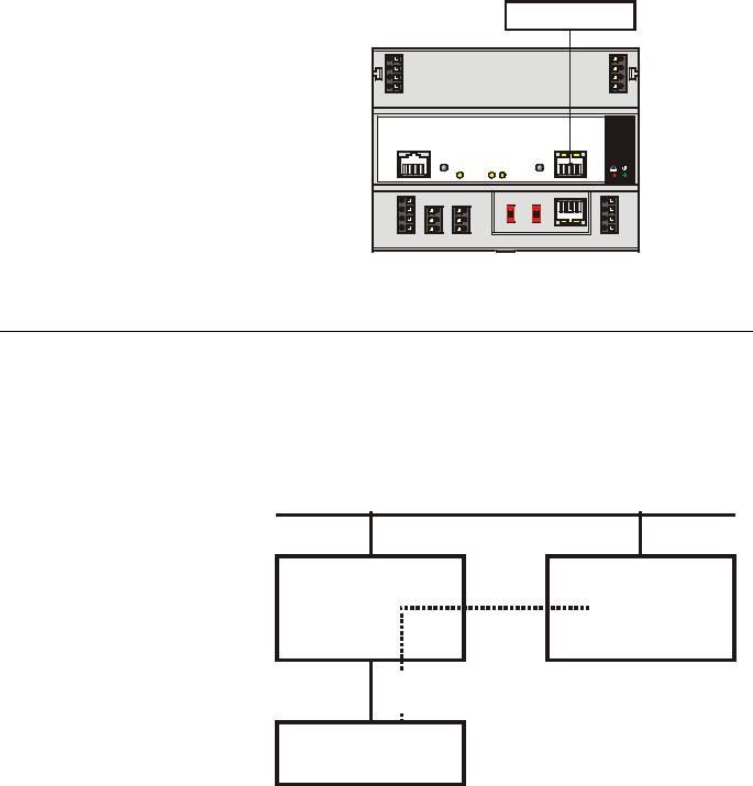
•The Excel 800 Controller Module (XCL8010A) features an RJ45 serial connection on the front (see Fig. 7) for connection (using the XW882 cable; alternately: the XW582 together with the XW586) of Human-Machine-Interfaces (HMIs).
5 |
EN2B-0126GE51 R0309 |
GETTING STARTED |
XI581/XI582 BUSWIDE OPERATOR INTERFACE |
HMI INTERFACE
71 COM a |
|
|
COM a 75 |
|
72 COM b |
|
|
COM b 76 |
|
73 |
24V~ |
|
|
24V~ 77 |
74 |
24V~0 |
|
|
24V~0 78 |
|
|
|
|
Honeywell |
|
LON |
C-BUS |
RESET |
PC/HMI |
87 654 3 21 |
|
|
8 765 43 21 |
|
|
|
|
|
! |
11 |
|
|
|
S1 |
S2 |
Modem |
1 |
||
|
|
|
|
|
|||||
12 |
8 |
5 |
9.6k |
all |
Panel |
|
|
2 |
|
76k |
mid |
|
|
||||||
13 |
9 |
6 |
LON |
87654321 |
3 |
||||
76k |
end |
||||||||
|
|
||||||||
|
|
|
|
|
|
|
|||
14 |
10 |
7 |
C-Bus |
I/O Bus |
Tx |
Rx |
4 |
||
LON |
C-Bus |
C-Bus |
Power/ |
||||||
|
|
|
|
|
|||||
|
in |
out |
|
|
|
|
|
Alarm |
|
Fig. 7. Excel 800 Controller Module and MMI connection
Buswide Access Mode
The buswide access mode allows communication between an XI581/XI582 and an Excel controller that is not directly connected to the XI581/XI582. Communication can include reading from and writing to the remote controller as well as receiving alarm status information.
For example, an XI581/XI582 attached to an Excel 500 Controller can log in to an Excel 100 Controller connected to the same system bus as the Excel 500 Controller.
C-bus
local |
|
remote |
Excel |
|
Excel |
controller |
|
controller |
|
|
|
 buswide
  access
XI581 / XI582
Fig. 8. Buswide access mode
Connection capabilities depend on the version of the controller and whether it has buswide access mode software. Table 2 specifies the versions capable of the buswide access mode.
EN2B-0126GE51 R0309 |
6 |
XI581/XI582 BUSWIDE OPERATOR INTERFACE |
GETTING STARTED |
There are two buswide access modes (active and passive) for controllers that have this capability.
•With active buswide access, a controller (for example, Controller A) can access another controller (Controller B) on the same bus if Controller B has at least passive access.
C-bus
Controller A |
|
Controller B |
active |
|
active or passive |
buswide access |
|
buswide access |
|
|
|
 buswide
  access
XI581 / XI582
Fig. 9. Active buswide access
•With only passive buswide access mode, a controller (for example, Controller B) cannot access another controller (Controller A) on the same bus. However, since Controller B has at least the passive buswide access mode, Controller B can be accessed by another controller that has the active buswide access mode (in this case, Controller A).
C-bus
Controller A |
X |
Controller B |
|
active |
|||
passive buswide |
|||
buswide |
|||
access, only |
|||
access |
|||
|
|
||
|
|
|
XI581 / XI582
Fig. 10. Passive buswide access
To access a remote controller, you must first log in to the controller. Once you are logged into the remote controller, operation is almost the same as operating a local controller. The menu structure used for operation is always that of the remote controller.
7 |
EN2B-0126GE51 R0309 |

GETTING STARTED |
XI581/XI582 BUSWIDE OPERATOR INTERFACE |
You cannot perform the following tasks while in the buswide access mode:
•Set the controller number.
•Set the communication baud rate.
•Start up a new controller.
Controller versions Some controller models (mainly older versions) do not support buswide functionality or support passive buswide functionality only after installation of a Firmware EPROM upgrade kit. Please contact your local branch or affiliate for further information on EPROM upgrade kits.
Table 2. Buswide Access Capability of Different Devices
|
device |
buswide access mode |
Excel 50, 100, 500, 600, |
Yes, with Firmware EPROM Version Excel |
|
800 Controller |
500/600/800 1.03.00 or newer.1 |
|
|
|
Version 1.01 cannot support the active access mode.2 |
Excel 20 |
Controller |
Passive buswide access mode, only. |
Excel 10 |
Zone Manager |
Excel 10 Zone Manager supports the passive buswide |
|
|
access mode only with Firmware EPROM Version |
|
|
1.02.xx or newer3. |
XIP100 |
|
no |
1Excel 100/500/600 Controllers running under Firmware EPROM Version Excel 500/600 1.2.XX can be upgraded by changing the Firmware EPROM to Version 1.03. The controllers then support full buswide functionality, i.e. passive and active buswide access. Excel 800 controllers support this with any firmware version, starting with 3.00.xx.
2Excel 100/500/600 Controllers running under Firmware EPROM Version Excel 500 Version 1.01 must be equipped with the Excel 1.01 upgrade kit for the buswide access mode. They then support the passive buswide access mode. However, Version 1.01 Controllers do not support the active buswide access mode.
3Excel 800 controllers support this with any firmware version, starting with 3.00.xx.
Buswide alarms The XI581/XI582 does not directly report buswide alarms on screen, but you can set it to an “alarm standby” mode where it listens to the system bus and then reports the occurrence of a new alarm somewhere on the system bus. In a separate screen, you can view the contents of the alarm buffer which will tell you where on the system bus the new alarm has occurred. You can then log in to the appropriate controller and look in the alarm buffer of the remote controller to find the cause of the alarm.
To enable the buswide alarm flag, set the XI581/XI582 to Alarm Standby Flag mode in the 'Buswide Access' screen. To enable receiving of buswide alarms, set the XI581/XI582 to 'Alarm Standby On'. The "Alarm Information" section describes these options.
When alarm standby is on and the alarm flag enabled, a screen symbol starts flashing as soon as a new buswide alarm arrives from somewhere on the system bus.
NOTE: Local alarms will not show when you are logged in to a remote controller.
The reading of a buswide alarm from an XI581/XI582 is independent of the XBS/XBS-i/XFI/EBI mechanism for alarm acknowledgment.
Performance Only one buswide XI581/XI582 (local or remote) can be logged onto a controller at any one time. However, there is no restriction as to the total number of buswide XI581/XI582 used on the same system bus. When XBS PCs are also on the bus, there may be up to four XBS PCs on the same bus and one buswide XI581/XI582 that is in remote access at the same time.
All XI581/XI582 are of equal priority, so that whichever device signs on first gains access to a controller and no other device (local or remote) can sign on to the same controller during this time.
EN2B-0126GE51 R0309 |
8 |

XI581/XI582 BUSWIDE OPERATOR INTERFACE |
GETTING STARTED |
Screen Displays
Initial screen displays depend on the status of the controller and its pending alarms.
Powered controller After you plug an XI582 into a powered controller, the main menu appears in the display window.
An XI581 that is always attached to a controller typically displays the main menu unless an operator has penetrated to some other menu.
Controller power-on The first display screen that appears after power-on is a message about the power failure. Use the Cancel key (C) to acknowledge the message. The main menu is displayed.
CPU reset If you press the controller's CPU reset switch, the controller restarts and the XI581/XI582 displays the 'title/copyright' screen.
Memory Cleared
If you push the CPU reset switch, everything in the controller is deleted. Use the CPU reset switch only for servicing.
To reload the controller, follow the download procedure as explained in the Flash EPROM and RAM Management procedures (in the "ALPHABETIC REFERENCE" section). If the controller does not have Flash EPROM, use Excel CARE software to download the controller.
Adjusting contrast The contrast of the display can be adjusted, using a screwdriver, by rotating the corresponding knob accessible through a hole at the rear of the device. Pressing any of the eight operating keys activates the backlight. If no entries are made for approximately ten minutes, the backlight turns itself off automatically until a key is pressed again.
Operation The rest of this section describes the XI581/XI582 display area and its access levels. If you are familiar with this information, continue with the sign-on procedure in the "Local and Remote Sign-On and Sign-Off " section.
9 |
EN2B-0126GE51 R0309 |
GETTING STARTED |
XI581/XI582 BUSWIDE OPERATOR INTERFACE |
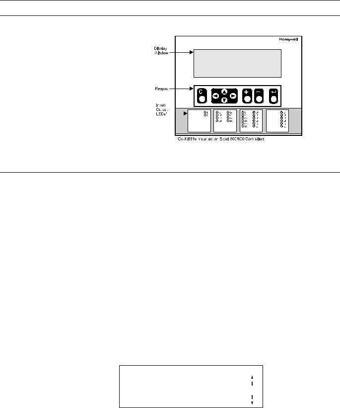
Display Area Description
Fig. 11. MMI display area
Display Window
The XI581/XI582 display window is located above the keypad. The window presents system information, operator entries, and menus of functions that you can perform.
Menu example For example, the following is the first menu (the main menu) that appears. It shows the controller name, the current time and date, and a list of functions you can select. The word Password is highlighted (reverse video on the display) because it is the default selection.
CONTROLLER_07 |
18:16! |
||
Running |
Alarms |
15.12.1994 |
|
Password |
|
|
|
Time Programmes |
Trend Buffer |
||
Data Points |
System Clock |
||
|
|
System Data |
|
|
|
|
|
The buswide alarm flag (exclamation mark, !, in the top right-hand corner of the window) indicates that the buswide alarm notification mode is enabled. If it is blinking, an alarm has occurred. The "Alarm Information" section describes alarm display and acknowledgment.
Time program window example The following window display appears when you select 'Time Programmes'. It lists the zones that have time programs and waits for operator selection of a zone. The scroll bar is on the right-hand side of the window.
Time Programme
Time Program 1 |
|
|
Ventil. Sys |
|
|
Lighting |
1 |
|
Heating zone east |
|
|
Heating zone west |
|
|
EN2B-0126GE51 R0309 |
10 |

XI581/XI582 BUSWIDE OPERATOR INTERFACE |
GETTING STARTED |
Scroll bar The XI581/XI582 display window can show six lines of information at a time. A scroll bar appears on the right-hand side of the window as shown in the 'Time Programme' window example:
1
The scroll bar allows you to quickly move through the items in the list so you can locate the one you want. The number indicates the number of pages being scrolled using the right and left arrow keys. Use the following keys to scroll (see Table 3).
NOTE: With an Excel 50 directly connected or accessed via the buswide access mode, the display varies from that given for an Excel 100/500/600 controller. The left two-thirds show the MMI information of the Excel 50; the right third shows text equivalents of the four fast-access keys of the Excel 50 (see example below).
|
|
|
|
|
|
AHU |
|
PLANT |
|
|
|
|
|
|
|
TUE 21:09 11:55 |
TIME |
|
|
|
|
|
|
|
|
to 06:00 20.0 C |
PARAMETERS |
|
|
|
|
|
|
|
|
TODAY |
NEXT |
ALARM |
|
|
|
|
|
|
|
|
|
|
|
|
|
|
|
|
|
|
Table 3. Scroll Key Descriptions |
||
|
|
|
|
|
|
|
|
|
|
key |
|
key name |
|
scroll description |
|||||
|
|
|
|
|
|
right arrow |
Move forward the selected number of pages. See the plus and |
||
|
|
|
|
|
|
|
minus key descriptions to select the number of pages. The default |
||
|
|
|
|
|
|
|
is 1 page. |
|
|
|
|
|
|
|
|
|
|
||
|
|
|
|
|
|
left arrow |
Move backward the selected number of pages. See the plus and |
||
|
|
|
|
|
|
|
minus key descriptions to select the number of pages. The default |
||
|
|
|
|
|
|
|
is 1 page. |
|
|
|
|
|
|
|
|
|
|
||
|
|
|
|
|
|
plus |
Increment the number in the scroll bar by 1 (maximum 9). For |
||
|
|
|
|
|
|
|
example, select 2 to scroll two pages. |
||
|
|
|
|
|
|
|
After selecting the number of pages, use the right arrow key to |
||
|
|
|
|
|
|
|
scroll the pages forward. |
||
|
|
|
|
|
|
minus |
Decrement the number in the scroll bar by 1. |
||
|
|
|
|
|
|
|
After selecting the number of pages, use the right arrow key to |
||
|
|
|
|
|
|
|
scroll the pages backwards. |
||
|
|
|
|
|
|
|
If you press the minus key while the number in the scroll bar is 1, a |
||
|
|
|
|
|
|
|
Less-Than symbol (<) appears. If you then press the left arrow key, |
||
|
|
|
|
|
|
|
the first page in the list will be displayed. |
||
|
|
|
|
|
|
|
If you press the minus key again while the Less-Than symbol is in |
||
|
|
|
|
|
|
|
the scroll bar, a Greater-Than symbol (>) appears. If you then |
||
|
|
|
|
|
|
|
press the right arrow key, the last page in the list will be displayed. |
||
The next section describes the other keys available on the keypad as well as other functions for the right arrow, left arrow, plus, and minus keys.
11 |
EN2B-0126GE51 R0309 |

GETTING STARTED |
XI581/XI582 BUSWIDE OPERATOR INTERFACE |
Keypad
The XI581/XI582 keypad has eight keys that control all operator entries. The following table describes the function of each key. Following the table are tips for moving the cursor around within the display window.
|
|
Table 4. Description of Key Functions |
|
|
|
|
|
key |
key name |
description |
|
|
Cancel |
End the task you are performing and return to a previous display |
|
|
|
window. |
|
|
|
If you press this key after you modify a field, but before pressing |
|
|
|
Enter, , the XI581/XI582 erases any new information you input |
|
|
|
and retains the original information. |
|
|
|
If you press this key after you modify a field and press Enter, , the |
|
|
|
XI581/XI582 retains the new information you input. |
|
|
left arrow |
Within a menu or a line of items, the left arrow moves the cursor |
|
|
|
from one column (or item) to another. |
|
|
|
Within a data field, the left arrow moves the cursor to the left one |
|
|
|
digit. |
|
|
|
|
|
|
right arrow |
Within a menu or a line of items, the right arrow moves the cursor |
|
|
|
from one column (or item) to another. |
|
|
|
Within a data field, the right arrow moves the cursor to the right one |
|
|
|
digit. |
|
|
|
|
|
|
down arrow |
Move the cursor to the next field, the next column, or to the next |
|
|
|
line in a column. |
|
|
|
|
|
|
up arrow |
Move the cursor to the previous field, the previous column, or to the |
|
|
|
previous line in a column. |
|
|
|
|
|
|
plus |
Increase the value of a digit by one (for example, from 2 to 3). You |
|
|
|
can also use this key to change the condition of a digital point. For |
|
|
|
example, press this key to flip a digital point from OFF to ON. |
|
|
|
|
|
|
minus |
Decrease the value of a digit by one (for example, from 2 to 1). You |
|
|
|
can also use this key to change the condition of a digital point. For |
|
|
|
example, press this key to flip a digital point from OFF to ON. |
|
|
Enter |
Enter and confirm input values or command choices for the |
|
|
|
controller. When you press this key, it allow modification of the |
|
|
|
highlighted field. Pressing Enter ( ) again stores the value in |
|
|
|
memory. |
|
Moving between columns To move horizontally between columns in a menu or list, press the down arrow key until you reach the bottom of the column. When you press the down arrow key again, the cursor automatically jumps to the first item in the next column.1
If the cursor is on the first item in the first column, pressing the right arrow key moves the cursor to the first item in the second column. If the cursor is on the last item in the second column, pressing the down arrow key moves the cursor to the first item in the first column.1
1 NOTE:In case not all entries are displayed (e.g. no password entered), this may differ slightly.
Modifying a field To change information in a field, first use the arrow keys to move to and highlight the field. Then press Enter, . After the change is made, Enter ( ) must be pressed again to confirm the change.
EN2B-0126GE51 R0309 |
12 |

XI581/XI582 BUSWIDE OPERATOR INTERFACE |
GETTING STARTED |
Moving from field to field Once you begin modifying the digits in a field, you can move from digit to digit within that field using the arrow keys.
However, to move to a different field, you must press Enter, , after making your last change to the field. The field is then highlighted. You can then use the arrow keys to move to and highlight the next field you wish to modify.
Point order in lists Points are listed according to hardware type. In other words, all analog points appear first, followed by digital points, and finally totalizer points.
Display of "****" The string "****" means that no value is available.
Operator Access Levels
There are three access levels that control operator access to XI581/XI582 information. The access levels determine the information an operator can view and which tasks an operator can perform.
Access level 1 Access level 1 is available to all operators and does not require a password. At level 1, you can view some, but not all, of the information programmed into the controller. You cannot modify any data. Specifically, access level 1 allows you to view the following:
•Time program information
•Point descriptions
•System clock
•Trend log
•Alarm information
•Buswide information
Passwords To operate at level 2 or 3, an operator must enter a password. Passwords are four numerical characters and are controlled by the site administrator. The "Level 2/3 Password Entry" section explains how to enter your password.
Access level 2 Access level 2 allows you to view all information accessible to level-1 operators. In addition, you can modify time programs, set the system clock, and view totalizer information. You can also view and modify information in other controllers on the same system bus.
Access level 3 Access level 3 allows you to perform all tasks accessible to level-1 and level-2 operators. In addition, you can:
•Modify point descriptions
•Reset totalizers
•Modify parameters
•Change setpoints
This access level should be reserved for only those users who are responsible and competent in HVAC engineering, such as a commissioning engineer. This is to avoid incorrect operation of the plant. This access level is required for setting the access levels of the other users.
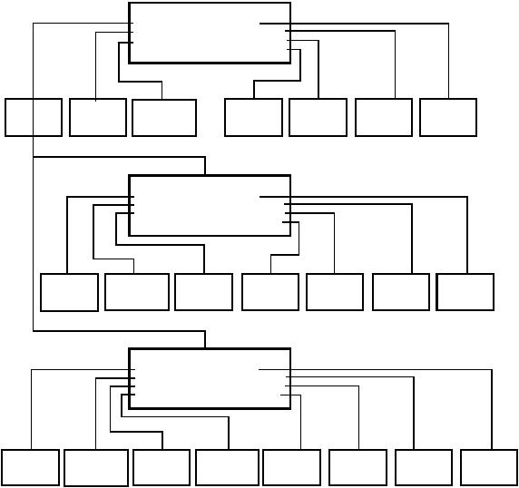
Access level chart The following chart summarizes the functions available at each access level.
13 |
EN2B-0126GE51 R0309 |
GETTING STARTED |
|
XI581/XI582 BUSWIDE OPERATOR INTERFACE |
CONTROLLER_01 |
ACCESS LEVEL 1 |
|
PASSWORD |
ALARMS |
LOWEST ACCESS |
|
||
TIME PROGRAM |
TREND BUFFER |
|
DATA POINTS |
SYSTEM CLOCK |
|
|
SYSTEM DATA |
|
ENTER |
|
VIEW |
|
VIEW |
|
|
VIEW |
|
VIEW |
VIEW |
VIEW |
|
TIME |
|
DATA POINT |
|
|
SYSTEM |
|
SYSTEM |
TREND |
||
PASSWORD |
|
|
|
|
|
ALARMS |
|||||
|
PROGRAM |
|
DESCRIPTION |
|
|
DATA |
|
CLOCK |
LOG |
||
|
|
|
|
|
|
|
|||||
|
|
|
|
|
|
|
|
|
|
|
|
|
|
|
|
|
|
VIEW BUSWIDE |
|
|
|
||
|
|
|
|
|
|
|
|
|
|||
|
|
|
|
|
|
|
DATA |
|
|
|
|
|
|
|
|
CONTROLLER_01 |
|
ACCESS LEVEL 2 |
|||||
|
|
|
|
TIME PROGRAM |
ALARMS |
|
|||||
|
|
|
|
|
|
|
|||||
|
|
|
|
DATA POINTS |
TREND BUFFER |
|
|
|
|||
|
|
|
|
TOTALIZERS |
SYSTEM CLOCK |
|
|
|
|||
|
|
|
|
|
|
SYSTEM DATA |
|
|
|
||
|
|
MODIFY |
|
|
VIEW |
|
|
|
VIEW |
|
|
|
|
VIEW |
|
|
|
SET |
|
|
VIEW |
|
|
|
VIEW |
|
|||||||||
|
|
|
TIME |
|
DATA POINT |
|
|
|
|
|
|
SYSTEM |
|
|
SYSTEM |
|
|
TREND |
|
|
|
||||||||||||||
|
|
|
|
|
|
TOTALIZERS |
|
|
|
|
|
|
|
|
ALARMS |
|
|||||||||||||||||||
|
PROGRAM |
|
DESCRIPTION |
|
|
|
|
|
DATA |
|
|
CLOCK |
|
|
LOG |
|
|
|
|
||||||||||||||||
|
|
|
|
|
|
|
|
|
|
|
|
|
|
|
|
|
|
|
|
|
|
||||||||||||||
|
|
|
|
|
|
|
|
|
|
|
|
|
|
|
|
|
|
|
|
|
|
|
|
|
|
|
|
|
|
|
|
|
|||
|
|
|
|
|
|
|
|
|
|
|
|
|
|
|
|
|
|
BUSWIDE ACCESS |
|
|
|
|
|
|
|
||||||||||
|
|
|
|
|
|
|
|
|
|
|
|
|
|
|
|
|
|
|
|
|
|
|
|
|
|||||||||||
|
|
|
|
|
|
|
|
|
|
|
|
|
|
|
|
|
|
FLASH EPROM |
|
|
|
|
|
|
|
|
|
|
|
|
|||||
|
|
|
|
|
|
|
|
|
|
CONTROLLER_01 |
|
|
|
|
|
|
|
|
|
|
|
|
ACCESS LEVEL 3 |
||||||||||||
|
|
|
|
|
|
|
|
|
TIME PROGRAM |
|
ALARMS |
|
|
|
|
|
|
|
|
|
|
|
HIGHEST ACCESS |
||||||||||||
|
|
|
|
|
|
|
|
|
|
|
|
|
|
|
|
|
|
|
|
|
|
|
|
|
|
|
|||||||||
|
|
|
|
|
|
|
|
|
DATA POINTS |
|
|
TREND BUFFER |
|
|
|
|
|
|
|
|
|
|
|
|
|||||||||||
|
|
|
|
|
|
|
|
|
TOTALIZERS |
|
|
|
SYSTEM CLOCK |
|
|
|
|
|
|
|
|
|
|
|
|
||||||||||
|
|
|
|
|
|
|
|
|
PARAMETERS |
|
|
SYSTEM DATA |
|
|
|
|
|
|
|
|
|
|
|
|
|||||||||||
|
|
|
|
|
|
|
|
|
|
|
|
|
|
|
|
|
|
|
|
|
|
|
|
|
|
|
|||||||||
MODIFY |
|
|
MODIFY |
|
|
RESET |
|
|
MODIFY |
|
|
MODIFY |
|
|
SET |
|
VIEW |
|
VIEW |
||||||||||||||||
TIME |
|
|
DATA POINT |
|
|
|
|
|
|
SYSTEM |
|
|
SYSTEM |
TREND |
|
||||||||||||||||||||
|
|
|
|
TOTALIZERS |
|
PARAMETERS |
|
|
|
|
ALARMS |
||||||||||||||||||||||||
PROGRAM |
|
|
DESCRIPTION |
|
|
|
DATA |
|
|
CLOCK |
|
LOG |
|
||||||||||||||||||||||
|
|
|
|
|
|
|
|
|
|
|
|
|
|
|
|
|
|
|
|
|
|||||||||||||||
|
|
|
|
|
|
|
|
|
|
|
|
|
|
|
|
|
|
|
|
|
|
|
|
|
|
|
|
|
|
||||||
|
|
|
|
|
|
|
|
|
|
|
|
|
|
|
|
|
|
|
|
|
BUSWIDE ACCESS |
|
|
|
|
|
C6992-2 |
||||||||
|
|
|
|
|
|
|
|
|
|
|
|
|
|
|
|
|
|
|
|
|
|
|
|
|
|
||||||||||
|
|
|
|
|
|
|
|
|
|
|
|
|
|
|
|
|
|
|
|
FLASH EPROM |
|
|
|
|
|
|
|
||||||||
Fig. 12. Operator access level and corresponding functions of XI581/XI582
EN2B-0126GE51 R0309 |
14 |
XI581/XI582 BUSWIDE OPERATOR INTERFACE |
GETTING STARTED |
15 |
EN2B-0126GE51 R0309 |

XI581/XI582 BUSWIDE OPERATOR INTERFACE
EVERYDAY OPERATIONS
About this section This section details steps for common everyday procedures. The procedures are grouped by common functions as follows.
Local and Remote Sign-on and Sign-off
•Level-2 and level-3 password entry
•Logging into a remote controller
•Logging off from a remote controller
•Signing off from a controller (local or remote)
•Alarm Information
•Viewing alarm information
•Viewing buswide alarms
•Enabling/disabling the buswide alarm mode and alarm flag
•Acknowledging the buswide alarm flag
Viewing point information
Reviewing time program schedules
Requesting a trend log in tabular or graphic format
Listing status of totalizer points
Controller information
•Reading controller date and time
•Viewing controller configuration data
All these procedures, except listing totalizer status, are level-1 operator tasks. The totalizer function is a level-2 or level-3 operator task.
Any procedures requiring access to a remote controller require log-in to that controller.
Point vs. data point Note that XI581/XI582 refers to points as “data points”. This document uses the term “point” except when the expression “data point” appears in XI581/XI582 screen displays. EXCEL 5000™ literature generally uses the term “points”. The terms have the same meaning.
See also the "ALPHABETIC REFERENCE" section (page 49) for other procedures that you may use less frequently.
Local and Remote Sign-On and Sign-Off
Because the XI581/XI582 is powered whenever the controller it is connected to is powered, there is no “sign-on” and “sign-off” as for other types of operator terminals. Typically, when you plug an XI582 into a powered controller, the main menu will be displayed and you can begin selecting level-1 functions. Alternatively, you can enter a password to obtain access to level-2 or level-3 functions.
The following are descriptions of the types of screen displays that occur depending on the status of the controller (powered or reset) and its alarms.
Powered controller When you plug an XI582 into a powered controller, the main menu appears in the display window.
A XI581 that is always attached to a controller typically displays the main menu unless an operator has penetrated to some other menu. You can press Cancel (C) repeatedly until the main menu is displayed.
16 |
EN2B-0126GE51 R0308 |
XI581/XI582 BUSWIDE OPERATOR INTERFACE |
|
EVERYDAY OPERATIONS |
||||
Main menu (access level 1) |
|
|
|
|||
|
|
|
|
|
|
|
|
|
CONTROLLER_01 |
18:16! |
|
||
|
|
Running |
|
15.12.1994 |
|
|
|
|
Password |
|
Alarms |
|
|
|
|
Time Programmes |
Trend Buffer |
|
||
|
|
Data Points |
System Clock |
|
||
|
|
|
|
System Data |
|
|
Level 1 operators |
Level-1 operators do not have to enter a password. |
Level 2 & 3 operators |
Level-2 and level-3 operators must enter a password to perform level-2 and level-3 |
|
operations. See "Level 2/3 Password Entry" (page 17) for details. |
Controller power-on |
The first display screen that appears after power-on is a message about the power |
|
failure. Use the Cancel key (C) to acknowledge the message. The main menu will |
|
be displayed. |
Procedures |
This section describes the following procedures: |
|
• Level 2/3 password entry to enter a password if level-2 or level-3 functions are |
|
required |
|
• Logging into a remote controller to gain access to a controller that is not directly |
|
connected to the XI581/XI582 |
|
• Logging off from a remote controller to disconnect from a remote controller that |
|
you previously logged into |
|
• Signing off from a controller (local or remote) to return to the level-1 main menu. |
|
|
Level 2/3 Password Entry |
Purpose |
To sign on to an XI581/XI582 connected to a controller. |
|
Procedure |
1. After the XI581/XI582 is connected to a controller, the main menu automatically |
|
|
appears in the display window unless the controller is reset and needs to be |
|
|
downloaded. If the controller needs to be downloaded, the 'title/copyright' screen |
|
|
will be displayed. |
|
|
NOTE: |
If the main menu does not appear, press Cancel (C) until it does. |
|
RESULT: The main menu appears and lists information that level-1, -2, and -3 |
|
|
|
operators can view. The word Password is highlighted as the default |
|
|
selection. |
Level-2 and -3 operators |
2. Level-2 and level-3 operators do not have to enter a password to perform a |
|
|
level-1 task. However, to perform a level-2 or level-3 task, you must enter a |
|
|
password using the 'Password' function. Press Enter ( ) to select the 'Password' |
|
|
function. |
|
|
NOTE: |
If the 'Password' function is not highlighted, use the arrow keys to |
|
|
move to and highlight the item and then press Enter ( ). |
RESULT: XI581/XI582 asks for your password. The display window shows four asterisks where you enter your password.
Please enter your Password:
****
17 |
EN2B-0126GE51 R0309 |

EVERYDAY OPERATIONS |
|
XI581/XI582 BUSWIDE OPERATOR INTERFACE |
|
Password entry |
3. Press Enter () to select the password field (four asterisks). |
||
|
|
— The display window shows a 5 as the first, left-most digit of the password |
|
|
|
field. |
|
|
|
— If the first digit of your password is higher than 5, press the plus key (or the |
|
|
|
up arrow key) until the first digit of your password is correct. |
|
|
|
— If the first digit of your password is lower than 5, press the minus key (or the |
|
|
|
down arrow key) until the first digit of your password is correct. |
|
|
|
— Use the right arrow key to move the cursor to the second digit. Notice that |
|
|
|
the first digit becomes an asterisk again to maintain password privacy. |
|
|
|
Repeat this procedure until you have correctly input all digits in the password |
|
|
|
field. |
|
|
|
If you incorrectly input a digit, press Cancel (C) to start over again with the first, |
|
|
|
left-most digit. |
|
|
|
Once the password is input, press Enter ( ) to complete password entry. If the |
|
|
|
password is incorrect, software re-prompts for password entry. |
|
|
|
RESULT: If you correctly enter a password, the word Next will be displayed. |
|
|
|
For level-3 operators, the word 'Change' will also be displayed to |
|
|
|
allow you to change the password. See the "Passwords" section for |
|
|
|
the procedure to change a password. |
|
|
|
|
|
|
|
Please enter your Password: |
|
****
Change |
Next |
Press Enter ( ) to select Next.
RESULT: The display window shows the main menu appropriate for the password you entered.
NOTE: The main menu for access level 2 shows three items ('Time Programmes', 'Data Points', and 'Totalizers') in the left column, while the main menu for access level 3 shows four items ('Time Programmes', 'Data Points', 'Totalizers', and 'Parameters').
Main menu for access level 2
|
CONTROLLER_01 |
18:16 |
||
|
Running |
|
15.12.1994 |
|
|
Time Programmes |
|
Alarms |
|
|
Data Points |
|
Trend Buffer |
|
|
Totalizers |
System Clock |
||
|
|
|
System Data |
|
Main menu for access level 3
|
CONTROLLER_01 |
18:16 |
||
|
Running |
|
15.12.1994 |
|
|
Time Programmes |
|
Alarms |
|
|
Data Points |
|
Trend Buffer |
|
|
Totalizers |
System Clock |
||
|
Parameters |
System Data |
||
|
|
|
|
|
5.Select desired function. The rest of this manual contains procedure for each of the functions.
EN2B-0126GE51 R0309 |
18 |

XI581/XI582 BUSWIDE OPERATOR INTERFACE EVERYDAY OPERATIONS
|
Logging into a Remote Controller |
Purpose |
To initiate communication with a remote controller. |
Performance |
Only one buswide XI581/XI582 (local or remote) can be logged onto a controller at |
|
any one time. However, there is no restriction as to the total number of buswide |
|
XI581/XI582 used on the same system bus. When XBS PCs are also on the bus, |
|
there may be up to four XBS PCs on the same bus and one buswide XI581/XI582 |
|
that is in remote access at the same time. |
|
All XI581/XI582 Operator Terminals are of equal priority, so that whichever device |
|
signs on first gains access to a controller and no other device (local or remote) can |
|
sign on to the same controller during this time. |
Procedure |
1. Sign on to the XI581/XI582 at the desired user level (1, 2, or 3). See section |
|
"Level 2/3 Password Entry" (page 17) if you do not know how. |
|
2. At the main menu, use the arrow keys to move to and highlight System Data. |
|
Then press Enter ( ) to complete the selection. |
|
RESULT: The display window shows system data, including the 'Buswide |
|
Access' option. In the following example, note that the local controller |
|
is CONTROLLER_01. |
System Data
System Info
HW-Interface Config.
Flash EPROM
Buswide Access
NOTE: The 'Flash EPROM' item will be displayed only if you signed on as a level-3 operator.
3.Use the arrow keys to move to and highlight Buswide Access. Then press Enter ( ) to complete the selection.
RESULT: The display window lists the buswide access options you can choose.
Buswide Access
CONTROLLER_01
Remote Login Alarm Standby On
Logoff Alarm Standby Flag
Show All DevicesAlarm Standby Off
The option 'Logoff' appears below 'Remote Login' only if you have already logged in on the remote controller (i.e. a connection has been established). 'Logoff' can be used to sever the connection to the remote controller. See section "Logging Off from a Remote Controller" (page 21) for details.
4.Press Enter ( ) to select Remote Login (highlighted default).
RESULT: The display window lists all devices available for log-in. Controller name and number are shown for each device.
Remote Login
CONTROLLER_07 7 CONTROLLER_09 9
 1
1
19 |
EN2B-0126GE51 R0309 |

EVERYDAY OPERATIONS |
XI581/XI582 BUSWIDE OPERATOR INTERFACE |
5.Use the arrow keys to move to and highlight the name of the desired controller. Press Enter ( ) to complete the selection.
RESULT: After about 5 seconds, the level-1 main menu of the selected controller will be displayed unless there is a pending alarm. If an alarm is pending in the remote controller, the alarm will be displayed instead of the menu. Press Cancel (C) and log in again to see the remote controller’s main menu.
The following example shows the result of selecting
CONTROLLER_07.
|
CONTROLLER_07 |
18:16! |
||
|
Running |
|
15.12.1994 |
|
|
Password |
|
Alarms |
|
|
Time Programmes |
Trend Buffer |
||
|
Data Points |
System Clock |
||
|
|
|
System Data |
|
|
|
|
|
|
Excel 20 and Excel 50 Controllers
The operator interface for Excel 20 and Excel 50 Controllers has only four lines and varies considerably from the screens in this manual. If you log into a remote Excel 20 or Excel 50 Controller, see the appropriate Controller User Guide for operator interface description and details.
6.Press Enter ( ) to select Password.
RESULT: The 'Password' screen will be displayed.
Please enter your Password:
****
Change |
Next |
7.Press Enter ( ) to have the same access level as the local controller. To have a higher access level, type in your password and press Enter ( ).
RESULT: The main menu of the selected controller will be displayed. The following example shows level-3 access for CONTROLLER_07.
|
CONTROLLER_07 |
18:16 |
||
|
Running |
|
15.12.1994 |
|
|
Time Programmes |
|
Alarms |
|
|
Data Points |
|
Trend Buffer |
|
|
Totalizers |
System Clock |
||
|
Parameters |
System Data |
||
If the selected device is already being accessed (locally or remotely), the log-in fails and the system displays the message “Device logged”. Try again when the device is available.
8.Perform listed tasks as desired just as for a local controller. Log off from the remote controller when finished (see section "Logging Off from a Remote Controller", page 21, for details).
Buswide alarm flag If the buswide alarm flag was enabled on the local controller, the flag disappears after log-in to the remote controller. Set it for the remote controller again to reestablish it, if desired. See section "Alarm Information" (page 22) for procedures.
EN2B-0126GE51 R0309 |
20 |

XI581/XI582 BUSWIDE OPERATOR INTERFACE |
EVERYDAY OPERATIONS |
Logging Off from a Remote Controller
Purpose To disconnect from a remote controller.
Procedure 1. From the remote controller’s main menu, use the arrow keys to move to and highlight System Data. Then press Enter ( ) to complete the selection.
RESULT: The display window shows system data, including the 'Buswide Access' option.
System Data
System Info
HW-Interface Config.
Flash EPROM
Buswide Access
NOTE: The 'Flash EPROM' item will be displayed only if you signed on as a level-3 operator.
2.Use the arrow keys to move to and highlight Buswide Access. Then press Enter ( ) to complete the selection.
RESULT: The display window lists the buswide access options you can choose for remote CONTROLLER_07.
Buswide Access
CONTROLLER_07
Remote Login
Logoff
Show All Devices
3.Use the arrow keys to move to and highlight Logoff. Then press Enter ( ) to complete the selection.
RESULT: Software logs off CONTROLLER_07 and displays the 'Remote Login' menu screen to allow you to log in to another controller.
Remote Login
CONTROLLER_07 7
CONTROLLER_09 9 1
1
4.Select a remote controller to log into or press Cancel (C) to return to the 'Buswide Access' screen for the local controller.
Controller Sign Off
Purpose When you have finished using the XI581/XI582 Operator Terminal to access either a remote or local controller, sign off so no one else can access the controller at the same level that you accessed.
Sign-off To sign off, press Cancel (C) until the main menu appears with Password highlighted.
21 |
EN2B-0126GE51 R0309 |

EVERYDAY OPERATIONS |
XI581/XI582 BUSWIDE OPERATOR INTERFACE |
|||||
Main menu |
|
|
|
|||
|
|
|
|
|
|
|
|
|
CONTROLLER_01 |
18:16! |
|
||
|
|
Running |
|
15.12.1994 |
|
|
|
|
Password |
|
Alarms |
|
|
|
|
Time Programmes |
Trend Buffer |
|
||
|
|
Data Points |
System Clock |
|
||
|
|
|
|
System Data |
|
|
|
|
|
|
|
|
|
Auto sign-off If you are signed on to the XI581/XI582 and do not press any keys for 10 minutes, the operator terminal automatically signs you off.
Alarm Information
|
This section describes how to view alarm information from the local controller as |
||||
|
well as buswide alarms. For buswide alarms, the section describes how to set the |
||||
|
buswide alarm mode and acknowledge the buswide alarm flag. |
||||
|
|
|
|
|
|
|
|
|
|
Viewing Alarm Information |
|
Purpose |
To view selected alarm information, including the last 99 alarms, the controller has |
||||
|
generated and stored in memory, all current alarms (critical and non-critical), current |
||||
|
critical alarms, current non-critical alarms, and buswide alarms. All operators can |
||||
|
perform this task. |
||||
Select "Alarms" |
1. At the main menu, use the arrow keys to move to and highlight the Alarms |
||||
|
|
option. Press Enter ( ) to complete the selection. |
|||
|
|
RESULT: The 'View Alarms' screen displays options for viewing alarm |
|||
|
|
|
information. |
||
|
|
|
|
|
|
|
|
|
View Alarms |
|
|
|
|
|
Alarm Buffer |
|
|
|
|
|
All Points in Alarm |
|
|
|
|
|
Critical Points in Alarm |
|
|
|
|
|
Non Critical Points in Alarm |
|
|
|
|
|
Buswide Alarms |
|
|
|
|
|
|
||
Select desired option |
2. Use the arrow keys to move to and highlight the desired option: |
||||
EN2B-0126GE51 R0309 |
22 |

XI581/XI582 BUSWIDE OPERATOR INTERFACE |
|
|
EVERYDAY OPERATIONS |
||||||
|
|
|
Table 5. Alarm Buffer Options and Alarm Type Options |
||||||
|
|
|
|
|
|
|
|
|
|
|
alarm buffer option |
|
|
|
|
alarm type options |
|
|
|
|
Alarm Buffer is highlighted by default when the 'Alarms' |
|
Press the arrow keys to move to and highlight the desired |
|
|||||
|
screen is displayed. |
|
|
|
option (All Points in Alarm, Critical Points in Alarm, Non |
|
|||
|
Press Enter ( ) to select Alarm buffer. |
|
|
|
Critical Points in Alarm, or Buswide Alarms). Then press |
|
|||
|
|
|
|
Enter ( ) to complete the selection. |
|
|
|||
|
RESULT: The display window lists all alarms in controller |
|
RESULT: |
The display window lists points (all, critical, or |
|
||||
|
memory. |
|
|
|
|
non critical) currently in alarm. |
|
||
|
|
|
|
|
|
|
|
|
|
|
Alarm Buffer |
|
|
|
All Points in Alarm: |
|
|
||
|
19.07.93 16:35 Exhaust_fan |
|
|
|
Exhaust_fan |
|
|
||
|
19.07.93 06:26 Cafe_room_temp |
|
|
|
Cafe_room_temp |
1 |
|
||
|
18.07.93 23:57 Window_contact_17 1 |
|
Window_contact_17 |
|
|||||
|
18.07.93 16:07 Conf_room_temp |
|
|
|
Conf_room_temp |
|
|
||
|
17.07.93 20:17 Htg._zone_pump_1 |
|
|
|
Htg._zone_pump_1 |
|
|
||
|
|
|
|
|
|
|
|
|
|
|
|
|
|
|
|
|
|||
|
First column—The date the controller generated the alarm. |
|
NOTE: Alarm memory can contain 99 entries. All alarms |
|
|||||
|
The date appears in Date.Month.Year (DD.MM.YY) |
|
may not be able to appear in the display window at |
|
|||||
|
notation where DD=1-31, MM=1-12, and YY=the last |
|
the same time. To view alarms that do not display, |
|
|||||
|
two digits of the year. |
|
|
|
press the right arrow key to display the next page. |
|
|||
|
Second column—The time the controller generated the alarm. |
|
For other scroll bar functions, see the scroll bar |
|
|||||
|
|
description in the "GETTING STARTED" section. |
|
||||||
|
The time appears in 24-hour (HH.MM) notation where |
|
|
||||||
|
|
|
|
|
|
|
|||
|
HH=00-23 and MM=00-59. |
|
|
|
|
|
|
|
|
|
Third column—The user address of the point in alarm. |
|
|
|
|
|
|
||
|
|
|
|
|
|
|
|||
|
Select the desired alarm |
3. Use the arrow keys to move to and highlight the specific alarm you want to view. |
|||||||
|
|
|
Then press Enter ( ) to complete the selection. |
|
|
||||
|
|
|
RESULT: The display window shows detailed information about the selected |
||||||
|
|
|
alarm. |
|
|
|
|
|
|
|
|
|
|
|
|
|
|
|
|
|
|
|
Alarm Buffer |
|
|
|
|
|
|
|
|
|
19.07.93 |
12:03:31 |
|
|
|
|
|
|
|
|
Cafe_room_temp |
|
|
|
|
||
|
|
|
Alarm |
|
|
Back |
|
|
|
|
|
|
CPU not available |
with |
|
|
|
||
|
|
|
|
|
|
C-Button |
|
|
|
|
|
|
|
|
|
|
|||
|
|
|
Second line |
|
Date and time the controller generated the alarm. |
||||
|
|
|
Third line |
|
User address of the alarm point. |
|
|
||
|
|
|
Fourth line |
|
State or value of the point at the time the alarm was |
||||
|
|
|
|
|
generated. If you selected an analog point, this line displays a |
||||
|
|
|
|
|
value such as a temperature. If you selected a digital point, |
||||
|
|
|
|
|
this line displays a status such as OFF or ON. |
||||
|
|
|
Fifth line |
|
Alarm text. |
|
|
|
|
|
|
4. Press Cancel (C) to return to the list of alarms. |
|
|
|||||
Viewing Buswide Alarms
Purpose To view new critical and non-critical alarms that occurred on controllers other than the local controller. You can also view the alarm buffer of a remote controller.
Access level All users can perform this task.
23 |
EN2B-0126GE51 R0309 |

EVERYDAY OPERATIONS |
|
|
|
XI581/XI582 BUSWIDE OPERATOR INTERFACE |
|||||
Requirement |
To enable viewing of buswide alarms, see section "Enabling/Disabling Buswide |
||||||||
|
Alarm Mode and Alarm Flag" (page 24). |
|
|
||||||
Procedure |
1. At the main menu, use the arrow keys to move to and highlight Alarms. Then |
||||||||
|
|
press Enter ( ) to complete the selection. |
|
|
|||||
|
|
RESULT: The 'View Alarms' screen will be displayed. |
|||||||
|
|
|
|
|
|
|
|
|
|
|
|
|
View Alarms |
|
|
|
|||
|
|
|
Alarm Buffer |
|
|
|
|
|
|
|
|
|
All Points in Alarm |
|
|
|
|||
|
|
|
Critical Points in Alarm |
|
|
||||
|
|
|
Non Critical Points in Alarm |
|
|||||
|
|
|
Buswide Alarms |
|
|
|
|||
|
|
|
|
|
|||||
|
2. Use the arrow keys to move to and highlight Buswide Access. Then press |
||||||||
|
|
Enter ( ) to complete the selection. |
|
|
|||||
|
|
RESULT: The display window lists all devices available for log-in. Controller |
|||||||
|
|
|
name and number as well as alarm status information list for each |
||||||
|
|
|
device. The number of the controller appears below 'No'. An 'x' |
||||||
|
|
|
appears below an alarm header (Critical or Non Critical) to indicate |
||||||
|
|
|
the presence of an alarm. |
|
|
||||
|
|
|
|
|
|
|
|
|
|
|
|
Buswide Alarms |
|
|
|
|
|
|
|
|
|
Name |
No Crit |
Non Crit |
|
|
|||
|
|
CONTROLLER_07 7 x |
|
x |
1 |
|
|||
|
|
CONTROLLER_09 |
9 x |
|
|
||||
|
|
|
|
|
|
|
|
|
|
3.Press the arrow keys to move to and highlight the desired controller. Then press Enter ( ) to complete the selection.
RESULT: You are now logged into the alarm buffer of the selected remote controller.
4.View the alarm buffer using the same procedure as for a local controller. See section "Viewing Alarm Information" (page 22) for details if you do not know how. When you are through reading the buffer, log off the remote controller (press Cancel repeatedly).
RESULT: Software removes the controller number character from the alarm buffer to indicate that the alarm(s) were viewed.
Enabling/Disabling Buswide Alarm Mode and Alarm Flag
Purpose To set up XI581/XI582 so that it displays the alarm flag, !, when new buswide alarms occur.
Access level All users can perform this task.
Procedure 1. At the main menu, use the arrow keys to move to and highlight System Data. Then press Enter ( ) to complete the selection.
RESULT: The display window show system data, including the 'Buswide Access' option.
EN2B-0126GE51 R0309 |
24 |

XI581/XI582 BUSWIDE OPERATOR INTERFACE |
EVERYDAY OPERATIONS |
System Data
System Info
HW-Interface Config.
Flash EPROM
Buswide Access
2.Use the arrow keys to move to and highlight Buswide Access. Then press Enter ( ) to complete the selection.
RESULT: The display window lists the buswide access options you can choose.
Buswide Access
CONTROLLER_03
Remote Login Alarm Standby On
Alarm Standby Flag
Show All DevicesAlarm Standby Off
3.Use the arrow keys to move to and highlight Alarm Standby On. Then press Enter ( ) to complete the selection.
RESULT: Software enables buswide alarm mode to enable receiving of buswide alarms into the buffer (the "Viewing Buswide Alarms" section describes the procedure).
The 'Buswide Access' screen remains on display.
4.Use the arrow keys to move to and highlight Alarm Standby Flag. Then press Enter ( ) to complete the selection.
RESULT: The system is set to place the buswide alarm flag, !, in the top righthand corner of most other windows.
The 'Buswide Access' screen remains on display.
5. Press Cancel (C) to exit this screen and return to the main menu.
Alarm standby flag example The following level-3 menu shows the exclamation mark, !, in the upper right-hand corner of the screen.
|
CONTROLLER_01 |
18:16! |
||
|
Running |
|
15.12.1994 |
|
|
Time Programmes |
|
Alarms |
|
|
Data Points |
|
Trend Buffer |
|
|
Totalizers |
System Clock |
||
|
Parameters |
System Data |
||
|
|
|
|
|
When an alarm occurs, the flag starts blinking.
Disable buswide alarm notification To disable alarm reporting, follow Steps 1 and 2 in the previous procedure. In Step 3, highlight Alarm Standby Off and press Enter ( ) to complete the selection. The system removes the flag from all display windows.
Acknowledging the Buswide Alarm Flag
Purpose To notify the system that you saw the notification of a new buswide alarm (blinking exclamation mark, !, in the top right-hand corner of any display window).
Procedure Use the arrow keys to move to and highlight the alarm flag. Then press Enter ( ) to complete the selection.
RESULT: The flag stops blinking but remains on display.
25 |
EN2B-0126GE51 R0309 |

EVERYDAY OPERATIONS |
XI581/XI582 BUSWIDE OPERATOR INTERFACE |
The flag remains as long as buswide alarm notification is enabled.
See section "Enabling/Disabling Buswide Alarm Mode and Alarm
Flag" (page 24) for details.
Viewing Point Information
Purpose To display point information for selected points.
This procedure details only how to select points by their user addresses and how to display their associated point attributes. There are other options on the 'Data Points' screen that provide functions to modify point information and to select points by type or template. If there are many user addresses, it may be easier to select points by type or template.
The "Data Point Description Function" section describes these procedures in detail.
Access level All users can perform this task.
Procedure 1. At the main menu, use the arrow keys to move to and highlight Data Points. Press Enter ( ) to complete the selection.
RESULT: The display window lists options for viewing point information. User Address is highlighted by default.
Data Points |
Suppress Alarm |
|
User Address |
|
|
Manual Operation |
Add Template |
|
Accumul. Runtime |
Delete Template |
|
Type Selection |
Modify Template |
|
Points in Trend |
Template Search |
|
|
|
|
NOTE: The 'Add Template', 'Delete Template', and 'Modify Template' items do not display for level-1 operators, and 'Template Search' appears only if there are defined templates. If there are no defined templates, only the 'Add Template' item will be displayed for higher-level operators so they can define templates.
2. Press Enter ( ) to select User Address.
The other options on the 'Data Points' screen provide functions to modify point information and to select points by type or template. The "Data Point Description Function" section describes these procedures in detail.
RESULT: The display window lists points (by user address) that you can view.
Example: |
|
|
|
|
|
|
|
|
|
User Address |
|
|
|
|
Exhaust_fan |
1 |
|
|
|
Hall_main_lights |
On |
|
|
|
Main_water_meter |
000 |
m3 |
1 |
|
Conf_room_temp |
23 |
°C |
|
|
|
|
|
|
|
Select the desired point |
3. Use the arrow keys to move to and highlight the point you wish to view. Then |
|
press Enter ( ) to complete the selection. |
|
RESULT: The display window shows detailed information about the selected |
|
point in a series of windows. Most points require three windows to |
|
fully display their attributes. The following example shows the first |
|
window for a digital point. |
|
NOTE: Additional user-defined text for the point may appear on the second |
|
line. |
EN2B-0126GE51 R0309 |
26 |
 Loading...